EP4082962B1 - Mikroelektromechanische spiegelvorrichtung mit piezoelektrischer ansteuerung und verbessertem öffnungswinkel - Google Patents
Mikroelektromechanische spiegelvorrichtung mit piezoelektrischer ansteuerung und verbessertem öffnungswinkel Download PDFInfo
- Publication number
- EP4082962B1 EP4082962B1 EP22169585.1A EP22169585A EP4082962B1 EP 4082962 B1 EP4082962 B1 EP 4082962B1 EP 22169585 A EP22169585 A EP 22169585A EP 4082962 B1 EP4082962 B1 EP 4082962B1
- Authority
- EP
- European Patent Office
- Prior art keywords
- elastic suspension
- axis
- rotation axis
- tiltable structure
- width
- Prior art date
- Legal status (The legal status is an assumption and is not a legal conclusion. Google has not performed a legal analysis and makes no representation as to the accuracy of the status listed.)
- Active
Links
Images



Classifications
-
- B—PERFORMING OPERATIONS; TRANSPORTING
- B81—MICROSTRUCTURAL TECHNOLOGY
- B81B—MICROSTRUCTURAL DEVICES OR SYSTEMS, e.g. MICROMECHANICAL DEVICES
- B81B3/00—Devices comprising flexible or deformable elements, e.g. comprising elastic tongues or membranes
- B81B3/0035—Constitution or structural means for controlling the movement of the flexible or deformable elements
- B81B3/004—Angular deflection
- B81B3/0043—Increasing angular deflection
-
- B—PERFORMING OPERATIONS; TRANSPORTING
- B81—MICROSTRUCTURAL TECHNOLOGY
- B81B—MICROSTRUCTURAL DEVICES OR SYSTEMS, e.g. MICROMECHANICAL DEVICES
- B81B5/00—Devices comprising elements which are movable in relation to each other, e.g. comprising slidable or rotatable elements
-
- G—PHYSICS
- G01—MEASURING; TESTING
- G01L—MEASURING FORCE, STRESS, TORQUE, WORK, MECHANICAL POWER, MECHANICAL EFFICIENCY, OR FLUID PRESSURE
- G01L1/00—Measuring force or stress, in general
- G01L1/18—Measuring force or stress, in general using properties of piezo-resistive materials, i.e. materials of which the ohmic resistance varies according to changes in magnitude or direction of force applied to the material
-
- G—PHYSICS
- G02—OPTICS
- G02B—OPTICAL ELEMENTS, SYSTEMS OR APPARATUS
- G02B26/00—Optical devices or arrangements for the control of light using movable or deformable optical elements
- G02B26/08—Optical devices or arrangements for the control of light using movable or deformable optical elements for controlling the direction of light
- G02B26/0816—Optical devices or arrangements for the control of light using movable or deformable optical elements for controlling the direction of light by means of one or more reflecting elements
- G02B26/0833—Optical devices or arrangements for the control of light using movable or deformable optical elements for controlling the direction of light by means of one or more reflecting elements the reflecting element being a micromechanical device, e.g. a MEMS mirror, DMD
- G02B26/0858—Optical devices or arrangements for the control of light using movable or deformable optical elements for controlling the direction of light by means of one or more reflecting elements the reflecting element being a micromechanical device, e.g. a MEMS mirror, DMD the reflecting means being moved or deformed by piezoelectric means
-
- G—PHYSICS
- G02—OPTICS
- G02B—OPTICAL ELEMENTS, SYSTEMS OR APPARATUS
- G02B26/00—Optical devices or arrangements for the control of light using movable or deformable optical elements
- G02B26/08—Optical devices or arrangements for the control of light using movable or deformable optical elements for controlling the direction of light
- G02B26/10—Scanning systems
- G02B26/101—Scanning systems with both horizontal and vertical deflecting means, e.g. raster or XY scanners
-
- G—PHYSICS
- G02—OPTICS
- G02B—OPTICAL ELEMENTS, SYSTEMS OR APPARATUS
- G02B26/00—Optical devices or arrangements for the control of light using movable or deformable optical elements
- G02B26/08—Optical devices or arrangements for the control of light using movable or deformable optical elements for controlling the direction of light
- G02B26/10—Scanning systems
- G02B26/105—Scanning systems with one or more pivoting mirrors or galvano-mirrors
-
- G—PHYSICS
- G03—PHOTOGRAPHY; CINEMATOGRAPHY; ANALOGOUS TECHNIQUES USING WAVES OTHER THAN OPTICAL WAVES; ELECTROGRAPHY; HOLOGRAPHY
- G03B—APPARATUS OR ARRANGEMENTS FOR TAKING PHOTOGRAPHS OR FOR PROJECTING OR VIEWING THEM; APPARATUS OR ARRANGEMENTS EMPLOYING ANALOGOUS TECHNIQUES USING WAVES OTHER THAN OPTICAL WAVES; ACCESSORIES THEREFOR
- G03B21/00—Projectors or projection-type viewers; Accessories therefor
- G03B21/14—Details
- G03B21/28—Reflectors in projection beam
-
- B—PERFORMING OPERATIONS; TRANSPORTING
- B81—MICROSTRUCTURAL TECHNOLOGY
- B81B—MICROSTRUCTURAL DEVICES OR SYSTEMS, e.g. MICROMECHANICAL DEVICES
- B81B2201/00—Specific applications of microelectromechanical systems
- B81B2201/04—Optical MEMS
- B81B2201/042—Micromirrors, not used as optical switches
-
- B—PERFORMING OPERATIONS; TRANSPORTING
- B81—MICROSTRUCTURAL TECHNOLOGY
- B81B—MICROSTRUCTURAL DEVICES OR SYSTEMS, e.g. MICROMECHANICAL DEVICES
- B81B2203/00—Basic microelectromechanical structures
- B81B2203/01—Suspended structures, i.e. structures allowing a movement
- B81B2203/0109—Bridges
-
- B—PERFORMING OPERATIONS; TRANSPORTING
- B81—MICROSTRUCTURAL TECHNOLOGY
- B81B—MICROSTRUCTURAL DEVICES OR SYSTEMS, e.g. MICROMECHANICAL DEVICES
- B81B2203/00—Basic microelectromechanical structures
- B81B2203/01—Suspended structures, i.e. structures allowing a movement
- B81B2203/0145—Flexible holders
- B81B2203/0163—Spring holders
Definitions
- the present solution relates to a microelectromechanical mirror device (made using Micro-Electro-Mechanical System - MEMS - technology) with piezoelectric actuation and improved opening (or aperture) angle.
- microelectromechanical mirror devices are used in miniaturized projectors apparatuses (so-called picoprojectors), capable of projecting images from a distance and generating desired light patterns.
- Microelectromechanical mirror devices generally include a tiltable structure carrying a suitable reflecting (or mirror) surface, elastically supported above a cavity and made from a body of semiconductor material, so as to be movable, for example with tilt or rotation movement out of a main extension plane, to direct the incident light beam in a desired manner.
- Mirror devices with piezoelectric actuation have the advantage of requiring reduced actuation voltages and power consumption with respect to devices with electrostatic or electromagnetic actuation. Furthermore, it is possible to exploit the inverse piezoelectric effect to provide piezoresistive sensor elements for sensing the driving state of the mirror and providing a feedback signal to allow a feedback control of the actuation.
- the aim of the present solution is therefore to provide a microelectromechanical mirror device with piezoelectric actuation having an improved opening angle.
- the aforementioned rotation axis represents a first median axis of symmetry X for the microelectromechanical device 1; a second median axis of symmetry Y for the same microelectromechanical device 1 is parallel to a second horizontal axis y, orthogonal to the first horizontal axis x and defining, with the same first horizontal axis x, the horizontal plane xy.
- the tiltable structure 2 is suspended above a cavity 3, formed in the die 1', and defines a supporting structure, which carries a reflecting surface 2' at the top, to define a mirror structure.
- the tiltable structure 2 is elastically coupled to a fixed structure 4, defined in the same die 1'.
- the fixed structure 4 forms, in the horizontal plane xy, a frame 4' which delimits and surrounds the aforementioned cavity 3 and also has a first and a second support (or anchoring) element 5a, 5b, extending longitudinally along the first median axis of symmetry X inside the cavity 3 from the same frame 4', on opposite sides of the tiltable structure 2 (along the first horizontal axis x).
- the tiltable structure 2 is supported by the first and the second support elements 5a, 5b, whereto it is elastically coupled through a first and, respectively, a second elastic suspension element 6a, 6b, having high stiffness with respect to movements out of the horizontal plane xy (along an orthogonal axis z, transverse to the same horizontal plane xy) and yielding with respect to torsion around the first horizontal axis x.
- the first and the second elastic suspension elements 6a, 6b extend overall along the first median axis of symmetry X, between the first, respectively, the second support elements 5a, 5b and a facing side of the tiltable structure 2, whereto they are coupled at a central portion thereof.
- first and second elastic suspension elements 6a, 6b are of linear type.
- the first and second elastic suspension elements 6a, 6b couple the tiltable structure 2 to the fixed structure 4, allowing it to rotate around the first rotation axis and providing a high stiffness with respect to movements out of the plane, thus ensuring a high ratio between the frequencies of spurious movements out of the horizontal plane xy and the rotation frequency around the first rotation axis.
- the microelectromechanical device 1 further comprises an actuation structure 10, coupled to the tiltable structure 2 and configured to cause rotation thereof around the first rotation axis; the actuation structure 10 is interposed between the tiltable structure 2 and the fixed structure 4 and also contributes to supporting the tiltable structure 2 above the cavity 3.
- This actuation structure 10 comprises a first pair of driving arms formed by a first and a second driving arm 12a, 12b, arranged on opposite side of, and symmetrically with respect to, the first median axis of symmetry X and the first support element 5a, and having a longitudinal extension parallel to the first horizontal axis x and to the aforementioned first support element 5a.
- the driving arms 12a, 12b have a generically trapezoidal (or "fin") shape, with the longer side parallel to the second horizontal axis y integrally coupled to the frame 4' of the fixed structure 4 and the shorter side parallel to the same second horizontal axis y elastically coupled to the tiltable structure 2.
- Each driving arm 12a, 12b therefore has a respective first end integrally coupled to the frame 4' of the fixed structure 4 and a respective second end elastically coupled to the tiltable structure 2, through a first and respectively, second elastic decoupling element 14a, 14b.
- Each driving arm 12a, 12b is suspended above the cavity 3 and carries, at a top surface thereof (opposite to the same cavity 3) a respective piezoelectric structure 13 (in particular including PZT - Lead Zirconate Titanate), having for example substantially the same extension in the horizontal plane xy with respect to the driving arm 12a, 12b.
- a respective piezoelectric structure 13 in particular including PZT - Lead Zirconate Titanate
- This piezoelectric structure 13 (in a manner not illustrated in detail) is formed by the superimposition of a bottom electrode region, of a suitable conductive material, arranged above the corresponding driving arm 12a, 12b; a piezoelectric material region (for example made by a thin PZT film) arranged on the aforementioned bottom electrode region; and a top electrode region arranged on the piezoelectric material region.
- the aforementioned first and second elastic decoupling elements 14a, 14b have a high stiffness with respect to movements out of the horizontal plane xy (along the orthogonal axis z) and are yielding with respect to torsion (around a rotation axis parallel to the first horizontal axis x).
- the first and the second elastic decoupling elements 14a, 14b extend in parallel with the first horizontal axis x, between the first, respectively, the second driving arms 12a, 12b and a same facing side of the tiltable structure 2.
- the first and the second elastic decoupling elements 14a, 14b are coupled to the tiltable structure 2 at a respective coupling point Pa, Pb, which is located in proximity to the first median axis of symmetry X, at a short distance from the same first median axis of symmetry X.
- this distance may be comprised between 10 ⁇ m and 1500 ⁇ m in a typical embodiment and may also be generally comprised between 1/10 and 1/2 of the main dimension (in the example along the second median axis of symmetry Y) of the tiltable structure 2.
- the distance between the respective coupling point Pa, Pb and the first median axis of symmetry X is preferably smaller, in particular much smaller, than the distance between the same coupling point Pa, Pb and end or edge portions (taken along the second median axis of symmetry Y) of the tiltable structure 2.
- the closer these coupling points Pa, Pb are to the first rotation axis the greater the ratio between the vertical displacement of the end of the tiltable structure 2 and the vertical displacement of the driving arms 12a, 12b, due to the piezoelectric effect.
- the first and the second elastic decoupling elements 14a, 14b are of a folded type, that is they are formed by a plurality of arms having a longitudinal extension parallel to the first horizontal axis x, connected two by two through connecting elements having extension parallel to the second horizontal axis y (in a different embodiment, the elastic decoupling elements 14a, 14b may alternatively be of a linear type).
- the aforementioned actuation structure 10 further comprises a second pair of driving arms formed by a third and a fourth driving arm 12c, 12d, arranged on opposite side of the first median axis of symmetry X and, this time, of the second support element 5b and having a longitudinal extension parallel to the first horizontal axis x and to the aforementioned second support element 5b (it should be noted that the second pair of driving arms 12c, 12d is therefore arranged symmetrically to the first pair of driving arms 12a, 12b with respect to the second median axis of symmetry Y) .
- each driving arm 12c, 12d of the second pair carries, at a top surface thereof, a respective piezoelectric structure 13 (in particular including PZT - Lead Zirconate Titanate) and has a respective first end integrally coupled to the frame 4' of the fixed structure 4 and a respective second end elastically coupled to the tiltable structure 2, through a respective third and fourth elastic decoupling element 14c, 14d (arranged on opposite side of the first and second elastic decoupling elements 12a, 12b with respect to the second median axis of symmetry Y) .
- a respective piezoelectric structure 13 in particular including PZT - Lead Zirconate Titanate
- the aforementioned third and fourth elastic decoupling elements 14c, 14d also have a high stiffness with respect to movements out of the horizontal plane xy (along the orthogonal axis z) and are yielding with respect to torsion (around a rotation axis parallel to the first horizontal axis x).
- the third and the fourth elastic decoupling elements 14c, 14d are coupled to the tiltable structure 2 at a respective coupling point Pc, Pd, which is located in proximity to the first rotation axis, at the short distance d from the same first rotation axis. Furthermore, the third and the fourth elastic decoupling elements 14c, 14d are also of a folded type.
- the microelectromechanical device 1 further comprises a plurality of electrical contact pads 18, carried by the fixed structure 4 at the frame 4', electrically connected (in a manner not shown in detail in the same Figure 1 ) to the piezoelectric structures 13 of the driving arms 12a-12d through electrical connection tracks, to allow their electrical biasing through electrical signals coming from the outside of the same electromechanical device 1 (for example provided by a biasing device of an electronic apparatus wherein the electromechanical device 1 is integrated).
- the microelectromechanical device 1 comprises a piezoresistive (PZR) sensor 20, suitably arranged to provide a sensing signal associated with the rotation of the tiltable structure 2 around the first rotation axis; this sensing signal may be provided as a feedback to the outside of the microelectromechanical device 1, for example to the aforementioned biasing device, through at least one of the electrical contact pads 18.
- PZR piezoresistive
- this piezoresistive sensor 20 is formed (for example by surface diffusion of doping atoms) at the second support element 5b (however, different arrangements may be provided for the same piezoresistive sensor 20, which may for example be similarly formed at the first support element 5a).
- the elastic suspension elements 6a, 6b are capable of transmitting the stress to the support elements 5a, 5b and therefore towards the piezoresistive sensor 20, allowing its arrangement at the same support elements 5a, 5b and a resulting simplification of the routing of the electrical connections towards the electrical contact pads 18.
- the aforementioned piezoresistive sensor 20 may for example be formed by four piezoresistor elements which are arranged and connected in a Wheatstone bridge configuration, at the end of the relative support element (in the example of the second support element 5b) coupled to the relative elastic suspension element (in the example to the second elastic suspension element 6b).
- Four electric connection tracks 22a-22d extend from the aforementioned piezoresistor elements along the corresponding support element, to reach (in a manner not shown here) corresponding electrical contact pads 18.
- the application of a bias voltage to the piezoelectric structure 13 of the first driving arm 12a causes a rotation of a positive angle around the first rotation axis (parallel to the first horizontal axis x).
- the application of a bias voltage to the piezoelectric structure 13 of the second driving arm 12b causes a corresponding rotation of a negative angle around the same first rotation axis.
- the same bias voltage may be applied to the piezoelectric structure 13 of both the first driving arm 12a and the third driving arm 12c, and, similarly, in order to cause the opposite rotation, to the piezoelectric structure 13 of both the second driving arm 12b and the fourth driving arm 12d, to contribute correspondingly to the rotation of the tiltable structure 2 around the first rotation axis (as moreover will become apparent from the previous description).
- the elastic decoupling elements 14a-14d elastically decouple the displacement due to the piezoelectric effect of the driving arms 12a-12d along the orthogonal axis z from the resulting rotation of the tiltable structure 2 about the first rotation axis.
- a high opening angle i.e. the rotation angle of the tiltable structure 2 around the first rotation axis
- a high displacement out of the horizontal plane xy of the end portions taken along the second horizontal axis y
- the ratio between the extent of such displacements may be equal to five in a possible embodiment.
- the tiltable structure 2 may thus reach high tilt angles (for example > 10°) in the face of a low value of the bias voltage (for example ⁇ 40 V).
- the maximum amount of stress occurs in the elastic suspension elements 6a, 6b, which couple the tiltable structure 2 to the fixed structure 4 (the arrangement of the piezoresistive sensor 20 at least one of the support elements 5a, 5b is therefore advantageous).
- the microelectromechanical device 1 is less subject to shocks acting along the same orthogonal axis z (in other words, a same shock causes a level of stress and a displacement out of the horizontal plane xy which are much lower in the microelectromechanical device 1 with respect to different known solutions).
- the present Applicant has therefore considered decreasing the torsional stiffness associated with the elastic suspension elements 6a, 6b, which couple the tiltable structure 2 to the first and the second support elements 5a, 5b, for example reducing a corresponding width (in the embodiment illustrated in Figure 1 , along the second horizontal axis y).
- a reduction in torsional stiffness for example a reduction in width associated with the aforementioned elastic suspension elements 6a, 6b (with respect to a reference value "Ref.") determines an increase in the opening angle, as indicated by way of example in the Table shown in Figure 3 (where different percentage reduction values for the torsional stiffness and width are shown).
- the reduction in torsional stiffness for example associated with a reduction in width, in fact entails a reduction of the stress, which may be transmitted by the elastic suspension elements 6a, 6b to the support elements 5a, 5b and therefore of the stress detected by the piezoresistive sensor 20.
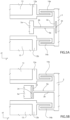
- a particular aspect of the present solution therefore provides, in order to obviate this problem, an asymmetrical arrangement of the elastic suspension elements 6a, 6b, which have an asymmetrical arrangement on opposite sides of the tiltable structure 2 (along the first horizontal axis x).
- the elastic suspension elements 6a, 6b are formed with a different torsional stiffness (having for example a different width) and the piezoresistive sensor 20 is formed in the proximity of the elastic suspension element having a higher torsional stiffness (with respect to the other elastic suspension element).
- the aforementioned first torsional stiffness is smaller than the second torsional stiffness (and the first width w1 is smaller than the second width w2) .
- the second elastic suspension element 6b is therefore formed with the second width w2 (which may for example be equal to 9.4 ⁇ m); while the first elastic suspension element 6a is formed with the first width w1 (which may for example be equal to 8.6 ⁇ m, that is with a reduction of 0.8 ⁇ m with respect to the second width w2).
- the differential reduction in torsional stiffness of one of the elastic suspension elements 6a, 6b with respect to the other is such that the percentage difference between the first torsional stiffness and the second torsional stiffness is comprised between 10% and 50%; moreover, the percentage difference between the first width w1 and the second width w2 may be comprised between 2% and 50%.
- the present Applicant has verified the possibility of decreasing the aforementioned first width w1 even by 50% with respect to the second width w2; a greater decrease, although it might potentially lead to an even greater increase in the opening angle, might in fact entail an excessive reduction in shock resistance, in particular along the orthogonal axis z and along the second horizontal axis y, due to the increased extent of movement (so-called "displacement") of the elastic suspension element having the reduced width.
- the second width w2 differs from the first width w1 preferably by no more than 50%, in order to avoid robustness problems for the microelectromechanical device 1.
- a further embodiment of the present solution provides for a particular shape of one or both of the elastic suspension elements 6a, 6b, which in this case have a substantially a "T" shape.
- one or both of the elastic suspension elements 6a, 6b in this case have: a body portion 30, having a substantially linear extension, in the embodiment illustrated along the first horizontal axis x; and a head portion 32, also having a substantially linear extension, in the embodiment illustrated along the second horizontal axis y, orthogonally with respect to the body portion 30.
- the aforementioned body and head portions 30, 32 substantially have a same width in the direction transverse to the aforementioned linear extension, in the horizontal plane xy, corresponding to the aforementioned first or second width (what has been previously discussed on the asymmetrical arrangement of the elastic suspension elements being in fact valid also in this case).
- the body and head portions 30, 32 both have substantially the same first width w1 (the corresponding first elastic suspension element 6a being associated with the first support element 5a without a piezoresistive sensor).
- the aforementioned head portion 32 is formed in the tiltable structure 2, at the connecting portion with the respective elastic suspension element (in the example with the first elastic suspension element 6a); an opening 34 is therefore formed in this case in the aforementioned connecting portion of the tiltable structure 2, having a main extension along the second horizontal axis y, so that the aforementioned head portion 32 is interposed between the same opening 34, on one side, and the cavity 3, on the other side (along the first horizontal axis x).
- the aforementioned head portion 32 is formed instead in the associated support element (in the example, in the first support element 5a), at the connecting portion with the respective elastic suspension element (in the example with the first elastic suspension element 6a); the opening 34 is therefore formed in this case in the aforementioned connecting portion of the associated support element, having again a main extension along the second horizontal axis y, so that the aforementioned head portion 32 is interposed between the same opening 34, on one side, and the cavity 3, on the other side (again, along the first horizontal axis x) .
- the piezoresistive sensor 20 is not formed at the support element 5a, 5b wherein the aforementioned head portion 32 of the elastic suspension element 6a, 6b is also formed.
- the solution described allows an increase in the opening angle of the microelectromechanical device 1 to be obtained, with minor structural changes with respect to structures of a known type and, in particular, keeping the size of the relative die 1' of semiconductor material unchanged and without requiring changes in the arrangement of the piezoelectric structure 13 of the driving arms 12a-12d.
- the present solution allows to fully exploit the advantages of the piezoelectric actuation (i.e., the use of reduced bias voltages with a reduced energy consumption to obtain high displacements), while having improved mechanical and electrical performance compared to known solutions.
- the microelectromechanical mirror device 1 may therefore be used in a picoprojector (or miniaturized projector) 40, which is operatively coupled to a portable electronic apparatus 41 (for example a smartphone or augmented reality glasses), as schematically illustrated with reference to Figure 6 .
- a picoprojector or miniaturized projector
- portable electronic apparatus 41 for example a smartphone or augmented reality glasses
- the picoprojector 40 of Figure 6 comprises a light source 42, for example of a laser type, for generating a light beam 43; the microelectronic device 1, acting as a mirror and for receiving the light beam 43 and directing it towards a screen or display surface 45 (external and arranged at a distance from the picoprojector 40); a first driving circuit 46, for providing suitable control signals to the light source 42, for the generation of the light beam 43 based on an image to be projected; a second driving circuit 48, for providing driving signals to the actuation structure of the microelectronic mirror device 1; and a communication interface 49, for receiving, from a control unit 50, which is external, for example being included in the portable apparatus 41, information about the image to be generated, for example in the form of a pixel matrix. This information is sent at the input for driving the light source 42.
- a control unit 50 which is external, for example being included in the portable apparatus 41, information about the image to be generated, for example in the form of a pixel matrix. This
- the solution described may also be applied in the case of a biaxial embodiment of the microelectromechanical mirror device 1 (in a manner similar to what has been described in detail in the aforementioned European patent application 3 666 727 A1 ), that is in the case wherein the tiltable structure 2 is capable of performing rotation movements both around the first rotation axis (coinciding with the first median axis of symmetry X parallel to the first horizontal axis x), and around a second rotation axis (coinciding with the second median axis of symmetry Y parallel to the second horizontal axis y).
- variations may generally be provided as regards the shape of the elements constituting the microelectromechanical mirror device 1, for example different shapes of the tiltable structure 2 (and of the corresponding reflecting surface 2'), or different shapes and/or arrangements of the driving arms 12a-12d.
- first and second elastic suspension elements 6a, 6b might be, instead of a linear type, alternatively of a folded type.
Landscapes
- Physics & Mathematics (AREA)
- General Physics & Mathematics (AREA)
- Optics & Photonics (AREA)
- Engineering & Computer Science (AREA)
- Computer Hardware Design (AREA)
- Microelectronics & Electronic Packaging (AREA)
- Micromachines (AREA)
Claims (14)
- Mikroelektromechanische Spiegelvorrichtung (1), die Folgendes umfasst:eine feste Struktur (4), die einen Hohlraum (3) definiert;eine kippbare Struktur (2), die eine reflektierende Oberfläche (2') trägt, elastisch über dem Hohlraum (3) aufgehängt ist und eine Haupterstreckung in einer horizontalen Ebene (xy) aufweist;mindestens ein erstes Paar Antriebsarme (12a, 12b), die elastisch mit der kippbaren Struktur (2) gekoppelt sind und jeweilige Bereiche (13) aus piezoelektrischem Material tragen, die dazu konfiguriert sind, vorgespannt zu werden, um eine Drehung der kippbaren Struktur (2) um mindestens eine erste Drehachse (X), die parallel zu einer ersten horizontalen Achse (x) der horizontalen Ebene (xy) verläuft, zu bewirken;elastische Aufhängungselemente (6a, 6b), die dazu konfiguriert sind, die kippbare Struktur (2) elastisch mit der festen Struktur (4) an der ersten Drehachse (X) zu koppeln, steif gegenüber Bewegungen außerhalb der horizontalen Ebene (xy) und nachgiebig gegenüber Verdrehung um die erste Drehachse (X) sind, wobei sich die elastischen Aufhängungselemente (6a, 6b) zwischen der kippbaren Struktur (2) und der festen Struktur (4) erstrecken; undeinen piezoresistiven Sensor (20), der dazu konfiguriert ist, ein Detektionssignal bereitzustellen, das mit der Drehung der kippbaren Struktur (2) um die erste Drehachse (X) verbunden ist,wobei die elastischen Aufhängungselemente (6a, 6b) ein erstes (6a) und ein zweites (6b) elastisches Aufhängungselement umfassen, die an gegenüberliegenden Seiten entlang der ersten horizontalen Achse (x) mit der kippbaren Struktur (2) gekoppelt sind; wobei das erste elastische Aufhängungselement (6a) mit einer ersten Verdrehsteifigkeit ausgebildet ist und das zweite elastische Aufhängungselement (6b) mit einer zweiten Verdrehsteifigkeit ausgebildet ist,dadurch gekennzeichnet, dass sich die zweite Verdrehsteifigkeit von der ersten Verdrehsteifigkeit unterscheidet;und dass der piezoresistive Sensor (20) in der Nähe des elastischen Aufhängungselements, zwischen dem ersten und dem zweiten elastischen Aufhängungselement (6a, 6b), angeordnet ist, das eine höhere Verdrehsteifigkeit aufweist.
- Vorrichtung nach Anspruch 1, wobei sich das erste und das zweite elastische Aufhängungselement (6a, 6b) entlang der ersten Drehachse (X) erstrecken und entlang einer zweiten Achse (y) der horizontalen Ebene (xy), die orthogonal zur ersten horizontalen Achse (x) verläuft, eine jeweilige erste (w1) und zweite (w2) Breite aufweisen; wobei sich die erste Breite (w1) von der zweiten Breite (w2) unterscheidet.
- Vorrichtung nach Anspruch 2, wobei ein prozentualer Unterschied zwischen der zweiten Breite (w2) und der ersten Breite (w1) zwischen 2 % und 50 % liegt.
- Vorrichtung nach einem der vorhergehenden Ansprüche, wobei ein prozentualer Unterschied zwischen der zweiten Verdrehsteifigkeit und der ersten Verdrehsteifigkeit zwischen 10 % und 50 % liegt.
- Vorrichtung nach einem der vorhergehenden Ansprüche, wobei die feste Struktur (4) in der horizontalen Ebene (xy) einen Rahmen (4') bildet, der den Hohlraum (3) begrenzt und umgibt, und außerdem ein erstes und ein zweites Stützelement (5a, 5b) aufweist, die sich auf gegenüberliegenden Seiten der kippbaren Struktur (2) in Längsrichtung entlang der ersten Drehachse (X) innerhalb des Hohlraums (3) vom Rahmen (4') erstrecken; wobei sich das erste und das zweite elastische Aufhängungselement (6a, 6b) zwischen der kippbaren Struktur (2) und jeweils einem des ersten und des zweiten Stützelements (5a, 5b) erstrecken und wobei der piezoresistive Sensor (20) am zweiten Stützelement (5b) ausgebildet ist.
- Vorrichtung nach Anspruch 4 oder 5, wobei sich das erste und das zweite elastische Aufhängungselement (6a, 6b) entlang der ersten Drehachse (X) erstrecken und entlang einer zweiten Achse (y) der horizontalen Ebene (xy), die orthogonal zur ersten horizontalen Achse (x) verläuft, eine jeweilige erste (w1) und zweite (w2) Breite aufweisen; und wobei die erste Breite (w1) kleiner ist als die zweite Breite (w2).
- Vorrichtung nach einem der vorhergehenden Ansprüche, wobei das erste (6a) und das zweite (6b) elastische Aufhängungselement eine lineare Erstreckung entlang der ersten Drehachse (X) aufweisen.
- Vorrichtung nach einem der Ansprüche 1-6, wobei mindestens eines des ersten (6a) und des zweiten (6b) elastischen Aufhängungselements eine "T"-Form aufweist, die einen Körperabschnitt (30) mit linearer Erstreckung entlang der ersten horizontalen Achse (x) und einen Kopfabschnitt (32) mit linearer Erstreckung entlang einer zweiten horizontalen Achse (y), die in Bezug zu dem Körperabschnitt (30) orthogonal verläuft, aufweist.
- Vorrichtung nach Anspruch 8, wenn sie von den Ansprüchen 2, 3 oder 6 abhängig ist, wobei der Körperabschnitt (30) und der Kopfabschnitt (32) eine gleiche Breite in der Richtung quer zur zuvor genannten linearen Erstreckung entlang der ersten horizontalen Achse (x) bzw. der zweiten horizontalen Achse (y), entsprechend der ersten (w1) oder zweiten (w2) Breite, aufweisen.
- Vorrichtung nach Anspruch 8 oder 9, wobei der Kopfabschnitt (32) in der kippbaren Struktur (2) an einem Verbindungsabschnitt mit dem jeweiligen elastischen Aufhängungselement (6a, 6b) ausgebildet ist, wobei in dem Verbindungsabschnitt der kippbaren Struktur (2) eine Öffnung (34) ausgebildet ist, die eine Haupterstreckung entlang der zweiten horizontalen Achse (y) aufweist, so dass der Kopfabschnitt (32) zwischen der Öffnung (34) auf einer Seite und dem jeweiligen elastischen Aufhängungselement (6a, 6b) auf der anderen Seite eingefügt ist.
- Vorrichtung nach Anspruch 8 oder 9, wobei die feste Struktur (4) in der horizontalen Ebene (xy) einen Rahmen (4') bildet, der den Hohlraum (3) begrenzt und umgibt, und außerdem ein erstes und ein zweites Stützelement (5a, 5b) aufweist, die sich auf gegenüberliegenden Seiten der kippbaren Struktur (2) in Längsrichtung entlang der ersten Drehachse (X) innerhalb des Hohlraums (3) vom Rahmen (4') erstrecken; wobei sich das erste und das zweite elastische Aufhängungselement (6a, 6b) zwischen der kippbaren Struktur (2) und einem jeweiligen des ersten und des zweiten Stützelements (5a, 5b) erstrecken; und wobei der Kopfabschnitt (32) in dem zugehörigen Stützelement (5a, 5b) an einem Verbindungsabschnitt mit dem jeweiligen elastischen Aufhängungselement (6a, 6b) ausgebildet ist, wobei in dem Verbindungsabschnitt des zugehörigen Stützelements (5a, 5b) eine Öffnung (34) ausgebildet ist, die eine Haupterstreckung entlang der zweiten horizontalen Achse (y) aufweist, so dass der Kopfabschnitt (32) zwischen der Öffnung (34) auf einer Seite und dem jeweiligen elastischen Aufhängungselement (6a, 6b) auf der anderen Seite eingefügt ist.
- Vorrichtung nach einem der vorhergehenden Ansprüche, die ferner elastische Entkopplungselemente (14a, 14b) umfasst, die die kippbare Struktur (2) mit den Antriebsarmen (12a, 12b) des ersten Paares auf gegenüberliegenden Seiten und in der Nähe der ersten Drehachse (X) koppeln und steif für Bewegungen außerhalb der horizontalen Ebene (xy) und nachgiebig bei Verdrehung um eine Achse parallel zur ersten Drehachse (X) sind.
- Vorrichtung nach einem der vorhergehenden Ansprüche, die ferner ein zweites Paar Antriebsarme (12c, 12d) umfasst, die in Bezug auf eine zweite horizontale Achse (y) der horizontalen Ebene (xy), die orthogonal zur ersten horizontalen Achse (x) verläuft, symmetrisch zum ersten Paar Antriebsarme (12a, 12b) angeordnet ist; wobei die Antriebsarme (12c, 12d) des zweiten Paares jeweilige Bereiche (13) aus piezoelektrischem Material tragen und über jeweilige elastische Entkopplungselemente (14c, 14d) auf gegenüberliegenden Seiten und in der Nähe der ersten Drehachse (X) elastisch mit der kippbaren Struktur gekoppelt, steif für Bewegungen außerhalb der horizontalen Ebene (xy) und nachgiebig bei Verdrehung um die erste Drehachse (X) sind.
- Miniaturisiertes Projektionsgerät (40) zur Verwendung in einem tragbaren elektronischen Gerät (41), das die mikroelektromechanische Spiegelvorrichtung (1) nach einem der vorhergehenden Ansprüche umfasst; ferner Folgendes umfassend:eine Lichtquelle (42), die betreibbar ist, um einen Lichtstrahl (43) basierend auf einem zu erzeugenden Bild zu erzeugen;eine Antriebsschaltung (48), die dazu konfiguriert ist, elektrische Antriebssignale bereitzustellen, um die Drehung der kippbaren Struktur (2) zu bewirken.
Applications Claiming Priority (1)
| Application Number | Priority Date | Filing Date | Title |
|---|---|---|---|
| IT202100010616 | 2021-04-27 |
Publications (2)
| Publication Number | Publication Date |
|---|---|
| EP4082962A1 EP4082962A1 (de) | 2022-11-02 |
| EP4082962B1 true EP4082962B1 (de) | 2025-03-05 |
Family
ID=76808075
Family Applications (1)
| Application Number | Title | Priority Date | Filing Date |
|---|---|---|---|
| EP22169585.1A Active EP4082962B1 (de) | 2021-04-27 | 2022-04-22 | Mikroelektromechanische spiegelvorrichtung mit piezoelektrischer ansteuerung und verbessertem öffnungswinkel |
Country Status (3)
| Country | Link |
|---|---|
| US (1) | US12270990B2 (de) |
| EP (1) | EP4082962B1 (de) |
| CN (2) | CN218099782U (de) |
Family Cites Families (5)
| Publication number | Priority date | Publication date | Assignee | Title |
|---|---|---|---|---|
| JP2008116668A (ja) * | 2006-11-02 | 2008-05-22 | Seiko Epson Corp | アクチュエータ、光スキャナおよび画像形成装置 |
| JPWO2011152215A1 (ja) | 2010-06-02 | 2013-07-25 | 日本電気株式会社 | 光走査素子およびそれを用いた画像表示装置 |
| DE102017206252A1 (de) | 2017-04-11 | 2018-10-11 | Fraunhofer-Gesellschaft zur Förderung der angewandten Forschung e.V. | Mikromechanische Spiegelvorrichtung |
| EP3666727B1 (de) | 2018-12-14 | 2024-10-02 | STMicroelectronics S.r.l. | Mikroelektromechanische vorrichtung mit einer durch piezoelektrische ansteuerung kippbaren struktur mit verbesserten mechanischen und elektrischen eigenschaften |
| US11714276B2 (en) * | 2020-05-12 | 2023-08-01 | Microsoft Technology Licensing, Llc | Microelectromechanical system (MEMS) scanner having a torsional beam flexure with variable width |
-
2022
- 2022-04-22 EP EP22169585.1A patent/EP4082962B1/de active Active
- 2022-04-22 US US17/727,117 patent/US12270990B2/en active Active
- 2022-04-26 CN CN202220989120.9U patent/CN218099782U/zh active Active
- 2022-04-26 CN CN202210451681.8A patent/CN115248499A/zh active Pending
Also Published As
| Publication number | Publication date |
|---|---|
| CN115248499A (zh) | 2022-10-28 |
| CN218099782U (zh) | 2022-12-20 |
| EP4082962A1 (de) | 2022-11-02 |
| US20220342203A1 (en) | 2022-10-27 |
| US12270990B2 (en) | 2025-04-08 |
Similar Documents
| Publication | Publication Date | Title |
|---|---|---|
| US11953813B2 (en) | Microelectromechanical device with a structure tiltable by piezoelectric actuation having improved mechanical and electrical characteristics | |
| US11933966B2 (en) | Resonant MEMS device having a tiltable, piezoelectrically controlled micromirror | |
| CN111717884B (zh) | 具有改善特性的压电致动双轴线谐振微机电反射镜结构 | |
| US11353694B2 (en) | Microelectromechanical mirror device with piezoelectric actuation, having an improved structure | |
| EP3447560B1 (de) | Mems-reflektorsystem | |
| US11300778B2 (en) | MEMS device with suspension structure and method of making a MEMS device | |
| US12043540B2 (en) | Micro-electro-mechanical device with a shock-protected tiltable structure | |
| EP4242724A1 (de) | Biaxiale mikroelektromechanische spiegelvorrichtung mit piezoelektrischer betätigung | |
| CN114314497B (zh) | 具有通过绕两个旋转轴的压电致动倾斜的结构的微机电设备 | |
| CN220467578U (zh) | 包括微机电镜设备的设备及微机电镜设备 | |
| EP4082962B1 (de) | Mikroelektromechanische spiegelvorrichtung mit piezoelektrischer ansteuerung und verbessertem öffnungswinkel | |
| EP4261592B1 (de) | Mikroelektromechanische spiegelvorrichtung mit piezoelektrischer betätigung mit verbesserter spannungsfestigkeit | |
| US12585107B2 (en) | Microelectromechanical mirror device with piezoelectric actuation and optimized size | |
| US20250388455A1 (en) | Mems device having a tiltable structure and quasi-static piezoelectric actuation, in particular micromirror, with improved efficiency | |
| US12434961B2 (en) | Scanning MEMS mirror device |
Legal Events
| Date | Code | Title | Description |
|---|---|---|---|
| PUAI | Public reference made under article 153(3) epc to a published international application that has entered the european phase |
Free format text: ORIGINAL CODE: 0009012 |
|
| STAA | Information on the status of an ep patent application or granted ep patent |
Free format text: STATUS: THE APPLICATION HAS BEEN PUBLISHED |
|
| AK | Designated contracting states |
Kind code of ref document: A1 Designated state(s): AL AT BE BG CH CY CZ DE DK EE ES FI FR GB GR HR HU IE IS IT LI LT LU LV MC MK MT NL NO PL PT RO RS SE SI SK SM TR |
|
| STAA | Information on the status of an ep patent application or granted ep patent |
Free format text: STATUS: REQUEST FOR EXAMINATION WAS MADE |
|
| 17P | Request for examination filed |
Effective date: 20230502 |
|
| RBV | Designated contracting states (corrected) |
Designated state(s): AL AT BE BG CH CY CZ DE DK EE ES FI FR GB GR HR HU IE IS IT LI LT LU LV MC MK MT NL NO PL PT RO RS SE SI SK SM TR |
|
| GRAP | Despatch of communication of intention to grant a patent |
Free format text: ORIGINAL CODE: EPIDOSNIGR1 |
|
| STAA | Information on the status of an ep patent application or granted ep patent |
Free format text: STATUS: GRANT OF PATENT IS INTENDED |
|
| RIC1 | Information provided on ipc code assigned before grant |
Ipc: G02B 26/10 20060101ALI20240924BHEP Ipc: G02B 26/08 20060101ALI20240924BHEP Ipc: B81B 3/00 20060101AFI20240924BHEP |
|
| INTG | Intention to grant announced |
Effective date: 20241014 |
|
| GRAS | Grant fee paid |
Free format text: ORIGINAL CODE: EPIDOSNIGR3 |
|
| GRAA | (expected) grant |
Free format text: ORIGINAL CODE: 0009210 |
|
| STAA | Information on the status of an ep patent application or granted ep patent |
Free format text: STATUS: THE PATENT HAS BEEN GRANTED |
|
| AK | Designated contracting states |
Kind code of ref document: B1 Designated state(s): AL AT BE BG CH CY CZ DE DK EE ES FI FR GB GR HR HU IE IS IT LI LT LU LV MC MK MT NL NO PL PT RO RS SE SI SK SM TR |
|
| REG | Reference to a national code |
Ref country code: GB Ref legal event code: FG4D |
|
| REG | Reference to a national code |
Ref country code: CH Ref legal event code: EP |
|
| REG | Reference to a national code |
Ref country code: IE Ref legal event code: FG4D |
|
| REG | Reference to a national code |
Ref country code: DE Ref legal event code: R096 Ref document number: 602022011305 Country of ref document: DE |
|
| PG25 | Lapsed in a contracting state [announced via postgrant information from national office to epo] |
Ref country code: RS Free format text: LAPSE BECAUSE OF FAILURE TO SUBMIT A TRANSLATION OF THE DESCRIPTION OR TO PAY THE FEE WITHIN THE PRESCRIBED TIME-LIMIT Effective date: 20250605 |
|
| PG25 | Lapsed in a contracting state [announced via postgrant information from national office to epo] |
Ref country code: FI Free format text: LAPSE BECAUSE OF FAILURE TO SUBMIT A TRANSLATION OF THE DESCRIPTION OR TO PAY THE FEE WITHIN THE PRESCRIBED TIME-LIMIT Effective date: 20250305 |
|
| PGFP | Annual fee paid to national office [announced via postgrant information from national office to epo] |
Ref country code: DE Payment date: 20250319 Year of fee payment: 4 |
|
| REG | Reference to a national code |
Ref country code: NL Ref legal event code: MP Effective date: 20250305 |
|
| PG25 | Lapsed in a contracting state [announced via postgrant information from national office to epo] |
Ref country code: ES Free format text: LAPSE BECAUSE OF FAILURE TO SUBMIT A TRANSLATION OF THE DESCRIPTION OR TO PAY THE FEE WITHIN THE PRESCRIBED TIME-LIMIT Effective date: 20250305 |
|
| REG | Reference to a national code |
Ref country code: LT Ref legal event code: MG9D |
|
| PG25 | Lapsed in a contracting state [announced via postgrant information from national office to epo] |
Ref country code: NO Free format text: LAPSE BECAUSE OF FAILURE TO SUBMIT A TRANSLATION OF THE DESCRIPTION OR TO PAY THE FEE WITHIN THE PRESCRIBED TIME-LIMIT Effective date: 20250605 |
|
| PG25 | Lapsed in a contracting state [announced via postgrant information from national office to epo] |
Ref country code: HR Free format text: LAPSE BECAUSE OF FAILURE TO SUBMIT A TRANSLATION OF THE DESCRIPTION OR TO PAY THE FEE WITHIN THE PRESCRIBED TIME-LIMIT Effective date: 20250305 |
|
| PG25 | Lapsed in a contracting state [announced via postgrant information from national office to epo] |
Ref country code: LV Free format text: LAPSE BECAUSE OF FAILURE TO SUBMIT A TRANSLATION OF THE DESCRIPTION OR TO PAY THE FEE WITHIN THE PRESCRIBED TIME-LIMIT Effective date: 20250305 |
|
| PG25 | Lapsed in a contracting state [announced via postgrant information from national office to epo] |
Ref country code: GR Free format text: LAPSE BECAUSE OF FAILURE TO SUBMIT A TRANSLATION OF THE DESCRIPTION OR TO PAY THE FEE WITHIN THE PRESCRIBED TIME-LIMIT Effective date: 20250606 Ref country code: BG Free format text: LAPSE BECAUSE OF FAILURE TO SUBMIT A TRANSLATION OF THE DESCRIPTION OR TO PAY THE FEE WITHIN THE PRESCRIBED TIME-LIMIT Effective date: 20250305 |
|
| REG | Reference to a national code |
Ref country code: AT Ref legal event code: MK05 Ref document number: 1772834 Country of ref document: AT Kind code of ref document: T Effective date: 20250305 |
|
| PG25 | Lapsed in a contracting state [announced via postgrant information from national office to epo] |
Ref country code: NL Free format text: LAPSE BECAUSE OF FAILURE TO SUBMIT A TRANSLATION OF THE DESCRIPTION OR TO PAY THE FEE WITHIN THE PRESCRIBED TIME-LIMIT Effective date: 20250305 |
|
| PG25 | Lapsed in a contracting state [announced via postgrant information from national office to epo] |
Ref country code: SE Free format text: LAPSE BECAUSE OF FAILURE TO SUBMIT A TRANSLATION OF THE DESCRIPTION OR TO PAY THE FEE WITHIN THE PRESCRIBED TIME-LIMIT Effective date: 20250305 |
|
| PG25 | Lapsed in a contracting state [announced via postgrant information from national office to epo] |
Ref country code: SM Free format text: LAPSE BECAUSE OF FAILURE TO SUBMIT A TRANSLATION OF THE DESCRIPTION OR TO PAY THE FEE WITHIN THE PRESCRIBED TIME-LIMIT Effective date: 20250305 |
|
| PG25 | Lapsed in a contracting state [announced via postgrant information from national office to epo] |
Ref country code: PT Free format text: LAPSE BECAUSE OF FAILURE TO SUBMIT A TRANSLATION OF THE DESCRIPTION OR TO PAY THE FEE WITHIN THE PRESCRIBED TIME-LIMIT Effective date: 20250707 |
|
| PG25 | Lapsed in a contracting state [announced via postgrant information from national office to epo] |
Ref country code: IT Free format text: LAPSE BECAUSE OF FAILURE TO SUBMIT A TRANSLATION OF THE DESCRIPTION OR TO PAY THE FEE WITHIN THE PRESCRIBED TIME-LIMIT Effective date: 20250305 Ref country code: PL Free format text: LAPSE BECAUSE OF FAILURE TO SUBMIT A TRANSLATION OF THE DESCRIPTION OR TO PAY THE FEE WITHIN THE PRESCRIBED TIME-LIMIT Effective date: 20250305 |
|
| PG25 | Lapsed in a contracting state [announced via postgrant information from national office to epo] |
Ref country code: AT Free format text: LAPSE BECAUSE OF FAILURE TO SUBMIT A TRANSLATION OF THE DESCRIPTION OR TO PAY THE FEE WITHIN THE PRESCRIBED TIME-LIMIT Effective date: 20250305 |
|
| PG25 | Lapsed in a contracting state [announced via postgrant information from national office to epo] |
Ref country code: EE Free format text: LAPSE BECAUSE OF FAILURE TO SUBMIT A TRANSLATION OF THE DESCRIPTION OR TO PAY THE FEE WITHIN THE PRESCRIBED TIME-LIMIT Effective date: 20250305 Ref country code: CZ Free format text: LAPSE BECAUSE OF FAILURE TO SUBMIT A TRANSLATION OF THE DESCRIPTION OR TO PAY THE FEE WITHIN THE PRESCRIBED TIME-LIMIT Effective date: 20250305 |
|
| PG25 | Lapsed in a contracting state [announced via postgrant information from national office to epo] |
Ref country code: RO Free format text: LAPSE BECAUSE OF FAILURE TO SUBMIT A TRANSLATION OF THE DESCRIPTION OR TO PAY THE FEE WITHIN THE PRESCRIBED TIME-LIMIT Effective date: 20250305 |
|
| PG25 | Lapsed in a contracting state [announced via postgrant information from national office to epo] |
Ref country code: SK Free format text: LAPSE BECAUSE OF FAILURE TO SUBMIT A TRANSLATION OF THE DESCRIPTION OR TO PAY THE FEE WITHIN THE PRESCRIBED TIME-LIMIT Effective date: 20250305 |
|
| PG25 | Lapsed in a contracting state [announced via postgrant information from national office to epo] |
Ref country code: IS Free format text: LAPSE BECAUSE OF FAILURE TO SUBMIT A TRANSLATION OF THE DESCRIPTION OR TO PAY THE FEE WITHIN THE PRESCRIBED TIME-LIMIT Effective date: 20250705 |
|
| REG | Reference to a national code |
Ref country code: CH Ref legal event code: H13 Free format text: ST27 STATUS EVENT CODE: U-0-0-H10-H13 (AS PROVIDED BY THE NATIONAL OFFICE) Effective date: 20251125 |
|
| REG | Reference to a national code |
Ref country code: DE Ref legal event code: R097 Ref document number: 602022011305 Country of ref document: DE |
|
| PG25 | Lapsed in a contracting state [announced via postgrant information from national office to epo] |
Ref country code: LU Free format text: LAPSE BECAUSE OF NON-PAYMENT OF DUE FEES Effective date: 20250422 |
|
| PG25 | Lapsed in a contracting state [announced via postgrant information from national office to epo] |
Ref country code: MC Free format text: LAPSE BECAUSE OF FAILURE TO SUBMIT A TRANSLATION OF THE DESCRIPTION OR TO PAY THE FEE WITHIN THE PRESCRIBED TIME-LIMIT Effective date: 20250305 |
|
| REG | Reference to a national code |
Ref country code: BE Ref legal event code: MM Effective date: 20250430 |
|
| PLBE | No opposition filed within time limit |
Free format text: ORIGINAL CODE: 0009261 |
|
| STAA | Information on the status of an ep patent application or granted ep patent |
Free format text: STATUS: NO OPPOSITION FILED WITHIN TIME LIMIT |
|
| PG25 | Lapsed in a contracting state [announced via postgrant information from national office to epo] |
Ref country code: DK Free format text: LAPSE BECAUSE OF FAILURE TO SUBMIT A TRANSLATION OF THE DESCRIPTION OR TO PAY THE FEE WITHIN THE PRESCRIBED TIME-LIMIT Effective date: 20250305 |
|
| REG | Reference to a national code |
Ref country code: CH Ref legal event code: L10 Free format text: ST27 STATUS EVENT CODE: U-0-0-L10-L00 (AS PROVIDED BY THE NATIONAL OFFICE) Effective date: 20260114 |
|
| PG25 | Lapsed in a contracting state [announced via postgrant information from national office to epo] |
Ref country code: BE Free format text: LAPSE BECAUSE OF NON-PAYMENT OF DUE FEES Effective date: 20250430 |
|
| PG25 | Lapsed in a contracting state [announced via postgrant information from national office to epo] |
Ref country code: CH Free format text: LAPSE BECAUSE OF NON-PAYMENT OF DUE FEES Effective date: 20250430 |
|
| 26N | No opposition filed |
Effective date: 20251208 |
|
| PG25 | Lapsed in a contracting state [announced via postgrant information from national office to epo] |
Ref country code: IE Free format text: LAPSE BECAUSE OF NON-PAYMENT OF DUE FEES Effective date: 20250422 |
|
| PG25 | Lapsed in a contracting state [announced via postgrant information from national office to epo] |
Ref country code: FR Free format text: LAPSE BECAUSE OF NON-PAYMENT OF DUE FEES Effective date: 20250505 |