EP4083369A1 - Raccord fileté pour tubes - Google Patents
Raccord fileté pour tubes Download PDFInfo
- Publication number
- EP4083369A1 EP4083369A1 EP20905534.2A EP20905534A EP4083369A1 EP 4083369 A1 EP4083369 A1 EP 4083369A1 EP 20905534 A EP20905534 A EP 20905534A EP 4083369 A1 EP4083369 A1 EP 4083369A1
- Authority
- EP
- European Patent Office
- Prior art keywords
- thread
- box
- arc
- curvature radius
- threaded joint
- Prior art date
- Legal status (The legal status is an assumption and is not a legal conclusion. Google has not performed a legal analysis and makes no representation as to the accuracy of the status listed.)
- Granted
Links
Images





Classifications
-
- F—MECHANICAL ENGINEERING; LIGHTING; HEATING; WEAPONS; BLASTING
- F16—ENGINEERING ELEMENTS AND UNITS; GENERAL MEASURES FOR PRODUCING AND MAINTAINING EFFECTIVE FUNCTIONING OF MACHINES OR INSTALLATIONS; THERMAL INSULATION IN GENERAL
- F16L—PIPES; JOINTS OR FITTINGS FOR PIPES; SUPPORTS FOR PIPES, CABLES OR PROTECTIVE TUBING; MEANS FOR THERMAL INSULATION IN GENERAL
- F16L15/00—Screw-threaded joints; Forms of screw-threads for such joints
- F16L15/001—Screw-threaded joints; Forms of screw-threads for such joints with conical threads
-
- E—FIXED CONSTRUCTIONS
- E21—EARTH OR ROCK DRILLING; MINING
- E21B—EARTH OR ROCK DRILLING; OBTAINING OIL, GAS, WATER, SOLUBLE OR MELTABLE MATERIALS OR A SLURRY OF MINERALS FROM WELLS
- E21B17/00—Drilling rods or pipes; Flexible drill strings; Kellies; Drill collars; Sucker rods; Cables; Casings; Tubings
- E21B17/02—Couplings; joints
- E21B17/04—Couplings; joints between rod or the like and bit or between rod and rod or the like
- E21B17/042—Threaded
-
- F—MECHANICAL ENGINEERING; LIGHTING; HEATING; WEAPONS; BLASTING
- F16—ENGINEERING ELEMENTS AND UNITS; GENERAL MEASURES FOR PRODUCING AND MAINTAINING EFFECTIVE FUNCTIONING OF MACHINES OR INSTALLATIONS; THERMAL INSULATION IN GENERAL
- F16L—PIPES; JOINTS OR FITTINGS FOR PIPES; SUPPORTS FOR PIPES, CABLES OR PROTECTIVE TUBING; MEANS FOR THERMAL INSULATION IN GENERAL
- F16L15/00—Screw-threaded joints; Forms of screw-threads for such joints
- F16L15/06—Screw-threaded joints; Forms of screw-threads for such joints characterised by the shape of the screw-thread
Definitions
- This disclosure relates to a threaded joint for pipes.
- Threaded joints for pipes are widely used to connect steel pipes which are used in oil industrial facilities such as oil country tubular goods (OCTG).
- OCTG oil country tubular goods
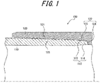
- FIG. 1 schematically illustrates an example of the structure of a typical threaded joint for pipes.
- the threaded joint for pipes 100 includes a pin 110 provided with a male thread portion 111, which is a male tapered thread, at one end of a first pipe, and a box 120 provided with a female thread portion 121, which is a female tapered thread to be screwed with the male thread portion, at one end of a second pipe.
- An unthreaded portion 112 which is a portion without thread, is provided at the tip of the pin 110, that is, on the tip side farther than the male thread portion 111.
- the unthreaded portion 112 includes a seal portion 113 and a shoulder portion 114 almost perpendicular to the pipe axis.
- the box 120 is provided with an unthreaded portion 122 on a position nearer the center side in the pipe axis direction than the female thread portion 121, that is, on the side opposite to the end.
- the unthreaded 122 also includes a seal portion 123 and a shoulder portion 124 almost perpendicular to the pipe axis.
- FIG. 2 schematically illustrates the shape of a thread groove 200 of the female thread portion 121 formed in the box 120 in the typical threaded joint for pipes.
- the upper side is the thread bottom side
- the thread groove 200 has a substantially trapezoidal shape with a straight thread bottom portion 210 parallel to the taper of the female thread.
- the thread groove 200 includes a linear load flank 220 on the left side of FIG. 2 , that is, on the rear side in the insertion direction of the pin 100.
- the thread groove 200 also includes a linear stabbing flank 230 on the right side of FIG. 2 , that is, on the front side in the insertion direction of the pin 100.
- the thread groove 200 includes a corner portion 240 on the load flank side and a corner portion 250 on the stabbing flank side on the thread bottom side, and the corner portion 240 on the load flank side and the corner portion 250 on the stabbing flank side are each composed of one arc.
- Such a threaded joint for pipes is required to have various properties such as tensile resistance, compression resistance, bending resistance, and sealing properties.
- the excavation and production environments are becoming more and more severe, especially in recent years, because wells for drilling crude oil and natural gas are deepened, and the number of horizontal wells and inclined wells is increasing in addition to conventional vertical wells. Therefore, the threaded joint for pipes is required not to fracture even in such harsh environments.
- the fracture of a threaded joint starts from a crack in a thread groove of the box. Especially when a tensile load is applied to the threaded joint, stress is concentrated in the corner portion on the load flank side of a first thread groove, which is a thread groove farthest from the end of the box, so that it is necessary to suppress the occurrence of crack in the first thread groove to prevent the fracture of the threaded joint.
- WO/2015/111117 proposes that the tensile efficiency (TE), the height t of the female thread of the box, and the curvature radius ⁇ of the arc forming the corner portion on the load flank side of the first thread groove be controlled to satisfy the relationship specified by a specific mathematical formula, to prevent the fracture of a threaded joint for pipes.
- the tensile efficiency TE which is one of the parameters used in PTL 1, is a value defined as a ratio of the cross section at a first thread position of the box with respect to the cross section at a raw pipe portion of the pin. As the tensile efficiency increases, it means that the limit tensile properties of the joint increase. Therefore, increasing the outer diameter of the box and increasing the tensile efficiency can improve the limit tensile properties of the joint.
- the raw pipe portion refers to a portion without thread in a pipe.
- PTL 1 controls the tensile efficiency TE, the height t of the female thread of the box, and the curvature radius ⁇ of the arc forming the corner portion on the load flank side of the first thread groove to satisfy the relationship in the following formula.
- TE % 2.25 ⁇ t / ⁇ + 99.9
- the conventional technology cannot solve the two conflicting problems of fracture prevention and cost reduction.
- FEA finite element analysis
- FIG. 3 is a contour diagram illustrating the distribution of plastic strain in the vicinity of the first thread groove in a conventional thread groove shape, as determined by FEA.
- the member located on the upper side of the figure is a box
- the member located on the lower side is a pin
- the thread groove on the right side of the two thread grooves illustrated in the figure is the first thread groove.
- Each thread groove provided in the box is a trapezoidal thread with a straight thread bottom portion parallel to the taper of the female thread.
- the side surfaces of the thread groove include a stabbing flank surface (right side in the figure) and a load flank surface (left side in the figure), and when a tensile load is applied in the pipe axial direction, the load is applied on the load flank surface.
- the thread groove has a corner portion on the load flank side and a corner portion on the stabbing flank side on the thread bottom side, and the corner portion on the load flank side and the corner portion on the stabbing flank side are each composed of one arc.
- plastic strain is concentrated at the corner portions of the first thread groove in a conventional thread groove shape, with the greatest plastic strain at the corner portion on the load flank side.
- FIG. 4 is a contour diagram illustrating the distribution of plastic strain when another arc is further provided at the corner portion on the load flank side of the thread groove illustrated in FIG. 3 .
- the curvature radius of the added second arc is set to 11.5 times the curvature radius of the first arc.
- the thread groove shape illustrated in FIG. 4 corresponds to the thread groove shape in the first embodiment of the present disclosure, which will be described later.
- FIGS. 3 and 4 illustrate the distribution of plastic strain rather than the distribution of stress. This is because, in a portion where stress above a certain level is applied, the stress is relieved by plastic deformation, resulting in an apparently reduced stress. To assess the risk of occurrence of crack in practice, it is more appropriate to use plastic strain than using stress itself.
- a threaded joint with the above-described structure is first subjected to analysis simulating screw tightening, and then the FEA was further carried out under conditions of applying a combined load of tension/compression and internal pressure/external pressure in accordance with ISO 13679: 2002 Test Series A.
- the present disclosure is based on the above finding and has the following primary features.
- the threaded joint for pipes of the present disclosure can be suitably used to connect oil well pipes used for oil and gas exploration and production, line pipes used for transporting oil and gas, and the like.
- the terms “load flank” and “stabbing flank” are used in the usual sense of the technical field.
- the "load flank” refers to a straight flank on the side on which a load is applied by the tensile force in the pipe axial direction
- the “stabbing flank” refers to a straight flank on the opposite side of the load flank.
- the shape of a thread groove refers to the shape of a thread groove when it is formed, that is, before the pin and the box are tightened.
- a threaded joint for pipes in one embodiment of the present disclosure (hereinafter, may be simply referred to as “threaded joint”) includes a pin provided with a male thread portion, which is a male tapered thread, at one end of a first pipe, and a box provided with a female thread portion, which is a female tapered thread to be screwed with the male thread portion, at one end of a second pipe.
- the female thread portion of the box has a plurality of thread grooves, and the thread groove farthest from the end of the box among the plurality of thread grooves is defined as a "first thread groove".
- first thread groove only a thread groove that substantially engages with a thread on the pin side is considered as a thread groove when determining the first thread groove.
- Each of the plurality of thread grooves has a corner portion on a load flank side and a corner portion on a stabbing flank side on the thread bottom side.
- the corner portion on the load flank side of the first thread groove includes at least two arc portions.
- a first arc portion that is directly connected to the load flank and has a first curvature radius
- the other is a second arc portion that is directly or indirectly connected to the first arc portion and has a second curvature radius.
- a ratio of curvature radius which is a ratio of the second curvature radius to the first curvature radius, be 3 or more.
- a second arc portion that satisfies the above conditions, stress concentration in the corner portion on the load flank side can be alleviated, and stress can be distributed over the entire thread bottom. As a result, fracture of the box can be prevented.
- a conventional thread joint has only one arc in the corner portion on the load flank side, so that it is necessary to increase the outer diameter of the box to prevent fracture, as described above.
- the structure of thread grooves other than the first thread groove is not particularly limited in the present disclosure. However, it is preferable that all thread grooves in the box meet the above requirements from the viewpoint of ease of production.
- the corner portion on the load flank side of all thread grooves of the box include a first arc portion that is directly connected to the load flank and has a first curvature radius and a second arc portion that is directly or indirectly connected to the first arc portion and has a second curvature radius, and that a ratio of curvature radius, which is a ratio of the second curvature radius to the first curvature radius, be 3 or more.
- the upper limit of the ratio of curvature radius is not limited. However, when the ratio of curvature radius exceeds 15, the effect of alleviating stress saturates. Therefore, the ratio of curvature radius may be 15 or less. Further, it is preferable that the first arc portion and the second arc portion be smoothly connected so that the connecting portion has a common tangent line. It is more preferable that each arc portion and straight portion of the corner portion on the load flank side be smoothly connected to an adjacent arc portion or straight portion so that the connecting portion has a common tangent line.
- the curvature radius of each of the first and second arc portions is not particularly limited and may be any value.
- the curvature radius of the first arc portion may be, for example, 0.008 to 0.025 inches.
- the curvature radius of the second arc portion may be, for example, 0.030 to 0.200 inches.
- the angle ⁇ of the first arc portion is not particularly limited. However, when the angle ⁇ of the first arc portion is 50 ° or more, the second arc portion does not need to be excessively large, so that the need to increase the size of the thread groove can be further reduced. Therefore, the angle ⁇ of the first arc portion is preferably 50 ° or more. On the other hand, when the angle ⁇ of the first arc portion is 75 ° or less, it is possible to prevent the first arc portion from extending to a position where stress is likely to concentrate, so that the effect of dispersing stress can be further enhanced. Therefore, the angle ⁇ of the first arc portion is preferably 75 ° or less.
- the "angle ⁇ of the first arc portion” is defined as an angle between a straight line “a” parallel to the pipe axis and the radius "r” at the end of the first arc portion on the opposite side of the load flank (see FIGS. 7 to 10 ).
- flank angles of the plurality of thread grooves are not particularly limited and may be any angle.
- the angle of the stabbing flank is preferably +5 to +40 degrees with respective to a straight line perpendicular to the pipe axis.
- the angle of the load flank is preferably -10 to 0 degrees with respective to a straight line perpendicular to the pipe axis.
- the flank angle is defined as positive when the flank surface is inclined toward the thread and negative when it is inclined toward the opposite side of the thread, with respect to a straight line perpendicular to the pipe axis.
- the depth of the thread groove is not particularly limited, but it is preferably between 0.03 and 0.10 inches.
- the number of threads per inch is preferably 4 to 10. Therefore, the thread pitch, which is the distance between threads, is preferably 0.1 to 0.25 inches.
- the thread width which is the width of the thread at the middle height of the thread, is preferably 0.4 to 0.6 times the thread pitch.
- the pin preferably includes a portion without thread (hereafter, referred to as "unthreaded portion”) at the most tip, that is, on the tip side farther than the male thread portion.
- the box preferably includes an unthreaded portion on a position nearer the center side in the pipe axis direction than the female thread portion, that is, on the side opposite to the end.
- the threaded joint of the present disclosure may have any structure if the above conditions are satisfied.
- the threaded joint of the present disclosure may be either a coupling-type threaded joint or an integral-type threaded joint.
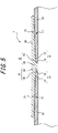
- FIG. 5 schematically illustrates the structure of a coupling-type threaded joint for pipes 1 of one embodiment of the present disclosure.
- a coupling-type threaded joint for pipes is a threaded joint that connects two pipes using a coupling as a box, which is also called thread-and-coupling (T&C) type.
- T&C thread-and-coupling
- the coupling-type threaded joint for pipes 1 includes a pin 10 and a box (coupling) 20.
- the pin 10 has a structure where a male thread portion 11, which is a male tapered thread, is provided at the end of a pipe
- the box 20 has a structure where a female thread portion 21, which is a female tapered thread to be screwed with the male thread portion11 of the pin 10, is provided at both ends of a pipe.
- the pin 10 preferably includes an unthreaded portion 12 at the most tip, that is, on the tip side farther than the male thread portion 11, as illustrated in FIG. 5 .
- the box 20 preferably includes an unthreaded portion 22 on a position nearer the center side in the pipe axis direction than the female thread portion 21, that is, on the side opposite to the end.
- the unthreaded portion preferably includes a seal portion and a shoulder portion as illustrated in FIG. 5 .
- the unthreaded portion 12 of the pin 10 may include a seal portion 13 and a shoulder portion 14 located on the tip side farther than the seal portion 13.
- the unthreaded portion 22 of the box 20 may include a seal portion 23 and a shoulder portion 24 located nearer the center side than the seal portion 23.
- the shoulder portion 14 of the pin 10 may be perpendicular to the pipe axis, or it may be inclined toward the pin side with respect to a straight line perpendicular to the pipe axis.
- the angle between the shoulder portion 14 of the pin 10 and a straight line perpendicular to the pipe axis is preferably 0 to 30 degrees.
- the shape of the seal portion of the pin and the shape of the seal portion of the box are not particularly limited, but they may be, for example, a combination of the following.
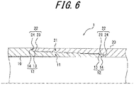
- FIG. 6 schematically illustrates the structure of an integral-type threaded joint for pipes 1 in another embodiment of the present disclosure.
- the pin 10 has a structure where a male thread portion 11, which is a male tapered thread, is provided at one end of a first pipe
- the box 20 has a structure where a female thread portion 21, which is a female tapered thread to be screwed with the male thread portion 11 of the pin 10, is provided at one end of a second pipe.
- the pin 10 preferably includes an unthreaded portion 12 at the most tip, that is, on the tip side farther than the male thread portion 11, as illustrated in FIG. 6 . Further, the pin 10 preferably includes an unthreaded portion 12 on a position nearer the center side in the pipe axis direction than the male thread portion 11, that is, on the side opposite to the end.
- the box 20 also preferably includes an unthreaded portion 22 on a position nearer the center side in the pipe axis direction than the female thread portion 21, that is, on the side opposite to the end. Further, the box 20 preferably includes an unthreaded portion 22 at the most tip, that is, on the tip side farther than the female thread portion 21.
- the unthreaded portion 12 of the pin 10 preferably include a seal portion 13, as illustrated in FIG. 6 .
- the unthreaded portion 12 of the pin 10 may also include a shoulder portion 14.
- the unthreaded portion 22 of the box 20 preferably include a seal portion 23.
- the unthreaded portion 22 of the box 20 may also include a shoulder portion 24.
- the structures of the seal portion and shoulder portion may be the same as those described for the coupling-type threaded joint.
- FIGS. 5 and 6 are figures schematically explaining types of the joint, the shapes of the thread groove and the thread are illustrated in a simplified manner.
- the material of the presently disclosed threaded joint is not particularly limited, and any material may be used.
- the stress dispersion effect of the present disclosure is a mechanical effect rather than a chemical effect, which is obtained by improving the shape of the corner portion of the thread bottom and is therefore independent of the material.
- metal As the material of the pin and the box, and it is more preferable to use either steel or a Ni-based alloy.
- the steel may be either carbon steel or alloy steel.
- the material of the pin and the material of the box may be different, but it is preferable to use the same material.
- the shape of the thread groove in the threaded joint of the present disclosure will be described in more detail based on four embodiments.
- it is acceptable that at least the first thread groove has the structure described below.
- it is preferable that all thread grooves of the box have the structure described below from the viewpoint of ease of production.
- FIG. 7 schematically illustrates the shape of a thread groove 2 in a first embodiment of the present disclosure.
- a corner portion 50 on the load flank side on the thread bottom side of the thread groove 2 includes a first arc portion 51 directly connected to a linear load flank 60 and a second arc portion 52 directly connected to the first arc portion 51.
- a ratio of curvature radius (R2/R1) which is a ratio of the curvature radius R2 of the second arc portion 52 to the curvature radius R1 of the first arc portion 51, is 3 or more.
- the second arc portion 52 extends to a corner portion 70 on the stabbing flank side, and the second arc portion 52 forms the thread bottom.
- the corner portion 70 on the stabbing flank side consists of a single arc, which is directly connected to the straight stabbing flank 80.
- FIG. 8 schematically illustrates the shape of a thread groove 2 in a second embodiment of the present disclosure.
- a corner portion 50 on the load flank side on the thread bottom side of the thread groove 2 includes a first arc portion 51 directly connected to a linear load flank 60 and a second arc portion 52 connected to the first arc portion 51 via a straight portion 53.
- the load flank 60, the first arc portion 51, the straight portion 53, and the second arc portion 52 are connected in this order.
- the others are the same as in the first embodiment.
- the straight portion 53 is preferably a common tangent line between the first arc portion 51 and the second arc portion 52.
- the length of the straight portion 53 is not particularly limited, but the length of the straight portion 53 is preferably 0.010 inches or less from the viewpoint of avoiding an excessively large thread groove.
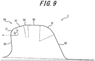
- FIG. 9 schematically illustrates the shape of a thread groove 2 in a third embodiment of the present disclosure.
- the thread groove 2 has a straight thread bottom portion 90 parallel to the taper of the female thread portion.
- the straight thread bottom portion 90 may be directly connected to a corner portion 70 on the stabbing flank side as illustrated in FIG. 9 .
- the corner portion 50 on the load flank side includes a third arc portion 54 between the second arc portion 52 and the straight thread bottom portion 90.
- a third arc portion 54 like this, the second arc portion 52 and the straight thread bottom portion 90 can be smoothly connected via the third arc portion 54.
- the others may be the same as in the first and second embodiments.
- the second arc portion 52 and the third arc portion 54 are directly connected in the embodiment illustrated in FIG. 9 , the second arc portion 52 and the third arc portion 54 may be connected via a straight portion.
- the curvature radius of the third arc portion 54 is not particularly limited, but it is preferably larger than the curvature radius of the first arc portion 51.
- the curvature radius of the third arc portion 54 may be, for example, 0.010 inches to 0.200 inches.
- the straight thread bottom portion 90 may be provided even if there is no third arc portion 54. In that case, the second arc portion 52 and the straight thread bottom portion 90 may be directly connected.
- FIG. 10 schematically illustrates the shape of a thread groove 2 in a fourth embodiment of the present disclosure.
- the thread groove 2 has a straight thread bottom portion 90 parallel to the taper of the female thread portion, as in the third embodiment.
- a corner portion 50 on the load flank side includes a first arc portion 51 directly connected to a load flank 60, a second arc portion 52 connected to the first arc portion 51 via a straight portion 53, and a third arc portion 54 directly connected to the second arc portion.
- the load flank 60, the first arc portion 51, the straight portion 53, the second arc portion 52, and the third arc portion 54 are connected in this order.
- the others may be the same as in the first to third embodiments.
- a steel pipe with outer diameter 9.625 inches ⁇ thickness 0.545 inches (outer diameter 244.48 mm ⁇ thickness 13.84 mm) was prepared with a steel sample corresponding to Category: 13-5-2, Grade: 110 of API 5 CRA, and the steel pipe was processes to obtain a threaded joint including a pin and a box corresponding to the pin.
- the shape of the thread groove of the obtained threaded joint is as indicated in Table 1.
- the number of threads per inch was 5 (5 TPI), and the thread height was 0.062 inches (1.575 mm).
- the stabbing flank angle was 25 degrees
- the load flank angle was -5 degrees
- the thread taper was 1/16.
- the tensile efficiency was designed to be 110 % or less to suppress the outer diameter of the box.
- the shape of the thread groove refers to the shape before tightening the prepared pin and box.
- the box did not fracture even if the tensile efficiency was 109 % or less. Particularly in Example No. 3, no fracture occurred even when the tensile efficiency was 101 %.
- the box fractured even if the tensile efficiency was increased to 110 %. Even when a second arc portion was provided, the box fractured in a comparative example with a ratio of curvature radius of less than 3, even if the tensile efficiency was increased to 110 %.
- the tensile efficiency should be increased to 116 % under the conditions of Comparative Example No. 6 and to 111 % under the conditions of Comparative Example No. 7.
- the present disclosure can prevent fracture of a box under a tensile load without increasing the outer diameter of the box. Therefore, the present disclosure can solve the conflicting problems of fracture prevention and cost reduction.
Landscapes
- Engineering & Computer Science (AREA)
- General Engineering & Computer Science (AREA)
- Mechanical Engineering (AREA)
- Geology (AREA)
- Life Sciences & Earth Sciences (AREA)
- Mining & Mineral Resources (AREA)
- Environmental & Geological Engineering (AREA)
- Fluid Mechanics (AREA)
- General Life Sciences & Earth Sciences (AREA)
- Geochemistry & Mineralogy (AREA)
- Physics & Mathematics (AREA)
- Non-Disconnectible Joints And Screw-Threaded Joints (AREA)
- Earth Drilling (AREA)
Applications Claiming Priority (2)
| Application Number | Priority Date | Filing Date | Title |
|---|---|---|---|
| JP2019236848 | 2019-12-26 | ||
| PCT/JP2020/034513 WO2021131177A1 (fr) | 2019-12-26 | 2020-09-11 | Raccord fileté pour tubes |
Publications (3)
| Publication Number | Publication Date |
|---|---|
| EP4083369A1 true EP4083369A1 (fr) | 2022-11-02 |
| EP4083369A4 EP4083369A4 (fr) | 2023-01-18 |
| EP4083369B1 EP4083369B1 (fr) | 2024-08-14 |
Family
ID=76507927
Family Applications (1)
| Application Number | Title | Priority Date | Filing Date |
|---|---|---|---|
| EP20905534.2A Active EP4083369B1 (fr) | 2019-12-26 | 2020-09-11 | Raccord fileté pour tuyaux |
Country Status (9)
| Country | Link |
|---|---|
| US (1) | US11905765B2 (fr) |
| EP (1) | EP4083369B1 (fr) |
| JP (1) | JP7184169B2 (fr) |
| CN (2) | CN113048297B (fr) |
| AR (1) | AR120888A1 (fr) |
| ES (1) | ES2993883T3 (fr) |
| MX (1) | MX2022008025A (fr) |
| SA (1) | SA522433124B1 (fr) |
| WO (1) | WO2021131177A1 (fr) |
Families Citing this family (2)
| Publication number | Priority date | Publication date | Assignee | Title |
|---|---|---|---|---|
| MX2022008025A (es) | 2019-12-26 | 2022-07-27 | Jfe Steel Corp | Junta roscada para tuberias. |
| WO2026078758A1 (fr) * | 2024-10-07 | 2026-04-16 | Jfeスチール株式会社 | Joint fileté pour tubes en acier |
Family Cites Families (19)
| Publication number | Priority date | Publication date | Assignee | Title |
|---|---|---|---|---|
| US4113290A (en) * | 1975-11-06 | 1978-09-12 | Tsukamoto Seiki Co., Ltd. | Pressure tight joint for a large diameter casing |
| JP2705506B2 (ja) * | 1993-03-24 | 1998-01-28 | 住友金属工業株式会社 | 油井管用ねじ継手 |
| US6030004A (en) | 1997-12-08 | 2000-02-29 | Shaw Industries | High torque threaded tool joint for drill pipe and other drill stem components |
| FR2807138B1 (fr) * | 2000-03-31 | 2002-05-17 | Vallourec Mannesmann Oil & Gas | Element filete tubulaire pour joint filete tubulaire resistant a la fatigue et joint filete tubulaire resultant |
| WO2001094831A1 (fr) * | 2000-06-07 | 2001-12-13 | Sumitomo Metal Industries, Ltd. | Liaison a filetage conique |
| US6755447B2 (en) * | 2001-08-24 | 2004-06-29 | The Technologies Alliance, Inc. | Production riser connector |
| CN202007937U (zh) * | 2011-02-23 | 2011-10-12 | 宝山钢铁股份有限公司 | 一种公端对顶油套管连接结构 |
| US8668232B2 (en) | 2011-12-09 | 2014-03-11 | Tenaris Connections Limited | Threaded connection with improved root thread profile |
| CN103362459B (zh) | 2013-08-03 | 2015-06-17 | 无锡西姆莱斯石油专用管制造有限公司 | 一种弧形锥面密封变牙宽楔型接箍结构及油井管结构 |
| JP5971264B2 (ja) | 2014-01-10 | 2016-08-17 | Jfeスチール株式会社 | 極厚肉油井管用ねじ継手 |
| JP5967113B2 (ja) | 2014-01-24 | 2016-08-10 | Jfeスチール株式会社 | 管のねじ継手 |
| US20170122468A1 (en) * | 2014-05-30 | 2017-05-04 | Nippon Steel & Sumitomo Metal Corporation | Threaded joint for steel pipes |
| US9874058B2 (en) | 2014-07-31 | 2018-01-23 | Baker Hughes, A Ge Company, Llc | Fatigue resistant thread profile with combined curve rounding |
| US20170321826A1 (en) | 2014-08-12 | 2017-11-09 | Patented Products LLC | Single lead wedgethread connection |
| JP2017072187A (ja) | 2015-10-07 | 2017-04-13 | Jfeスチール株式会社 | 油井管ケーシング用ねじ継手 |
| UA122027C2 (uk) * | 2016-08-24 | 2020-08-25 | ДжФЕ СТІЛ КОРПОРЕЙШН | Різьбове з'єднання для трубних виробів нафтопромислового сортаменту |
| US11125361B2 (en) * | 2018-03-01 | 2021-09-21 | Mitchell Z. Dziekonski | Thread form and threaded article |
| RU2756365C9 (ru) * | 2018-08-21 | 2021-10-06 | Ниппон Стил Корпорейшн | Резьбовое соединение для стальных труб |
| MX2022008025A (es) | 2019-12-26 | 2022-07-27 | Jfe Steel Corp | Junta roscada para tuberias. |
-
2020
- 2020-09-11 MX MX2022008025A patent/MX2022008025A/es unknown
- 2020-09-11 WO PCT/JP2020/034513 patent/WO2021131177A1/fr not_active Ceased
- 2020-09-11 EP EP20905534.2A patent/EP4083369B1/fr active Active
- 2020-09-11 US US17/757,722 patent/US11905765B2/en active Active
- 2020-09-11 JP JP2021513477A patent/JP7184169B2/ja active Active
- 2020-09-11 ES ES20905534T patent/ES2993883T3/es active Active
- 2020-12-11 CN CN202011451231.6A patent/CN113048297B/zh active Active
- 2020-12-11 CN CN202022984043.1U patent/CN215596629U/zh active Active
- 2020-12-23 AR ARP200103632A patent/AR120888A1/es active IP Right Grant
-
2022
- 2022-06-23 SA SA522433124A patent/SA522433124B1/ar unknown
Also Published As
| Publication number | Publication date |
|---|---|
| CN113048297B (zh) | 2022-11-15 |
| WO2021131177A1 (fr) | 2021-07-01 |
| EP4083369A4 (fr) | 2023-01-18 |
| JPWO2021131177A1 (ja) | 2021-12-23 |
| CN215596629U (zh) | 2022-01-21 |
| ES2993883T3 (en) | 2025-01-13 |
| SA522433124B1 (ar) | 2023-02-19 |
| EP4083369B1 (fr) | 2024-08-14 |
| BR112022012399A2 (pt) | 2022-08-30 |
| US20230044251A1 (en) | 2023-02-09 |
| JP7184169B2 (ja) | 2022-12-06 |
| AR120888A1 (es) | 2022-03-30 |
| CN113048297A (zh) | 2021-06-29 |
| US11905765B2 (en) | 2024-02-20 |
| MX2022008025A (es) | 2022-07-27 |
Similar Documents
| Publication | Publication Date | Title |
|---|---|---|
| EP3418617B1 (fr) | Joint fileté pour conduite de puits de pétrole | |
| EP3064818B1 (fr) | Raccord avec filetage pour tubes de puits de pétrole à parois épaisses | |
| EP4012239B1 (fr) | Raccord fileté pour tuyau en acier | |
| EP3486540B1 (fr) | Raccord fileté pour tuyau d'acier de puits de pétrole | |
| CN106014278B (zh) | 管螺纹接头 | |
| EP3392543B1 (fr) | Joint fileté pour tube en acier | |
| EP2682658A1 (fr) | Raccord fileté pour tube | |
| EP3708892A1 (fr) | Raccord fileté pour tuyaux en acier | |
| US20200332929A1 (en) | Threaded joint for steel pipes | |
| EP4083369B1 (fr) | Raccord fileté pour tuyaux | |
| EP3904745B1 (fr) | Connexion filetée pour tuyau en acier | |
| EP3763981B1 (fr) | Raccord fileté pour tuyau de puits de pétrole | |
| EP3098496B1 (fr) | Raccord à vis pour tuyau | |
| CN108952595B (zh) | 一种气密封螺纹接头 | |
| JP2001182874A (ja) | 油井管用ねじ継手およびその製造方法 | |
| RU2788781C1 (ru) | Резьбовое соединение для труб | |
| EA043019B1 (ru) | Резьбовое соединение |
Legal Events
| Date | Code | Title | Description |
|---|---|---|---|
| STAA | Information on the status of an ep patent application or granted ep patent |
Free format text: STATUS: THE INTERNATIONAL PUBLICATION HAS BEEN MADE |
|
| PUAI | Public reference made under article 153(3) epc to a published international application that has entered the european phase |
Free format text: ORIGINAL CODE: 0009012 |
|
| STAA | Information on the status of an ep patent application or granted ep patent |
Free format text: STATUS: REQUEST FOR EXAMINATION WAS MADE |
|
| 17P | Request for examination filed |
Effective date: 20220722 |
|
| AK | Designated contracting states |
Kind code of ref document: A1 Designated state(s): AL AT BE BG CH CY CZ DE DK EE ES FI FR GB GR HR HU IE IS IT LI LT LU LV MC MK MT NL NO PL PT RO RS SE SI SK SM TR |
|
| A4 | Supplementary search report drawn up and despatched |
Effective date: 20221221 |
|
| RIC1 | Information provided on ipc code assigned before grant |
Ipc: F16L 15/06 20060101ALI20221215BHEP Ipc: E21B 17/042 20060101AFI20221215BHEP |
|
| DAV | Request for validation of the european patent (deleted) | ||
| DAX | Request for extension of the european patent (deleted) | ||
| GRAP | Despatch of communication of intention to grant a patent |
Free format text: ORIGINAL CODE: EPIDOSNIGR1 |
|
| STAA | Information on the status of an ep patent application or granted ep patent |
Free format text: STATUS: GRANT OF PATENT IS INTENDED |
|
| INTG | Intention to grant announced |
Effective date: 20240307 |
|
| GRAS | Grant fee paid |
Free format text: ORIGINAL CODE: EPIDOSNIGR3 |
|
| GRAA | (expected) grant |
Free format text: ORIGINAL CODE: 0009210 |
|
| STAA | Information on the status of an ep patent application or granted ep patent |
Free format text: STATUS: THE PATENT HAS BEEN GRANTED |
|
| AK | Designated contracting states |
Kind code of ref document: B1 Designated state(s): AL AT BE BG CH CY CZ DE DK EE ES FI FR GB GR HR HU IE IS IT LI LT LU LV MC MK MT NL NO PL PT RO RS SE SI SK SM TR |
|
| REG | Reference to a national code |
Ref country code: GB Ref legal event code: FG4D |
|
| REG | Reference to a national code |
Ref country code: CH Ref legal event code: EP |
|
| REG | Reference to a national code |
Ref country code: DE Ref legal event code: R096 Ref document number: 602020035974 Country of ref document: DE |
|
| REG | Reference to a national code |
Ref country code: IE Ref legal event code: FG4D |
|
| REG | Reference to a national code |
Ref country code: LT Ref legal event code: MG9D |
|
| REG | Reference to a national code |
Ref country code: NL Ref legal event code: MP Effective date: 20240814 |
|
| REG | Reference to a national code |
Ref country code: ES Ref legal event code: FG2A Ref document number: 2993883 Country of ref document: ES Kind code of ref document: T3 Effective date: 20250113 |
|
| PG25 | Lapsed in a contracting state [announced via postgrant information from national office to epo] |
Ref country code: NO Free format text: LAPSE BECAUSE OF FAILURE TO SUBMIT A TRANSLATION OF THE DESCRIPTION OR TO PAY THE FEE WITHIN THE PRESCRIBED TIME-LIMIT Effective date: 20241114 |
|
| PG25 | Lapsed in a contracting state [announced via postgrant information from national office to epo] |
Ref country code: FI Free format text: LAPSE BECAUSE OF FAILURE TO SUBMIT A TRANSLATION OF THE DESCRIPTION OR TO PAY THE FEE WITHIN THE PRESCRIBED TIME-LIMIT Effective date: 20240814 Ref country code: PT Free format text: LAPSE BECAUSE OF FAILURE TO SUBMIT A TRANSLATION OF THE DESCRIPTION OR TO PAY THE FEE WITHIN THE PRESCRIBED TIME-LIMIT Effective date: 20241216 Ref country code: NL Free format text: LAPSE BECAUSE OF FAILURE TO SUBMIT A TRANSLATION OF THE DESCRIPTION OR TO PAY THE FEE WITHIN THE PRESCRIBED TIME-LIMIT Effective date: 20240814 Ref country code: PL Free format text: LAPSE BECAUSE OF FAILURE TO SUBMIT A TRANSLATION OF THE DESCRIPTION OR TO PAY THE FEE WITHIN THE PRESCRIBED TIME-LIMIT Effective date: 20240814 Ref country code: GR Free format text: LAPSE BECAUSE OF FAILURE TO SUBMIT A TRANSLATION OF THE DESCRIPTION OR TO PAY THE FEE WITHIN THE PRESCRIBED TIME-LIMIT Effective date: 20241115 |
|
| PG25 | Lapsed in a contracting state [announced via postgrant information from national office to epo] |
Ref country code: BG Free format text: LAPSE BECAUSE OF FAILURE TO SUBMIT A TRANSLATION OF THE DESCRIPTION OR TO PAY THE FEE WITHIN THE PRESCRIBED TIME-LIMIT Effective date: 20240814 |
|
| PG25 | Lapsed in a contracting state [announced via postgrant information from national office to epo] |
Ref country code: LV Free format text: LAPSE BECAUSE OF FAILURE TO SUBMIT A TRANSLATION OF THE DESCRIPTION OR TO PAY THE FEE WITHIN THE PRESCRIBED TIME-LIMIT Effective date: 20240814 |
|
| PG25 | Lapsed in a contracting state [announced via postgrant information from national office to epo] |
Ref country code: IS Free format text: LAPSE BECAUSE OF FAILURE TO SUBMIT A TRANSLATION OF THE DESCRIPTION OR TO PAY THE FEE WITHIN THE PRESCRIBED TIME-LIMIT Effective date: 20241214 |
|
| PG25 | Lapsed in a contracting state [announced via postgrant information from national office to epo] |
Ref country code: HR Free format text: LAPSE BECAUSE OF FAILURE TO SUBMIT A TRANSLATION OF THE DESCRIPTION OR TO PAY THE FEE WITHIN THE PRESCRIBED TIME-LIMIT Effective date: 20240814 |
|
| PG25 | Lapsed in a contracting state [announced via postgrant information from national office to epo] |
Ref country code: RS Free format text: LAPSE BECAUSE OF FAILURE TO SUBMIT A TRANSLATION OF THE DESCRIPTION OR TO PAY THE FEE WITHIN THE PRESCRIBED TIME-LIMIT Effective date: 20241114 |
|
| PG25 | Lapsed in a contracting state [announced via postgrant information from national office to epo] |
Ref country code: RS Free format text: LAPSE BECAUSE OF FAILURE TO SUBMIT A TRANSLATION OF THE DESCRIPTION OR TO PAY THE FEE WITHIN THE PRESCRIBED TIME-LIMIT Effective date: 20241114 Ref country code: PT Free format text: LAPSE BECAUSE OF FAILURE TO SUBMIT A TRANSLATION OF THE DESCRIPTION OR TO PAY THE FEE WITHIN THE PRESCRIBED TIME-LIMIT Effective date: 20241216 Ref country code: PL Free format text: LAPSE BECAUSE OF FAILURE TO SUBMIT A TRANSLATION OF THE DESCRIPTION OR TO PAY THE FEE WITHIN THE PRESCRIBED TIME-LIMIT Effective date: 20240814 Ref country code: NO Free format text: LAPSE BECAUSE OF FAILURE TO SUBMIT A TRANSLATION OF THE DESCRIPTION OR TO PAY THE FEE WITHIN THE PRESCRIBED TIME-LIMIT Effective date: 20241114 Ref country code: NL Free format text: LAPSE BECAUSE OF FAILURE TO SUBMIT A TRANSLATION OF THE DESCRIPTION OR TO PAY THE FEE WITHIN THE PRESCRIBED TIME-LIMIT Effective date: 20240814 Ref country code: LV Free format text: LAPSE BECAUSE OF FAILURE TO SUBMIT A TRANSLATION OF THE DESCRIPTION OR TO PAY THE FEE WITHIN THE PRESCRIBED TIME-LIMIT Effective date: 20240814 Ref country code: IS Free format text: LAPSE BECAUSE OF FAILURE TO SUBMIT A TRANSLATION OF THE DESCRIPTION OR TO PAY THE FEE WITHIN THE PRESCRIBED TIME-LIMIT Effective date: 20241214 Ref country code: HR Free format text: LAPSE BECAUSE OF FAILURE TO SUBMIT A TRANSLATION OF THE DESCRIPTION OR TO PAY THE FEE WITHIN THE PRESCRIBED TIME-LIMIT Effective date: 20240814 Ref country code: GR Free format text: LAPSE BECAUSE OF FAILURE TO SUBMIT A TRANSLATION OF THE DESCRIPTION OR TO PAY THE FEE WITHIN THE PRESCRIBED TIME-LIMIT Effective date: 20241115 Ref country code: FI Free format text: LAPSE BECAUSE OF FAILURE TO SUBMIT A TRANSLATION OF THE DESCRIPTION OR TO PAY THE FEE WITHIN THE PRESCRIBED TIME-LIMIT Effective date: 20240814 Ref country code: BG Free format text: LAPSE BECAUSE OF FAILURE TO SUBMIT A TRANSLATION OF THE DESCRIPTION OR TO PAY THE FEE WITHIN THE PRESCRIBED TIME-LIMIT Effective date: 20240814 |
|
| PG25 | Lapsed in a contracting state [announced via postgrant information from national office to epo] |
Ref country code: DK Free format text: LAPSE BECAUSE OF FAILURE TO SUBMIT A TRANSLATION OF THE DESCRIPTION OR TO PAY THE FEE WITHIN THE PRESCRIBED TIME-LIMIT Effective date: 20240814 Ref country code: RO Free format text: LAPSE BECAUSE OF FAILURE TO SUBMIT A TRANSLATION OF THE DESCRIPTION OR TO PAY THE FEE WITHIN THE PRESCRIBED TIME-LIMIT Effective date: 20240814 Ref country code: SM Free format text: LAPSE BECAUSE OF FAILURE TO SUBMIT A TRANSLATION OF THE DESCRIPTION OR TO PAY THE FEE WITHIN THE PRESCRIBED TIME-LIMIT Effective date: 20240814 |
|
| PG25 | Lapsed in a contracting state [announced via postgrant information from national office to epo] |
Ref country code: EE Free format text: LAPSE BECAUSE OF FAILURE TO SUBMIT A TRANSLATION OF THE DESCRIPTION OR TO PAY THE FEE WITHIN THE PRESCRIBED TIME-LIMIT Effective date: 20240814 |
|
| PG25 | Lapsed in a contracting state [announced via postgrant information from national office to epo] |
Ref country code: CZ Free format text: LAPSE BECAUSE OF FAILURE TO SUBMIT A TRANSLATION OF THE DESCRIPTION OR TO PAY THE FEE WITHIN THE PRESCRIBED TIME-LIMIT Effective date: 20240814 |
|
| PG25 | Lapsed in a contracting state [announced via postgrant information from national office to epo] |
Ref country code: SK Free format text: LAPSE BECAUSE OF FAILURE TO SUBMIT A TRANSLATION OF THE DESCRIPTION OR TO PAY THE FEE WITHIN THE PRESCRIBED TIME-LIMIT Effective date: 20240814 |
|
| REG | Reference to a national code |
Ref country code: CH Ref legal event code: PL |
|
| REG | Reference to a national code |
Ref country code: DE Ref legal event code: R097 Ref document number: 602020035974 Country of ref document: DE |
|
| PG25 | Lapsed in a contracting state [announced via postgrant information from national office to epo] |
Ref country code: LU Free format text: LAPSE BECAUSE OF NON-PAYMENT OF DUE FEES Effective date: 20240911 |
|
| PLBE | No opposition filed within time limit |
Free format text: ORIGINAL CODE: 0009261 |
|
| STAA | Information on the status of an ep patent application or granted ep patent |
Free format text: STATUS: NO OPPOSITION FILED WITHIN TIME LIMIT |
|
| PG25 | Lapsed in a contracting state [announced via postgrant information from national office to epo] |
Ref country code: MC Free format text: LAPSE BECAUSE OF FAILURE TO SUBMIT A TRANSLATION OF THE DESCRIPTION OR TO PAY THE FEE WITHIN THE PRESCRIBED TIME-LIMIT Effective date: 20240814 |
|
| REG | Reference to a national code |
Ref country code: BE Ref legal event code: MM Effective date: 20240930 |
|
| PG25 | Lapsed in a contracting state [announced via postgrant information from national office to epo] |
Ref country code: IT Free format text: LAPSE BECAUSE OF NON-PAYMENT OF DUE FEES Effective date: 20240911 Ref country code: BE Free format text: LAPSE BECAUSE OF NON-PAYMENT OF DUE FEES Effective date: 20240930 |
|
| 26N | No opposition filed |
Effective date: 20250515 |
|
| PG25 | Lapsed in a contracting state [announced via postgrant information from national office to epo] |
Ref country code: CH Free format text: LAPSE BECAUSE OF NON-PAYMENT OF DUE FEES Effective date: 20240930 |
|
| PG25 | Lapsed in a contracting state [announced via postgrant information from national office to epo] |
Ref country code: IE Free format text: LAPSE BECAUSE OF NON-PAYMENT OF DUE FEES Effective date: 20240911 |
|
| PG25 | Lapsed in a contracting state [announced via postgrant information from national office to epo] |
Ref country code: SE Free format text: LAPSE BECAUSE OF FAILURE TO SUBMIT A TRANSLATION OF THE DESCRIPTION OR TO PAY THE FEE WITHIN THE PRESCRIBED TIME-LIMIT Effective date: 20240814 |
|
| PGFP | Annual fee paid to national office [announced via postgrant information from national office to epo] |
Ref country code: DE Payment date: 20250730 Year of fee payment: 6 |
|
| PGFP | Annual fee paid to national office [announced via postgrant information from national office to epo] |
Ref country code: GB Payment date: 20250731 Year of fee payment: 6 |
|
| PGFP | Annual fee paid to national office [announced via postgrant information from national office to epo] |
Ref country code: AT Payment date: 20250827 Year of fee payment: 6 Ref country code: FR Payment date: 20250808 Year of fee payment: 6 |
|
| PG25 | Lapsed in a contracting state [announced via postgrant information from national office to epo] |
Ref country code: CY Free format text: LAPSE BECAUSE OF FAILURE TO SUBMIT A TRANSLATION OF THE DESCRIPTION OR TO PAY THE FEE WITHIN THE PRESCRIBED TIME-LIMIT; INVALID AB INITIO Effective date: 20200911 |
|
| PGFP | Annual fee paid to national office [announced via postgrant information from national office to epo] |
Ref country code: ES Payment date: 20251013 Year of fee payment: 6 |
|
| PG25 | Lapsed in a contracting state [announced via postgrant information from national office to epo] |
Ref country code: HU Free format text: LAPSE BECAUSE OF FAILURE TO SUBMIT A TRANSLATION OF THE DESCRIPTION OR TO PAY THE FEE WITHIN THE PRESCRIBED TIME-LIMIT; INVALID AB INITIO Effective date: 20200911 |