EP4083516A1 - Hotte portative - Google Patents
Hotte portative Download PDFInfo
- Publication number
- EP4083516A1 EP4083516A1 EP22153079.3A EP22153079A EP4083516A1 EP 4083516 A1 EP4083516 A1 EP 4083516A1 EP 22153079 A EP22153079 A EP 22153079A EP 4083516 A1 EP4083516 A1 EP 4083516A1
- Authority
- EP
- European Patent Office
- Prior art keywords
- unit
- discharging
- present disclosure
- fan
- columnar
- Prior art date
- Legal status (The legal status is an assumption and is not a legal conclusion. Google has not performed a legal analysis and makes no representation as to the accuracy of the status listed.)
- Granted
Links
Images






Classifications
-
- F—MECHANICAL ENGINEERING; LIGHTING; HEATING; WEAPONS; BLASTING
- F24—HEATING; RANGES; VENTILATING
- F24C—DOMESTIC STOVES OR RANGES ; DETAILS OF DOMESTIC STOVES OR RANGES, OF GENERAL APPLICATION
- F24C15/00—Details
- F24C15/20—Removing cooking fumes
- F24C15/2078—Removing cooking fumes movable
-
- F—MECHANICAL ENGINEERING; LIGHTING; HEATING; WEAPONS; BLASTING
- F04—POSITIVE - DISPLACEMENT MACHINES FOR LIQUIDS; PUMPS FOR LIQUIDS OR ELASTIC FLUIDS
- F04D—NON-POSITIVE-DISPLACEMENT PUMPS
- F04D25/00—Pumping installations or systems
- F04D25/02—Units comprising pumps and their driving means
- F04D25/06—Units comprising pumps and their driving means the pump being electrically driven
-
- F—MECHANICAL ENGINEERING; LIGHTING; HEATING; WEAPONS; BLASTING
- F04—POSITIVE - DISPLACEMENT MACHINES FOR LIQUIDS; PUMPS FOR LIQUIDS OR ELASTIC FLUIDS
- F04D—NON-POSITIVE-DISPLACEMENT PUMPS
- F04D29/00—Details, component parts, or accessories
- F04D29/26—Rotors specially for elastic fluids
- F04D29/263—Rotors specially for elastic fluids mounting fan or blower rotors on shafts
-
- F—MECHANICAL ENGINEERING; LIGHTING; HEATING; WEAPONS; BLASTING
- F04—POSITIVE - DISPLACEMENT MACHINES FOR LIQUIDS; PUMPS FOR LIQUIDS OR ELASTIC FLUIDS
- F04D—NON-POSITIVE-DISPLACEMENT PUMPS
- F04D29/00—Details, component parts, or accessories
- F04D29/60—Mounting; Assembling; Disassembling
- F04D29/601—Mounting; Assembling; Disassembling specially adapted for elastic fluid pumps
-
- F—MECHANICAL ENGINEERING; LIGHTING; HEATING; WEAPONS; BLASTING
- F24—HEATING; RANGES; VENTILATING
- F24C—DOMESTIC STOVES OR RANGES ; DETAILS OF DOMESTIC STOVES OR RANGES, OF GENERAL APPLICATION
- F24C15/00—Details
- F24C15/20—Removing cooking fumes
- F24C15/2078—Removing cooking fumes movable
- F24C15/2092—Removing cooking fumes movable extendable or pivotable
-
- F—MECHANICAL ENGINEERING; LIGHTING; HEATING; WEAPONS; BLASTING
- F24—HEATING; RANGES; VENTILATING
- F24F—AIR-CONDITIONING; AIR-HUMIDIFICATION; VENTILATION; USE OF AIR CURRENTS FOR SCREENING
- F24F11/00—Control or safety arrangements
- F24F11/88—Electrical aspects, e.g. circuits
-
- F—MECHANICAL ENGINEERING; LIGHTING; HEATING; WEAPONS; BLASTING
- F24—HEATING; RANGES; VENTILATING
- F24F—AIR-CONDITIONING; AIR-HUMIDIFICATION; VENTILATION; USE OF AIR CURRENTS FOR SCREENING
- F24F7/00—Ventilation
- F24F7/007—Ventilation with forced flow
-
- F—MECHANICAL ENGINEERING; LIGHTING; HEATING; WEAPONS; BLASTING
- F05—INDEXING SCHEMES RELATING TO ENGINES OR PUMPS IN VARIOUS SUBCLASSES OF CLASSES F01-F04
- F05D—INDEXING SCHEME FOR ASPECTS RELATING TO NON-POSITIVE-DISPLACEMENT MACHINES OR ENGINES, GAS-TURBINES OR JET-PROPULSION PLANTS
- F05D2210/00—Working fluids
- F05D2210/10—Kind or type
- F05D2210/12—Kind or type gaseous, i.e. compressible
Definitions
- the present disclosure relates generally to a portable hood. More particularly, the present disclosure relates to a portable hood which is used while food is cooked.
- a hood is installed above a heating appliance for cooking such as a gas stove or induction cooker, and draws odors, water vapor, oil vapor, or fine dust thereto (hereinafter, referred to as "oil vapor") which is generated during the cooking of food by the heating appliance for cooking and discharges it to the outside.
- the installation position of the heating appliance for cooking such as a gas stove or induction cooker is fixed, so the installation position of the hood installed above the heating appliance for cooking is also generally fixed.
- a fixing hood installed above the heating appliance for cooking is generally installed at a position somewhat higher than the heating appliance for a kitchen structure or the convenience of cooking. Accordingly, a distance between an actual cooking location and the sucking unit of the fixing hood is far, so oil vapor generated during cooking may not all be removed through the hood.
- the oil vapor not removed by the hood flows into a room and causes odor or causes stains on a wall or furniture by being attached thereto.
- the existing fixing hood can be used in a fixed heating appliance such as a gas stove or induction cooker but cannot be used when meat is grilled by a portable burner placed on a dining table or at living room, or when cooking is performed outdoors as in camping.
- the present disclosure has been made keeping in mind the above problems occurring in the related art, and the present disclosure is intended to propose a portable hood which is changeable in an installation position.
- the present disclosure is intended to propose a portable hood which maintains a stable standing state to remove the possibility of tipping over during use such that a stable cooking can be performed.
- the present disclosure is intended to propose a portable hood which draws oil vapor generated during cooking thereto at a position adjacent to an upper part of a cooking utensil such as a pot such that the efficiency of drawing the oil vapor is increased.
- the present disclosure is intended to propose a portable hood in which a sucking unit is adjusted such that the sucking unit is placed above a cooking utensil according to the height or position of the cooking utensil.
- the present disclosure is intended to propose a portable hood in which oil vapor is prevented from bypassing the sucking unit without being introduced to the sucking unit.
- the present disclosure is intended to propose a portable hood in which oil vapor is introduced through the sucking unit and discharged upward such that the oil vapor is efficiently removed through the cooperation of the portable hood with a fixing hood installed in a kitchen.
- the present disclosure is intended to propose a portable hood in which main components are easily disassembled and then are washed such that the cleanliness of the main components is maintained.
- the present disclosure is intended to propose a portable hood which in addition to a function of removing oil vapor during cooking, has an air cleaning function.
- a portable hood may include a base unit, a head unit, a columnar unit, and a drawing-force generation part.
- the base unit according to the embodiment of the present disclosure may sit on a foundation.
- the head unit according to the embodiment of the present disclosure may introduce air thereto and may discharge the introduced air to the outside.
- the columnar unit according to the embodiment of the present disclosure may connect the head unit with the base unit such that the head unit is spaced upward apart from the base unit.
- the columnar unit may be coupled to the head unit to be biased to a horizontal side thereof.
- the drawing-force generation part may be installed in the head unit and may generate air-drawing force.
- the drawing-force generation part may be located in the head unit such that the drawing-force generation part is biased to a horizontal side of the head unit to correspond to the columnar unit.
- the head unit may include a sucking unit and a discharging unit.
- Air may be introduced to the sucking unit according to the embodiment of the present disclosure, and the air introduced through the sucking unit may be discharged to the outside through the discharging unit.
- the sucking unit and the discharging unit may be formed to be eccentric to each other in a horizontal direction relative to a vertical direction.
- the discharging unit may be located to be biased in a direction toward the columnar unit from the sucking unit.
- the columnar unit according to the embodiment of the present disclosure may be rotatably coupled to the base unit such that the sucking unit of the head unit is rotatable side to side in a horizontal direction.
- the drawing-force generation part may be installed in the discharging unit and may include a discharging fan configured to generate air-drawing force for introducing air to the discharging unit.
- the discharging fan may be installed in the head unit such that the discharging fan is located at the upper side of the columnar unit.
- drawing-force generation part may further include a fan motor configured to rotate the discharging fan.
- the fan motor may be installed in the head unit such that the fan motor is located at the upper side of the columnar unit.
- the discharging fan and a rotating shaft of the fan motor may be installed vertically, and the discharging fan and the fan motor may be installed in the head unit such that the rotating shaft of the fan motor is located inside the columnar unit.
- the fan motor, the discharging fan, and the columnar unit may be installed such that the central axes of the fan motor, the discharging fan, and the columnar unit correspond to each other.
- the head unit may include a head main body and a flow-path portion.
- the sucking unit and the discharging unit may be formed in the head unit according to the embodiment of the present disclosure such that the sucking unit and the discharging unit are eccentric to each other in a horizontal direction. Furthermore, the flow-path portion may be provided inside the head main body and may include a flow path formed therein such that air introduced through the sucking unit flows to the discharging unit through the flow path.
- the discharging fan and the fan motor may be vertically arranged with the flow-path portion placed between the discharging fan and the fan motor.
- the flow-path portion may include a sucking inlet, a filter discharging hole, and an inner flow path.
- the sucking inlet may be open toward the sucking unit
- the filter discharging hole may be open toward the discharging unit.
- the inner flow path may communicate the sucking inlet with the filter discharging hole in a horizontal direction.
- the sucking inlet and the filter discharging hole may be formed in the flow-path portion such that the sucking inlet and the filter discharging hole do not vertically overlap.
- the discharging fan and the fan motor may be installed in the head unit such that the discharging fan and the fan motor are located at the upper and lower sides, respectively, of the filter discharging hole.
- the columnar unit according to the embodiment of the present disclosure may be coupled to the base unit such that the columnar unit is horizontally eccentric to the base unit.
- the width of the base unit in the short length direction of the horizontal cross section of each of the base unit and the head unit, may be equal to or wider than the width of the head unit.
- the portable hood according to the embodiment of the present disclosure may further include a weight plate.
- the weight plate may be provided inside the base unit and may prevent the columnar unit and the head unit from tipping over.
- the weight plate may be made of metal.
- the portable hood according to the embodiment of the present disclosure may further include a battery module.
- the battery module may be installed inside the columnar unit and may supply actuating power required for operating the fan motor.
- the battery module may be installed at the lower side of the inside of the columnar unit.
- each of a plurality of battery modules may be horizontally arranged inside the columnar unit by standing.
- the portable hood according to the present disclosure may have at least one following effect.
- the drawing-force generation part generating air-drawing force may be located eccentrically to a side of the columnar unit, and the center of weight of the portable hood may be formed at the side of the columnar unit, thereby preventing the tipping over of the portable hood.
- components such as a weight plate and a battery module may be arranged in the base unit or the columnar unit such that the center of weight of the portable hood is located at the columnar unit or a lower portion of the portable hood, thereby enabling the stable standing of the portable hood such that the portable hood is prevented from tipping over.
- the sucking unit and the discharging unit may be formed at eccentric positions in a horizontal direction, thereby removing the bypassing of air occurring when the sucking unit and the discharging unit are positioned on the same axis in a vertical direction and improving the efficiency of drawing and discharging air.
- the sucking unit and the discharging unit may be formed at eccentric positions in a horizontal direction, the flow of air introduced to the sucking unit and the flow of air discharged from the discharging unit may not affect each other, thereby improving the efficiency of drawing and discharging air.
- the head unit may be provided to rotate horizontally relative to the base unit, and the sucking unit may be adjusted to be located adjacently to the upper portion of a cooking utensil according to a cooking environment such as the position of a burner being used. Accordingly, the portable hood may draw oil vapor thereto at the position adjacent to the upper portion of the cooking utensil, thereby increasing the efficiency of drawing the oil vapor.
- the discharging unit may be configured to discharge oil vapor in an upward direction, and the oil vapor may be discharged in a direction toward a fixing hood, thereby effectively removing the oil vapor generated during cooking in cooperation with the fixing hood.
- the fan motor configured to rotate the discharging fan may be located under a flow path in which oil vapor flows, thereby preventing the contamination of the fan motor due to the oil vapor. Furthermore, due to the prevention of the contamination of the fan motor, the fan motor may not be required to be disassembled during the dissembling of the portable hood to wash the portable hood, thereby simplifying the disassembling and washing of the portable hood.
- the head main body may be removed from the casing main body and the upper casing, and the flow-path portion communicating the sucking unit with the discharging unit may be removed from the casing main body, thereby enabling the washing of the flow-path portion in which the oil vapor flows.
- the fan housing receiving the discharging fan may protrude from the head unit, thereby slimming the entire vertical thickness of the head main body receiving the discharging fan and the fan motor.
- the disassembling of the head unit may be easy, thereby facilitating the washing and replacement of the discharging fan, the flow-path portion, and the purification filter such as the deodorization filter installed in the head unit.
- the lower casing may be removed from the casing main body, thereby facilitating the replacement of the oil mist filter provided as a roll filter through a hinged coupling between the first casing main body and the second casing main body.
- an end of the oil mist filter discharged to the upper side of the head unit may be configured to be discharged to the discharging unit located at a side opposite to a burner, thereby preventing accidents which may occur during the discharge of the end of the oil mist filter to the burner.
- the head unit may be configured to have adjustable height, thereby effectively drawing and discharging oil vapor according to cooking utensils having various heights without affecting cooking.
- the purification filter constituting the filter unit may be replaced, thereby functioning as an air purifier by replacing a purification filter used during cooking with the purification filter for air purification.
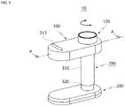
- a portable hood 10 may include a head unit 100, a base unit 200, a columnar unit 300, and a drawing-force generation part 410 and 420 (see FIG. 3 ).
- the base unit 200 may sit on a foundation.
- a shape of the flat surface of the base unit 200 has a shape of an oblong racetrack, but the technical spirit of the present disclosure is not limited thereto.
- the head unit 100 may allow air to be introduced thereto and then may discharge the introduced air to the outside.
- the columnar unit 300 may connect the head unit 100 with the base unit 200 such that the head unit 100 is spaced apart upward from the base unit 200.
- the columnar unit 300 is coupled to the head unit 100 to be horizontally biased.
- the drawing-force generation part 410 and 420 may be installed inside the head unit 100 and may be located to be biased to a horizontal side of the head unit 100 to correspond to the columnar unit 300. Accordingly, although the columnar unit 300 is coupled to the head unit 100 such that the columnar unit 300 is biased horizontally relative to the head unit 100, the center of weight of the portable hood 10 may be formed at the side of the columnar unit 300. Accordingly, the portable hood 10 according to the embodiment of the present disclosure may maintain a stable standing state due to the center of weight of the portable hood formed at the side of the columnar unit 300, so the tipping over of the portable hood 10 may be prevented.
- drawing-force generation part 410 and 420 according to the embodiment of the present disclosure will be described in detail hereinafter.
- the head unit 100 includes the sucking unit 110 and the discharging unit 120.
- Air may be introduced to the sucking unit 110 according to the embodiment of the present disclosure. Furthermore, the air introduced into the sucking unit 110 may be discharged through the discharging unit 120 to the outside.
- the sucking unit 110 and the discharging unit 120 may be formed eccentrically to each other in a horizontal direction relative to a vertical direction. That is, in the embodiment of the present disclosure, air may be introduced to a side of a horizontal direction relative to the head unit 100 and may be discharged through the discharging unit 120 biased from the sucking unit 110 in the horizontal direction.
- the discharging unit 120 may be located to be biased in a direction toward the columnar unit 300 relative to the sucking unit 110.
- the head unit 100 may have an oblong racetrack shape corresponding to the shape of the base unit 200, and the sucking unit 110 may be formed at a first side of the head unit 100 in a horizontal direction which has a shape of the oblong racetrack, and the discharging unit 120 may be formed at a second side thereof.
- the columnar unit 300 may be eccentrically coupled to the head unit 100 such that the columnar unit 300 is located at a side of the discharging unit 120.
- the columnar unit 300 may be rotatably coupled to the base unit 200 such that the sucking unit 110 is rotated side to side in a horizontal direction.
- the head unit 100 may rotate relative to the columnar unit 300 as a shaft of the head unit 100, the columnar unit being coupled to a side of the discharging unit 120, and the sucking unit 110 eccentric from the discharging unit 120 in a horizontal direction may rotate horizontally, so the position of the sucking unit 110 may be adjusted.
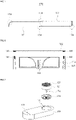
- FIGS. 2A, 2B, and 2C are views illustrating the state of use of the portable hood according to the embodiment of the present disclosure.
- the state of use of the portable hood illustrated in FIGS. 2A, 2B, and 2C illustrates the use of the portable hood in a kitchen to which a fixing hood 50 is fixed in a general household just as an induction cooker is fixed.
- the head unit 100 may be rotated such that the head unit 100 and the base unit 200 face each other so as to minimize space occupied by the base unit 200 and the head unit 100.
- the head unit 100 may be adjusted to be rotated to a left or right direction such that the sucking unit 110 of the head unit 100 is located above a cooking utensil 31 such as a pot.
- the sucking unit 110 may be adjusted to be located adjacently to the upper portion of the cooking utensil 31 according to a cooking environment such as the position of the burner being used, and thus oil vapor may be introduced to the sucking unit 110 at the position adjacent to the upper portion of the cooking utensil 31, so the efficiency of drawing oil vapor may be effectively increased.
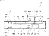
- FIG. 3 is a sectional view of the head unit 100 according to the embodiment of the present disclosure.
- the sectional view illustrated in FIG. 3 illustrates a section of the eccentric direction of the sucking unit 110 and the discharging unit 120.
- the sucking unit 110 may be open downward and may introduce air thereto from a position located under the sucking unit 110. Furthermore, the discharging unit 120 may be open upward and may discharge the air introduced through the sucking unit 110 in an upward direction.
- the sucking unit 110 may introduce oil vapor thereto from the lower side of the sucking unit 110 so as to improve the efficiency of drawing air. Furthermore, the introduced the oil vapor may be discharged in an upward direction through the discharging unit 120 located at a position eccentric from the sucking unit 110 in a horizontal direction, and as described above, the bypassing of air caused by air discharged through the discharging unit 120 or cooking heat of the cooking utensil 31 may be prevented.
- the discharging unit 120 may be configured to discharge oil vapor upward. Accordingly, as illustrated in FIGS. 2A, 2B, and 2C , the oil vapor may be discharged in a direction toward the fixing hood 50, whereby the portable hood may effectively remove oil vapor generated during cooking in cooperation with the fixing hood 50.
- the sucking unit 110 and the discharging unit 120 may be formed in the head unit 100 such that the sucking unit 110 and the discharging unit 120 are eccentrical so as not to overlap vertically. Accordingly, the flow of air introduced into the sucking unit 110 and the flow of air discharged from the discharging unit 120 may not affect each other, so the efficiency of drawing and discharging air may be improved.
- the drawing-force generation part 410 and 420 of the portable hood 10 may include a discharging fan 410.
- the discharging fan 410 may be installed in the discharging unit 120. Furthermore, the discharging fan 410 may generate drawing force such that air is introduced through the sucking unit 110 and discharged to the discharging unit 120.
- the discharging fan 410 may be installed at the discharging unit 12, whereby the center of weight of the portable hood 10 according to the embodiment of the present disclosure may be formed at the side of the columnar unit 300 at which the discharging unit 120 is formed. Accordingly, as illustrated in FIGS. 2A, 2B, and 2C , even if the sucking unit 110 of the head unit 100 rotates in a horizontal direction, the center of weight of the portable hood 10 may be located at the side of the columnar unit 300, so even when the head unit 100 rotates horizontally, the portable hood 10 according to the embodiment of the present disclosure may be prevented from tipping over.
- drawing-force generation part 410 and 420 may further include a fan motor 420.
- the fan motor 420 may be installed under the discharging fan 410 and may rotate the discharging fan 410.
- the discharging fan 410 and the fan motor 420 may be installed in the head unit 100 such that the discharging fan 410 and the fan motor 420 is located at the side of the columnar unit 300, preferably, at the upper side of the columnar unit 300 as illustrated in FIG. 3 , so as described above, the center of the entire weight of the portable hood may be formed at the columnar unit 300, whereby the tipping over of the portable hood 10 may be prevented.
- the fan motor 420, the discharging fan 410, and the columnar unit 300 are installed such that the central axes of the fan motor 420, the discharging fan 410, and the columnar unit 300 correspond to each other.
- the discharging fan 410 and the rotating shaft of the fan motor 420 are configured in vertical directions. Furthermore, the discharging fan 410 and the fan motor 420 may be installed in the head unit 100 such that the rotating shaft is located inside the columnar unit 300.
- the center of weight of the portable hood 10 may be formed to be adjacent to the columnar unit 300.
- FIG. 4 is a partial exploded perspective view of the portable hood 10 according to the embodiment of the present disclosure.
- FIG. 4 illustrates the disassembled state of a portion of the head unit 100 of the portable hood 10.
- the head unit 100 may include a head main body 130 and a flow-path portion 170.
- the sucking unit 110 and the discharging unit 120 described above may be formed at the head main body 130 according to the embodiment of the present disclosure such that the sucking unit 110 and the discharging unit 120 are eccentric in a horizontal direction.
- the flow-path portion 170 may be provided in the head main body 130 and may have a flow path of air through which air introduced through the sucking unit 110 flows to the discharging unit 120.
- FIG. 5 is a sectional view of the flow-path portion 170 taken along line B-B of FIG. 4 according to the embodiment of the present disclosure.
- the flow-path portion 170 may include a sucking inlet 171, a discharging outlet 172, and an inner flow path 173.
- the sucking inlet 171 may be formed by being open downward toward the sucking unit 110 of the head main body 130.
- the discharging outlet 172 may be formed by being open upward toward the discharging unit 120 of the head main body 130.
- the inner flow path 173 may communicate the sucking inlet with the discharging outlet 172 in a horizontal direction.
- the flow-path portion 170 as a container-shaped member having the sucking inlet 171, the discharging outlet 172, and the inner flow path 173 may be installed inside the head main body 130.
- the flow space 141 in which the flow-path portion 170 sits may be formed in the head main body 130 as illustrated in FIG. 4 .
- the flow-path portion 170 is provided as a separate member and is installed in the flow space 141 of the inside of the head main body 130, but the head main body 130 may have the sucking inlet, the discharging outlet 172, and the flow-path portion 170 having the inner flow path 173 formed inside the head main body 130 through the processing of the inside of the head main body 130.
- an edge portion 174 in which the flow direction of air is changed may be configured to have a round shape, so it is possible to minimize the flow loss of air generated when the air flowing through the flow-path portion 170 collides with the wall surface.
- a cross-sectional area of the discharging unit 120 may be formed wider than a cross-sectional area of the flow-path portion 170, in particular, a cross-sectional area of the inner flow path 173.
- flow loss may be caused by the expansion or contraction of a flow path. When a flow path expands or contracts, flow loss may be minimized in a case in which the cross-sectional area of the discharging unit 120 is wider than the cross-sectional area of the flow-path portion 170.
- the discharging fan 410 and the fan motor 420 may be installed in the head main body 130 such that the discharging fan 410 and the fan motor 420 are located at the upper side and lower side, respectively, of the discharging outlet 172 of the flow-path portion 170. More specifically, as illustrated in FIG. 3 , the discharging fan 410 may be installed in the head main body 130 such that the discharging fan 410 is located at the upper side of the discharging outlet 172 of the flow-path portion 170. Furthermore, the fan motor 420 may be installed in the head main body 130 such that the fan motor 420 is located at the lower side of the discharging outlet 172 of the flow-path portion 170.
- the fan motor 420 may not be required to be disassembled, so the process of the dissembling and washing of the portable hood may be simplified.
- the head main body 130 may include the casing main body 140, the upper casing 150, and the lower casing 160.
- the sucking inlet 171 may be formed in the sucking unit 110. Furthermore, as described above, a separate flow-path portion 170 may be installed in the casing main body 140. As illustrated in FIG. 3 , the flow space 141 in which the flow-path portion 170 sits may be formed in the casing main body 140.
- the discharging unit 120 may be formed at the upper casing 150 according to the embodiment of the present disclosure.
- the flow space 141 formed in the casing main body 140 may have a shape open upward, and the upper casing 150 may be coupled to the casing main body 140 from the upper side of the casing main body 140 to shield the flow space 141.
- a user may remove the flow-path portion 170 sitting in the flow space 141, so the washing of the flow-path portion 170 may be performed.
- the upper casing 150 may be coupled to the casing main body 140 such that the upper casing 150 covers the side surface of the casing main body 140. That is, the upper casing 150 may constitute the side outer surface of the head main body 130.
- the lower casing 160 according to the embodiment of the present disclosure may be coupled to the casing main body 140 from the lower side of the casing main body 140.
- the lower casing 160 according to the embodiment of the present disclosure may have a plate shape.
- a through hole (not shown) may be formed vertically through the lower casing 160 such that the through hole is located at a position corresponding to the sucking unit 110.
- the pre-filter 514 may be installed in the through hole formed in the lower casing 160.
- the pre-filter 514 may filter dust or foreign matter having a relatively large size introduced into the sucking unit 110.
- the discharging unit 120 may further include a fan housing 121.
- the fan housing 121 may protrude upward from the upper flat surface of the head main body 130.
- the upper casing 150 may constitute the upper flat surface of the head main body 130, and the fan housing 121 may be formed by protruding upward from the upper flat surface of the upper casing 150.
- the fan housing 121 may have a cylindrical shape open in a vertical direction, and the discharging fan 410 may be received in the fan housing 121. More specifically, in a state in which the fan housing 121 is configured to protrude upward from the upper casing 150 of the head main body 130, the fan housing 121 may be configured to receive the discharging fan 410 therein, whereby as illustrated in FIG. 3 , even if the discharging fan 410 and the fan motor 420 are arranged vertically in the head main body 130, the entire thickness of the head main body 130 may be slimmed.
- a discharge grill 122 may be removably coupled to an upper opening of the fan housing 121 according to the embodiment of the present disclosure and may cover the upper opening of the fan housing 121. Accordingly, the discharge grill 122 prevents accidents which may occur during the rotation of the discharging fan 410 and enables oil vapor to be discharged to the upper side of the discharging fan 410.
- the discharging fan 410 may be detachably coupled to the fan housing 121 by magnetic force.
- at least one first magnetic member M1 may be installed at an edge of the discharge grill 122, and a second magnetic member M2 corresponding to the first magnetic member M1 may be installed at the upper edge of the fan housing 121, whereby the discharge grill 122 may be removably coupled to the upper portion of the fan housing 121.
- both the first magnetic member M1 and the second magnetic member M2 may have magnetic force, but only one magnetic member may have magnetic force.
- the discharge grill 122 may be coupled to the fan housing 121 in a forcible fitting manner, or the discharge grill 122 may be hooked to the fan housing 121 by rotating the discharge grill 122. Accordingly, the discharge grill 122 may be detachably coupled to the fan housing 121 in various manners.
- the fan housing 121 is formed to be integrated with the upper casing 150 of the head main body 130, so the fan housing 121 is configured such that the fan housing 121 cannot be removed from the upper casing 150 of the head main body 130.
- the fan housing 121 may be detachably coupled to the upper casing 150 of the head main body 130.
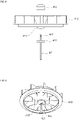
- FIGS. 8 and 9 are views illustrating a coupling structure between the discharging fan 410 and the fan motor 420 according to the embodiment of the present disclosure.
- the fan motor 420 may include a fan shaft 421.
- the fan shaft 421 may extend from the fan motor 420 toward the discharging fan 410 and may transmit the rotational force of the fan motor 420 to the discharging fan 410.
- threads 423 may be formed at the outer circumferential surface of an end part of the fan shaft 421 of the discharging fan 410.
- the discharging fan 410 may include a shaft through hole 411 (see FIG. 6 ) formed vertically therethrough.
- the end part of the fan shaft 421 may pass through the shaft through hole 411 such that the discharging fan 410 and the fan shaft 421 are coupled to each other.
- the end part of the fan shaft 421, that is, the end part on which the threads 423 are formed may be exposed to the upper side of the discharging fan 410.
- the discharging fan 410 may further include a fan nut 412.
- the fan nut 412 may be engaged with the threads formed at the end part of the fan shaft 421 passing through the shaft through hole 411 such that the discharging fan 410 is held to the fan shaft 421.
- the fan nut 412 may be unscrewed from the fan shaft 421, so the discharging fan 410 may be removed from the fan shaft 421.
- a fan holding part 413 may be formed at the lower part of the discharging fan 410. Furthermore, the fan shaft 421 may further include a shaft holding part 422 held in the fan holding part 413.
- the shaft holding part 422 may protrude radially outward from the outer surface of the fan shaft 421 and may be held in the fan holding part 413 when the fan shaft 421 passes through the shaft through hole 411.
- the shaft holding part 422 may be provided in the shape of a bar protruding radially outward from the fan shaft 421, and the fan holding part 413 may have a slot formed therein such that the bar-shaped shaft holding part 422 is inserted to the slot.
- the shaft holding part 422 held in the fan holding part 413 may rotate the discharging fan 410.
- FIGS. 10 , 11A, and 11B are views illustrating the height adjustment structure of the columnar unit 300 according to the embodiment of the present disclosure.
- the columnar unit 300 may include a first columnar member 310, a second columnar member 320, and a height adjustment unit 330.
- the first columnar member 310 may be coupled to the head unit 100 at a first side thereof.
- the first columnar member 310 is illustrated to have a cylindrical shape but may be provided in the shape of a polygonal pillar such as a container having a square cross section.
- the second columnar member 320 may be coupled to the base unit 200 at a first side thereof.
- the shape of the second columnar member 320 may correspond to the shape of the first columnar member 310 and may have a cylindrical shape in the embodiment of the present disclosure.
- the second columnar member 320 may have a shape different from the cylindrical shape by corresponding to the first columnar member 310.
- a second side of the second columnar member 320 that is, an upper area of the second columnar member 320 may be inserted through the lower portion of the first columnar member 310 which is a second side of the first columnar member 310. Accordingly, the height of the head unit 100 may be adjusted according to the height of the second columnar member 320 inserted into the lower portion of the first columnar member 310.
- the height adjustment unit 330 may vertically move the first columnar member 310 relative to the second columnar member 320 such that the height of the head unit 100 is adjusted.
- the height adjustment unit 330 may include a rack member 331, a pinion member 332, and a damper 333.
- the rack member 331 may be installed at a first side of one of the first columnar member 310 and the second columnar member 320. In the embodiment, as illustrated in FIGS. 11A and 11B , the rack member 331 is installed in the first columnar member 310.
- the rack member 331 is formed along the vertical direction of a first guide member 311 coupled to the inner surface of the first columnar member 310.
- the pinion member 332 may rotate in engagement with the rack member 331.
- the pinion member 332 may be coupled to the second columnar member 320 (or the first columnar member 310, the same hereinafter) through the damper 333, so the pinion member 332 may vertically move together with the second columnar member 320.
- the damper 333 may be installed at a second side of one of the first columnar member 310 and the second columnar member 320. That is, in a case in which the rack member 331 is installed at the first columnar member 310, the damper 333 may be installed at the second columnar member 320, and in a case in which the rack member 331 is installed at the second columnar member 320, the damper 333 may be installed at the first columnar member 310. In the embodiment of the present disclosure, the damper 333 is installed at the second columnar member 320. Furthermore, in the embodiment of the present disclosure, the damper 333 may be installed at a second guide member 321 coupled to the inner surface of the second columnar member 320.
- the damper 333 may be connected to the rotating shaft of the pinion member 332 and may vertically move the first columnar member 310 when the pinion member 332 rotates in engagement with the rack member 331.
- the damper 333 provides a load to the first columnar member 310 such that the vertical position of the first columnar member 310 is maintained, so the height of the head unit 100 may be adjusted to a predetermined height.
- a user may vertically move the head unit 100.
- the head unit 100 may vertically move while the rack member 331 operates in engagement with the pinion member 332.
- the vertical movement of the head unit 100 may stop at the desired height according to the load of the damper 333, so the height of the head unit 100 may be adjusted to the desired height.
- a guide groove 312 may be formed at the first guide member 311 along a vertical direction thereof. Furthermore, a guide rib (not shown) may be formed at the second guide member 321 such that the vertical movement of the head unit is guided with the guide rib inserted to the guide groove 312. Accordingly, the vertical relative movement of the first guide member 311 to the second guide member 321 may be stably guided, so the vertical movement of the first columnar member 310 may be stably performed.
- the head unit 100 rotates horizontally relative to the columnar unit 300.
- the portable hood 10 according to the embodiment of the present disclosure may further include a rotation unit 700 coupling the columnar unit 300 to the base unit 200 to each other such that the columnar unit 300 rotates relative to the base unit 200.
- FIGS. 12 and 13 are views illustrating the configuration of the rotation unit 700 according to the embodiment of the present disclosure.
- the rotation unit 700 may include a first rotating member 710 and a second rotating member 720.
- the first rotating member 710 may be installed at the lower portion of the columnar unit 300.
- the columnar unit 300 is composed of the first columnar member 310 and the second columnar member 320, and the first rotating member 710 is installed at the lower portion of the second columnar member 320.
- the second rotating member 720 may be installed at the base unit 200.
- the second rotating member 720 may support the first rotating member 710 such that the first rotating member 710 is rotatable so as to rotate the columnar unit 300.
- the first rotating member 710 has a shape of a circular plate. Furthermore, the second rotating member 720 may have a shape of a circular ring to support the first rotating member 710 such that the second rotating member 720 is rotatable along the inner circumference of the first rotating member 710. Accordingly, the first rotating member 710 may stably rotate in the second rotating member 720 having the shape of a circular ring.
- a holding protrusion 711 may be formed on the outer circumference of the first rotating member 710 by protruding outward in a radial direction therefrom. Furthermore, a plurality of holding recesses 721 may be formed at predetermined angle intervals at the inner circumference of the second rotating member 720.
- the holding protrusion 711 may be inserted and held in the holding recess 721 formed at a predetermined angle, a user may recognize a predetermined angular rotation and the holding of the holding protrusion 711 may be maintained at the associated angle in a state in which an external force is not applied.
- the three holding recesses 721 are formed at 90° intervals.
- the three holding recesses 721 may be formed at positions at which the base unit 200 and the head unit 100 are located side by side in a vertical direction, as illustrated in FIG. 2A , and at positions of the head unit 100 rotating 90° to the left and to the right relative to the base unit 200, as illustrated in FIGS. 2B and 2C .
- the holding recess 721 may be formed at an angle with a relatively high frequency of use among the rotation angles of the head unit 100 such that the use convenience of the portable hood 10 of the present disclosure is increased.
- the rotation unit 700 may further include a rotation control part 730.
- the rotation control part 730 may control the rotation of the first rotating member 710 such that the head unit 100 rotates only to a preset angle from a position parallel to the base unit 200.
- the rotation control part 730 may control the rotation of the first rotating member 710 such that the first rotating member 710 can rotate by 90° side to side to the maximum of 180°.
- the rotation control part 730 may include a control member 731 coupled to the first rotating member 710, and a control groove 732 formed at the base unit 200.
- the control groove 732 may be formed at the flat surface of the base unit 200 such that the control groove 732 has a semicircular shape of 180°.
- a control protrusion 731a formed at the control member 731 may be held in the control groove 732 such that the control member 731 rotates only within the range of 180° while the control member 731 rotates with the control protrusion 731a inserted in the control groove 732.
- the head unit 100 may be configured to rotate at 90° side to side, that is, only within the range of 180°, whereby the twisting of a cable connected from the base unit 200 to the head unit 100, for example, a power cable or signal cable for the rotation and control of the fan motor 420 may be minimized.
- the portable hood 10 may be used at various angles within a 180° rotation range and may cover any position at which the portable hood 10 is required to be used.
- the discharging fan 410 and the fan motor 420 of the portable hood 10 are described to be arranged vertically at the upper side of the columnar unit 300.
- the discharging fan 410 and the fan motor 420 according to the embodiment of the present disclosure may be provided to be integrated with each other and may be installed at the upper side of the columnar unit 300.
- FIGS. 14 to 16 are views illustrating the configuration of the discharging fan 410 and the fan motor 420 integrated with each other according to the embodiment of the present disclosure.
- the discharging fan 410 may be installed in the discharging unit 120, for example, inside the fan housing 121. Furthermore, the fan motor 420 may be installed in the discharging fan 410 and may rotate the discharging fan 410.
- the discharging unit 120 may further include a shaft connection member 123a.
- the shaft connection member 123a may connect the rotating shaft of the discharging fan 410 to the discharge grill 122 such that the discharging fan 410 rotates inside the fan housing 121.
- the discharging fan 410 and the fan motor 420 together may be removed from the fan housing 121 by the shaft connection member 123a.
- the discharging fan 410 and the fan motor 420 may be integrally received in the fan housing 121, and as described above, the center of weight of the portable hood 10 according to the embodiment of the present disclosure may be formed at the columnar unit 300, so the tipping over of the portable hood 10 may be prevented.
- the portable hood 10 may further include a first connector 127a and a second connector 128a.
- the first connector 127a may be installed at the discharge grill 122 and may be electrically connected to the fan motor 420. Furthermore, the second connector 128a may be installed at the fan housing 121 such that the second connector 128a is located at a position corresponding to the position of the first connector 127a.
- the second connector 128a may be connected to the first connector 127a and may supply power to the fan motor 420.
- the second connector 128a may be electrically connected to a printed circuit board installed at the base unit 200 through the columnar unit 300, so when the first connector 127a and the second connector 128a are connected to each other, power may be supplied to the fan motor 420.
- the discharging unit 120 may include a holding jaw 124a, a holding lever 125a and 125b, and an elastic member 126a.
- the holding jaw 124a may be installed at the discharge grill 122.
- the holding jaw 124a may be inserted into the fan housing 121 when the discharge grill 122 is mounted to the fan housing 121.
- the holding lever 125a and 125b may be installed at the fan housing 121 such that the holding lever 125a and 125b can be held in and released from the holding jaw 124a. Accordingly, in a state in which the holding lever 125a and 125b is held in the holding jaw 124a, the discharge grill 122 may be coupled to and held in the fan housing 121, and when the holding lever 125a and 125b is released from the holding jaw 124a, the discharge grill 122 may be removed from the fan housing 121.
- the elastic member 126a may elastically press the holding lever 125a and 125b in a direction in which the holding lever 125a and 125b are held in the holding jaw 124a.
- the holding lever 125a and 125b may be located at the outer side of the fan housing 121 and may be composed of a lever part 125a which a user can pull by the user's hand and a holding part 125b extending to the inner side of the fan housing 121 from the lever part 125a and being held in and released from the holding jaw 124a.
- the elastic member 126a may be provided as a tension spring and may pull the lever part 125a in a direction in which the holding part 125b is held in the holding jaw 124a such that the holding part 125b is maintained to be held in the holding jaw 124a.
- the base unit 200 may include a weight plate 220.
- the weight plate 220 according to the embodiment of the present disclosure may be made of metal and may be provided in the base unit 200 such that the columnar unit 300 and the head unit 100 are prevented from tipping over.
- the head unit 100 and the base unit 200 according to the embodiment of the present disclosure may be coupled eccentrically to the columnar unit 300 in horizontal directions, wherein the head unit 100 may be installed to be horizontally rotatable.
- the weight plate 220 made of relatively heavy metal may be provided in the base unit 200 and thus the center of weight of the portable hood may be located at a lower side of the portable hood, so the portable hood 10 according to the embodiment of the present disclosure may be prevented from tipping over.
- the portable hood 10 according to the embodiment of the present disclosure may further include a battery module 800.
- the portable hood 10 according to the embodiment of the present disclosure may be provided with a power cable (not shown) to receive power and may have the battery module 800 installed therein to increase portability such that the battery module 800 supplies actuating power required for operating the fan motor 420.
- the battery module 800 is provided inside the columnar unit 300. Accordingly, the important components are arranged in the columnar unit 300, and the center of weight of the portable hood may be formed at the columnar unit 300, so the tipping over of the portable hood 10 may be prevented.
- the battery module 800 is arranged at a lower portion of the inside of the columnar unit 300.
- the height adjustment unit 330 described above is installed in the columnar unit 300, as illustrated in FIG. 18B , the height adjustment unit 330 may be located at the upper side of the columnar unit 300, and the battery module 800 may be located at the lower portion of the columnar unit 300.
- the height adjustment of the columnar unit 300 may be performed, and due to the provision of the battery module 800 inside the columnar unit 300, the portable hood 10 according to the embodiment of the present disclosure may be more effectively prevented from tipping over.
- the battery module 800 may be installed to include a plurality of battery modules, as illustrated in FIG. 18A , the plurality of battery modules 800 may be horizontally arranged in parallel to each other in the columnar unit 300. Accordingly, the portable hood 10 according to the embodiment of the present disclosure may maintain a more stable standing state, so that the portable hood 10 may be prevented from tipping over.
- the width w1 of the base unit 200 in a direction crossing a direction toward the sucking unit 110 from the discharging unit 120 eccentric from each other may be equal to or wider than the width w2 of the head unit 100. That is, in the short length direction of the horizontal cross section of each of the base unit 200 and the head unit 100, the width w1 of the base unit 200 is equal to or wider than the width w2 of the head unit 100.
- the head unit 100 may be configured to rotate in a horizontal direction and may be configured to adjust height.
- the head unit 100 may be coupled to the columnar unit 300 such that the head unit 100 can adjust an angle in a vertical direction. Accordingly, the head unit 100 may perform the adjustment of air-introduction angle in addition to the height adjustment and may effectively respond even to a cooking utensil located at a height beyond the range of the height adjustment of the head unit 100.
- the portable hood 10 may further include a filter unit 500 as illustrated in FIG. 3 .
- the filter unit 500 may be installed in the sucking unit 110.
- the filter unit 500 may include at least one purification filter 512, 513, or 514 purifying air introduced into the sucking unit 110.
- the purification filter 512, 513, 514 may include at least one of a deodorization filter 512 and oil mist filter 513.
- the deodorization filter 512 and the oil mist filter 513 are installed in the sucking unit 110.
- the pre-filter 514 installed in the through hole of the lower casing 160 may be included in a component of the purification filter 512, 513, or 514.
- the oil mist filter 513 a fiber filter such as a non-woven fabric is applied. Furthermore, an aluminum mesh filter may be used as the pre-filter 514, and a filter made of corrugated activated carbon may be used as the deodorization filter 512.
- the example of each of the deodorization filter 512, the oil mist filter 513 and the pre-filter 514 described above is used in the embodiment of the preset disclosure, but filters made of other materials may be applied.
- the deodorization filter 512 may be inserted from the upper side of the sucking unit 110 of the casing main body 140 and may be installed in the sucking unit 110. Accordingly, after the upper casing 150 is removed from the casing main body 140, the replacement of the deodorization filter 512 may be performed.
- the oil mist filter 513 according to the embodiment of the present disclosure is provided as a roll filter.
- the portable hood 10 according to the embodiment of the present disclosure may include a roll filter unit 600 such that the oil mist filter 513 is discharged past the sucking unit 110 to the outside of the head unit 100.
- FIGS. 21 to 27 are views illustrating the configuration of the roll filter unit 600 according to the embodiment of the present disclosure.
- the roll filter unit 600 may include a filter roll 610 and the filter transportation unit 620.
- the oil mist filter 513 may be wound on the filter roll 610.
- the filter roll 610 may be rotatably installed at the head unit 100 with the oil mist filter 513 wound on the filter roll 610.
- the filter roll 610 is removably installed at the roll mounting part 142 formed at the lower portion of the casing main body 140 of the head main body 130.
- the roll mounting part 142 may include a roll receiving part 142a and a shaft coupling part 142b.
- the roll receiving part 142a may be open downward at a lower surface of the casing main body 140 such that the filter roll 610 may be inserted into the roll receiving part 142a from a lower side of the casing main body 140.
- the shaft coupling part 142b may be formed at each of the opposite inner wall surfaces of the roll receiving part 142a, so a roll coupling kit 612 to be described later of the filter roll 610 may be coupled to the shaft coupling part 142b.
- the filter roll 610 may include a filter drum 611 and the pair of roll coupling kits 612.
- the filter drum 611 may be provided to have a cylindrical shape, and the oil mist filter 513 may be wound on the filter drum 611 along an outer circumferential surface thereof.
- the pair of roll coupling kits 612 may be installed at the opposite sides of the filter drum 611, respectively.
- the pair of roll coupling kits 612 may support the filter drum 611 such that the filter drum 611 is rotatable, and when the filter roll 610 is installed in the roll mounting part 142, the filter roll 610 may be removably coupled to each of the shaft coupling parts 142b.
- the roll coupling kit 612 may include a kit body 613, a first shaft protrusion 614, and a second shaft protrusion 615.
- the first shaft protrusion 614 may be rotatably coupled to the side surface of the filter drum 611 by protruding from a first side surface of the kit body 613.
- the protrusion insertion hole 611a may be formed in the side surface of the filter drum 611 such that the first shaft protrusion 614 is rotatably inserted to the protrusion insertion hole 611a.
- the second shaft protrusion 615 may be inserted to the shaft coupling part 142b of the roll mounting part 142 by protruding from a second side surface of the kit body 613.
- the second shaft protrusion 615 when the second shaft protrusion 615 is coupled to the shaft coupling part 142b, the second shaft protrusion 615 may be pressed in a direction of the second shaft protrusion 615 inserted into the shaft coupling part 142b.
- the kit body 613 may include a first kit member 613a, a second kit member 613b, and a press member 613c.
- the second shaft protrusion 615 may be provided at the first kit member 613a according to the embodiment of the present disclosure and may be coupled to the first kit member 613a such that the second shaft protrusion 615 moves in a direction of the rotational axis of the filter drum 611.
- the first shaft protrusion 614 and the second shaft protrusion 615 may be formed to be integrated with flat surfaces of the opposite sides of the second kit member 613b, respectively.
- the press member 613c may be installed between the first kit member 613a and the second kit member 613b. Furthermore, the press member 613c may press the second kit member 613b in a direction in which the second shaft protrusion 615 is inserted into the shaft coupling part 142b. In the embodiment of the present disclosure, the press member 613c may be provided as a compression spring.
- a user when installing the filter roll 610 in the roll mounting part 142, a user may insert the filter roll 610 into the roll receiving part 142a.
- the user may push a second kit member 613b at a second side in a direction toward the first kit member 613a at the second side after inserting a second shaft protrusion 615 at a first side into the shaft coupling part 142b at the first side such that the second shaft protrusion 615 at the second side is inserted into the shaft coupling part 142b at the second side.
- the coupling force of the second shaft protrusion 615 to the shaft coupling part 142b and the coupling force of the first shaft protrusion 614 to the protrusion insertion hole 611a may be maintained constant by an elastic force of the press member 613c. Accordingly, when the filter transportation unit 620 moves the oil mist filter 513 wound on the filter roll 610, the filter transportation unit 620 may hold the oil mist filter 513 with tension and may prevent the oil mist filter 513 from being easily unwound.
- a cut part H may be formed by cutting a portion of an edge of the first kit member 613a directed toward the shaft coupling part 142b and may provide space into which a user can insert a finger to push the second kit member 613b.
- the filter transportation unit 620 may be installed in the head unit 100 such that the filter transportation unit 620 is located at a side opposite to the filter roll 610 with the sucking unit 110 placed between the filter transportation unit 620 and the filter roll 610.
- the filter roll 610 may be installed inside the casing main body 140 of the head main body 130.
- the filter roll 610 and the filter transportation unit 620 may be installed at the opposite sides, respectively, of the eccentric direction of the sucking unit 110 and the discharging unit 120.
- the filter roll 610 may be installed at a side of the discharging unit 120 and at a side opposite to the filter transportation unit 620.
- the filter transportation unit 620 may discharge the oil mist filter 513 extending past the sucking unit 110 from the filter roll 610 to the outside of the head unit 100.
- the filter transportation unit 620 may discharge the oil mist filter 513 to the upper side of the head unit 100.
- the filter transportation unit 620 may include a first roller unit 630 and a second roller unit 640.
- the first roller unit 630 and the second roller unit 640 may be installed in the casing main body 140 by being vertically spaced apart from each other and may discharge the oil mist filter 513 to the upper side of the head unit 100.
- the first roller unit 630 and the second roller unit 640 may include a first moving roller 631 and a second moving roller 632, and a first moving roller 641 and a second moving roller 642, respectively.
- the first moving rollers 631 and 641 and the second moving rollers 632 and 642 may rotate by facing each other in a horizontal direction with the oil mist filter 513 placed therebetween, so the oil mist filter 513 may be moved upward.
- corrugation having a shape of gear teeth may be formed on the outer circumferential surface of each of the first moving roller 631 or 641 and the second moving roller 632 or 642 such that the oil mist filter 513 is efficiently moved.
- the filter transportation unit 620 may further include a cutting unit 650.
- the cutting unit 650 may be located between the first roller unit 630 and the second roller unit 640 and may cut the purification filter 511, 512, 513, or 514 in a transverse direction.
- a new area of the oil mist filter 513 wound on the filter roll 610 may be moved to the sucking unit 110, and the area of the oil mist filter 513 used earlier may be moved to the outside of the head unit 100 along the filter transportation unit 620.
- maintaining the exposure of the end of the oil mist filter 513 to the upper side of the head unit 100 when using the oil mist filter 513 is provided as an example, and the oil mist filter 513 may be controlled to expose an end thereof to the upper side of the head unit 100 only when cutting the end of the oil mist filter 513.
- FIG. 25 is a view illustrating the configuration of the cutting unit 650 according to the embodiment of the present disclosure.
- the cutting unit 650 according to the embodiment of the present disclosure may include a cutter 651 cutting the oil mist filter 513.
- the cutting unit 650 according to the embodiment of the present disclosure may include a cutter moving unit 652 configured to transversely reciprocate the cutter 651 such that the oil mist filter 513 is transversely cut.
- the cutter moving unit 652 may include a belt 653 and a pair of pulleys 654.
- the cutter 651 installed at the belt 653 may transversely cut the oil mist filter 513 while reciprocating along the belt 653.
- the filter roll 610 may be installed in the roll mounting part 142 such that the oil mist filter 513 wound on the filter roll 610 is unwound at the lower part of the head main body 130 in a direction covering the lower part of the head main body 130 and extends toward the lower part of the sucking unit 110. Furthermore, the oil mist filter 513 moving past the sucking unit 110 may bend upward and may move to the upper side of the head unit 100 by the filter transportation unit 620. Through this configuration, the oil mist filter 513 unwound from the filter roll 610 may be moved by being bent only in one direction, so the efficient movement of the oil mist filter 513 by the filter transportation unit 620 may be performed.
- the upper casing 150 may include a filter discharging hole 151 formed vertically therethrough. Accordingly, the end of the oil mist filter 513 moved by the filter transportation unit 620 may be moved to the upper side of the head unit 100 through the filter discharging hole 151 formed in the upper casing 150 and may be discharged to the outside of the head unit 100.
- the filter discharging hole 151 may include an inclined surface 152.
- the inclined surface 152 may be formed on the inner wall surface of the filter discharging hole 151 by inclining toward the discharging unit 120 such that the oil mist filter 513 is discharged toward the discharging unit 120 when the oil mist filter 513 is discharged through the filter discharging hole 151.
- the oil mist filter 513 moved by being unwound from the filter roll 610 may be moved by being bent only in one direction and thus the efficient movement of the oil mist filter 513 may be performed. Additionally, when the oil mist filter 513 is discharged to the upper side of the head unit 100, the oil mist filter 513 may be discharged toward the discharging unit 120 located at a side opposite to a burner, so accidents due to the discharging of the oil mist filter 513 toward the burner may be prevented in advance.
- the casing main body 140 may include a first casing main body 140a and a second casing main body 140b.
- the first casing main body 140a may constitute a major part of the casing main body 140 according to the embodiment of the present disclosure.
- the sucking unit 110 and the roll mounting part 142 may be formed in the first casing main body 140a.
- the first casing main body 140a may include the flow space 141 formed therein to seat the flow-path portion 170 in the flow space 141 and may be coupled to the columnar unit 300.
- the second casing main body 140b may be coupled to the first casing main body 140a by a vertical hinge. Accordingly, as illustrated in FIG. 27 , the second casing main body 140b may open and close the first casing main body 140a in a horizontal direction.
- the filter transportation unit 620 installed in the casing main body 140 may be exposed to the outside as illustrated in FIG. 27 . Accordingly, after the second casing main body 140b is opened, the first roller unit 630 and the second roller unit 640 may be removed from the casing main body 140, so the first roller unit 630 and the second roller unit 640 used for a predetermined period of time may be washed.
- the first moving roller 631 of the first roller unit 630 and the first moving roller 641 of the second roller unit 640 are installed in the first casing main body 140a. Furthermore, the second moving roller 632 of the first roller unit 630 and the second moving roller 642 of the second roller unit 640 are installed in the second casing main body 140b.
- the oil mist filter 513 may be fitted between the first moving roller 631 or 641 and the second moving roller 632 or 642, so the replacement of the filter roll 610 may be further efficiently performed.
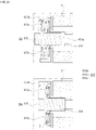
- FIGS. 28A, 28B, 28C, 28D , 29A, 29B, and 29C are views illustrating a process in which the filter roll 610 is newly mounted in the portable hood 10 according to the embodiment of the present disclosure.
- FIGS. 28A, 28B, 28C, 28D , 29A, 29B, and 29C show only reference numerals necessary for description so that the configurations of the illustrated drawings can be more clearly identified.
- FIGS. 28A, 28B, 28C, 28D , 29A, 29B, and 29C as illustrated in FIG. 28A , in a state in which the portable hood 10 according to the embodiment of the present disclosure is assembled, first, the upper casing 150 and the lower casing 160 may be removed from the casing main body 140 as illustrated in FIG. 28B .
- the front of the first casing main body 140a is opened by rotating the second casing main body 140b relative to the first casing main body 140a.
- the first moving roller 631 or 641 is installed in the first casing main body 140a
- the second moving roller 632 or 642 is installed in the first casing main body 140a.
- the filter roll 610 may be mounted to the roll mounting part 142 formed at the lower surface of the first casing main body 140a according to the method described above.
- the oil mist filter 513 may be unwound by pulling the end of the oil mist filter 513 from the filter roll 610 mounted to the roll mounting part 142 and may be bent at the front end of the first casing main body 140a, and as illustrated in FIG. 29B , the oil mist filter 513 may be directed upward.
- a flat surface of a side of the oil mist filter 513 may be in close contact with the front of the first moving roller 631 or 641 installed in the first casing main body 140a.
- the oil mist filter 513 may be located between the first moving roller 631 or 641 and the second moving roller 632 or 642 and may be held therebetween, with the end of the oil mist filter 513 exposed to the upper side of the casing main body 140.
- the installation of the oil mist filter 513 may be completed by exposing the end of the oil mist filter 513 to the upper side of the head unit 100.
- the coupling of the upper casing 150 to the casing main body 140 is performed after passing the end of the oil mist filter 513 through the filter discharging hole 151.
- the lower casing 160 may first be coupled to the first casing main body 140a and then the second casing main body 140b may be rotated.
- the filter unit 500 installed at the sucking unit 110 includes the deodorization filter 512, the oil mist filter 513, and the pre-filter 514, which are made of a non-woven fabric, corrugated activated carbon, and aluminum mesh, respectively. This is because the portable hood 10 according to the above-described embodiment is suitable for removing oil vapor generated during cooking.
- the portable hood 10 may be configured to function as an air purifier.
- the deodorization filter 512 may be replaced through the sucking inlet 171 of the casing main body 140, and the oil mist filter 513 may be replaced through the replacement of the filter roll 610.
- the pre-filter 514 may be detachably installed at the lower casing 160.
- a user may replace the deodorization filter 512, the oil mist filter 513, or the pre-filter 514 according to the embodiment described above with a filter suitable for air purification to be used, so the scope of use of the portable hood 10 according to the embodiment of the present disclosure may expand.
- the pre-filter 514 may be replaced with a plastic mesh filter suitable for the air purifier.
- a HEPA filter and a deodorization filter may be installed sequentially at a position at which the deodorization filter 512 described above is installed.
- a user may use the portable hood as the air purifier with the oil mist filter 513 unremoved or removed.
Landscapes
- Engineering & Computer Science (AREA)
- Mechanical Engineering (AREA)
- General Engineering & Computer Science (AREA)
- Chemical & Material Sciences (AREA)
- Combustion & Propulsion (AREA)
- Ventilation (AREA)
- Structures Of Non-Positive Displacement Pumps (AREA)
Applications Claiming Priority (1)
| Application Number | Priority Date | Filing Date | Title |
|---|---|---|---|
| KR1020210054478A KR20220147387A (ko) | 2021-04-27 | 2021-04-27 | 포터블 후드 |
Publications (2)
| Publication Number | Publication Date |
|---|---|
| EP4083516A1 true EP4083516A1 (fr) | 2022-11-02 |
| EP4083516B1 EP4083516B1 (fr) | 2026-04-29 |
Family
ID=80034856
Family Applications (1)
| Application Number | Title | Priority Date | Filing Date |
|---|---|---|---|
| EP22153079.3A Active EP4083516B1 (fr) | 2021-04-27 | 2022-01-25 | Hotte portative |
Country Status (4)
| Country | Link |
|---|---|
| US (1) | US12247746B2 (fr) |
| EP (1) | EP4083516B1 (fr) |
| KR (1) | KR20220147387A (fr) |
| WO (1) | WO2022231089A1 (fr) |
Families Citing this family (4)
| Publication number | Priority date | Publication date | Assignee | Title |
|---|---|---|---|---|
| WO2022191397A1 (fr) * | 2021-03-08 | 2022-09-15 | 엘지전자 주식회사 | Appareil portatif d'écoulement d'air et procédé de commande associé |
| KR20220147387A (ko) | 2021-04-27 | 2022-11-03 | 엘지전자 주식회사 | 포터블 후드 |
| KR20220157703A (ko) * | 2021-05-21 | 2022-11-29 | 엘지전자 주식회사 | 포터블 후드 |
| KR20240097560A (ko) * | 2022-12-20 | 2024-06-27 | 삼성전자주식회사 | 휴대용 후드 및 그 제어 방법 |
Citations (5)
| Publication number | Priority date | Publication date | Assignee | Title |
|---|---|---|---|---|
| JPS4897490U (fr) * | 1972-02-24 | 1973-11-19 | ||
| JPS6217737U (fr) * | 1985-07-17 | 1987-02-02 | ||
| DE102004055947A1 (de) * | 2004-11-19 | 2006-07-20 | BSH Bosch und Siemens Hausgeräte GmbH | Dunstabzugshaube mit Einzelstellenbesaugung |
| KR20180099393A (ko) * | 2017-02-28 | 2018-09-05 | 엘지전자 주식회사 | 포터블 후드 |
| KR20210022253A (ko) * | 2019-08-20 | 2021-03-03 | 설철환 | 연기정화장치 |
Family Cites Families (46)
| Publication number | Priority date | Publication date | Assignee | Title |
|---|---|---|---|---|
| US2253127A (en) | 1938-10-12 | 1941-08-19 | Westinghouse Electric & Mfg Co | Oscillating fan |
| FR1513243A (fr) * | 1966-05-09 | 1968-02-16 | Micro-capteur mobile pour fumées et vapeurs | |
| JPS4897490A (fr) | 1972-10-11 | 1973-12-12 | ||
| US3886560A (en) | 1974-05-31 | 1975-05-27 | Tandy Corp | Antenna swivel mount |
| DE3503236A1 (de) | 1985-01-31 | 1986-08-07 | Licentia Patent-Verwaltungs-Gmbh, 6000 Frankfurt | Kuecheneinrichtung mit einer horizontalen kochplatte |
| JPS6217737A (ja) | 1985-07-17 | 1987-01-26 | Nec Corp | 光ヘテロダイン検波装置 |
| US5603562A (en) | 1995-02-13 | 1997-02-18 | Huang; Thomas M. | Combination fan/lamp |
| FR2761620B1 (fr) | 1997-04-02 | 1999-05-28 | Sarl Geom | Hotte aspirante de table |
| US7380759B1 (en) | 1998-11-16 | 2008-06-03 | Garmin Corporation | Multi-position articulating mounting apparatus for an electronic device |
| US6402822B1 (en) | 2000-02-15 | 2002-06-11 | Hmi Industries, Inc. | Furnace filter system |
| US6497738B2 (en) * | 2001-01-10 | 2002-12-24 | Yu-Yuan Lin | Filter for indoor barbecue |
| JP2002286268A (ja) * | 2001-03-28 | 2002-10-03 | Fuji Industrial Co Ltd | レンジフード |
| US6843834B2 (en) | 2003-01-06 | 2005-01-18 | Jerry H. Schumacher | Self-renewing air filter |
| KR200321802Y1 (ko) | 2003-05-02 | 2003-07-31 | 유팔남 | 로스터용 흡/배기장치 |
| KR200394656Y1 (ko) | 2005-06-24 | 2005-09-02 | 배수호 | 휴대용 집진장치 |
| DE102005055029A1 (de) | 2005-11-18 | 2007-05-24 | Max Homeier | Dunstabzugshaube |
| US7785382B2 (en) | 2006-02-23 | 2010-08-31 | Illinois Tool Works Inc | Exhaust hood with grease absorbing material on a roll |
| US7507151B1 (en) * | 2006-05-12 | 2009-03-24 | University Of Central Florida Research Foundation, Inc. | High efficiency solar powered fan |
| KR100819482B1 (ko) | 2006-09-29 | 2008-04-07 | 이동일 | 주방용 후드장치 |
| CN202109563U (zh) | 2011-06-23 | 2012-01-11 | 韩亚林 | 家用煎烤便携排烟机 |
| US9624944B2 (en) | 2011-11-28 | 2017-04-18 | Sunbeam Products, Inc. | Bladeless fan |
| KR20160104514A (ko) | 2015-02-26 | 2016-09-05 | 이창주 | 이동식 렌지 후드 |
| US10337528B2 (en) | 2015-03-23 | 2019-07-02 | Anthony Rivera | Detachable fan systems |
| DE202015106627U1 (de) | 2015-12-04 | 2016-01-11 | Riadh Jraied | Mobile Entlüftungsvorrichtung |
| KR102480324B1 (ko) | 2016-03-09 | 2022-12-23 | 엘지전자 주식회사 | 공기정화기 |
| DE202016002873U1 (de) | 2016-05-08 | 2016-07-13 | Florian Hermsen | Bewegbare, freistehende Dunstabzugshaube |
| KR102462768B1 (ko) | 2016-06-03 | 2022-11-02 | 엘지전자 주식회사 | 후드의 동작 방법, 그리고 이러한 후드를 포함하는 조리기기 시스템의 동작 방법 |
| KR20180058047A (ko) | 2016-11-23 | 2018-05-31 | 코웨이 주식회사 | 휴대용 후드 장치 |
| KR20180099392A (ko) | 2017-02-28 | 2018-09-05 | 엘지전자 주식회사 | 포터블 후드 |
| KR101961013B1 (ko) * | 2017-04-26 | 2019-03-21 | 엘지전자 주식회사 | 다운드래프트 방식의 공기정화장치 및 이를 포함하는 조리시스템 |
| KR200487625Y1 (ko) * | 2017-08-04 | 2018-12-05 | 조정욱 | 휴대용 흡기장치 |
| KR102590135B1 (ko) | 2017-11-16 | 2023-10-18 | 삼성전자주식회사 | 필터 모듈 및 이를 갖춘 공기청정기 |
| KR102051551B1 (ko) * | 2017-12-04 | 2019-12-03 | 이두영 | 조리용기를 위한 휴대용 연기정화장치 |
| EP3502572B1 (fr) | 2017-12-19 | 2021-02-24 | BSH Hausgeräte GmbH | Dispositif d'évacuation de fumée, appareil de cuisine pourvu de plaque de cuisson et dispositif d'évacuation de fumée et procédé de fonctionnement d'un dispositif d'évacuation de fumée |
| KR102062667B1 (ko) | 2018-01-17 | 2020-02-11 | 엘지전자 주식회사 | 공기청정기 및 그 제어방법 |
| CN108397808A (zh) | 2018-05-30 | 2018-08-14 | 杭州富阳腾飞科技有限公司 | 一种便携式吸油烟机 |
| KR101962730B1 (ko) | 2018-11-08 | 2019-03-28 | (주)한빛엔지니어링건축사사무소 | 필터 교체가 용이한 공동주택 주방후드 거름망 |
| CN110360631A (zh) | 2019-07-19 | 2019-10-22 | 中山市欧博尔电器有限公司 | 一种便携移动式油烟机 |
| US11654389B2 (en) | 2019-10-28 | 2023-05-23 | Lg Electronics Inc. | Air cleaner with cutter |
| WO2022030767A1 (fr) | 2020-08-06 | 2022-02-10 | 엘지전자 주식회사 | Purificateur d'air et son procédé de commande |
| KR102868820B1 (ko) | 2020-08-06 | 2025-10-02 | 엘지전자 주식회사 | 롤러장치 및 이를 사용하는 공기정화기 |
| CN112283774A (zh) | 2020-10-26 | 2021-01-29 | 李军廷 | 便携式抽油烟装置、系统和作业方法 |
| CN112555922A (zh) | 2020-11-13 | 2021-03-26 | 浙江意米特电器有限公司 | 一种便携式无烟灶台 |
| WO2022191397A1 (fr) | 2021-03-08 | 2022-09-15 | 엘지전자 주식회사 | Appareil portatif d'écoulement d'air et procédé de commande associé |
| KR20220147387A (ko) | 2021-04-27 | 2022-11-03 | 엘지전자 주식회사 | 포터블 후드 |
| KR20220157703A (ko) | 2021-05-21 | 2022-11-29 | 엘지전자 주식회사 | 포터블 후드 |
-
2021
- 2021-04-27 KR KR1020210054478A patent/KR20220147387A/ko active Pending
- 2021-12-17 WO PCT/KR2021/019328 patent/WO2022231089A1/fr not_active Ceased
-
2022
- 2022-01-21 US US17/580,751 patent/US12247746B2/en active Active
- 2022-01-25 EP EP22153079.3A patent/EP4083516B1/fr active Active
Patent Citations (5)
| Publication number | Priority date | Publication date | Assignee | Title |
|---|---|---|---|---|
| JPS4897490U (fr) * | 1972-02-24 | 1973-11-19 | ||
| JPS6217737U (fr) * | 1985-07-17 | 1987-02-02 | ||
| DE102004055947A1 (de) * | 2004-11-19 | 2006-07-20 | BSH Bosch und Siemens Hausgeräte GmbH | Dunstabzugshaube mit Einzelstellenbesaugung |
| KR20180099393A (ko) * | 2017-02-28 | 2018-09-05 | 엘지전자 주식회사 | 포터블 후드 |
| KR20210022253A (ko) * | 2019-08-20 | 2021-03-03 | 설철환 | 연기정화장치 |
Also Published As
| Publication number | Publication date |
|---|---|
| KR20220147387A (ko) | 2022-11-03 |
| US12247746B2 (en) | 2025-03-11 |
| WO2022231089A1 (fr) | 2022-11-03 |
| US20220341598A1 (en) | 2022-10-27 |
| EP4083516B1 (fr) | 2026-04-29 |
Similar Documents
| Publication | Publication Date | Title |
|---|---|---|
| EP4083516A1 (fr) | Hotte portative | |
| EP4092332A1 (fr) | Hotte portative | |
| EP3208562B1 (fr) | Purificateur d'air destiné à un réfrigérateur | |
| KR101191873B1 (ko) | 가정용 조리기구 커버 및 조리방법 | |
| CN217423376U (zh) | 集成灶 | |
| CN112273986A (zh) | 一种炒菜机 | |
| JP2019528420A (ja) | 料理用レンジ台 | |
| CN114076327B (zh) | 空气净化装置和吸油烟机 | |
| US11819159B2 (en) | Electric grill with a filtration system for filtering the fumes released from food cooking | |
| CN217118187U (zh) | 一种新型无烟煎烤器 | |
| CN214791361U (zh) | 集烟罩组件及吸油烟机 | |
| CN219460924U (zh) | 一种下出风的模块化空气炸锅 | |
| CN209944432U (zh) | 家用电器 | |
| CN110755947A (zh) | 油烟净化装置 | |
| CN112690669B (zh) | 一种多功能料理的集成实现方法 | |
| CN209944433U (zh) | 家用电器 | |
| CN214341677U (zh) | 一种炒菜机 | |
| KR20220147388A (ko) | 이동형 공기 유동 장치 | |
| CN110500627B (zh) | 旋转滤网、滤网组件及吸油烟机 | |
| CN209944434U (zh) | 厨房电器 | |
| CN209944435U (zh) | 家用电器 | |
| CN114135902A (zh) | 一种方便高温消毒柜和烤箱更换的多功能集成灶 | |
| JP3246757U (ja) | 卓上排油煙機 | |
| CN215570640U (zh) | 一种双头嵌入式电磁炉 | |
| CN111102623A (zh) | 一种抽油烟机 |
Legal Events
| Date | Code | Title | Description |
|---|---|---|---|
| PUAI | Public reference made under article 153(3) epc to a published international application that has entered the european phase |
Free format text: ORIGINAL CODE: 0009012 |
|
| STAA | Information on the status of an ep patent application or granted ep patent |
Free format text: STATUS: REQUEST FOR EXAMINATION WAS MADE |
|
| 17P | Request for examination filed |
Effective date: 20220224 |
|
| AK | Designated contracting states |
Kind code of ref document: A1 Designated state(s): AL AT BE BG CH CY CZ DE DK EE ES FI FR GB GR HR HU IE IS IT LI LT LU LV MC MK MT NL NO PL PT RO RS SE SI SK SM TR |
|
| STAA | Information on the status of an ep patent application or granted ep patent |
Free format text: STATUS: EXAMINATION IS IN PROGRESS |
|
| 17Q | First examination report despatched |
Effective date: 20240212 |
|
| RAP3 | Party data changed (applicant data changed or rights of an application transferred) |
Owner name: LG ELECTRONICS INC. |
|
| RIN1 | Information on inventor provided before grant (corrected) |
Inventor name: LEE, TAEYUN Inventor name: JO, YU NA Inventor name: LEE, DEUKWON Inventor name: LEE, SANG YOON Inventor name: OH, MIN KYU |
|
| GRAP | Despatch of communication of intention to grant a patent |
Free format text: ORIGINAL CODE: EPIDOSNIGR1 |
|
| STAA | Information on the status of an ep patent application or granted ep patent |
Free format text: STATUS: GRANT OF PATENT IS INTENDED |
|
| INTG | Intention to grant announced |
Effective date: 20251128 |
|
| GRAS | Grant fee paid |
Free format text: ORIGINAL CODE: EPIDOSNIGR3 |
|
| GRAA | (expected) grant |
Free format text: ORIGINAL CODE: 0009210 |
|
| STAA | Information on the status of an ep patent application or granted ep patent |
Free format text: STATUS: THE PATENT HAS BEEN GRANTED |