EP4083533A1 - Raccord fluidique entre deux conduits regulateur de debit - Google Patents
Raccord fluidique entre deux conduits regulateur de debit Download PDFInfo
- Publication number
- EP4083533A1 EP4083533A1 EP22169144.7A EP22169144A EP4083533A1 EP 4083533 A1 EP4083533 A1 EP 4083533A1 EP 22169144 A EP22169144 A EP 22169144A EP 4083533 A1 EP4083533 A1 EP 4083533A1
- Authority
- EP
- European Patent Office
- Prior art keywords
- fluid
- collar
- connector
- conduit
- projections
- Prior art date
- Legal status (The legal status is an assumption and is not a legal conclusion. Google has not performed a legal analysis and makes no representation as to the accuracy of the status listed.)
- Pending
Links
- 239000012530 fluid Substances 0.000 title claims abstract description 32
- 238000004378 air conditioning Methods 0.000 claims abstract description 10
- 230000008878 coupling Effects 0.000 claims abstract description 9
- 238000010168 coupling process Methods 0.000 claims abstract description 9
- 238000005859 coupling reaction Methods 0.000 claims abstract description 9
- 239000013013 elastic material Substances 0.000 claims abstract description 5
- 229920001971 elastomer Polymers 0.000 claims description 3
- 239000000806 elastomer Substances 0.000 claims description 3
- 230000009467 reduction Effects 0.000 description 4
- 230000006978 adaptation Effects 0.000 description 3
- 230000008859 change Effects 0.000 description 2
- 239000000463 material Substances 0.000 description 2
- 230000001105 regulatory effect Effects 0.000 description 2
- 238000004026 adhesive bonding Methods 0.000 description 1
- 230000001276 controlling effect Effects 0.000 description 1
- 238000009432 framing Methods 0.000 description 1
- 230000007246 mechanism Effects 0.000 description 1
- 238000003466 welding Methods 0.000 description 1
Images


Classifications
-
- F—MECHANICAL ENGINEERING; LIGHTING; HEATING; WEAPONS; BLASTING
- F24—HEATING; RANGES; VENTILATING
- F24F—AIR-CONDITIONING; AIR-HUMIDIFICATION; VENTILATION; USE OF AIR CURRENTS FOR SCREENING
- F24F13/00—Details common to, or for air-conditioning, air-humidification, ventilation or use of air currents for screening
- F24F13/02—Ducting arrangements
- F24F13/0209—Ducting arrangements characterised by their connecting means, e.g. flanges
-
- F—MECHANICAL ENGINEERING; LIGHTING; HEATING; WEAPONS; BLASTING
- F16—ENGINEERING ELEMENTS AND UNITS; GENERAL MEASURES FOR PRODUCING AND MAINTAINING EFFECTIVE FUNCTIONING OF MACHINES OR INSTALLATIONS; THERMAL INSULATION IN GENERAL
- F16L—PIPES; JOINTS OR FITTINGS FOR PIPES; SUPPORTS FOR PIPES, CABLES OR PROTECTIVE TUBING; MEANS FOR THERMAL INSULATION IN GENERAL
- F16L29/00—Joints with fluid cut-off means
-
- F—MECHANICAL ENGINEERING; LIGHTING; HEATING; WEAPONS; BLASTING
- F16—ENGINEERING ELEMENTS AND UNITS; GENERAL MEASURES FOR PRODUCING AND MAINTAINING EFFECTIVE FUNCTIONING OF MACHINES OR INSTALLATIONS; THERMAL INSULATION IN GENERAL
- F16K—VALVES; TAPS; COCKS; ACTUATING-FLOATS; DEVICES FOR VENTING OR AERATING
- F16K7/00—Diaphragm valves or cut-off apparatus, e.g. with a member deformed, but not moved bodily, to close the passage ; Pinch valves
- F16K7/02—Diaphragm valves or cut-off apparatus, e.g. with a member deformed, but not moved bodily, to close the passage ; Pinch valves with tubular diaphragm
- F16K7/04—Diaphragm valves or cut-off apparatus, e.g. with a member deformed, but not moved bodily, to close the passage ; Pinch valves with tubular diaphragm constrictable by external radial force
- F16K7/06—Diaphragm valves or cut-off apparatus, e.g. with a member deformed, but not moved bodily, to close the passage ; Pinch valves with tubular diaphragm constrictable by external radial force by means of a screw-spindle, cam, or other mechanical means
-
- F—MECHANICAL ENGINEERING; LIGHTING; HEATING; WEAPONS; BLASTING
- F16—ENGINEERING ELEMENTS AND UNITS; GENERAL MEASURES FOR PRODUCING AND MAINTAINING EFFECTIVE FUNCTIONING OF MACHINES OR INSTALLATIONS; THERMAL INSULATION IN GENERAL
- F16L—PIPES; JOINTS OR FITTINGS FOR PIPES; SUPPORTS FOR PIPES, CABLES OR PROTECTIVE TUBING; MEANS FOR THERMAL INSULATION IN GENERAL
- F16L21/00—Joints with sleeve or socket
- F16L21/002—Sleeves or nipples for pipes of the same diameter; Reduction pieces
- F16L21/005—Sleeves or nipples for pipes of the same diameter; Reduction pieces made of elastic material, e.g. partly or completely surrounded by clamping devices
-
- F—MECHANICAL ENGINEERING; LIGHTING; HEATING; WEAPONS; BLASTING
- F16—ENGINEERING ELEMENTS AND UNITS; GENERAL MEASURES FOR PRODUCING AND MAINTAINING EFFECTIVE FUNCTIONING OF MACHINES OR INSTALLATIONS; THERMAL INSULATION IN GENERAL
- F16L—PIPES; JOINTS OR FITTINGS FOR PIPES; SUPPORTS FOR PIPES, CABLES OR PROTECTIVE TUBING; MEANS FOR THERMAL INSULATION IN GENERAL
- F16L27/00—Adjustable joints; Joints allowing movement
- F16L27/10—Adjustable joints; Joints allowing movement comprising a flexible connection only
- F16L27/107—Adjustable joints; Joints allowing movement comprising a flexible connection only the ends of the pipe being interconnected by a flexible sleeve
-
- F—MECHANICAL ENGINEERING; LIGHTING; HEATING; WEAPONS; BLASTING
- F16—ENGINEERING ELEMENTS AND UNITS; GENERAL MEASURES FOR PRODUCING AND MAINTAINING EFFECTIVE FUNCTIONING OF MACHINES OR INSTALLATIONS; THERMAL INSULATION IN GENERAL
- F16L—PIPES; JOINTS OR FITTINGS FOR PIPES; SUPPORTS FOR PIPES, CABLES OR PROTECTIVE TUBING; MEANS FOR THERMAL INSULATION IN GENERAL
- F16L55/00—Devices or appurtenances for use in, or in connection with, pipes or pipe systems
- F16L55/02—Energy absorbers; Noise absorbers
- F16L55/027—Throttle passages
-
- F—MECHANICAL ENGINEERING; LIGHTING; HEATING; WEAPONS; BLASTING
- F24—HEATING; RANGES; VENTILATING
- F24F—AIR-CONDITIONING; AIR-HUMIDIFICATION; VENTILATION; USE OF AIR CURRENTS FOR SCREENING
- F24F13/00—Details common to, or for air-conditioning, air-humidification, ventilation or use of air currents for screening
- F24F13/08—Air-flow control members, e.g. louvres, grilles, flaps or guide plates
-
- B—PERFORMING OPERATIONS; TRANSPORTING
- B64—AIRCRAFT; AVIATION; COSMONAUTICS
- B64D—EQUIPMENT FOR FITTING IN OR TO AIRCRAFT; FLIGHT SUITS; PARACHUTES; ARRANGEMENT OR MOUNTING OF POWER PLANTS OR PROPULSION TRANSMISSIONS IN AIRCRAFT
- B64D13/00—Arrangements or adaptations of air-treatment apparatus for aircraft crew or passengers, or freight space
-
- F—MECHANICAL ENGINEERING; LIGHTING; HEATING; WEAPONS; BLASTING
- F16—ENGINEERING ELEMENTS AND UNITS; GENERAL MEASURES FOR PRODUCING AND MAINTAINING EFFECTIVE FUNCTIONING OF MACHINES OR INSTALLATIONS; THERMAL INSULATION IN GENERAL
- F16K—VALVES; TAPS; COCKS; ACTUATING-FLOATS; DEVICES FOR VENTING OR AERATING
- F16K7/00—Diaphragm valves or cut-off apparatus, e.g. with a member deformed, but not moved bodily, to close the passage ; Pinch valves
- F16K7/02—Diaphragm valves or cut-off apparatus, e.g. with a member deformed, but not moved bodily, to close the passage ; Pinch valves with tubular diaphragm
- F16K7/04—Diaphragm valves or cut-off apparatus, e.g. with a member deformed, but not moved bodily, to close the passage ; Pinch valves with tubular diaphragm constrictable by external radial force
- F16K7/06—Diaphragm valves or cut-off apparatus, e.g. with a member deformed, but not moved bodily, to close the passage ; Pinch valves with tubular diaphragm constrictable by external radial force by means of a screw-spindle, cam, or other mechanical means
- F16K7/061—Screw clamps
Definitions
- the present invention relates to flow control systems for controlling flow in fluid conduits of a system such as an air conditioning system.
- many pipes carry fluids whose flow must be regulated.
- the aircraft is equipped with an air conditioning system.
- the air circulates in the pipes to supply the cabin or the cockpit.
- the distribution of the flow of certain pipes must be adapted according to the configuration of the cabin of the aircraft chosen by an airline.
- the pipes are then fitted with devices for modifying the flow rate. In general, they are fixed inside said pipes and when the flow must be modified, it is necessary to dismantle the pipe to change the regulating device.
- the present invention aims to propose a fluid connection making it possible to regulate the flow and to modify the regulation without having to dismantle or change the pipes.
- the present invention relates to a fluidic connector intended to connect two conduits characterized in that it consists of at least one elastic material and in that it comprises a conduit of polylobed shape surrounded by an adjustable clamp allowing by tightening it to deform it so as to reduce the interior space of the conduit and to adapt the flow rate of the flow circulating in the fitting when it is associated with the conduits.
- the tightening of the collar makes it possible to easily and quickly regulate the flow of the fluid circulating in the ducts.
- the invention provides at least one of the following optional characteristics, taken individually or in combination.
- the fitting is made of elastomer.
- the collar includes markings to estimate the tightening achieved.
- the markings include visible lines on the flange of the collar.
- the coupling comprises two projections towards the exterior of the latter on either side of the pipe forming a shoulder.
- the protrusions are formed by widening and then shrinking the perimeter of the pipe forming a connection.
- the duct is ring-shaped polylobed between the projections.
- the projections form a bellows in order to facilitate the radial retraction of the part of the duct interposed between them.
- the present invention also relates to a fluidic assembly comprising two conduits and a connector having one or more of the preceding characteristics, characterized in that each end of the said connector is connected to one of the ends of each of the conduits, the tightening of the collar making it possible to regulate the flow rate of the fluid circulating in the conduits.
- the present invention also relates to an air conditioning system comprising such a fluid assembly.
- the present invention also relates to an aircraft provided with such an air conditioning system.
- the present invention relates to a fluid assembly 2 represented on the figure 1 comprising two conduits 4, 6 interconnected by means of a fluid connection 8.
- the fluid assembly 2 is part of a more global system in which a fluid circulates and the flow rate of which needs to be adapted.
- the air conditioning system of an aircraft as seen above requires numerous pipes to circulate the air in the cabin or the cockpit provided with a regulation device.
- Each end 8A, 8B of the fluid connection 8 is fixed to one end 5 (the other end is not visible because covered by the connection) free of the conduit 4, 6 respectively by any type of known means and for example by the intermediate a clamp, by screwing, welding, gluing or other.
- the conduits 4, 6 and the fluid connector 8 have the same cross-sectional shape at the connection between them with slightly different diameters to allow their assembly, one thus being able to be inserted inside on the other: the ends of conduits 4 and 6 are inserted inside conduit 9 and fixed to the fitting using a clamp not shown.
- the fluid connection 8 is in the form of a cylindrical pipe 9 like the pipes 4 and 6 but any other more complex shape is possible; the conduits 4, 6 and the fluid connection 8 have a circular section but any other cross-sectional shape is possible such as elliptical, ovoid or other.
- the longitudinal direction is the direction of the central axis X of the duct forming the connector 8, or at least at its ends 8A and 8B.
- a transverse plane is a plane perpendicular to this axis.
- the fluid connection 8 is elastic: it consists of at least one elastic material.
- the conduit 9 of the connector is belted, surrounded by an adjustable clamping collar 12 allowing by tightening it, as shown in the picture 3 by the arrows, to deform it by reducing the interior space (or more precisely the volume thereof) and by the same by reducing the passage window for the fluid.
- the clamp 12 is a different component from the fixing means, namely in the illustrated example of the clamps used to secure the fitting to the ducts; it may be of the same shape as said fixing means, namely in the form of a clamp. On at least part or even all of the duct 9, depending on the tightening, the section of the duct (or more precisely the area thereof) in a transverse plane is reduced.
- the diameter of the collar is smaller and the internal area of any section of the deformed conduit of the coupling in a transverse plane is reduced. In this way, it is possible to adapt the flow rate circulating in the connector 8 and therefore in the ducts 4, 6 associated with the connector.
- the material is chosen to be elastic so as to resume its initial shape when the collar 12 is loosened.
- the collar 12 is installed in a central position of the connector, namely here equidistant from the ends 8A, 8B.
- the fitting is made of one or more elastic materials.
- the connector is made of a single material, the elastomer.
- the collar 12 comprises marking signs 14 making it possible to define the reduction in the passage section and to have an indicator function.
- the collar is in the form of a flange 16, for example made of rectangular plastic, the ends of which are linked by a clamping device 18 of the rack or other type.
- a clamping device 18 of the Serflex (registered trademark) type with a screw 20.
- the clamping device causes the clamp to be clamped.
- Collar 12 is self-locking, ie when you stop actuating screw 20, the collar remains locked in position (or in a close position depending on the mechanism used in the clamping device).
- the marking is made in the form of visible lines 22.
- Lines 22 are parallel to each other and transverse to the longitudinal direction of the flange. In the form shown, they are a different color from the flange. In the illustrated form, the chosen color is very distinctive of the gray color of the flange, namely, for example, red in color to improve the visibility of the lines.
- the lines 22 are distributed homogeneously, namely at equidistance from one another, but they could not be according to another embodiment. They make it possible to evaluate the tightening obtained according to the number of remaining visible lines. Other types of marking can be used only either as a replacement for the lines or in combination with them, such as shapes in relief, for example.
- the connector 8 comprises two projections 24, 26, in relief relative to the outer surface of the connector and towards the outside of the latter and over its entire periphery transversely or at least a part thereof, on both sides.
- the projections 24, 26 form a shoulder for the collar 12. They can be in a continuous or discontinuous form.
- the projections 24, 26 can be arranged at a distance from it as shown in the figures and not adjoin it; in the form shown, they are closer to the ends 8A, 8B than to the collar 12, but any other configuration is possible, such as being equidistant or closer to the collar 12 than to the ends 8A, 8B.
- the projections 24, 26 are formed by a gradual enlargement and then a reduction of the perimeter of the conduit of the connector 8, which gives each projection a semi-annular shape forming a bellows; the curves formed in section by a central longitudinal plane at the connection respectively by the widening and the reduction of the perimeter of the connection are symmetrical with respect to the transverse plane crossing the connection at the level of the largest perimeter of the projection.
- the projections 24 and 26 have an identical shape.
- the protrusions also have the function of facilitating the radial retraction of the part of the duct 9 interposed between them: when the collar 12 is tightened, the protrusions by deforming avoid generating too much tension at the level of the skin, the envelope of the fitting.
- the duct 9 in the undeformed state between the projections 24 and 26 is in the form of a polylobed annular cylindrical duct, namely having at least two lobes and more precisely here quadrilobed.
- the duct has a succession of protruding parts separated by recesses.
- the protruding parts can have any type of shape and for example a cross section with a rounded outline like an arc of a circle or as on the figure 4 a semi-rectangular cross-section with rounded corners. This shape allows the duct to retract from more homogeneous way.
- the section of the duct 9 is circular apart from the polylobed annular part located between the projections 24 and 26 and the projections 24, 26 are formed by an enlargement and then a reduction in the diameter of the duct forming a connection, which induces an enlargement and a decrease in scope.
- each end 8A, 8B of said connector is connected to one of the ends of each of the ducts 4 , 6.
- the picture 2 shows the connection 8 in the undeformed state, namely with an untightened collar.
- the collar is placed between the ends connected to the conduits 4, 6. It is also placed between the conduits.
- Five lines 22 are visible.
- the collar 12 is then tightened until the desired flow rate level is reached. This level can be read directly on the flange 16 through the marking 14. On the picture 3 , more than two lines are visible. The tightening of the collar makes it possible to easily and quickly adapt the flow rate of the fluid circulating in the ducts.
- the conduit 9 being elastic, by loosening the collar, the connection resumes its initial shape and can therefore take all possible forms for a different flow rate adaptation, whether it is necessary to tighten or loosen the collar.
- the level of adaptation of the flow rate can be modified as many times as desired according to the configuration of the required system and this without having to remove or modify a part of the overall system and without compromising the tightness in the coupling of the ducts between them or with the connection.
Landscapes
- Engineering & Computer Science (AREA)
- General Engineering & Computer Science (AREA)
- Mechanical Engineering (AREA)
- Chemical & Material Sciences (AREA)
- Combustion & Propulsion (AREA)
- Quick-Acting Or Multi-Walled Pipe Joints (AREA)
- Duct Arrangements (AREA)
- Pipe Accessories (AREA)
Abstract
L'invention a pour objet un raccord fluidique destiné à connecter deux conduits (4, 6) d'un système tel qu'un système de conditionnement d'air. Le raccord (8) est constitué d'au moins un matériau élastique et comprend un conduit (9) entouré par un collier de serrage (12) réglable permettant en le serrant de le déformer de manière à réduire l'espace intérieur du conduit. Le serrage du collier (12) permet de réguler facilement et rapidement le débit du fluide circulant dans les conduits (4, 6).
Description
- La présente invention concerne les systèmes de régulation de débit permettant de réguler un flux dans des conduits de fluide d'un système tel qu'un système de conditionnement d'air.
- Dans un aéronef, de nombreuses canalisations conduisent des fluides dont le débit doit être régulé. Ainsi par exemple l'aéronef est équipé d'un système de conditionnement d'air. L'air circule dans les canalisations pour alimenter la cabine ou le cockpit. La distribution du débit de certaines canalisations doit être adaptée en fonction de la configuration de la cabine de l'aéronef choisie par une compagnie aérienne. Les canalisations sont alors munies de dispositifs de modification du débit. En général, ils sont fixés à l'intérieur desdites canalisations et lorsque le débit doit être modifié, il est nécessaire de démonter la canalisation pour changer le dispositif de régulation.
- La présente invention vise à proposer un raccord fluidique permettant de réguler le débit et de modifier la régulation sans avoir à démonter ou changer les canalisations.
- A cet effet, la présente invention concerne un raccord fluidique destiné à connecter deux conduits caractérisé en ce qu'il est constitué d'au moins un matériau élastique et en ce qu'il comprend un conduit de forme polylobée entouré par un collier de serrage réglable permettant en le serrant de le déformer de manière à réduire l'espace intérieur du conduit et à adapter le débit du flux circulant dans le raccord lorsqu'il est associé aux conduits.
- Le serrage du collier permet de réguler facilement et rapidement le débit du fluide circulant dans les conduits.
- L'invention prévoit au moins l'une des caractéristiques optionnelles suivantes, prises isolément ou en combinaison.
- Le raccord est constitué d'élastomère.
- Le collier comprend des marquages permettant d'estimer le serrage atteint.
- Les marquages comprennent des traits visibles sur la bride du collier.
- Le raccord comprend deux saillies vers l'extérieur de celui-ci de part et d'autre du conduit formant épaulement.
- Les saillies sont formées par un élargissement puis une diminution du périmètre du conduit formant raccord.
- Le conduit est de forme annulaire polylobé entre les saillies.
- Les saillies forment soufflet afin de faciliter la rétractation radiale de la partie du conduit intercalée entre elles.
- La présente invention concerne également un ensemble fluidique comprenant deux conduits et un raccord présentant une ou plusieurs des caractéristiques précédentes, caractérisé en ce que chaque extrémité dudit raccord est connectée à l'une des extrémités de chacun des conduits, le serrage du collier permettant de réguler le débit du fluide circulant dans les conduits.
- La présente invention concerne également un système de conditionnement d'air comprenant un tel ensemble fluidique.
- La présente invention concerne également un aéronef pourvu d'un tel système de conditionnement d'air.
- D'autres buts, caractéristiques et avantages ressortiront de la description de l'invention qui va suivre, description donnée à titre d'exemple uniquement non limitatif, en référence aux dessins ci-annexés dans lesquels :
- [
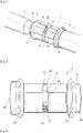
Fig. 1 ] est une vue en perspective d'un ensemble fluidique comprenant un raccord et deux conduits selon la présente invention ; - [
Fig. 2 ] est une vue en perspective de côté du raccord selon lafigure 1 à l'état non déformé ; - [
Fig. 3 ] est une vue en perspective de côté du raccord selon lafigure 2 à l'état déformé ; - [
Fig. 4 ] est une vue en perspective selon un autre angle du raccord selon lafigure 2 . - La présente invention se rapporte à un ensemble fluidique 2 représenté sur la
figure 1 comprenant deux conduits 4, 6 raccordés entre eux par l'intermédiaire d'un raccord 8 fluidique. L'ensemble fluidique 2 fait partie d'un système plus global dans lequel un fluide circule et dont le débit nécessite d'être adapté. A titre illustratif, le système de conditionnement d'air d'un aéronef comme vu plus haut requiert de nombreuses canalisations pour faire circuler l'air dans la cabine ou le cockpit pourvues de dispositif de régulation. Chaque extrémité 8A, 8B du raccord 8 fluidique est fixée à une extrémité 5 (l'autre extrémité n'est pas visible car recouverte par le raccord) libre du conduit respectivement 4, 6 par tout type de moyen connu et par exemple par l'intermédiaire d'un collier de serrage, par vissage, soudage, collage ou autre. Dans la forme illustrée, les conduits 4, 6 et le raccord fluidique 8 présentent la même forme de section au niveau de la connexion entre eux avec des diamètres légèrement différents pour permettre leur assemblage, l'un pouvant ainsi s'insérer à l'intérieur de l'autre : les extrémités des conduits 4 et 6 sont insérées à l'intérieur du conduit 9 et fixés au raccord à l'aide d'un collier de serrage non illustré. Dans la forme de réalisation illustrée sur lesfigures 1 à 4 , le raccord fluidique 8 se présente sous la forme d'un conduit 9 cylindrique comme les conduits 4 et 6 mais toute autre forme plus complexe est possible ; les conduits 4, 6 et le raccord 8 fluidique présentent une section circulaire mais toute autre forme de section est possible telle que elliptique, ovoïde ou autre. La direction longitudinale est la direction de l'axe X central du conduit formant le raccord 8, ou au moins au niveau de ses extrémités 8A et 8B. Un plan transversal est un plan perpendiculaire à cet axe. - Le raccord fluidique 8 est élastique : il est constitué d'au moins un matériau élastique. Le conduit 9 du raccord est ceinturé, entouré par un collier 12 de serrage réglable permettant en le serrant, comme montré sur la
figure 3 par les flèches, de le déformer en en réduisant l'espace intérieur (ou plus précisément le volume de celui-ci) et par la même en réduisant la fenêtre de passage pour le fluide. Le collier 12 de serrage est un composant différent des moyens de fixation à savoir dans l'exemple illustré des colliers de serrage utilisés pour fixer le raccord aux conduits ; il peut être de la même forme que lesdits moyens de fixation à savoir sous la forme d'un collier de serrage. Sur au moins une partie voire l'ensemble du conduit 9, suivant le serrage, la section du conduit (ou plus précisément l'aire de celle-ci) dans un plan transversal est réduite. Sur lafigure 3 en comparaison avec lafigure 2 , le diamètre du collier est plus faible et l'aire intérieure de toute section du conduit déformé du raccord dans un plan transversal est réduite. De cette manière, il est possible d'adapter le débit du flux circulant dans le raccord 8 et donc dans les conduits 4, 6 associés au raccord. Le matériau est choisi élastique de manière à reprendre sa forme initiale lorsque le collier 12 est desserré. Dans la forme illustrée, le collier 12 est installé dans une position centrale du raccord à savoir ici à équidistance des extrémités 8A, 8B. Le raccord est fait d'un ou plusieurs matériaux élastiques. Dans une forme de réalisation possible, le raccord est constitué d'un seul matériau, l'élastomère. - Comme montré sur les
figures 1 à 4 , le collier 12 comprend des signes de marquage 14 permettant de définir la réduction de la section de passage et d'avoir une fonction d'indicateur. Selon la forme de réalisation illustrée, le collier se présente sous la forme d'une bride 16 par exemple en plastique rectangulaire dont les extrémités sont liées par un dispositif 18 de serrage de type à crémaillère ou autre. Dans la forme illustrée, il s'agit d'un dispositif 18 de serrage de type Serflex (marque déposée) à vis 20. Lorsque l'on tourne la vis 20, le dispositif de serrage provoque le serrage du collier. Le collier 12 est autobloquant à savoir que lorsque l'on arrête d'actionner la vis 20, le collier reste bloqué en position (ou dans une position proche suivant le mécanisme utilisé dans le dispositif de serrage). Dans la forme de réalisation illustrée, le marquage est réalisé sous la forme de traits 22 visibles. Les traits 22 sont parallèles entre eux et transversaux par rapport à la direction longitudinale de la bride. Dans la forme illustrée, ils sont de couleur différente de la bride. Dans la forme illustrée, la couleur choisie est bien distinctive de la couleur grise de la bride à savoir par exemple de couleur rouge pour améliorer la visibilité des traits. Les traits 22 sont répartis de manière homogène à savoir à équidistance l'un de l'autre mais ils pourraient ne pas l'être selon une autre forme de réalisation. Ils permettent d'évaluer suivant le nombre de traits visibles restants le serrage obtenu. D'autres types de marquage peuvent être utilisés que ce soit en remplacement des traits ou en combinaison avec ceux-ci comme par exemple des formes en relief. - Le raccord 8 comprend deux saillies 24, 26, en relief par rapport à la surface extérieure du raccord et vers l'extérieur de celui-ci et sur toute sa périphérie transversalement ou au moins une partie de celle-ci, de part et d'autre d'un espace autour duquel le collier 12 est mis en place : les saillies 24, 26 forment épaulement pour le collier 12. Elles peuvent se présenter sous une forme continue ou discontinue. Ces saillies 24, 26 maintiennent ainsi en place le collier dans la direction longitudinale du raccord. Elles empêchent le collier 12 de se déplacer longitudinalement en l'encadrant de part et d'autre. Lorsque le collier 12 est en place, les saillies 24, 26 peuvent être disposées à distance de celui-ci comme montré sur les figures et ne pas le jouxter ; dans la forme illustrée, elles sont plus proches des extrémités 8A, 8B que du collier 12 mais toute autre configuration est possible comme d'être à équidistance ou d'être plus proches du collier 12 que des extrémités 8A, 8B. Dans la forme de réalisation illustrée, les saillies 24, 26 sont formées par un élargissement puis une diminution, progressifs du périmètre du conduit du raccord 8 ce qui donne à chaque saillie une forme semi-annulaire formant soufflet ; les courbes formées en section par un plan longitudinal central au raccord respectivement par l'élargissement et la diminution du périmètre du raccord sont symétriques par rapport au plan transversal traversant le raccord au niveau du périmètre le plus grand de la saillie. Les saillies 24 et 26 ont une forme identique. Les saillies ont aussi pour fonction de faciliter la rétractation radiale de la partie du conduit 9 intercalée entre elles : lorsque le collier 12 est serré, les saillies en se déformant évitent de générer une trop forte tension au niveau de la peau, de l'enveloppe du raccord.
- Dans la forme illustrée sur les
figures 1 et 2 , le conduit 9 à l'état non déformé entre les saillies 24 et 26 se présente sous la forme d'un conduit cylindrique annulaire polylobé, à savoir présentant au moins deux lobes et plus précisément ici quadrilobé. Le conduit présente une succession de parties en saillie séparées par des creux. Les parties en saillie peuvent présentés tout type de forme et par exemple une section transversale au contour arrondi comme un arc de cercle ou comme sur lafigure 4 une section transversale semi rectangulaire dont les coins sont arrondis. Cette forme permet au conduit de se rétracter de manière plus homogène. Dans la forme de réalisation illustrée sur lesfigures 1 à 4 , la section du conduit 9 est circulaire en dehors de la partie annulaire polylobée se trouvant entre les saillies 24 et 26 et les saillies 24, 26 sont formées par un élargissement puis une diminution du diamètre du conduit formant raccord ce qui induit un élargissement et une diminution du périmètre. - Lorsque les conduits 4, 6 d'un système sont mis en place, comme ceux d'un système de conditionnement d'air dans un aéronef, chaque extrémité 8A, 8B dudit raccord est connectée à l'une des extrémités de chacun des conduits 4, 6. La
figure 2 montre le raccord 8 à l'état non déformé à savoir avec un collier non serré. Le collier se trouve placé entre les extrémités connectées aux conduits 4, 6. Il est également placé entre les conduits. Cinq traits 22 sont visibles. Comme montré sur lafigure 3 , le collier 12 est alors serré jusqu'à ce que le niveau de débit du flux souhaité soit atteint. Ce niveau peut être lu directement sur la bride 16 au travers du marquage 14. Sur lafigure 3 , plus que deux traits sont visibles. Le serrage du collier permet d'adapter facilement et rapidement le débit du fluide circulant dans les conduits. Le conduit 9 étant élastique, en desserrant le collier, le raccord reprend sa forme initiale et peut donc prendre toutes les formes possibles pour une adaptation de débit différente, qu'il soit nécessaire de serrer ou desserrer le collier. Le niveau d'adaptation du débit peut être modifié autant de fois que souhaité selon la configuration du système requis et ceci sans avoir à retirer ou modifier une pièce du système global et sans compromettre l'étanchéité dans le couplage des conduits entre eux ou avec le raccord. - Il n'est donc plus nécessaire d'installer un dispositif d'adaptation du débit à l'intérieur des conduits de l'ensemble fluidique. Il n'est plus nécessaire non plus d'avoir à dimensionner les conduits. Il est facile et rapide de reconfigurer le système de conditionnement d'air ou tout système comprenant un tel ensemble fluidique.
Claims (11)
- Raccord fluidique destiné à connecter deux conduits (4, 6) caractérisé en ce qu'il est constitué d'au moins un matériau élastique et en ce qu'il comprend un conduit (9) de forme polylobée entouré par un collier de serrage (12) réglable permettant en le serrant de le déformer de manière à réduire l'espace intérieur du conduit et à adapter le débit du flux circulant dans le raccord lorsqu'il est connecté aux conduits.
- Raccord fluidique selon la revendication 1, caractérisé en ce qu'il est constitué d'élastomère.
- Raccord fluidique selon l'une des revendications 1 ou 2, caractérisé en ce que le collier (12) comprend des marquages permettant d'estimer le serrage atteint.
- Raccord fluidique selon la revendication 3, caractérisé en ce que les marquages comprennent des traits (22) visibles sur la bride du collier (12).
- Raccord fluidique selon l'une des revendications 1 à 4, caractérisé en ce qu'il comprend deux saillies (24, 26) vers l'extérieur de celui-ci de part et d'autre du conduit (9) formant épaulement.
- Raccord fluidique selon la revendication 5, caractérisé en ce que les saillies (24, 26) sont formées par un élargissement puis une diminution du périmètre du conduit formant raccord (8).
- Raccord fluidique selon l'une des revendications 5 ou 6, caractérisé en ce que le conduit (9) est de forme annulaire polylobé entre les saillies (24, 26).
- Raccord fluidique selon l'une des revendications 5 à 7, caractérisé en ce que les saillies forment soufflet afin de faciliter la rétractation radiale de la partie du conduit (9) intercalée entre elles.
- Ensemble fluidique comprenant deux conduits et un raccord selon l'une des revendications 1 à 8, caractérisé en ce que chaque extrémité (8A, 8B) dudit raccord est connectée à l'une des extrémités (5, autre extrémité non visible) de chacun des conduits, le serrage du collier permettant de réguler le débit du fluide circulant dans les conduits.
- Système de conditionnement d'air comprenant un ensemble fluidique selon la revendication 9.
- Aéronef comprenant un système de conditionnement d'air selon la revendication 10.
Applications Claiming Priority (1)
| Application Number | Priority Date | Filing Date | Title |
|---|---|---|---|
| FR2104391A FR3122473B1 (fr) | 2021-04-28 | 2021-04-28 | Raccord fluidique entre deux conduits regulateur de debit |
Publications (1)
| Publication Number | Publication Date |
|---|---|
| EP4083533A1 true EP4083533A1 (fr) | 2022-11-02 |
Family
ID=76034879
Family Applications (1)
| Application Number | Title | Priority Date | Filing Date |
|---|---|---|---|
| EP22169144.7A Pending EP4083533A1 (fr) | 2021-04-28 | 2022-04-21 | Raccord fluidique entre deux conduits regulateur de debit |
Country Status (4)
| Country | Link |
|---|---|
| US (1) | US11841093B2 (fr) |
| EP (1) | EP4083533A1 (fr) |
| CN (1) | CN115247730A (fr) |
| FR (1) | FR3122473B1 (fr) |
Citations (8)
| Publication number | Priority date | Publication date | Assignee | Title |
|---|---|---|---|---|
| US2212733A (en) * | 1937-12-09 | 1940-08-27 | Gail G Grigsby | Valve |
| FR1321347A (fr) * | 1962-05-08 | 1963-03-15 | Anthes Imp Company Ltd | Raccord pour tuyaux, notamment pour tuyaux en fonte |
| US3508587A (en) * | 1966-09-29 | 1970-04-28 | Hans A Mauch | Tubular structural member |
| JPH0363452A (ja) * | 1989-07-31 | 1991-03-19 | Fujita Corp | 空気調和設備の風量調節装置 |
| JP2004293782A (ja) * | 2003-03-07 | 2004-10-21 | Mitsuboshi Co Ltd | 異形チューブおよびそれを用いた流体装置 |
| WO2015103675A1 (fr) * | 2014-01-12 | 2015-07-16 | Gilbertson Darren | Systèmes et procédés pour gaines de ventilation |
| WO2017003937A1 (fr) * | 2015-06-29 | 2017-01-05 | Kci Licensing, Inc. | Appareil pour l'irrigation à pression négative |
| US20180363817A1 (en) * | 2017-06-14 | 2018-12-20 | Systemair Mfg. Inc. | Vibration dampening ventilation coupler |
Family Cites Families (31)
| Publication number | Priority date | Publication date | Assignee | Title |
|---|---|---|---|---|
| US820216A (en) * | 1905-03-31 | 1906-05-08 | Everett K Leffingwell | Tube-compressor. |
| US1024876A (en) * | 1910-11-21 | 1912-04-30 | James A Barbour | Valve. |
| US2195993A (en) * | 1938-12-23 | 1940-04-02 | Gen Electric | Flexible coupling |
| US2792942A (en) * | 1953-04-14 | 1957-05-21 | Feuillet Georges | Portable apparatus for the purifying and filtering of water |
| FR1260370A (fr) * | 1960-06-18 | 1961-05-05 | Compteur pour fluides | |
| US3120230A (en) * | 1960-10-24 | 1964-02-04 | Jack H Sanders | Surgical clamp |
| US3204919A (en) * | 1961-07-31 | 1965-09-07 | Tripoli | Split sleeve control valve |
| US3166819A (en) * | 1961-09-07 | 1965-01-26 | Carl B Robbins | Clip for embalming operations |
| US3254869A (en) * | 1962-04-11 | 1966-06-07 | Kenneth W Easey | Valving device for a flexible pleated conduit |
| US3162921A (en) * | 1963-04-09 | 1964-12-29 | Sterling Automotive Mfg Compan | Adjustable clamp |
| US3584830A (en) * | 1968-10-18 | 1971-06-15 | Wilbur R Koehn | Clamp for resilient tubing |
| US3556157A (en) * | 1968-11-22 | 1971-01-19 | Corning Glass Works | Linear fluid restrictor having a variable coefficient of restriction and method for making the same |
| US3613661A (en) * | 1968-12-20 | 1971-10-19 | Nayan S Shah | Mechanically controlling flow through living body ducts |
| US4018060A (en) * | 1975-08-29 | 1977-04-19 | The Garrett Corporation | Air conditioning system for aircraft |
| US3982722A (en) * | 1975-11-21 | 1976-09-28 | General Motors Corporation | Magnetic control valve |
| US4293031A (en) * | 1977-12-01 | 1981-10-06 | Wynn Oil Company | Engine cooling system flushing apparatus and method |
| US5395349A (en) * | 1991-12-13 | 1995-03-07 | Endovascular Technologies, Inc. | Dual valve reinforced sheath and method |
| US5873813A (en) * | 1998-02-05 | 1999-02-23 | B.S.W. Partnership | Method and apparatus for producing and maintaining a penile erection |
| DE60211942T2 (de) * | 2001-12-04 | 2007-01-25 | Cook Inc., Bloomington | Zugangs ventil |
| US20050092944A1 (en) * | 2003-02-04 | 2005-05-05 | Patterson Mark A. | Throttle valve apparatus for controlling fluid flow |
| CN100593089C (zh) * | 2005-04-06 | 2010-03-03 | 塞姆瓦克股份有限公司 | 柔性阀 |
| US7255322B1 (en) * | 2006-04-21 | 2007-08-14 | John Tiwet | Pinch valve system with extended life |
| EP2664544B1 (fr) * | 2012-03-21 | 2018-05-23 | Airbus Operations GmbH | Procédé pour commander un système de climatisation d'avion et système de climatisation d'avion |
| CN202914838U (zh) * | 2012-07-13 | 2013-05-01 | 丹佛斯(天津)有限公司 | 流量控制装置 |
| CN203876536U (zh) * | 2013-01-07 | 2014-10-15 | 佛吉亚内饰系统印度私营责任有限公司 | 用于导向和控制由hvac系统排出的气流的改良通风装置 |
| US9451730B2 (en) * | 2013-03-06 | 2016-09-20 | Amazon Technologies, Inc. | Managing airflow supplied through soft ducts |
| CN203256282U (zh) * | 2013-04-19 | 2013-10-30 | 西安森凯节能环保科技有限公司 | 一种高炉喷煤流量调节分配气力输送装置 |
| DE112014007021T5 (de) * | 2014-10-01 | 2017-07-13 | Faurecia Interior Systems India Pvt. Ltd. | Entlüftungsvorrichtung, umfassend eine flexible Leitung zur Regelung der Luftmenge |
| EP3444508A1 (fr) * | 2017-08-17 | 2019-02-20 | Sartorius Stedim Biotech GmbH | Robinet-vanne à manchon déformable |
| US11519435B2 (en) * | 2019-07-16 | 2022-12-06 | Goodrich Corporation | Valve for aircraft inflation system |
| US11427891B2 (en) * | 2019-07-24 | 2022-08-30 | Nibco Inc. | Low silicon copper alloy piping components and articles |
-
2021
- 2021-04-28 FR FR2104391A patent/FR3122473B1/fr active Active
-
2022
- 2022-04-21 EP EP22169144.7A patent/EP4083533A1/fr active Pending
- 2022-04-26 CN CN202210444892.9A patent/CN115247730A/zh active Pending
- 2022-04-27 US US17/730,746 patent/US11841093B2/en active Active
Patent Citations (8)
| Publication number | Priority date | Publication date | Assignee | Title |
|---|---|---|---|---|
| US2212733A (en) * | 1937-12-09 | 1940-08-27 | Gail G Grigsby | Valve |
| FR1321347A (fr) * | 1962-05-08 | 1963-03-15 | Anthes Imp Company Ltd | Raccord pour tuyaux, notamment pour tuyaux en fonte |
| US3508587A (en) * | 1966-09-29 | 1970-04-28 | Hans A Mauch | Tubular structural member |
| JPH0363452A (ja) * | 1989-07-31 | 1991-03-19 | Fujita Corp | 空気調和設備の風量調節装置 |
| JP2004293782A (ja) * | 2003-03-07 | 2004-10-21 | Mitsuboshi Co Ltd | 異形チューブおよびそれを用いた流体装置 |
| WO2015103675A1 (fr) * | 2014-01-12 | 2015-07-16 | Gilbertson Darren | Systèmes et procédés pour gaines de ventilation |
| WO2017003937A1 (fr) * | 2015-06-29 | 2017-01-05 | Kci Licensing, Inc. | Appareil pour l'irrigation à pression négative |
| US20180363817A1 (en) * | 2017-06-14 | 2018-12-20 | Systemair Mfg. Inc. | Vibration dampening ventilation coupler |
Also Published As
| Publication number | Publication date |
|---|---|
| FR3122473B1 (fr) | 2023-05-26 |
| US11841093B2 (en) | 2023-12-12 |
| US20220349504A1 (en) | 2022-11-03 |
| FR3122473A1 (fr) | 2022-11-04 |
| CN115247730A (zh) | 2022-10-28 |
Similar Documents
| Publication | Publication Date | Title |
|---|---|---|
| EP0340122B1 (fr) | Dispositif d'assemblage rapide d'éléments de raccordement pour des structures, ossatures, supports et autres assemblages | |
| EP0481871B1 (fr) | Bride pour le raccordement des tubulures d'entrée et de sortie d'un évaporateur | |
| EP1039195B1 (fr) | Collier de fixation pour pièce tubulaire | |
| FR2711761A1 (fr) | Dispositif de raccordement rapide. | |
| ES2247816T3 (es) | Acoplamiento de tuberia. | |
| FR3004233A1 (fr) | Dispositif pour la fixation, sur une paroi, d'un raccord de canalisation | |
| EP4083533A1 (fr) | Raccord fluidique entre deux conduits regulateur de debit | |
| FR2708096A1 (fr) | Dispositif de fixation d'éléments de blindage. | |
| EP2613990B1 (fr) | Système de purge | |
| EP3965242B1 (fr) | Rampe à géométrie variable pour harnais électrique et aéronef comportant au moins une telle rampe | |
| EP1090245A1 (fr) | Procede de montage d'un raccord a l'extremite d'un tube et nouveau type de raccord permettant sa mise en oeuvre | |
| FR2777968A1 (fr) | Dispositifde fixation d'un tube sur un support,en particulier dans un vehicule automobilie | |
| WO2002021033A2 (fr) | Bague monobloc a compression liee principalement aux raccords de tuyauterie a compression de joint destines aux applications industrielles | |
| EP0232671B1 (fr) | Joint d'étancheité pour le raccordement de deux elements de canalisation, l'un à bout uni, l'autre à emboîtement | |
| EP2019245A1 (fr) | Bride tourante destinée en particulier à la connexion d'une canalisation sur un compteur | |
| EP0210899B1 (fr) | Obturateur amovible pour orifice accessible seulement par un passage étroit | |
| FR2665238A1 (fr) | Dispositif d'assemblage de tubulures a une paroi, notamment de tubulures de circuit de climatisation de vehicule automobile. | |
| EP0570287A1 (fr) | Dispositif de raccordement de fluide pour un échangeur de chaleur de véhicule automobile | |
| FR3070136B1 (fr) | Outillage d'assemblage de deux conduits | |
| CH476237A (fr) | Dispositif d'étanchéité entre deux pièces | |
| FR2741916A1 (fr) | Dispositif de premontage et de retenue d'une vis associee a une piece d'assemblage | |
| EP0623200A1 (fr) | Procede d'embranchement d'un tube. | |
| EP4071394B1 (fr) | Dispositif de raccordement modulable pour poste de comptage d'eau | |
| EP3728920B1 (fr) | Bride pour dispositif d'analyses biologiques | |
| EP1008796A2 (fr) | Dispositif de raccordement démontable pour le raccordement d'un tube sur une interface au moyen d'une douille coaxiale |
Legal Events
| Date | Code | Title | Description |
|---|---|---|---|
| PUAI | Public reference made under article 153(3) epc to a published international application that has entered the european phase |
Free format text: ORIGINAL CODE: 0009012 |
|
| STAA | Information on the status of an ep patent application or granted ep patent |
Free format text: STATUS: EXAMINATION IS IN PROGRESS |
|
| 17P | Request for examination filed |
Effective date: 20220421 |
|
| AK | Designated contracting states |
Kind code of ref document: A1 Designated state(s): AL AT BE BG CH CY CZ DE DK EE ES FI FR GB GR HR HU IE IS IT LI LT LU LV MC MK MT NL NO PL PT RO RS SE SI SK SM TR |
|
| RBV | Designated contracting states (corrected) |
Designated state(s): AL AT BE BG CH CY CZ DE DK EE ES FI FR GB GR HR HU IE IS IT LI LT LU LV MC MK MT NL NO PL PT RO RS SE SI SK SM TR |