EP4083534A1 - Échangeur de chaleur pour convertisseurs solaires et procédé de contrôle de la température d'un tel échangeur de chaleur - Google Patents
Échangeur de chaleur pour convertisseurs solaires et procédé de contrôle de la température d'un tel échangeur de chaleur Download PDFInfo
- Publication number
- EP4083534A1 EP4083534A1 EP22164243.2A EP22164243A EP4083534A1 EP 4083534 A1 EP4083534 A1 EP 4083534A1 EP 22164243 A EP22164243 A EP 22164243A EP 4083534 A1 EP4083534 A1 EP 4083534A1
- Authority
- EP
- European Patent Office
- Prior art keywords
- piping
- temperature
- solar
- heat exchanger
- heating
- Prior art date
- Legal status (The legal status is an assumption and is not a legal conclusion. Google has not performed a legal analysis and makes no representation as to the accuracy of the status listed.)
- Pending
Links
Images


Classifications
-
- F—MECHANICAL ENGINEERING; LIGHTING; HEATING; WEAPONS; BLASTING
- F24—HEATING; RANGES; VENTILATING
- F24S—SOLAR HEAT COLLECTORS; SOLAR HEAT SYSTEMS
- F24S10/00—Solar heat collectors using working fluids
- F24S10/20—Solar heat collectors using working fluids having circuits for two or more working fluids
-
- F—MECHANICAL ENGINEERING; LIGHTING; HEATING; WEAPONS; BLASTING
- F24—HEATING; RANGES; VENTILATING
- F24S—SOLAR HEAT COLLECTORS; SOLAR HEAT SYSTEMS
- F24S10/00—Solar heat collectors using working fluids
- F24S10/25—Solar heat collectors using working fluids having two or more passages for the same working fluid layered in direction of solar-rays, e.g. having upper circulation channels connected with lower circulation channels
-
- F—MECHANICAL ENGINEERING; LIGHTING; HEATING; WEAPONS; BLASTING
- F24—HEATING; RANGES; VENTILATING
- F24S—SOLAR HEAT COLLECTORS; SOLAR HEAT SYSTEMS
- F24S10/00—Solar heat collectors using working fluids
- F24S10/30—Solar heat collectors using working fluids with means for exchanging heat between two or more working fluids
-
- F—MECHANICAL ENGINEERING; LIGHTING; HEATING; WEAPONS; BLASTING
- F24—HEATING; RANGES; VENTILATING
- F24S—SOLAR HEAT COLLECTORS; SOLAR HEAT SYSTEMS
- F24S10/00—Solar heat collectors using working fluids
- F24S10/70—Solar heat collectors using working fluids the working fluids being conveyed through tubular absorbing conduits
-
- F—MECHANICAL ENGINEERING; LIGHTING; HEATING; WEAPONS; BLASTING
- F24—HEATING; RANGES; VENTILATING
- F24S—SOLAR HEAT COLLECTORS; SOLAR HEAT SYSTEMS
- F24S40/00—Safety or protection arrangements of solar heat collectors; Preventing malfunction of solar heat collectors
- F24S40/50—Preventing overheating or overpressure
- F24S40/55—Arrangements for cooling, e.g. by using external heat dissipating means or internal cooling circuits
-
- F—MECHANICAL ENGINEERING; LIGHTING; HEATING; WEAPONS; BLASTING
- F24—HEATING; RANGES; VENTILATING
- F24S—SOLAR HEAT COLLECTORS; SOLAR HEAT SYSTEMS
- F24S50/00—Arrangements for controlling solar heat collectors
- F24S50/40—Arrangements for controlling solar heat collectors responsive to temperature
-
- F—MECHANICAL ENGINEERING; LIGHTING; HEATING; WEAPONS; BLASTING
- F24—HEATING; RANGES; VENTILATING
- F24S—SOLAR HEAT COLLECTORS; SOLAR HEAT SYSTEMS
- F24S20/00—Solar heat collectors specially adapted for particular uses or environments
- F24S2020/10—Solar modules layout; Modular arrangements
- F24S2020/17—Arrangements of solar thermal modules combined with solar PV modules
-
- Y—GENERAL TAGGING OF NEW TECHNOLOGICAL DEVELOPMENTS; GENERAL TAGGING OF CROSS-SECTIONAL TECHNOLOGIES SPANNING OVER SEVERAL SECTIONS OF THE IPC; TECHNICAL SUBJECTS COVERED BY FORMER USPC CROSS-REFERENCE ART COLLECTIONS [XRACs] AND DIGESTS
- Y02—TECHNOLOGIES OR APPLICATIONS FOR MITIGATION OR ADAPTATION AGAINST CLIMATE CHANGE
- Y02B—CLIMATE CHANGE MITIGATION TECHNOLOGIES RELATED TO BUILDINGS, e.g. HOUSING, HOUSE APPLIANCES OR RELATED END-USER APPLICATIONS
- Y02B10/00—Integration of renewable energy sources in buildings
- Y02B10/10—Photovoltaic [PV]
-
- Y—GENERAL TAGGING OF NEW TECHNOLOGICAL DEVELOPMENTS; GENERAL TAGGING OF CROSS-SECTIONAL TECHNOLOGIES SPANNING OVER SEVERAL SECTIONS OF THE IPC; TECHNICAL SUBJECTS COVERED BY FORMER USPC CROSS-REFERENCE ART COLLECTIONS [XRACs] AND DIGESTS
- Y02—TECHNOLOGIES OR APPLICATIONS FOR MITIGATION OR ADAPTATION AGAINST CLIMATE CHANGE
- Y02B—CLIMATE CHANGE MITIGATION TECHNOLOGIES RELATED TO BUILDINGS, e.g. HOUSING, HOUSE APPLIANCES OR RELATED END-USER APPLICATIONS
- Y02B10/00—Integration of renewable energy sources in buildings
- Y02B10/20—Solar thermal
-
- Y—GENERAL TAGGING OF NEW TECHNOLOGICAL DEVELOPMENTS; GENERAL TAGGING OF CROSS-SECTIONAL TECHNOLOGIES SPANNING OVER SEVERAL SECTIONS OF THE IPC; TECHNICAL SUBJECTS COVERED BY FORMER USPC CROSS-REFERENCE ART COLLECTIONS [XRACs] AND DIGESTS
- Y02—TECHNOLOGIES OR APPLICATIONS FOR MITIGATION OR ADAPTATION AGAINST CLIMATE CHANGE
- Y02B—CLIMATE CHANGE MITIGATION TECHNOLOGIES RELATED TO BUILDINGS, e.g. HOUSING, HOUSE APPLIANCES OR RELATED END-USER APPLICATIONS
- Y02B10/00—Integration of renewable energy sources in buildings
- Y02B10/70—Hybrid systems, e.g. uninterruptible or back-up power supplies integrating renewable energies
-
- Y—GENERAL TAGGING OF NEW TECHNOLOGICAL DEVELOPMENTS; GENERAL TAGGING OF CROSS-SECTIONAL TECHNOLOGIES SPANNING OVER SEVERAL SECTIONS OF THE IPC; TECHNICAL SUBJECTS COVERED BY FORMER USPC CROSS-REFERENCE ART COLLECTIONS [XRACs] AND DIGESTS
- Y02—TECHNOLOGIES OR APPLICATIONS FOR MITIGATION OR ADAPTATION AGAINST CLIMATE CHANGE
- Y02E—REDUCTION OF GREENHOUSE GAS [GHG] EMISSIONS, RELATED TO ENERGY GENERATION, TRANSMISSION OR DISTRIBUTION
- Y02E10/00—Energy generation through renewable energy sources
- Y02E10/50—Photovoltaic [PV] energy
-
- Y—GENERAL TAGGING OF NEW TECHNOLOGICAL DEVELOPMENTS; GENERAL TAGGING OF CROSS-SECTIONAL TECHNOLOGIES SPANNING OVER SEVERAL SECTIONS OF THE IPC; TECHNICAL SUBJECTS COVERED BY FORMER USPC CROSS-REFERENCE ART COLLECTIONS [XRACs] AND DIGESTS
- Y02—TECHNOLOGIES OR APPLICATIONS FOR MITIGATION OR ADAPTATION AGAINST CLIMATE CHANGE
- Y02E—REDUCTION OF GREENHOUSE GAS [GHG] EMISSIONS, RELATED TO ENERGY GENERATION, TRANSMISSION OR DISTRIBUTION
- Y02E10/00—Energy generation through renewable energy sources
- Y02E10/60—Thermal-PV hybrids
Definitions
- the subject matter of the invention is a heat exchanger for solar converters, especially for flat solar collectors, hybrid PVT panels and under-roof solar collectors, and a method for controlling the temperature of such a heat exchanger.
- Converters that convert solar energy into electrical energy and/or thermal energy - popularly known as renewable energy sources - such as PV photovoltaic panels, hybrid PVT photovoltaic panels with heat recovery, solar collectors and solar under-roof collectors are widely known and used.
- the thermal energy obtained from such renewable energy sources is generally used to charge domestic hot water storage tanks and sometimes also to support central heating installations with thermal energy.
- the PV photovoltaic panel is cooled, thereby increasing electrical efficiency and extending the life of the entire structure.
- the main purpose and basis for the usefulness of the various types of solar collectors is the possibility to obtain a thermal energy carrier with a temperature higher than 40 °C (heating of water in a domestic hot water storage tank).
- the cooling function of the PV component of the PVT panel with heated solar fluid decreases significantly during the highest sunshine values and as a result of the temperature increase in the domestic hot water storage tank and thus the decrease in the temperature difference ⁇ T between them.
- the PV component then acquires extremely high temperatures and, as the temperature increases, the negative effect of the temperature coefficient on the electrical efficiency of the PV component increases significantly. This is especially the case for silicon and perovskite photovoltaic cells.
- the temperature coefficient of silicon photovoltaic cells reaches 0.45% decrease in electrical efficiency for every 1°C increase in their temperature, which limits the potentially highest electrical efficiency during this period.
- Maintaining the solar fluid temperature in a renewable energy installation at ⁇ 0 °C, under conditions of variable solar supply, wind gusts, etc., requires the use of a heat pump that consumes a relatively large amount of energy to drive it, and the use of complex systems for controlling the heat pump's lower source temperature, which complicates and makes the installation more expensive.
- This solution does not guarantee reaching the limit of economic profitability, resulting from the ratio of the useful energy value, obtained in the upper source of the heat pump, to the value of energy consumed to drive the heat pump.
- the known solutions do not provide the possibility to flexibly adapt the installation to the occurring (randomly varying) environmental conditions, such as the degree of exposure to sunlight, air temperature, variable shading (relative movement of the sun in relation to solar panels and collectors or movement of tree leaves that shade under the influence of wind). They also do not allow for optimisation of the operation of the renewable energy source installation, adapting the parameters of the energy obtained to the requirements of the consumer (for example, the degree of charging of the domestic hot water storage tank) and the installation itself, since the opposing operating parameters are obtained separately, in separate, non-tunable (“rigid") configurations of the energy recovery installation. They also do not ensure that a uniform, flat distribution of the operating temperature is obtained over the entire surface of the absorption plate, especially the photovoltaic plate.
- the PL.231006 patent discloses a heat exchanger solution designed for use in hybrid PVT panels, in flat solar collectors and solar under-roof collectors.
- This exchanger consists of hydraulically and mechanically autonomous, repeatable modules in the form of rigid troughs.
- a sleeve made of flexible metal foil and filled with a working fluid is placed in each module/trough.
- a tubular heat exchanger is placed in such a sleeve.
- the flexible film of the sleeve flattens out under the influence of the working fluid pressure in the sleeve over the entire surface contacting the absorption plate, photovoltaic plate or roof sheathing within the trough.
- a set of such modules significantly increases the level of transfer of thermal energy converted from solar radiation energy to the working fluid in the sleeve.
- the aim of the invention is to develop a heat exchanger structure for a solar converter, in particular a converter for flat solar collectors, hybrid PVT panels and under-roof solar collectors, with improved electrical and thermal efficiency, enabling the safe charging of a domestic hot water storage tank and seasonal energy storage using the same solar installation.
- the aim of the invention is also to develop a method for controlling the temperature of this exchanger for greater electrical and thermal efficiency.
- a heat exchanger for solar converters has a piping with a solar fluid, integrated into an absorption plate or a photovoltaic plate, or a roofing sheet.
- the essence of the exchanger is that it has a double-circuit piping.
- a first circuit is in the form of a meander piping and is a heating piping, while a second circuit is in the form of at least one loop piping and is a cooling piping.
- the entire meander piping of the heating circuit and the entire loop piping of the cooling circuit are located on the same surface, and an input of an input collector and an output of an output collector are located on opposite sides of a collector unit with respect to each other.
- loop piping of the cooling circuit is placed on the side of open meanders of the meander piping of the heating circuit and compensation loops of the loop piping are located inside the meanders of the meander piping.
- the entire meander piping of the heating circuit and the entire loop piping of the cooling circuit may be in the form of channels, created in the same layer, of a absorption structural plate.
- At least part of the meander piping of the heating circuit and part of the loop piping of the cooling circuit may be immersed in a working fluid contained in a flexible sleeve that supports the flow of thermal energy. Then, the flexible sleeve, with the working fluid, is placed in a rigid trough which is a stand-alone exchanger module, thermally interacting with the absorption plate of the solar collector, the photovoltaic plate of the PVT panel or the roof sheathing.
- the essence of a temperature control method for this heat exchanger is that the temperature of a solar fluid is measured at an output of a heating piping of the heat exchanger. If the temperature at the output of the heating piping is higher than the permissible domestic hot water charging temperature, preferably approx. 60°C, the solar fluid flow in a cooling piping is opened. The solar fluid, which has a temperature of approx. 2 °C at an input of this piping, then cools down the solar fluid in the heating piping to a temperature below the permissible domestic hot water charging temperature. However, if the temperature at the output of the heating piping is lower than the lowest permissible domestic hot water charging temperature of approx. 45 °C, but higher than the break-even point temperature of approx. 4 °C measured at an output of a cooling piping, the flow of the solar fluid in the heating piping closes and the flow of the solar fluid in the cooling piping opens. Cooling is carried out until the break-even point temperature in the exchanger is reached.
- the invention through the use of a double-circuit heat exchanger in the heat recovery members of solar converters, such as solar collectors, under-roof solar collectors, and especially hybrid PVT photovoltaic panels with heat recovery, and through the cooling, controllable effect of the loop piping, interacting with the seasonal, phase, water-based energy storage of the solar renewable energy source, enables the recovery of almost all solar radiation energy reaching the solar converter under given climatic conditions and with a given level of electronic technology.
- the solution according to the invention enables the operation of a domestic hot water heating circuit in conditions that do not threaten the installation with explosion and do not expose users to burns due to overheating.
- the heating installation according to the invention with a larger capacity than the standard one also makes it possible to extend the heating period in which with the required charging temperature of the domestic hot water storage tank, especially when sufficient power of the energy source (heating installation) has to be ensured at the extremes of the charging period.
- the use of the method according to the invention makes it possible to use short charging periods for the domestic hot water storage tank and to extend the periods between successive charges of the domestic hot water storage tank, during which all the thermal energy, converted by the solar energy converter, is charged to the seasonal, phase, water-based energy storage with the purpose of being used during periods of winter energy shortages, including periods when the hot water storage tank cannot be heated "from the roof", but can be supplied by a heat pump with the energy accumulated in the seasonal energy storage.
- the seasonal energy storage can also be charged with hitherto harmful excess energy causing overheating of the installation, but above all, through the use of a water-based, phase energy storage with a temperature of 0 °C, guaranteed by the laws of physics, over the entire range of phase transformation, with an extremely large, achievable temperature difference between the temperature of the solar fluid at the output of the cooling installation of the heat exchanger and the temperature of the water in the phase energy storage. It is also possible, through the interaction with the phase storage, to very profitably use thermal energy, which was previously generally useless, contained in the solar fluid in the temperature range from the lower temperature limit of domestic hot water (approx. 40 °C) to the break-even point temperature of approx. 4 °C.
- the fluid stream in the solar circuit is heated in the loop heat exchanger by several to a dozen or so kelvins and directed to the phase energy storage and does not raise the temperature of the water in this storage, but only receives (cools) and accumulates the energy of the heated solar fluid, which makes it possible, on its way back from the phase storage to the loop heat exchanger circuit, to cool with the solar fluid having a constant output temperature of 0 °C and thus guarantees constant cooling conditions.
- the solar flow rate control it enables control of the temperature of the structural plate with which the heat exchanger is integrated.
- the heat exchanger according to the invention makes it possible not only to obtain the required temperature of the structural plate under dynamically varying conditions of exposure to sunlight and to provide optimum temperature operating conditions for the photovoltaic cells of the hybrid PVT panels mounted on the structural plate (on its opposite side with respect to the heat exchanger), but, through the use of compensating loops in the loop heat exchanger, it makes it possible to equalise the cooling effect on the structural plate and to ensure a uniform temperature in the band of its effect along the direction of the solar stream flow in the compensating loop.
- the compensating loops By arranging the compensating loops in successive open meanders of the meander exchanger, the entire back surface of the flat solar converter can be covered.
- the operating temperature of these cells is lowered and their electrical efficiency is increased, which is particularly important during periods of highest exposure to sunlight.
- the use of the heat exchanger according to the invention integrated into the absorption structural plate of a solar energy converter, makes it possible to extend the functionality of existing meander exchanger structures of solar collectors and hybrid PVT panels.
- the implementation of the exchanger in the form of autonomous sleeve modules makes it possible to intensify energy transport and "smoothen" the temperature distribution over the entire surface of the absorption plate or to achieve preset, dynamically variable temperature distributions.
- the implementation of the exchanger in the form of channels created inside the composite metal-glass structural plate makes it possible to better integrate the solar converter modules and makes it possible to increase the efficiency of the effect on the photovoltaic cells, especially in the conditions of their direct deposition on the metal substrate of the structural plate.
- the use of a metal support plate also counteracts the destructive effects of prolonged (decades) exposure to UV radiation, extreme ranges of varying temperature and humidity, compared to the materials used today.
- the proposed method for controlling the temperature and the structure of the heat exchanger according to the invention makes it possible to achieve full self-sufficiency in heating (and cooling) of objects, such as a single-family house, throughout the year and to compensate for the temperature coefficient of materials from which the photovoltaic cells are made, thus increasing the electrical efficiency of the hybrid PVT panel above its nominal efficiency and significantly reducing costs.
- Fig. 1 of the drawings shows a double-circuit piping of the exchanger
- Fig. 2 shows an exchanger piping located in an autonomous module
- Fig. 3 shows a diagram of an installation for a detached house with the use of a PVT photovoltaic panel using the heat exchanger according to the invention.
- the application of the solution according to the invention in the structural plate of a solar converter will be explained.
- the heat exchanger according to the invention is intended for flat solar converters of renewable energy sources that convert solar radiation energy into thermal energy or electrical energy and especially for hybrid PVT panels and under-roof solar collectors.
- hybrid PVT panel heat exchanger is used in a hybrid photovoltaic installation with heat recovery.
- This exchanger has a double-circuit piping, in the form of suitably curved tubes with a diameter of 8 mm, the first circuit being a meander piping 1 and a heating piping, while the second circuit being a loop piping 2 , 3 , 4 and a cooling piping.
- the cooling piping consists of an input collector 2 , an output collector 3 , and compensating loops 4 .
- the piping of the first and second circuit heat exchanger is integrated into a metal absorption structural plate 8 with high mechanical strength, especially resistance to wind pressure (above 2400 Pa under static conditions) and with sufficiently good thermal conductivity (above 130 W/mK), in the embodiment a duralumin plate. Inside the piping, there is a typical solar fluid.
- the heat exchanger is placed under the structural plate 8 , and a panel of 72 photovoltaic cells is placed on top of this plate.
- At the output of the meander piping 1 of the heating circuit of the heat exchanger there is a meander temperature sensor 9 .
- An exemplary heat exchanger has two loop cooling pipings, located on both sides of the meander 1 heating piping, and each loop piping consists of an input collector 2 , an output collector 3 with a loop temperature sensor 10 at its output and of 15 compensating loops 4 .
- the loop pipings are arranged on the open meander side of the meander piping so that the compensating loops 4 enter the open meanders without crossing the meander piping and other loop piping components.
- the exchanger piping is designed to consists of one compensating loop 4 and a half of the meander piping 1 which are arranged in individual autonomous fifteen modules for each photovoltaic panel.
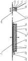
- Fig. 2a shows a longitudinal section of a single module
- Fig. 2b shows a cross-section of this module.
- Each module consists of a rigid trough 7 , a flexible sleeve 6 filled with a working fluid 5 , in which a half of the meander in the form of one pipe of the meander piping and one compensating loop 4 are placed.
- the working fluid 5 fills the flexible sleeve 6 in such a volume that the structural plate 8 applied on the trough from above adheres to it as much as possible over its entire surface.
- the rigid trough is "covered” by the structural plate 8 to which it is pressed, and the flexible sleeve 6 is flattened against the surface of the structural plate 8 ).
- an elastic band 11 is placed, into which the elastic sleeve 6 is pressed to an extent proportional to the thrust of the working fluid 5 .
- This band under given temperature conditions, flexes under the influence of the increasing thrust force of the working fluid 5 in the flexible sleeve 6 , and thus ensures a stable pressure of the working fluid 5 and protects the sleeve 6 from possible damage.
- the piping counterparts channelising solar streams of the meander piping and the compensating loops 4 of the loop piping 2 , 3 , 4 are made in the composite structural plate 8 as channels. These channels are located in one part of the metal plate 8 and are covered by another part of this plate which is of metal but can also be of glass. However, the channel inputs and outputs that are connected to the input collector 2 and the output collector 3 are routed backwards beyond the back plane of the plate 8 .
- the input collector 2 and the output collector 3 of the loop piping 2 , 3 , 4 are thus located outside the structural plate 8 on the opposite side thereof with respect to the back plane of the plate on which photovoltaic cells 16 are deposited.
- the plate 8 is integrated on one side with photovoltaic cells (preferably deposited directly thereon or alternatively glued as so-called "laminates"), and on the other side (from behind) with a thermally insulating composite structural plate.
- FIG. 3 of the drawing An exemplary method for controlling the temperature of the heat exchanger according to the invention is illustrated in Fig. 3 of the drawing.
- This method was used in a solar renewable energy installation based on a hybrid PVT photovoltaic panel with heat recovery located on the roof and façade of a detached house having a surface of 120 m 2 .
- the meander piping 1 of the heat exchanger is incorporated in a solar heating circuit 12 of a domestic hot water storage tank 13
- the loop piping 2 , 3 , 4 is connected to a phase energy storage 15 by means of a solar cooling circuit 14 .
- the installation of photovoltaic cells 16 in a solar electric circuit 17 is connected to an electrical energy storage tank 18 .
- the phase energy storage 15 is located in a lower source circuit 19 of a heat pump 20 and the electrical energy storage tank 18 is connected to a drive system of the heat pump 20 by means of an electrical supply circuit 21 .
- the temperature of the solar fluid at the output of the heating piping 1 of the heat exchanger is measured by means of the meander temperature sensor 9 . If the temperature at the output of the heating piping is higher than the permissible domestic hot water charging temperature, approx. 60 °C (which occurs during periods of high exposure to sunlight), the solar fluid flow is opened at the input of the collector 2 of the cooling piping 2 , 3 , 4 and with the solar fluid, the temperature of which at the input of this collector is approx.
- the solar fluid in the heating pipe is cooled via the structural plate 8 (or the working fluid 5 in the flexible sleeve 6 ) to a temperature not higher than the permissible temperature for charging the domestic hot water storage tank 13 , i.e. 60 °C, but not lower than the minimum permissible temperature for charging the domestic hot water storage tank, i.e. 45 °C, and the cooled solar fluid is charged to the domestic hot water storage tank until it is fully charged.
- the temperature at the output of the heating meander piping is lower than the lowest permissible domestic hot water charging temperature of approx. 45 °C, but higher than the break-even point temperature of approx.
- Cooling is carried out by transporting the low-temperature thermal energy of the heated structural plate 8 by means of the solar cooling circuit 14 from the heat exchanger to the phase energy storage 15 in the form of a tank containing approx. 30 tonnes of water having a liquid water temperature of 0 °C. Cooling is carried out until the temperature at the output of the output collector 3 is lowered to the break-even point temperature, i.e. 4 °C.
- the conditions affecting the balance of thermal energy include the heating effect of absorbed energy from solar radiation, the effect of energy of heated conductive paths that transport electrical energy from the photovoltaic cells 16 , the effect of the environment (including, but not limited to, the energy of condensation of water vapour from the air (phase transition) below the dew point temperature of the solar converter, the effect of wind, rain energy and the effect by thermal conduction of energy contained in the surrounding air of varying temperature etc.), and in particular the effect of the cooling loop piping 2 , 3 , 4 of the heat exchanger according to the invention.
- the operation of the solar renewable energy source equipped with the exchanger according to the invention results in the generation of a maximum value of electrical energy by the photovoltaic cells 16 , by ensuring a temperature range suitable for a given photovoltaic cell material and allows operation at temperatures below the dew point temperature. This is possible because the balance of energies affecting the operating temperature of such a cell material is carried out in a controlled manner, by adjusting the amount of cooling stream in the solar cooling circuit 14 on the basis of indications of the loop temperature sensor 10 .
- the electrical energy generated by the photovoltaic cells 16 is directed by means of the solar electric circuit 17 to a daily storage 18 , from which, for example, an electric car is recharged and, after conversion to alternating current by means of an inverter, is used for the ongoing supply of domestic appliances and the heat pump. Excess energy on a prosumer basis can be transmitted to the national electricity grid.
Landscapes
- Engineering & Computer Science (AREA)
- Physics & Mathematics (AREA)
- Life Sciences & Earth Sciences (AREA)
- Sustainable Development (AREA)
- Sustainable Energy (AREA)
- Thermal Sciences (AREA)
- Chemical & Material Sciences (AREA)
- Combustion & Propulsion (AREA)
- Mechanical Engineering (AREA)
- General Engineering & Computer Science (AREA)
- Photovoltaic Devices (AREA)
- Steam Or Hot-Water Central Heating Systems (AREA)
Applications Claiming Priority (1)
| Application Number | Priority Date | Filing Date | Title |
|---|---|---|---|
| PL437738A PL244004B1 (pl) | 2021-04-28 | 2021-04-28 | Wymiennik ciepła konwerterów słonecznych oraz sposób regulacji temperatury takiego wymiennika ciepła |
Publications (1)
| Publication Number | Publication Date |
|---|---|
| EP4083534A1 true EP4083534A1 (fr) | 2022-11-02 |
Family
ID=81580992
Family Applications (1)
| Application Number | Title | Priority Date | Filing Date |
|---|---|---|---|
| EP22164243.2A Pending EP4083534A1 (fr) | 2021-04-28 | 2022-03-24 | Échangeur de chaleur pour convertisseurs solaires et procédé de contrôle de la température d'un tel échangeur de chaleur |
Country Status (2)
| Country | Link |
|---|---|
| EP (1) | EP4083534A1 (fr) |
| PL (1) | PL244004B1 (fr) |
Citations (6)
| Publication number | Priority date | Publication date | Assignee | Title |
|---|---|---|---|---|
| US4102325A (en) * | 1977-05-04 | 1978-07-25 | Daystar Corporation | Temperature control in solar-to-thermal energy converters |
| DE2826937A1 (de) * | 1978-06-20 | 1980-01-03 | Heliotherm Ag | Flachkollektor zur erwaermung fluessiger medien |
| DE102006021119A1 (de) * | 2005-05-04 | 2006-12-28 | Nau Gmbh Umwelt- Und Energietechnik | Wärmekollektor und Wärmekollektorsystem |
| EP2182302A2 (fr) * | 2008-10-24 | 2010-05-05 | Fraunhofer-Gesellschaft zur Förderung der angewandten Forschung e.V. | Collecteur solaire doté d'une fonction de refroidissement |
| US20120291770A1 (en) * | 2010-01-18 | 2012-11-22 | Tigi Ltd. | System and method for temperature limiting in a sealed solar energy collector |
| DE102011053526A1 (de) * | 2011-09-12 | 2013-03-14 | SCHÜCO International KG | Absorber für eine Solarthermieanlage |
Family Cites Families (2)
| Publication number | Priority date | Publication date | Assignee | Title |
|---|---|---|---|---|
| CN107957143B (zh) * | 2017-12-21 | 2024-03-19 | 武汉博茗低碳产业股份有限公司 | 高效太阳能集热器 |
| CN111566415B (zh) * | 2017-12-21 | 2021-11-16 | 国迪瓦利有限公司 | 紧凑型太阳能收集器 |
-
2021
- 2021-04-28 PL PL437738A patent/PL244004B1/pl unknown
-
2022
- 2022-03-24 EP EP22164243.2A patent/EP4083534A1/fr active Pending
Patent Citations (6)
| Publication number | Priority date | Publication date | Assignee | Title |
|---|---|---|---|---|
| US4102325A (en) * | 1977-05-04 | 1978-07-25 | Daystar Corporation | Temperature control in solar-to-thermal energy converters |
| DE2826937A1 (de) * | 1978-06-20 | 1980-01-03 | Heliotherm Ag | Flachkollektor zur erwaermung fluessiger medien |
| DE102006021119A1 (de) * | 2005-05-04 | 2006-12-28 | Nau Gmbh Umwelt- Und Energietechnik | Wärmekollektor und Wärmekollektorsystem |
| EP2182302A2 (fr) * | 2008-10-24 | 2010-05-05 | Fraunhofer-Gesellschaft zur Förderung der angewandten Forschung e.V. | Collecteur solaire doté d'une fonction de refroidissement |
| US20120291770A1 (en) * | 2010-01-18 | 2012-11-22 | Tigi Ltd. | System and method for temperature limiting in a sealed solar energy collector |
| DE102011053526A1 (de) * | 2011-09-12 | 2013-03-14 | SCHÜCO International KG | Absorber für eine Solarthermieanlage |
Also Published As
| Publication number | Publication date |
|---|---|
| PL244004B1 (pl) | 2023-11-20 |
| PL437738A1 (pl) | 2022-10-31 |
Similar Documents
| Publication | Publication Date | Title |
|---|---|---|
| Huang et al. | Performance evaluation of solar photovoltaic/thermal systems | |
| Shukla et al. | Cooling methodologies of photovoltaic module for enhancing electrical efficiency: A review | |
| Kumar et al. | Historical and recent development of photovoltaic thermal (PVT) technologies | |
| Sandnes et al. | A photovoltaic/thermal (PV/T) collector with a polymer absorber plate. Experimental study and analytical model | |
| Kamel et al. | Solar systems and their integration with heat pumps: A review | |
| KR101979659B1 (ko) | 건물일체형 태양광·태양열 시스템 | |
| Garg et al. | Experimental study on a hybrid photovoltaic-thermal solar water heater and its performance predictions | |
| EP1873843B1 (fr) | Installation photovoltaïque | |
| Chen et al. | Fabrication and laboratory-based performance testing of a building-integrated photovoltaic-thermal roofing panel | |
| US6630622B2 (en) | Combined solar electric power and liquid heat transfer collector panel | |
| Al-Joboory | Comparative experimental investigation of two evacuated tube solar water heaters of different configurations for domestic application of Baghdad-Iraq | |
| US20120060899A1 (en) | Collector for the generation of electrical and thermal energy | |
| US20050051208A1 (en) | System for transferring heat in a thermoelectric generator system | |
| Psomopoulos | Solar energy: Harvesting the sun’s energy for a sustainable future | |
| WO2011014120A2 (fr) | Système de toit et murs à fonctions multiples | |
| Noro et al. | Advancements in hybrid photovoltaic-thermal systems: performance evaluations and applications | |
| Das et al. | Performance investigation of transparent photovoltaic‐thermal collector with horizontal oscillating and rectangular spiral flow patterns | |
| Ceylan et al. | A new hybrid system design for thermal energy storage | |
| EP4083534A1 (fr) | Échangeur de chaleur pour convertisseurs solaires et procédé de contrôle de la température d'un tel échangeur de chaleur | |
| Bondarenko et al. | Photovoltaic Thermal Solar Collector for Autonomous and Energy Cluster Modes | |
| Pugsley et al. | Experimental characterisation of a flat panel integrated collector-storage solar water heater featuring a photovoltaic absorber and a planar liquid-vapour thermal diode | |
| US20130340431A1 (en) | Method and apparatus for collecting solar thermal energy | |
| US20250089566A1 (en) | Hybrid solar panel and system | |
| DE102010031764A1 (de) | Multithermosolarvakuumphotovoltaikspeicherpaneel mit integriertem fluidgekühltem Niedertemperatur- Thermoausgleichsspeicher sowie einer unterhalb des Thermoausgleichsspeicher angebrachten elektrische Energie speichernde Batterie und hochtransparenter Vakuumabdeckung als Glatt- oder Formrohr zur Dachdeckung und Fassadendämmung einschl. einer unterlegten Hartschaumisolierung | |
| Chow et al. | Energy performance of a solar hybrid collector system in a multistory apartment building |
Legal Events
| Date | Code | Title | Description |
|---|---|---|---|
| PUAI | Public reference made under article 153(3) epc to a published international application that has entered the european phase |
Free format text: ORIGINAL CODE: 0009012 |
|
| STAA | Information on the status of an ep patent application or granted ep patent |
Free format text: STATUS: THE APPLICATION HAS BEEN PUBLISHED |
|
| AK | Designated contracting states |
Kind code of ref document: A1 Designated state(s): AL AT BE BG CH CY CZ DE DK EE ES FI FR GB GR HR HU IE IS IT LI LT LU LV MC MK MT NL NO PL PT RO RS SE SI SK SM TR |
|
| STAA | Information on the status of an ep patent application or granted ep patent |
Free format text: STATUS: REQUEST FOR EXAMINATION WAS MADE |
|
| 17P | Request for examination filed |
Effective date: 20230428 |
|
| RBV | Designated contracting states (corrected) |
Designated state(s): AL AT BE BG CH CY CZ DE DK EE ES FI FR GB GR HR HU IE IS IT LI LT LU LV MC MK MT NL NO PL PT RO RS SE SI SK SM TR |
|
| STAA | Information on the status of an ep patent application or granted ep patent |
Free format text: STATUS: EXAMINATION IS IN PROGRESS |
|
| 17Q | First examination report despatched |
Effective date: 20240430 |
|
| GRAP | Despatch of communication of intention to grant a patent |
Free format text: ORIGINAL CODE: EPIDOSNIGR1 |
|
| STAA | Information on the status of an ep patent application or granted ep patent |
Free format text: STATUS: GRANT OF PATENT IS INTENDED |