EP4083547A1 - Kühlschrank - Google Patents
Kühlschrank Download PDFInfo
- Publication number
- EP4083547A1 EP4083547A1 EP20905168.9A EP20905168A EP4083547A1 EP 4083547 A1 EP4083547 A1 EP 4083547A1 EP 20905168 A EP20905168 A EP 20905168A EP 4083547 A1 EP4083547 A1 EP 4083547A1
- Authority
- EP
- European Patent Office
- Prior art keywords
- evaporator
- refrigerant
- compressor
- refrigerant pipe
- defrosting
- Prior art date
- Legal status (The legal status is an assumption and is not a legal conclusion. Google has not performed a legal analysis and makes no representation as to the accuracy of the status listed.)
- Withdrawn
Links
Images


Classifications
-
- F—MECHANICAL ENGINEERING; LIGHTING; HEATING; WEAPONS; BLASTING
- F25—REFRIGERATION OR COOLING; COMBINED HEATING AND REFRIGERATION SYSTEMS; HEAT PUMP SYSTEMS; MANUFACTURE OR STORAGE OF ICE; LIQUEFACTION SOLIDIFICATION OF GASES
- F25B—REFRIGERATION MACHINES, PLANTS OR SYSTEMS; COMBINED HEATING AND REFRIGERATION SYSTEMS; HEAT PUMP SYSTEMS
- F25B47/00—Arrangements for preventing or removing deposits or corrosion, not provided for in another subclass
- F25B47/02—Defrosting cycles
- F25B47/022—Defrosting cycles hot gas defrosting
-
- F—MECHANICAL ENGINEERING; LIGHTING; HEATING; WEAPONS; BLASTING
- F25—REFRIGERATION OR COOLING; COMBINED HEATING AND REFRIGERATION SYSTEMS; HEAT PUMP SYSTEMS; MANUFACTURE OR STORAGE OF ICE; LIQUEFACTION SOLIDIFICATION OF GASES
- F25B—REFRIGERATION MACHINES, PLANTS OR SYSTEMS; COMBINED HEATING AND REFRIGERATION SYSTEMS; HEAT PUMP SYSTEMS
- F25B40/00—Subcoolers, desuperheaters or superheaters
-
- F—MECHANICAL ENGINEERING; LIGHTING; HEATING; WEAPONS; BLASTING
- F25—REFRIGERATION OR COOLING; COMBINED HEATING AND REFRIGERATION SYSTEMS; HEAT PUMP SYSTEMS; MANUFACTURE OR STORAGE OF ICE; LIQUEFACTION SOLIDIFICATION OF GASES
- F25B—REFRIGERATION MACHINES, PLANTS OR SYSTEMS; COMBINED HEATING AND REFRIGERATION SYSTEMS; HEAT PUMP SYSTEMS
- F25B49/00—Arrangement or mounting of control or safety devices
- F25B49/02—Arrangement or mounting of control or safety devices for compression type machines, plants or systems
-
- F—MECHANICAL ENGINEERING; LIGHTING; HEATING; WEAPONS; BLASTING
- F25—REFRIGERATION OR COOLING; COMBINED HEATING AND REFRIGERATION SYSTEMS; HEAT PUMP SYSTEMS; MANUFACTURE OR STORAGE OF ICE; LIQUEFACTION SOLIDIFICATION OF GASES
- F25D—REFRIGERATORS; COLD ROOMS; ICE-BOXES; COOLING OR FREEZING APPARATUS NOT OTHERWISE PROVIDED FOR
- F25D21/00—Defrosting; Preventing frosting; Removing condensed or defrost water
- F25D21/002—Defroster control
- F25D21/006—Defroster control with electronic control circuits
-
- F—MECHANICAL ENGINEERING; LIGHTING; HEATING; WEAPONS; BLASTING
- F25—REFRIGERATION OR COOLING; COMBINED HEATING AND REFRIGERATION SYSTEMS; HEAT PUMP SYSTEMS; MANUFACTURE OR STORAGE OF ICE; LIQUEFACTION SOLIDIFICATION OF GASES
- F25D—REFRIGERATORS; COLD ROOMS; ICE-BOXES; COOLING OR FREEZING APPARATUS NOT OTHERWISE PROVIDED FOR
- F25D21/00—Defrosting; Preventing frosting; Removing condensed or defrost water
- F25D21/06—Removing frost
-
- F—MECHANICAL ENGINEERING; LIGHTING; HEATING; WEAPONS; BLASTING
- F25—REFRIGERATION OR COOLING; COMBINED HEATING AND REFRIGERATION SYSTEMS; HEAT PUMP SYSTEMS; MANUFACTURE OR STORAGE OF ICE; LIQUEFACTION SOLIDIFICATION OF GASES
- F25D—REFRIGERATORS; COLD ROOMS; ICE-BOXES; COOLING OR FREEZING APPARATUS NOT OTHERWISE PROVIDED FOR
- F25D2700/00—Means for sensing or measuring; Sensors therefor
- F25D2700/10—Sensors measuring the temperature of the evaporator
-
- Y—GENERAL TAGGING OF NEW TECHNOLOGICAL DEVELOPMENTS; GENERAL TAGGING OF CROSS-SECTIONAL TECHNOLOGIES SPANNING OVER SEVERAL SECTIONS OF THE IPC; TECHNICAL SUBJECTS COVERED BY FORMER USPC CROSS-REFERENCE ART COLLECTIONS [XRACs] AND DIGESTS
- Y02—TECHNOLOGIES OR APPLICATIONS FOR MITIGATION OR ADAPTATION AGAINST CLIMATE CHANGE
- Y02B—CLIMATE CHANGE MITIGATION TECHNOLOGIES RELATED TO BUILDINGS, e.g. HOUSING, HOUSE APPLIANCES OR RELATED END-USER APPLICATIONS
- Y02B30/00—Energy efficient heating, ventilation or air conditioning [HVAC]
- Y02B30/70—Efficient control or regulation technologies, e.g. for control of refrigerant flow, motor or heating
Definitions
- the present invention relates to a refrigerator, and in particular, to a refrigerator defrosted by hot gas.
- each storage chamber is cooled to a desired refrigerating temperature range or freezing temperature range by blowing air cooled by an evaporator in a refrigerating cycle to each storage chamber.
- frost may be formed on a surface of the evaporator. Heat transfer between the evaporator and the air and air supply may be hindered when thick frost is generated on the surface of the evaporator. Therefore, operation of defrosting the evaporator is periodically performed during operation of the refrigerator.
- a defrosting heater disposed below the evaporator is energized to melt and remove the frost formed on the surface of the evaporator.
- a hot gas defrosting refrigerator also arises, in which the defrosting operation is performed by supplying, to the evaporator, a high temperature refrigerant compressed by a compressor of the refrigerating cycle.
- the hot gas defrosting refrigerator due to avoidance of heat generation by energization, a structure of the refrigerator may be simplified, and defrosting energy may be reduced.
- the hot gas defrosting refrigerator is described in the following patent documents 1 to 4: [patent document 1] Japanese patent No. 5369157 ; [patent document 2] Japanese patent No. 4837068 ; [patent document 3] Japanese patent No. 5253223 ; [patent document 4] Japanese patent No. 6545252 .
- the present invention is intended to provide a refrigerator preventing liquid backflow in a hot gas defrosting method.
- the present invention provides a technical solution as follows.
- the refrigerator includes: a storage chamber; a cooling chamber for accommodating air blown to the storage chamber; a refrigerating cycle having a compressor, a condenser, an expansion device, and an evaporator, the air accommodated in the cooling chamber being cooled by the evaporator; a defrosting heating unit for heating the evaporator to defrost; and a control unit for controlling actions of the refrigerating cycle and the defrosting heating unit; wherein when the evaporator is defrosted, the control unit heats the evaporator by the defrosting heating unit and supplies, to the evaporator, a refrigerant compressed at the compressor and not passing through the condenser.
- the refrigerant at the evaporator may be prevented from being liquefied.
- the compressor, the condenser, the expansion device, and the evaporator are connected with each other by refrigerant pipes; a switching portion is mounted in a middle of the refrigerant pipe for connecting the compressor and the condenser; the switching portion has a refrigerant inlet, a first refrigerant outlet, and a second refrigerant outlet; the refrigerant pipes include a first refrigerant pipe for connecting the compressor and the refrigerant inlet of the switching portion, a second refrigerant pipe for connecting the first refrigerant outlet of the switching portion and the condenser, a third refrigerant pipe for connecting the condenser and the expansion device, a fourth refrigerant pipe for connecting the expansion device and the evaporator, a fifth refrigerant pipe for connecting the second refrigerant outlet of the switching portion and a middle of the fourth refrigerant pipe, and a sixth refrigerant pipe for connecting the evaporator and the compressor
- the fifth refrigerant pipe is thermally connected with the sixth refrigerant pipe.
- the refrigerant passing through the evaporator may be prevented from being returned to the compressor in a liquid state due to an active heat exchange between the fifth refrigerant pipe in which the high temperature refrigerant compressed at the compressor flows and the sixth refrigerant pipe in which the refrigerant passing through the evaporator flows.
- the control unit increases an operation frequency of the compressor in response to a temperature increase of the evaporator when the refrigerant compressed at the compressor and not passing through the condenser is supplied to the evaporator.
- liquefaction of the high temperature refrigerant at the evaporator may be further prevented by slowly increasing the operation frequency of the compressor in the defrosting process.
- a refrigerator 10 according to an embodiment of the present invention will be described in detail based on the accompanying drawings.
- the same members are denoted by the same reference numerals in principle, and repeated descriptions are omitted.
- respective directions of up, down, front, rear, left, and right are used as appropriate, and left and right indicate the left and right when the refrigerator 10 is viewed from the front.
- the refrigerator 10 is exemplified as a refrigerator having a freezing chamber and a refrigerating chamber, but a refrigerator having only a freezing chamber or a refrigerator having only a refrigerating chamber may be adopted as the refrigerator 10.
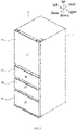
- FIG. 1 is a perspective view of the refrigerator 10 according to the embodiment of the present invention as viewed from the right front side.
- the refrigerator 10 has a thermal insulation cabinet 11 and a storage chamber formed inside the thermal insulation cabinet 11.
- As the storage chambers there exist a refrigerating chamber 12 and a freezing chamber 13 from the upper side.
- An upper section of a front opening of the refrigerating chamber 12 is closed by a thermal insulation door 18, and a lower section thereof is closed by a thermal insulation door 19.
- An upper section of a front opening of the freezing chamber 13 is closed by a thermal insulation door 20, and a lower section thereof is closed by a thermal insulation door 21.
- the thermal insulation door 18 is configured as a revolving door, and the thermal insulation doors 19, 20, and 21 are configured as pull-out doors.
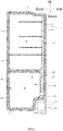
- FIG. 2 is a side sectional view integrally showing the refrigerator 10.
- the thermal insulation cabinet 11 includes an outer cabinet 111 made of a steel plate bent into a predetermined shape; an inner cabinet 112 made of a synthetic resin plate, the inner cabinet being disposed on an inner side spaced apart from the outer cabinet 111; and a thermal insulation material 113 with which a space between the outer cabinet 111 and the inner cabinet 112 is filled.
- a cooling chamber 115 is formed on a rear side of the freezing chamber 13, and the freezing chamber 13 is separated from the cooling chamber 115 by a partition 29.
- An evaporator 164 as a cooler is provided inside the cooling chamber 115.
- a mechanical chamber 14 is formed at the rear of a lower end side of the refrigerator 10 by partition, and a compressor 161 is arranged in the mechanical chamber 14.
- the evaporator 164 and the compressor 161 form a refrigerant compression refrigerating cycle 16.
- the refrigerating cycle 16 includes the compressor 161, a condenser 162 described later, an expansion device 163 described later, and the evaporator 164 described later.
- the refrigerating cycle 16 By operating the refrigerating cycle 16, cold air inside the cooling chamber 115 is cooled by the evaporator 164, and the cold air is blown to each storage chamber to bring a temperature inside each storage chamber into a predetermined cooling temperature range.
- the components forming the refrigerating cycle 16 are connected with each other by refrigerant pipes 23 described later, and the refrigerant pipe 23 is made of a metal pipe, such as a copper pipe, or the like. A structure of the refrigerant pipe 23 will be described with reference to FIG. 3 , or the like.
- a blower 27 is arranged on an upper side of the evaporator 164.
- the blower 27 is configured as an axial flow blower or a centrifugal blower, and blows the cold air inside the cooling chamber 115 cooled by the evaporator 164 to the refrigerating chamber 12 and the freezing chamber 13.
- a defrosting heating unit 117 is arranged below the evaporator 164.
- the defrosting heating unit 117 is configured as a heater generating heat when energized.
- the evaporator 164 is effectively defrosted by cooperatively using hot gas defrosting operation and the defrosting heating unit 117.
- a cover device for closing the cooling chamber 115 during the defrosting operation is provided near the blower 27.
- An air supply passage 118 is formed upwards from the cooling chamber 115.
- the air supply passage 118 has an opening formed therein for blowing the cold air to the refrigerating chamber 12.
- the cold air cooling the refrigerating chamber 12 is returned to the cooling chamber 115 through an air return passage (not shown), thus cooling the refrigerating chamber 12 to a specified refrigerating temperature range.
- a part of the blown cold air is blown to the freezing chamber 13 by the control unit 17 through an opening formed in an upper portion of the partition 29, and the cold air cooling the freezing chamber 13 is returned to the cooling chamber 115 through an opening formed in a lower portion of the partition 29.
- the freezing chamber 13 is cooled to a specified freezing temperature range.
- frost is generated at the evaporator 164 and blocks heat transfer and air flow of the evaporator 164, thus periodically defrosting the evaporator 164.
- the defrosting operation the operation of cooling the refrigerating chamber 12 and the freezing chamber 13 by the refrigerating cycle 16 is stopped, air supply by the blower 27 is stopped, and the evaporator 164 is defrosted by the hot gas defrosting operation by the refrigerating cycle 16 and heating operation by the defrosting heating unit 117. After the defrosting operation, the action of cooling the refrigerating chamber 12 and the freezing chamber 13 described above is resumed.
- FIG. 3(A) is a schematic diagram showing the refrigerating cycle 16 during the cooling operation
- FIG. 3(B) is a schematic diagram showing the refrigerating cycle 16 during the defrosting operation.
- the refrigerating cycle 16 mainly includes the compressor 161, the condenser 162, the expansion device 163, and the evaporator 164.
- a capillary tube or an expansion valve may be used as the expansion device 163.
- the components forming the refrigerating cycle 16 are connected by the refrigerant pipes 23.
- a switching portion 22 is provided in a middle of the refrigerant pipe 23.
- the switching portion 22 is configured as a so-called three-way valve, and includes a refrigerant inlet 221 into which a refrigerant flows as well as a first refrigerant outlet 222 and a second refrigerant outlet 223 from which the refrigerant selectively flows out.
- the refrigerant pipes 23 include a first refrigerant pipe 231, a second refrigerant pipe 232, a third refrigerant pipe 233, a fourth refrigerant pipe 234, a fifth refrigerant pipe 235, and a sixth refrigerant pipe 236.
- the compressor 161 is connected with the refrigerant inlet 221 of the switching portion 22 by the first refrigerant pipe 231.
- the first refrigerant outlet 222 of the switching portion 22 is connected with the condenser 162 by the second refrigerant pipe 232.
- the condenser 162 is connected with the expansion device 163 by the third refrigerant pipe 233.
- the expansion device 163 is connected with the evaporator 164 by the fourth refrigerant pipe 234.
- a bypass connection is performed on the second refrigerant outlet 223 of the switching portion 22 and a middle of the fourth refrigerant pipe 234 by the fifth refrigerant pipe 235.
- the evaporator 164 is connected with the compressor 161 by the sixth refrigerant pipe 236.
- the fifth refrigerant pipe 235 is configured as a bypass pipe for supplying the high temperature refrigerant compressed at the compressor 161 to the evaporator 164 without passing through the condenser 162 and the expansion device 163.
- the sixth refrigerant pipe 236, the fifth refrigerant pipe 235, the third refrigerant pipe 233, the expansion device 163, and the fourth refrigerant pipe 234 come into thermal contact with each other by waxing, or the like.
- the high temperature refrigerant flowing in the fifth refrigerant pipe 235 may raise a temperature of the refrigerant flowing in the sixth refrigerant pipe 236, and liquid backflow may be prevented.
- the refrigerant sequentially flows through the compressor 161, the first refrigerant pipe 231, the refrigerant inlet 221 and the first refrigerant outlet 222 of the switching portion 22, the second refrigerant pipe 232, the condenser 162, the third refrigerant pipe 233, the expansion device 163, the fourth refrigerant pipe 234, the evaporator 164, the sixth refrigerant pipe 236, and the compressor 161.
- the refrigerant does not pass through the condenser 162 and the expansion device 163, but is introduced into the evaporator 164 in an original high temperature vapor state, which is achieved by closing the first refrigerant outlet 222 of the switching portion 22 while releasing the second refrigerant outlet 223.
- the refrigerant sequentially flows through the compressor 161, the first refrigerant pipe 231, the refrigerant inlet 221 and the second refrigerant outlet 223 of the switching portion 22, the fifth refrigerant pipe 235, the fourth refrigerant pipe 234, the evaporator 164, the sixth refrigerant pipe 236, and the compressor 161.
- the high temperature refrigerant not passing through the condenser 162 and the expansion device 163 may flow to the evaporator 164, thus melting the frost generated on a surface of the evaporator 164. Furthermore, due to the thermal contact between the sixth refrigerant pipe 236 and the fifth refrigerant pipe 235, the refrigerant cooled in the evaporator 164 and returned to the compressor 161 may be heated up and vaporized by the high temperature refrigerant passing through the fifth refrigerant pipe 235, and the liquid backflow may be prevented.
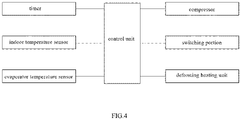
- FIG. 4 is a block diagram showing a connection structure of the refrigerator 10.
- the control unit 17 is configured as a calculation control element including a CPU, a RAM, a ROM, or the like.
- a timer 26, an indoor temperature sensor 24, and an evaporator temperature sensor 25 are connected at input terminals of the control unit 17.
- the timer 26 measures working times and stop times of various components forming the refrigerator 10, such as the compressor 161, the switching portion 22, and the defrosting heating unit 117.
- the indoor temperature sensor 24 measures internal temperatures of the refrigerating chamber 12 and the freezing chamber 13.
- the evaporator temperature sensor 25 measures a temperature of the evaporator 164 or the cooling chamber 115.
- the compressor 161, the switching portion 22, and the defrosting heating unit 117 are connected at output terminals of the control unit 17.
- the refrigerant is compressed by the compressor 161, a flow direction of the refrigerant is switched by the switching portion 22, and the defrosting heating unit 117 is configured as an electric heater for heating the evaporator 164.
- the control unit 17 executes a specified calculation based on input information input from the timer 26, the indoor temperature sensor 24, and the evaporator temperature sensor 25, and controls operation or switching actions of the compressor 161, the switching portion 22, and the defrosting heating unit 117 based on the calculation.
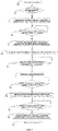
- FIG. 5 is a flow chart showing the defrosting operation
- FIG. 6 is a timing diagram showing the defrosting operation.
- FIG. 6 shows the temperature of the evaporator temperature sensor 25, opening and closing states of the first refrigerant outlet 222, opening and closing states of the second refrigerant outlet 223, opening and closing states of the defrosting heating unit 117 generating heat by energization, and an operation frequency of the compressor 161.
- step S10 the control unit 17 starts the defrosting operation. That is, referring to FIG. 2 , the blower 27 is stopped, the cooling operation by the refrigerating cycle 16 is stopped, and the cooling chamber 115 is closed using a damper, or the like.
- step S11 the control unit 17 judges whether the defrosting operation time measured by the timer 26 reaches a predetermined time, for example, 100 minutes.
- a predetermined time for example, 100 minutes.
- the control unit 17 proceeds to step S22 and ends the defrosting operation.
- the control unit 17 proceeds to step S12 and continues the defrosting operation.
- step S12 the control unit 17 energizes the defrosting heating unit 117 to generate heat, closes the first refrigerant outlet 222 of the switching portion 22, and also closes the second refrigerant outlet 223.
- the compressor 161 since the compressor 161 is stopped, no refrigerant is supplied to the evaporator 164.
- the cooling chamber 115 and the evaporator 164 are warmed by the defrosting heating unit 117, the frost of the evaporator 164 is melted slowly, and the evaporator 164 and the cooling chamber 115 are further warmed.
- Step S12 corresponds to T1 in the timing diagram of FIG. 6 .
- step S13 the control unit 17 judges whether the temperature of the evaporator 164 measured by the evaporator temperature sensor 25 is 0°C or above.
- the control unit 17 proceeds to step S14.
- the control unit 17 does not proceed to step S14, and the defrosting heating unit 117 continuously performs the heating operation.
- Step S13 corresponds to T1 to T2 in the timing diagram of FIG. 6 .
- step S14 the control unit 17 ends the energization of the defrosting heating unit 117, closes the first refrigerant outlet 222 of the switching portion 22, and opens the second refrigerant outlet 223.
- Step S14 corresponds to T2 in the timing diagram of FIG. 6 .
- step S15 the control unit 17 starts operation of the compressor 161 and sets an operation frequency of the compressor 161.
- the control unit 17 sets to "1".
- step S16 the control unit 17 judges whether the temperature of the evaporator 164 measured by the evaporator temperature sensor 25 is 2°C or above. When the temperature of the evaporator temperature sensor 25 is 2°C or above (i.e., yes in step S16), the control unit 17 proceeds to step S17. On the other hand, when the temperature of the evaporator temperature sensor 25 is lower than 2°C (i.e., no in step S16), the control unit 17 does not proceed to step S17.
- Step S16 corresponds to T2 to T3 in the timing diagram of FIG. 6 .
- step S17 the control unit 17 sets the operation frequency of the compressor 161. That is, the control unit 17 sets the operation frequency of the compressor 161 which is "1" in step S15 to "2". That is, a rotation frequency of the compressor 161 is doubled, and a flow rate of the high temperature refrigerant supplied to the evaporator 164 is increased, or the operation frequency of the compressor 161 is increased, and the flow rate of the high temperature refrigerant supplied to the evaporator 164 is doubled, thereby more actively performing the defrosting operation using the hot gas defrosting method.
- Step S16 corresponds to T3 in the timing diagram of FIG. 6 .
- step S18 the control unit 17 judges whether the temperature of the evaporator 164 measured by the evaporator temperature sensor 25 is 4°C or above. When the temperature of the evaporator temperature sensor 25 is 4°C or above (i.e., yes in step S18), the control unit 17 proceeds to step S19. On the other hand, when the temperature of the evaporator temperature sensor 25 is lower than 4°C (i.e., no in step S18), the control unit 17 does not proceed to step S19. Step S19 corresponds to T3 to T4 in the timing diagram of FIG. 6 .
- step S19 the control unit 17 increases the operation frequency of the compressor 161 every time the temperature of the evaporator 164 measured by the evaporator temperature sensor 25 is increased by 2°C. That is, when the temperature of the evaporator 164 measured by the evaporator temperature sensor 25 is changed to 4°C or above, as shown by T4 to T5 in FIG. 6 , the operation frequency of the compressor 161 is changed to "3". Furthermore, when the temperature of the evaporator 164 measured by the evaporator temperature sensor 25 is changed to 6°C or above, as shown by T5 to T6 in FIG. 6 , the operation frequency of the compressor 161 is changed to "4". In this way, the flow rate of the high temperature refrigerant supplied to the evaporator 164 is increased, and the hot gas defrosting operation is more actively performed.
- step S20 the control unit 17 judges whether the temperature of the evaporator 164 measured by the evaporator temperature sensor 25 is 8°C or above. When the temperature of the evaporator temperature sensor 25 is 8°C or above (i.e., yes in step S20), the control unit 17 determines that the defrosting operation is sufficiently performed, and proceeds to step S21. On the other hand, when the temperature of the evaporator temperature sensor 25 is lower than 8°C (i.e., no in step S20), the control unit 17 determines that the defrosting operation is insufficient, and returns to step S19.
- Step S20 corresponds to T5 to T6 in the timing diagram of FIG. 6 .
- step S21 the control unit 17 ends the operation of the compressor 161, closes the first refrigerant outlet 222 of the switching portion 22, closes the second refrigerant outlet 223, and proceeds to step S22 to end the defrosting operation.
- Step S21 corresponds to T6 in the timing diagram of FIG. 6 .
Landscapes
- Engineering & Computer Science (AREA)
- Physics & Mathematics (AREA)
- Mechanical Engineering (AREA)
- Thermal Sciences (AREA)
- General Engineering & Computer Science (AREA)
- Chemical & Material Sciences (AREA)
- Combustion & Propulsion (AREA)
- Defrosting Systems (AREA)
- Devices That Are Associated With Refrigeration Equipment (AREA)
Applications Claiming Priority (2)
| Application Number | Priority Date | Filing Date | Title |
|---|---|---|---|
| JP2019236809A JP7445287B2 (ja) | 2019-12-26 | 2019-12-26 | 冷蔵庫 |
| PCT/CN2020/138577 WO2021129654A1 (zh) | 2019-12-26 | 2020-12-23 | 冰箱 |
Publications (2)
| Publication Number | Publication Date |
|---|---|
| EP4083547A1 true EP4083547A1 (de) | 2022-11-02 |
| EP4083547A4 EP4083547A4 (de) | 2023-02-22 |
Family
ID=76575628
Family Applications (1)
| Application Number | Title | Priority Date | Filing Date |
|---|---|---|---|
| EP20905168.9A Withdrawn EP4083547A4 (de) | 2019-12-26 | 2020-12-23 | Kühlschrank |
Country Status (4)
| Country | Link |
|---|---|
| EP (1) | EP4083547A4 (de) |
| JP (1) | JP7445287B2 (de) |
| CN (1) | CN114867977B (de) |
| WO (1) | WO2021129654A1 (de) |
Families Citing this family (9)
| Publication number | Priority date | Publication date | Assignee | Title |
|---|---|---|---|---|
| JP7627178B2 (ja) * | 2021-06-25 | 2025-02-05 | 株式会社三共 | 遊技機 |
| JP7651391B2 (ja) * | 2021-06-25 | 2025-03-26 | 株式会社三共 | 遊技機 |
| JP7627177B2 (ja) * | 2021-06-25 | 2025-02-05 | 株式会社三共 | 遊技機 |
| JP7627180B2 (ja) * | 2021-06-25 | 2025-02-05 | 株式会社三共 | 遊技機 |
| KR20230010383A (ko) * | 2021-07-12 | 2023-01-19 | 엘지전자 주식회사 | 냉장고 및 그의 운전 제어방법 |
| KR20230010381A (ko) * | 2021-07-12 | 2023-01-19 | 엘지전자 주식회사 | 냉장고 |
| CN115682512A (zh) * | 2021-07-30 | 2023-02-03 | 青岛海尔电冰箱有限公司 | 冷藏冷冻装置及其控制方法 |
| JP7785328B2 (ja) * | 2021-12-13 | 2025-12-15 | アクア株式会社 | 冷蔵庫 |
| CN115950075B (zh) * | 2022-12-22 | 2024-09-24 | 珠海格力电器股份有限公司 | 制冷设备的化霜控制方法和装置 |
Family Cites Families (19)
| Publication number | Priority date | Publication date | Assignee | Title |
|---|---|---|---|---|
| JPS4837068B1 (de) | 1970-03-17 | 1973-11-08 | ||
| JPH0245252B2 (ja) | 1982-10-18 | 1990-10-08 | Nippon Technical | Teepupureeyanokyapusutankudokiko |
| JPH0674941B2 (ja) * | 1987-12-17 | 1994-09-21 | 三菱電機株式会社 | 冷凍サイクルの除霜制御方法 |
| CN2660433Y (zh) * | 2003-10-30 | 2004-12-01 | 河南新飞电器有限公司 | 一种自动融霜冰柜 |
| JP2005249254A (ja) * | 2004-03-03 | 2005-09-15 | Hitachi Home & Life Solutions Inc | 冷凍冷蔵庫 |
| CN100552341C (zh) * | 2005-06-30 | 2009-10-21 | 乐金电子(天津)电器有限公司 | 冰箱的除霜装置 |
| JP5253223B2 (ja) * | 2009-02-19 | 2013-07-31 | 三菱電機株式会社 | 冷蔵庫 |
| JP4770976B2 (ja) * | 2009-11-25 | 2011-09-14 | ダイキン工業株式会社 | コンテナ用冷凍装置 |
| US8739563B2 (en) * | 2011-04-21 | 2014-06-03 | Hamilton Sundstrand Corporation | Adaptable evaporator defrost logic for an aircraft |
| JP5369157B2 (ja) | 2011-09-27 | 2013-12-18 | 三菱電機株式会社 | 冷凍冷蔵庫 |
| JP5939764B2 (ja) * | 2011-11-02 | 2016-06-22 | 三菱電機株式会社 | ヒートポンプ装置及びヒートポンプ給湯機 |
| CN104697251B (zh) * | 2013-12-10 | 2018-04-27 | 苏州三星电子有限公司 | 一种冰箱制冷系统及冰箱 |
| KR20150075529A (ko) * | 2013-12-26 | 2015-07-06 | 동부대우전자 주식회사 | 냉장고의 냉각장치 및 그 제어 방법 |
| JP6032330B2 (ja) * | 2014-11-28 | 2016-11-24 | ダイキン工業株式会社 | 空調機 |
| CN205655568U (zh) * | 2016-03-31 | 2016-10-19 | 广州芯康医疗科技有限公司 | 一种带有电热和热气混合化霜功能的低温风冷制冷系统和低温风冷冰箱、低温风冷冷柜 |
| JP6320456B2 (ja) * | 2016-05-27 | 2018-05-09 | 三菱電機株式会社 | 冷蔵庫 |
| CN107917562A (zh) * | 2017-11-22 | 2018-04-17 | 广州芯康医疗科技有限公司 | 用于低温风冷制冷系统的热气和电热混合除霜系统和方法 |
| CN108413666B (zh) * | 2018-03-07 | 2021-01-08 | 骊阳(广东)节能科技股份有限公司 | 一种快速除霜的高效空气源热泵系统 |
| CN108826772B (zh) * | 2018-05-03 | 2020-11-17 | 广东美的暖通设备有限公司 | 化霜控制方法及系统 |
-
2019
- 2019-12-26 JP JP2019236809A patent/JP7445287B2/ja active Active
-
2020
- 2020-12-23 WO PCT/CN2020/138577 patent/WO2021129654A1/zh not_active Ceased
- 2020-12-23 CN CN202080090209.5A patent/CN114867977B/zh active Active
- 2020-12-23 EP EP20905168.9A patent/EP4083547A4/de not_active Withdrawn
Also Published As
| Publication number | Publication date |
|---|---|
| CN114867977B (zh) | 2023-10-27 |
| CN114867977A (zh) | 2022-08-05 |
| WO2021129654A1 (zh) | 2021-07-01 |
| JP2021105483A (ja) | 2021-07-26 |
| JP7445287B2 (ja) | 2024-03-07 |
| EP4083547A4 (de) | 2023-02-22 |
Similar Documents
| Publication | Publication Date | Title |
|---|---|---|
| CN114867977B (zh) | 冰箱 | |
| JPH1123135A (ja) | 除霜装置を具える冷蔵庫 | |
| AU2018202121B2 (en) | Refrigerator and method for controlling the same | |
| KR20150075529A (ko) | 냉장고의 냉각장치 및 그 제어 방법 | |
| AU2018202123B2 (en) | Refrigerator and method for controlling the same | |
| JP2017116224A (ja) | 冷蔵庫 | |
| JP2019039586A (ja) | 冷蔵庫 | |
| CN102997535B (zh) | 冰箱 | |
| US11313596B2 (en) | Evaporator and refrigerator having same | |
| CN211552170U (zh) | 制冷制热两用冰箱 | |
| KR100753501B1 (ko) | 연속냉각이 가능한 냉장고 | |
| CN203454532U (zh) | 制冷器具 | |
| CN107816832B (zh) | 冰箱 | |
| WO2020175824A1 (ko) | 냉장고의 제어 방법 | |
| WO2020175826A1 (ko) | 냉장고의 제어 방법 | |
| JP7522963B2 (ja) | 冷蔵庫 | |
| KR100310535B1 (ko) | 공랭식히트펌프 | |
| JP2019100566A (ja) | 冷蔵庫 | |
| KR100686764B1 (ko) | 면상히터 | |
| JPH0517580Y2 (de) | ||
| JP2008075939A (ja) | 冷蔵庫 | |
| JP2022125450A (ja) | 冷蔵庫 | |
| CN112066619A (zh) | 采用回收热化霜的冰箱 | |
| CN116465140B (zh) | 一种多热源立体分布式热气旁通除霜系统及控制方法 | |
| CN110131952A (zh) | 组合制冷器具 |
Legal Events
| Date | Code | Title | Description |
|---|---|---|---|
| STAA | Information on the status of an ep patent application or granted ep patent |
Free format text: STATUS: THE INTERNATIONAL PUBLICATION HAS BEEN MADE |
|
| PUAI | Public reference made under article 153(3) epc to a published international application that has entered the european phase |
Free format text: ORIGINAL CODE: 0009012 |
|
| STAA | Information on the status of an ep patent application or granted ep patent |
Free format text: STATUS: REQUEST FOR EXAMINATION WAS MADE |
|
| 17P | Request for examination filed |
Effective date: 20220330 |
|
| AK | Designated contracting states |
Kind code of ref document: A1 Designated state(s): AL AT BE BG CH CY CZ DE DK EE ES FI FR GB GR HR HU IE IS IT LI LT LU LV MC MK MT NL NO PL PT RO RS SE SI SK SM TR |
|
| A4 | Supplementary search report drawn up and despatched |
Effective date: 20230120 |
|
| RIC1 | Information provided on ipc code assigned before grant |
Ipc: F25B 40/00 20060101ALI20230116BHEP Ipc: F25B 49/02 20060101ALI20230116BHEP Ipc: F25B 47/02 20060101ALI20230116BHEP Ipc: F25D 21/06 20060101ALI20230116BHEP Ipc: F25D 21/08 20060101AFI20230116BHEP |
|
| DAV | Request for validation of the european patent (deleted) | ||
| DAX | Request for extension of the european patent (deleted) | ||
| GRAP | Despatch of communication of intention to grant a patent |
Free format text: ORIGINAL CODE: EPIDOSNIGR1 |
|
| STAA | Information on the status of an ep patent application or granted ep patent |
Free format text: STATUS: GRANT OF PATENT IS INTENDED |
|
| RIC1 | Information provided on ipc code assigned before grant |
Ipc: F25B 40/00 20060101ALI20241203BHEP Ipc: F25B 49/02 20060101ALI20241203BHEP Ipc: F25B 47/02 20060101ALI20241203BHEP Ipc: F25D 21/06 20060101ALI20241203BHEP Ipc: F25D 21/08 20060101AFI20241203BHEP |
|
| INTG | Intention to grant announced |
Effective date: 20241212 |
|
| STAA | Information on the status of an ep patent application or granted ep patent |
Free format text: STATUS: THE APPLICATION IS DEEMED TO BE WITHDRAWN |
|
| 18D | Application deemed to be withdrawn |
Effective date: 20250415 |