EP4083580A1 - Unité de capteur permettant de détecter des flux de gaz dans un bloc batterie ou dans une unité de batterie, bloc batterie, unité de batterie et procédé de détection du flux de gaz dans un bloc batterie ou dans une unité de batterie - Google Patents
Unité de capteur permettant de détecter des flux de gaz dans un bloc batterie ou dans une unité de batterie, bloc batterie, unité de batterie et procédé de détection du flux de gaz dans un bloc batterie ou dans une unité de batterie Download PDFInfo
- Publication number
- EP4083580A1 EP4083580A1 EP21171467.0A EP21171467A EP4083580A1 EP 4083580 A1 EP4083580 A1 EP 4083580A1 EP 21171467 A EP21171467 A EP 21171467A EP 4083580 A1 EP4083580 A1 EP 4083580A1
- Authority
- EP
- European Patent Office
- Prior art keywords
- resistance temperature
- battery
- temperature sensor
- sensor
- unit
- Prior art date
- Legal status (The legal status is an assumption and is not a legal conclusion. Google has not performed a legal analysis and makes no representation as to the accuracy of the status listed.)
- Withdrawn
Links
Images


Classifications
-
- G—PHYSICS
- G01—MEASURING; TESTING
- G01F—MEASURING VOLUME, VOLUME FLOW, MASS FLOW OR LIQUID LEVEL; METERING BY VOLUME
- G01F1/00—Measuring the volume flow or mass flow of fluid or fluent solid material wherein the fluid passes through a meter in a continuous flow
- G01F1/68—Measuring the volume flow or mass flow of fluid or fluent solid material wherein the fluid passes through a meter in a continuous flow by using thermal effects
- G01F1/684—Structural arrangements; Mounting of elements, e.g. in relation to fluid flow
- G01F1/688—Structural arrangements; Mounting of elements, e.g. in relation to fluid flow using a particular type of heating, cooling or sensing element
- G01F1/69—Structural arrangements; Mounting of elements, e.g. in relation to fluid flow using a particular type of heating, cooling or sensing element of resistive type
-
- B—PERFORMING OPERATIONS; TRANSPORTING
- B60—VEHICLES IN GENERAL
- B60L—PROPULSION OF ELECTRICALLY-PROPELLED VEHICLES; SUPPLYING ELECTRIC POWER FOR AUXILIARY EQUIPMENT OF ELECTRICALLY-PROPELLED VEHICLES; ELECTRODYNAMIC BRAKE SYSTEMS FOR VEHICLES IN GENERAL; MAGNETIC SUSPENSION OR LEVITATION FOR VEHICLES; MONITORING OPERATING VARIABLES OF ELECTRICALLY-PROPELLED VEHICLES; ELECTRIC SAFETY DEVICES FOR ELECTRICALLY-PROPELLED VEHICLES
- B60L3/00—Electric devices on electrically-propelled vehicles for safety purposes; Monitoring operating variables, e.g. speed, deceleration or energy consumption
- B60L3/0023—Detecting, eliminating, remedying or compensating for drive train abnormalities, e.g. failures within the drive train
- B60L3/0046—Detecting, eliminating, remedying or compensating for drive train abnormalities, e.g. failures within the drive train relating to electric energy storage systems, e.g. batteries or capacitors
-
- B—PERFORMING OPERATIONS; TRANSPORTING
- B60—VEHICLES IN GENERAL
- B60L—PROPULSION OF ELECTRICALLY-PROPELLED VEHICLES; SUPPLYING ELECTRIC POWER FOR AUXILIARY EQUIPMENT OF ELECTRICALLY-PROPELLED VEHICLES; ELECTRODYNAMIC BRAKE SYSTEMS FOR VEHICLES IN GENERAL; MAGNETIC SUSPENSION OR LEVITATION FOR VEHICLES; MONITORING OPERATING VARIABLES OF ELECTRICALLY-PROPELLED VEHICLES; ELECTRIC SAFETY DEVICES FOR ELECTRICALLY-PROPELLED VEHICLES
- B60L50/00—Electric propulsion with power supplied within the vehicle
- B60L50/50—Electric propulsion with power supplied within the vehicle using propulsion power supplied by batteries or fuel cells
- B60L50/60—Electric propulsion with power supplied within the vehicle using propulsion power supplied by batteries or fuel cells using power supplied by batteries
- B60L50/64—Constructional details of batteries specially adapted for electric vehicles
-
- B—PERFORMING OPERATIONS; TRANSPORTING
- B60—VEHICLES IN GENERAL
- B60L—PROPULSION OF ELECTRICALLY-PROPELLED VEHICLES; SUPPLYING ELECTRIC POWER FOR AUXILIARY EQUIPMENT OF ELECTRICALLY-PROPELLED VEHICLES; ELECTRODYNAMIC BRAKE SYSTEMS FOR VEHICLES IN GENERAL; MAGNETIC SUSPENSION OR LEVITATION FOR VEHICLES; MONITORING OPERATING VARIABLES OF ELECTRICALLY-PROPELLED VEHICLES; ELECTRIC SAFETY DEVICES FOR ELECTRICALLY-PROPELLED VEHICLES
- B60L58/00—Methods or circuit arrangements for monitoring or controlling batteries or fuel cells, specially adapted for electric vehicles
- B60L58/10—Methods or circuit arrangements for monitoring or controlling batteries or fuel cells, specially adapted for electric vehicles for monitoring or controlling batteries
- B60L58/24—Methods or circuit arrangements for monitoring or controlling batteries or fuel cells, specially adapted for electric vehicles for monitoring or controlling batteries for controlling the temperature of batteries
- B60L58/26—Methods or circuit arrangements for monitoring or controlling batteries or fuel cells, specially adapted for electric vehicles for monitoring or controlling batteries for controlling the temperature of batteries by cooling
-
- H—ELECTRICITY
- H01—ELECTRIC ELEMENTS
- H01M—PROCESSES OR MEANS, e.g. BATTERIES, FOR THE DIRECT CONVERSION OF CHEMICAL ENERGY INTO ELECTRICAL ENERGY
- H01M10/00—Secondary cells; Manufacture thereof
- H01M10/42—Methods or arrangements for servicing or maintenance of secondary cells or secondary half-cells
- H01M10/48—Accumulators combined with arrangements for measuring, testing or indicating the condition of cells, e.g. the level or density of the electrolyte
-
- H—ELECTRICITY
- H01—ELECTRIC ELEMENTS
- H01M—PROCESSES OR MEANS, e.g. BATTERIES, FOR THE DIRECT CONVERSION OF CHEMICAL ENERGY INTO ELECTRICAL ENERGY
- H01M50/00—Constructional details or processes of manufacture of the non-active parts of electrochemical cells other than fuel cells, e.g. hybrid cells
- H01M50/20—Mountings; Secondary casings or frames; Racks, modules or packs; Suspension devices; Shock absorbers; Transport or carrying devices; Holders
- H01M50/204—Racks, modules or packs for multiple batteries or multiple cells
-
- H—ELECTRICITY
- H01—ELECTRIC ELEMENTS
- H01M—PROCESSES OR MEANS, e.g. BATTERIES, FOR THE DIRECT CONVERSION OF CHEMICAL ENERGY INTO ELECTRICAL ENERGY
- H01M50/00—Constructional details or processes of manufacture of the non-active parts of electrochemical cells other than fuel cells, e.g. hybrid cells
- H01M50/20—Mountings; Secondary casings or frames; Racks, modules or packs; Suspension devices; Shock absorbers; Transport or carrying devices; Holders
- H01M50/258—Modular batteries; Casings provided with means for assembling
-
- H—ELECTRICITY
- H02—GENERATION; CONVERSION OR DISTRIBUTION OF ELECTRIC POWER
- H02J—ELECTRIC POWER NETWORKS; CIRCUIT ARRANGEMENTS OR SYSTEMS FOR SUPPLYING OR DISTRIBUTING ELECTRIC POWER; SYSTEMS FOR STORING ELECTRIC ENERGY
- H02J7/00—Circuit arrangements for charging or discharging batteries or for supplying loads from batteries
- H02J7/60—Circuit arrangements for charging or discharging batteries or for supplying loads from batteries including safety or protection arrangements
- H02J7/65—Circuit arrangements for charging or discharging batteries or for supplying loads from batteries including safety or protection arrangements against overtemperature
-
- H—ELECTRICITY
- H02—GENERATION; CONVERSION OR DISTRIBUTION OF ELECTRIC POWER
- H02J—ELECTRIC POWER NETWORKS; CIRCUIT ARRANGEMENTS OR SYSTEMS FOR SUPPLYING OR DISTRIBUTING ELECTRIC POWER; SYSTEMS FOR STORING ELECTRIC ENERGY
- H02J7/00—Circuit arrangements for charging or discharging batteries or for supplying loads from batteries
- H02J7/90—Regulation of charging or discharging current or voltage
- H02J7/971—Regulation of charging or discharging current or voltage the charge cycle being controlled or terminated in response to non-electric parameters
- H02J7/973—Regulation of charging or discharging current or voltage the charge cycle being controlled or terminated in response to non-electric parameters in response to degree of gas development in the battery
-
- H—ELECTRICITY
- H02—GENERATION; CONVERSION OR DISTRIBUTION OF ELECTRIC POWER
- H02J—ELECTRIC POWER NETWORKS; CIRCUIT ARRANGEMENTS OR SYSTEMS FOR SUPPLYING OR DISTRIBUTING ELECTRIC POWER; SYSTEMS FOR STORING ELECTRIC ENERGY
- H02J7/00—Circuit arrangements for charging or discharging batteries or for supplying loads from batteries
- H02J7/90—Regulation of charging or discharging current or voltage
- H02J7/971—Regulation of charging or discharging current or voltage the charge cycle being controlled or terminated in response to non-electric parameters
- H02J7/975—Regulation of charging or discharging current or voltage the charge cycle being controlled or terminated in response to non-electric parameters in response to temperature
- H02J7/977—Regulation of charging or discharging current or voltage the charge cycle being controlled or terminated in response to non-electric parameters in response to temperature of the battery
-
- B—PERFORMING OPERATIONS; TRANSPORTING
- B60—VEHICLES IN GENERAL
- B60L—PROPULSION OF ELECTRICALLY-PROPELLED VEHICLES; SUPPLYING ELECTRIC POWER FOR AUXILIARY EQUIPMENT OF ELECTRICALLY-PROPELLED VEHICLES; ELECTRODYNAMIC BRAKE SYSTEMS FOR VEHICLES IN GENERAL; MAGNETIC SUSPENSION OR LEVITATION FOR VEHICLES; MONITORING OPERATING VARIABLES OF ELECTRICALLY-PROPELLED VEHICLES; ELECTRIC SAFETY DEVICES FOR ELECTRICALLY-PROPELLED VEHICLES
- B60L2240/00—Control parameters of input or output; Target parameters
- B60L2240/40—Drive Train control parameters
- B60L2240/54—Drive Train control parameters related to batteries
- B60L2240/545—Temperature
-
- H—ELECTRICITY
- H01—ELECTRIC ELEMENTS
- H01M—PROCESSES OR MEANS, e.g. BATTERIES, FOR THE DIRECT CONVERSION OF CHEMICAL ENERGY INTO ELECTRICAL ENERGY
- H01M10/00—Secondary cells; Manufacture thereof
- H01M10/05—Accumulators with non-aqueous electrolyte
- H01M10/052—Li-accumulators
- H01M10/0525—Rocking-chair batteries, i.e. batteries with lithium insertion or intercalation in both electrodes; Lithium-ion batteries
-
- H—ELECTRICITY
- H01—ELECTRIC ELEMENTS
- H01M—PROCESSES OR MEANS, e.g. BATTERIES, FOR THE DIRECT CONVERSION OF CHEMICAL ENERGY INTO ELECTRICAL ENERGY
- H01M50/00—Constructional details or processes of manufacture of the non-active parts of electrochemical cells other than fuel cells, e.g. hybrid cells
- H01M50/20—Mountings; Secondary casings or frames; Racks, modules or packs; Suspension devices; Shock absorbers; Transport or carrying devices; Holders
- H01M50/249—Mountings; Secondary casings or frames; Racks, modules or packs; Suspension devices; Shock absorbers; Transport or carrying devices; Holders specially adapted for aircraft or vehicles, e.g. cars or trains
Definitions
- the invention relates to a sensor unit for detecting gas flows in a battery block or in a battery unit. Furthermore, the invention relates to a battery pack with a plurality of battery cells located in a housing. Furthermore, the invention relates to a battery unit with a plurality of battery blocks located in a battery unit housing. The invention also relates to a method for detecting gas flows in a battery block or in a battery unit.
- Lithium-ion batteries are currently considered to be storage devices with the highest energy density in relation to available accumulators. For this reason, lithium-ion batteries have been used for some time in mobile devices that are not permanently connected to an electrical network. The desire for ever larger batteries with high performance is increasing. To achieve this, individual lithium-ion cells are connected in series and in series to form battery blocks. However, it is known that short circuits can occur within individual cells during the operation of such battery blocks, which in turn can trigger chain reactions. Such safety-relevant faults, which are referred to as "thermal runaway”, must therefore be recognized early on in order to be able to initiate suitable countermeasures, such as immediately switching off the battery block in question.
- U.S. 2019/0379030 A1 proposes, for example, using a gas sensor to determine concentrations of a gas species, in particular CO 2 , CO, H 2 , O 2 , NO x , O 3 , H 2 O hydrocarbons (CH 4 ), in a gas circulation unit which is part of the battery system , to prove. Furthermore, a method is proposed that initiates countermeasures when abnormal conditions occur.
- a gas species in particular CO 2 , CO, H 2 , O 2 , NO x , O 3 , H 2 O hydrocarbons (CH 4 )
- KR 102 181 521 B proposes a battery module in which a gas cooling fan device is formed in the housing. This gas-cooling fan unit is switched off when it detects gases being released, which are produced when a battery cell is overcharged.
- EP 2 358 432 B1 proposes, however, a battery module that has a monitoring means.
- the concentration of a gas in the tempering fluid inside the battery housing is monitored with the aid of the monitoring means.
- a battery module which has a multiplicity of detection units within the battery module for the detection of gases.
- EP 2 797 158 A1 proposes a battery system consisting of multiple battery sub-units.
- Each battery sub-unit is equipped with a gas leak sensor located in the cooling gas flow outlet area, which detects abnormalities in the gas flow. On the basis of detected anomalies in the gas flow, it can be initiated, for example, that a discharge fan conveys more air volume out of the housing than a supply air fan conveys air volume into the housing.
- a further object of the present invention is to specify a further developed battery unit which is further developed in particular with regard to a sensor unit for detecting gas flows.
- a further object of the present invention is to specify a further developed method for detecting gas flows in a battery block and/or in a battery unit. With the help of a further developed method, a more rapid detection of the "thermal runaway" should be made possible in particular than is possible with previously known methods.
- this object is achieved with regard to a sensor unit by the subject matter of claim 1, with regard to a battery pack by the subject matter of patent claim 7, with regard to a battery unit by the subject matter of patent claim 10, and with regard to a method for detecting gas flows in a battery pack or in a battery unit by the subject matter of claim 13.
- the invention is based on the idea of specifying a sensor unit for detecting gas flows in a battery block or in a battery unit, the sensor unit having a carrier and at least one resistance temperature sensor.
- the at least one resistance temperature sensor has at least six sides, namely an upper side, a lower side and four end faces, with the resistance temperature sensor being connected to the carrier in such a way that the upper side, the lower side and at least two end sides can be flowed around by a gas at least in sections.
- the invention is thus based on the idea of connecting a resistance temperature sensor to a carrier in such a way that a gas can flow around the resistance temperature sensor at least in sections with regard to the upper side, the lower side and at least two end faces.
- top and bottom of a resistance temperature sensor are the sides that point upwards (top) or downwards (bottom) when a sensor unit is placed on an (imaginary) horizontal storage surface.
- the storage takes place in such a way that the carrier of the sensor unit rests on the (imaginary) horizontal storage surface.
- the four end faces are the four additional sides of an essentially cuboid element.
- the four end faces form the four further peripheral sides of a cuboid element.
- the four end faces are formed essentially perpendicularly to the top and to the bottom. Depending on the manufacturing process, there may be corresponding variants with regard to a vertical arrangement.
- the at least one resistance temperature sensor is preferably connected directly or indirectly to the carrier on at most two sections of one side, preferably on the underside.
- the described connection of the resistance temperature sensor to the carrier relates primarily to the structural connection to the carrier.
- the connection relates to the placement of the resistance temperature sensor in relation to the carrier and the mounting.
- the connection does not primarily concern the electrical connection of the RTD to the carrier.
- the structural connection described can also relate to an electrical connection or enable such a combined connection (structural and electrical).
- the resistance temperature sensor is connected to the carrier on at most two sections of one side, preferably on the underside, it is possible for a gas to flow completely around the upper side and the four end faces. Due to the connection of the resistance temperature sensor to the carrier, a gas can flow around the underside at least in sections, preferably predominantly. With such a fastening configuration, a gas can flow completely around the resistance temperature sensor, with the exception of the two sections for connecting the resistance temperature sensor.
- the resistance temperature sensor is connected to the carrier by means of adhesion.
- the resistance temperature sensor can be glued to the carrier.
- the resistance temperature sensor in a further embodiment of the invention it is possible for the resistance temperature sensor to be connected to the carrier by means of a sintered material.
- the connection of the resistance temperature sensor to the carrier it is possible for the connection of the resistance temperature sensor to the carrier to constitute an electrical contact at the same time. It is possible here for the resistance temperature sensor to have at least one, preferably at least two, contact pads. In such an embodiment of the invention, the resistance temperature sensor is preferably designed as a flip-chip sensor. In this case, a resistance temperature sensor has two contact pads on one side, preferably on the underside. The resistance temperature sensors are mechanically and electrically connected, for example, to further contact pads of the carrier via these contact pads. The actual connection is preferably made using a metal-containing sinter paste or a conductive adhesive.
- the carrier prefferably has at least two fastening straps, with the at least two fastening straps being designed to face one another and the at least one resistance temperature sensor being directly or indirectly mechanically connected to the fastening straps.
- the resistance temperature sensor is preferably connected to the two fastening lugs mentioned on at most two sections of one side, preferably the underside.
- Fastening lugs of a carrier are preferably to be understood as lugs protruding (laterally) from further carrier sections.
- no further carrier material is formed between at least two fastening straps.
- the at least two fastening straps are spaced apart from one another, with the distance between the at least two fastening straps or the respective mutually arranged fastening straps being designed as a free space or as a material recess.
- At least one fastening tab has a smaller thickness and/or a smaller cross-section, at least in sections, in comparison to adjacent carrier sections.
- the at least two fastening straps each have an im Compared to adjoining carrier sections at least partially smaller thickness and / or a smaller cross-section. Additional space is thus made available in the region of the reduced thickness or the reduced cross section, which is advantageous with regard to an improved gas flow.
- the flow of gas around the resistance temperature sensor can be turbulent or laminar, depending on the gas velocity occurring at the sensor location.
- the resistance temperature sensor which can be freely flowed around over significant sections and typically extends in the millimeter range, represents a small obstacle in terms of flow dynamics, which can induce turbulent gas flow components and can promote heat transfer to the gas phase even more.
- the at least one resistance temperature sensor is connected to the carrier according to the invention in such a way that the resistance temperature sensor is in good thermal contact with the surrounding gas and at the same time the heat dissipation from the resistance temperature sensor to the carrier is minimal.
- the fastening tabs described improve this point considerably.
- the sensor unit has at least two resistance temperature sensors.
- the carrier prefferably has two longitudinal ends, with a resistance temperature sensor being formed at each longitudinal end.
- two resistance temperature sensors are arranged at two longitudinal ends of the support of the sensor unit.
- a sensor unit has at least two resistance temperature sensors, the resistance temperature sensors are preferably of the same design.
- Low-mass temperature sensors are particularly suitable as resistance temperature sensors.
- the at least one resistance temperature sensor is particularly preferably a platinum-based temperature sensor, such as a Pt1000 or Pt10000 sensor.
- Such sensors have both a high temperature coefficient and a high basic resistance.
- the basic resistance R 0 is, for example, 1000 ohms or even 10000 ohms at 0°C. Therefore, such sensors are very sensitive due to high temperature coefficients and due to a high basic resistance. Because of this, small temperature changes can be detected extremely accurately.
- low-mass temperature sensors have a fast response time and high self-heating.
- the self-heating can be greater than 180 K/W.
- Low-mass temperature sensors are particularly suitable for use in a sensor unit according to the invention, since both the sensitivity and the accuracy are constant over the entire relevant temperature range.
- only those sections of the carrier that are used to connect the resistance temperature sensor to the carrier are formed below the underside of the at least one resistance temperature sensor.
- a free space is preferably formed below the underside of the at least one resistance temperature sensor. This free space is visible in particular when the sensor unit is placed on an (imaginary) storage area in such a way that the carrier rests on the storage area.
- the vertical extension preferably no sections of the carrier are formed between the underside of the resistance temperature sensor and the (imaginary) bearing surface. Areas of overlap with sections of the carrier are preferably formed only with respect to the connecting sections of the resistance temperature sensor with the carrier.
- the at least one RTD is positioned on and bonded to the carrier such that the RTD is in good thermal contact with the surrounding gas while minimizing heat dissipation from the RTD to the carrier.
- this is achieved in that the carrier has at least one cutout or indentation, with the at least one resistance temperature sensor spanning this cutout or indentation.
- the resistance temperature sensor is preferably only connected to the carrier at two sections, each of which forms two lateral end sections. This relates to a structural connection of the resistance temperature sensor to the carrier and not necessarily an electrical connection, although a combined electrical connection is not excluded.
- Such a connection of the at least one resistance temperature sensor to the carrier has several advantages. On the one hand, such a connection of the resistance temperature sensor to the carrier is relatively stiff and prevents the resistance temperature sensor from mechanically oscillating relative to the carrier. Furthermore, because of this connection, a large proportion of the resistance temperature sensor can be designed so that a gas can flow around it. In particular, both the top and the bottom can be in direct thermal contact with the surrounding gas for the most part.
- a further reduction in the heat conduction from the at least one resistance temperature sensor to the carrier is realized in that a possible fastening strap is also designed with relatively little mass. It is possible for the preferably at least one fastening tab to enable electrical contact to be made with the at least one resistance temperature sensor at the same time.
- At least one fastening tab can have a smaller thickness than adjacent carrier sections. Furthermore, it is possible for the at least one fastening strap to have a smaller cross section in comparison to an adjoining carrier section. In summary, this enables the formation of a low-mass fastening strap. Furthermore, it is possible that at least one Fastening strap on the surface, ie on the surface facing the resistance temperature sensor, has at least one lead or at least one contact pad.
- the carrier and/or the fastening tabs may have perforations.
- perforations is meant, for example, holes in the carrier and/or mounting tabs, preferably near the junctions with the RTD. This makes it possible to reduce the relevant cross-section of the carrier and/or the fastening tabs and to minimize heat dissipation of the resistance temperature sensor via the carrier.
- the at least one resistance temperature sensor which is preferably designed with low mass, it can be z. B. be an SMD component. Furthermore, it is possible for the at least one resistance temperature sensor to have a temperature-sensitive platinum structure that has been deposited on a substrate. Such a RTD substrate can be reduced to a minimum thickness.
- a resistance temperature sensor (SMD component or temperature-sensitive platinum structure on substrate) make it possible to provide a dynamic resistance temperature sensor.
- SMD component or temperature-sensitive platinum structure on substrate
- Such a resistance temperature sensor has a short response time and maximum signal swing.
- the at least one resistance temperature sensor preferably has a mass of less than 20 mg, preferably less than 10 mg, particularly preferably less than 5 mg.
- the RTD is an SMD component.
- SMD components have a particularly small component size.
- an SMD component can be in the form of a flip chip.
- the at least one resistance temperature sensor can be an SMD flip-chip sensor.
- Such a component can be connected both structurally and electrically to the carrier in the same connection step.
- SMD flip-chip sensors it is possible for SMD flip-chip sensors to be structurally connected at two ends to the carrier, in particular to fastening lugs of the carrier, by means of an adhesive bond.
- An electrical connection can be made using wires, for example by bonding or soldering Contact pads of the carrier, in particular with contact pads on the fastening straps, are connected.
- the at least one resistance temperature sensor it is possible for the at least one resistance temperature sensor to be connected both structurally and electrically to the carrier by means of connecting wires.
- Such a fastening and corresponding positioning of a resistance temperature sensor can be referred to as free-floating positioning of the at least one resistance temperature sensor.
- At least one resistance temperature sensor is arranged on the carrier in a particularly protected manner.
- the protectively mounted resistance temperature sensor is preferably a reference resistance temperature sensor.
- a protected positioning and connection of at least one resistance temperature sensor can take place, for example, by means of a sleeve or cap or other passivation components or passivation options.
- the carrier of the sensor unit can be designed as an epoxy printed circuit board, for example. It is possible for the carrier to be formed from printed circuit board materials that are known as standard.
- the carrier is designed symmetrically.
- the symmetrical design of the carrier which relates in particular to the relevant positioning of, for example, at least two resistance temperature sensors, has the advantage that heat dissipation is the same on both sides without an existing gas flow.
- both resistance temperature sensors are exposed to the same influences.
- a further aspect of the invention relates to a battery block with a plurality of battery cells, in particular lithium-ion battery cells, located in a housing, the housing having at least one housing opening and at least one first sensor unit according to the invention being located in the housing.
- the first sensor unit is preferably positioned in the housing such that the at least one resistance temperature sensor is positioned in front of the housing opening such that the resistance temperature sensor is located in any gas flow flowing from the interior of the housing in the direction of the housing opening. If the sensor unit has a plurality of resistance temperature sensors, preferably only one of the resistance temperature sensors is formed in front of the housing opening.
- the at least one housing opening of the housing serves to equalize pressure differences between the housing interior and the housing exterior. Such pressure differences may already occur during normal operation, since batteries heat up during charging and discharging and, in addition, their volume also changes at the same time due to chemical processes taking place.
- the at least one sensor unit is thus positioned in the housing of the battery block in such a way that a resistance temperature sensor is located in a gas flow that forms when the pressure difference in the housing of the battery block is equalized.
- a flow of gas flowing past the resistance temperature sensor causes the temperature of the resistance temperature sensor to change. Based on a measurement of the temperature change at the resistance temperature sensor, conclusions can therefore be drawn about a pressure change in the housing.
- the resistance temperature sensor formed on the housing opening is electrically preheated relative to its surroundings due to the flow of current. A gas flow to be detected leads to a cooling of the resistance temperature sensor, which can be detected.
- At least two resistance temperature sensors are formed in the housing of the battery block.
- a second resistance temperature sensor is formed at a distance from the housing opening and is not surrounded by any gas flow, the second resistance temperature sensor being arranged on the first sensor unit or on at least a second sensor unit.
- the housing of the battery pack it is possible to form only one sensor unit in the housing of the battery pack.
- this sensor unit On this sensor unit are a first resistance temperature sensor and a second resistance temperature sensor formed.
- the first resistance temperature sensor is positioned in front of the housing opening.
- the second resistance temperature sensor is formed at a distance from the housing opening.
- both resistance temperature sensors are assigned to different sensor units.
- the sensor units are thus formed at different positions in the housing of the battery pack.
- a first sensor unit is positioned in such a way that the first resistance temperature sensor is positioned in front of the housing opening.
- a second sensor unit is positioned in such a way that the second resistance temperature sensor is formed at a distance from the housing opening.
- a possible second resistance temperature sensor is arranged or positioned in the housing of the battery pack in such a way that a comparatively lower gas flow is to be expected at this point.
- a second RTD serves as a reference RTD. If several resistance temperature sensors are present, all resistance temperature sensors are preferably constructed in the same way.
- the resistance temperature sensors are preferably supplied with the same constant current that heats up the resistance temperature sensors.
- the current is preferably selected in such a way that the temperature of the resistance temperature sensor that is set is sufficiently above an ambient temperature.
- the pressure inside the battery pack housing increases.
- the pressure escapes through the at least one housing opening and results in a gas flow.
- An occurring gas flow cools the first RTD (positioned in front of the case opening) to a greater extent than a second RTD (designed spaced from the case opening).
- the cooling changes the electrical resistance of the first resistance temperature sensor.
- the detected change in resistance in relation to the second resistance temperature sensor can be verified with extreme accuracy.
- the voltage difference can be measured and amplified. Due to a post-amplification, an extremely high resolution can be achieved.
- Another aspect of the invention relates to a battery unit with a plurality of battery blocks located in a battery unit housing and having battery cells, in particular lithium-ion battery cells, the battery unit housing having at least one battery unit housing opening and at least one first sensor unit according to the invention being located in the battery unit housing.
- the battery unit With the help of the battery unit according to the invention, it is possible to integrally monitor the entire battery unit, consisting of several battery blocks.
- each individual battery block it is possible for each individual battery block to have a first sensor unit according to the invention. Designing each battery pack with a sensor unit enables a gas flow to be detected more quickly and, optionally, battery packs in relation to which a fault is detected to be switched off individually.
- the at least one sensor unit is formed in a battery unit housing that encloses the battery unit.
- the battery unit housing has at least one battery unit housing opening, which is used to equalize pressure differences between the battery unit housing interior and the battery unit housing exterior. Such pressure differences can already occur during normal operation of the battery unit, since batteries heat up during charging and discharging and, furthermore, a simultaneous volume change can also occur due to chemical processes taking place.
- the first sensor unit according to the invention is preferably positioned in the battery unit housing in such a way that the at least one resistance temperature sensor is positioned in front of the battery unit housing opening, such that the resistance temperature sensor is located in any gas flow flowing from the battery unit housing interior in the direction of the battery unit housing opening.
- a second resistance temperature sensor is formed in the battery unit.
- a second RTD is preferably spaced from the battery pack housing opening and is not directly bypassed by any gas flow, the second RTD being on top of the first Sensor unit or at least a second sensor unit is arranged.
- at least a second resistance temperature sensor preferably serves as a reference resistance temperature sensor. The relevant explanations also apply in connection with a battery unit.
- At least two sensor units which are not necessarily mechanically rigidly connected, to be positioned at different positions within the battery unit housing, for example within different battery blocks of the same battery unit.
- control currents of the resistance temperature sensors of different sensor units located at different positions can be compared and evaluated.
- At least two separate sensor units form a sensor network. Due to the formation of a sensor network comprising a number of sensor units, it is possible to narrow down the location of a gas eruption and thus the location of a fault within a battery unit. For this z. B. the time sequence in which individual sensor units detect a gas outbreak. A combination of all the data from individual sensor units then makes it possible to initiate suitable countermeasures. For example, affected battery cells can then be switched off.
- Disturbing influences can be, for example, temperature fluctuations in the battery housing or in the battery unit housing due to weather-related and climatic changes. Such temperature fluctuations can also be attributed to the power consumption when charging or the power output when discharging a battery.
- a battery block or a battery unit with a sensor unit according to the invention has several advantages over known pressure sensors.
- pressure sensors are relatively insensitive to an increase in pressure in the battery housing due to the release of hydrogen in a battery cell, since the pressure membrane of the pressure sensors is not pressure-tight with respect to hydrogen.
- the sensor units designed according to the invention which have a resistance temperature sensor, offer a considerable advantage here.
- the cross-sectional area which the at least one resistance temperature sensor opposes to a gas flow to be detected is preferably made as small as possible in order to influence the gas flow to be detected as little as possible. Battery units or battery blocks designed according to the invention are therefore also improved with regard to the exact determination of any gas flows.
- any gas flow around the at least one resistance temperature sensor can form a turbulent or laminar flow around the resistance temperature sensor depending on the positioning of the resistance temperature sensor and depending on the gas velocity that occurs. Since the resistance temperature sensor only has dimensions in the millimeter range and gas can flow around the top, bottom and at least two front sides largely freely, the geometry of the resistance temperature sensor represents a small obstacle in terms of flow dynamics, which can induce turbulent gas flow components and can promote heat transfer to the gas phase.
- a further aspect of the invention relates to a method for detecting gas flows in a battery pack, in particular in a battery pack according to the invention, or in a battery unit, in particular in a battery unit according to the invention, using at least one sensor unit according to the invention.
- the at least one resistance temperature sensor is continuously supplied with electric current. A voltage difference and/or a change in current intensity necessary for temperature control of the resistance temperature sensor is/are detected.
- At least two resistance temperature sensors which are arranged on the first sensor unit or on the first and at least one second sensor unit, are connected in series and continuously supplied with electric current, with a voltage difference between the at least two resistance temperature sensors being detected.
- the temperatures of at least two resistance temperature sensors which are arranged on the first sensor unit or on the first and at least one second sensor unit, are each set to a defined temperature value by means of a temperature controller and a necessary control current change to achieve the defined temperature value is detected , wherein the control currents of both resistance temperature sensors are each converted into voltage signals and a voltage difference is detected by means of the voltage signals.
- a defined temperature value is to be understood as a target value of the temperature that the resistance temperature sensors should assume or have. Due to a cooling of the at least one resistance temperature sensor when a gas flow occurs, its temperature drops. This drop in temperature is compensated for by increasing the control current, which heats the resistance temperature sensor to the defined temperature value.
- the difference in the gas flows flowing around the two resistance temperature sensors is determined by comparing the resistances of the resistance temperature sensors.
- both resistance temperature sensors are connected in series, with a constant current flowing through both resistance temperature sensors.
- the voltage is measured at each resistance temperature sensor.
- the voltage difference is amplified and compared to a voltage threshold.
- regulated control is possible with regard to the control and reading of two resistance temperature sensors.
- Each resistance temperature sensor is regulated to the same temperature with its own temperature controller.
- the two resistance temperature sensors are regulated to the originally set temperature value.
- the additionally required control current is used as a measure for the local cooling.
- the control current of both resistance temperature sensors is converted into a voltage signal using a suitable circuit. The voltage differences generated in this way between the first resistance temperature sensor and the second resistance temperature sensor are in turn compared with a threshold value.
- low-mass resistance temperature sensors which are preferably made of platinum or have platinum-based structures, can detect the smallest gas flows if the resistance temperature sensors are positioned on a carrier in a manner according to the invention and attached to it.
- the aspects according to the invention are therefore used in particular for the early detection of faults in lithium-ion batteries, since the smallest gas volume flows can be detected.
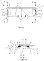
- FIGS. 1a-1c show a first embodiment with regard to a sensor unit 1 according to the invention.
- This sensor unit 1 has a carrier 2 .
- the carrier is as shown in the top view of the Fig. 1a can be seen, symmetrical.
- the symmetrical design relates in particular to the ends 3 and 4 of the beam 2.
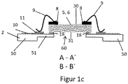
- FIG. 1b and 1c show sectional views according to section AA 'and BB' in alternative embodiments.
- a first resistance temperature sensor 5 and a second resistance temperature sensor 6 can also be seen.
- the resistance temperature sensors 5 and 6 are connected to the carrier 2 both structurally and electrically.
- the carrier 2 has two fastening lugs 51 in the area of the ends 3 and 4 in each case.
- the Fastening tabs 51 are, as in the sectional views of Fig. 1b and 1c can be seen, formed pointing to each other. There is no further carrier material between the two fastening tabs 51 .
- fastening tabs 51 have a smaller thickness and a smaller cross-section in comparison to the adjoining carrier sections 50 .
- recesses 55 can be seen. These recesses 55 are formed in such a way that the resistance temperature sensors 5 and 6 are connected to the fastening lugs 51 only on the undersides 31 at two sections 40 in each case.
- the resistance temperature sensors 5 and 6 on the top 30 can flow completely around all four end faces 32 .
- the undersides 31 can also largely be flowed around by a gas. Only the two attachment sections or sections 40 of the undersides 31 cannot be flowed around by gas.
- the sensors 5 and 6 are fixed to the carrier 2 at the fastening straps 51 .
- the resistance temperature sensors 5 and 6 each have contact pads 7 on the sections 40 of the undersides 31 .
- the resistance temperature sensors 5 and 6 can in turn be connected to contact pads 11 of the fastening straps 51 via these contact pads. This can be done according to the configuration of the Fig. 1b
- a further connection layer 12 can be formed between the contact pads 7 and 11 .
- the connecting layer 12 can be formed by a metal-containing sintering paste or by a conductive adhesive.
- the resistance temperature sensors 5 and 6 are preferably designed as flip-chip sensors.
- the resistance temperature sensors 5, 6 are formed in an imaginary storage of the sensor unit 1 on a storage surface in a plane that is formed above the carrier. In other words, the resistance temperature sensors 5 and 6 are formed entirely above a carrier 2 . This is not to be understood strictly mathematically and relates in particular to the area of the recess 60.
- the resistance temperature sensors 5 and 6 have bond pads 8 for this purpose. These are formed on the tops 30 .
- An electrical connection to the contact pads 11 formed in the area of the fastening tabs 51 can be established via wires 9 .
- a small adhesive layer 18 can be formed, for example, for structurally fixing the resistance temperature sensors 5 and 6 to the sensor 2 or to the fastening straps 51 .
- Electrical conductor tracks 10 can be seen on the upper side of the carrier 2 shown.
- the resistance temperature sensors 5 and 6 are electrically connected to these electrical conductor tracks. This is done by means of the contact pads 11.
- Contact areas 13 are located at the end of the conductor tracks 10. Leads to a monitoring and/or control unit can be attached to these contact areas 13.
- the battery pack 20 includes a Battery case 21.
- the battery case 21 has a case opening 22.
- a plurality of lithium-ion cells or battery cells 24 are formed in the battery housing 21 . These battery cells 24 are in turn located in a casing 23 .
- a sensor unit 1 is formed inside the housing 25 .
- This sensor unit 1 has two resistance temperature sensors 5 and 6 .
- the first resistance temperature sensor 5 is positioned in front of the housing opening 22, so that the resistance temperature sensor 5 in any gas flow 25 flowing from the housing interior 25 in the direction of the housing opening 22 (see Figure 2b ) is located.
- the second resistance temperature sensor 6, is designed at a distance from the housing opening 22, so that any gas stream 29 does not flow directly around it.
- the second resistance temperature sensor 6 is part of the common sensor unit 1.
- the two resistance temperature sensors 5 and 6 it would be possible for the two resistance temperature sensors 5 and 6 to be formed on sensor units that are separate from one another.
- the battery housing 21 includes, for example, a free volume inside the housing 25 of 0.05 m 3 .
- the free volume includes the areas within the battery housing 20 that are not occupied by condensed matter such as batteries, coolant, housing components, electronics or sensors. In the free volume there is gas under atmospheric pressure.
- the housing opening 22 connects the free volume with the exterior space 70 which is under atmospheric pressure.
- the housing opening 22 has an area of approximately 4 cm 2 .
- the sensor unit 1 is aligned in the housing interior 25 of the battery housing 21 in such a way that the sensitive surface of the resistance temperature sensor 5 opposes the gas flow 29 with its maximum surface.
- the temperature in the battery housing 21 is approximately 23°C.
- the resistance temperature sensors 5 and 6 are connected in series in the example shown and are both supplied with a constant current of, for example, 1-5 mA. This constant current heats the two resistance temperature sensors 5 and 6 to over 25° C., for example. This temperature is present at the resistance temperature sensors 5 and 6 when they are not located in a directed and therefore cooling gas flow 29 .
- gases within the battery housing 21 are released.
- the gases released generate an increase in pressure within the battery housing 21.
- the pressure building up in the battery housing 21 can increase by up to 10,000 pascals (100 mbar) within a few seconds. This increase in pressure corresponds to a volume increase of 5,000 cm 3 below normal pressure and temperature in the battery case 21 .
- the overpressure or the newly created volume of gas escapes via the housing opening 22 into the exterior space 70 within about 10 seconds.
- the volume flow density from the battery housing is 21,500 cm 3 /s. Consequently, the gas flow velocity in the area of the housing opening 22 is 1.25 m/s on average.
- This gas flow leads to a clearly detectable cooling of the resistance temperature sensor 5. Since the second resistance temperature sensor 6 is not or not directly in the gas flow 29, such a cooling of this resistance temperature sensor 6 cannot be detected.
- the electrical resistance of the resistance temperature sensor 5, which is operated at 3 mA, is 1,328.0 ohms (85° C.) in uncooled air. As the pressure in the battery case 21 increases, the resistance drops to 1320.4 ohms. This is due to the cooling gas flow 29 . The change in resistance corresponds to a decrease in temperature of the resistance temperature sensor 5 of 2 Kelvin.
- the electrical resistance of the resistance temperature sensor 6, which is not in the gas stream 29, is unchanged at 1,328.0 ohms during the thermal runaway.
- the resistance values of the two resistance temperature sensors 5 and 6 can be read out continuously by a control unit which is arranged outside the battery block 20, in particular outside the superordinate battery unit. If the control unit registers a change in resistance of the resistance temperature sensor 5 of >1 ohm within 3 seconds and the resistance of the resistance temperature sensor 6 remains almost unchanged, an alarm is activated, for example. This shows that pressure changes of 500 - 10,000 pascals in a battery case 21 can be demonstrated very precisely and that measures to warn or switch off the battery pack 20 can be initiated with this measurement signal.
- a further example is based on the fact that a pressure increase in the battery housing 21 caused by previous damage to a battery cell 24, in particular a lithium-ion battery cell, is only 2000 pascals. This pressure increase corresponds to a volume increase of 1,000 cm 3 under atmospheric pressure in the battery case 21 . The excess pressure or the newly created volume of gas escapes via the housing opening 22 into the exterior 70 within 10 seconds.
- the volume flow density from the battery housing 21 is 100 cm 3 /s. Consequently, the gas flow velocity in the area of the housing opening 22 is 0.25 m/s on average. This gas flow leads to a reliably demonstrable cooling of the resistance temperature sensor 5.
- the electrical resistance of the resistance temperature sensor 5, which is operated at 3 mA, is 1,328 ohms (85° C.) in uncooled air. As the pressure in the battery case 21 increases, the resistance drops to 1324.6 ohms. This is due to the cooling gas flow 29 . The change in resistance corresponds to a decrease in temperature of the resistance temperature sensor 5 by 0.9 Kelvin.
- the electrical resistance of the resistance temperature sensor 6 is unchanged at 1,328.0 ohms during the thermal runaway. It is thus shown that even small increases in pressure of 2,000 pascals in the battery housing 21, such as those that occur in the preliminary phase of thermal runaway, can be detected.
- the basic procedure corresponds to application examples 1 and 2, with the difference that the temperature in the battery housing 21 is approximately 70°C.
- the two resistance temperature sensors 5 and 6 are both subjected to a constant current of, for example, 20 mA. This constant current heats them both up Resistance temperature sensors 5 and 6 to 161.1 ° C each, provided they are not located in a directed and thus cooling gas flow 29.
- the resistance of the two resistance temperature sensors 5 and 6 is 1,614.6 ohms.
- a temperature reduction of 2 Kelvin of the resistance temperature sensor 5 in the gas stream 29 leads to a change in resistance to 1,607.2 ohms.
- This application example shows that precise temperature differences between two resistance temperature sensors 5 and 6 can be detected even at temperatures of 70° C. using a sensor unit 1 according to the invention.
- FIGS Figures 3a and 3b A further embodiment with regard to a sensor unit 1 according to the invention is shown in FIGS Figures 3a and 3b shown.
- the Figure 3a shows a plan view of the sensor unit according to the invention 1.
- a section AA' is shown in Figure 3b.
- only one resistance temperature sensor 5 is formed on the carrier 2 .
- This resistance temperature sensor 5 is positioned on fastening tabs 51 and fastened there to the carrier.
- the connection of the resistance temperature sensor 5 is as already in connection with Fig. 1b was presented and explained.
- the carrier 2 of Figure 3a again has a recess 55 so that a connection to a free space 60 can also be produced.
- the resistance temperature sensor 5 is designed as a flip chip sensor.
- Two electrical conductor tracks 10 are formed on the upper side of the carrier 2, to which the resistance temperature sensor 5 is electrically connected.
- the electrical conductor tracks 10 have contact areas 13 at the ends, which are used for contacting the resistance temperature sensor 5 and other connection wires.
- a sensor unit 1 such as those in the Figures 3a and 3b is shown.
- the control signals from the various resistance temperature sensors can be correlated with one another and examined with regard to stored threshold values.
- the amplification of the difference between the threshold value and the current value of the resistance temperature sensor also enables the resolution to be increased here.
- a detected difference signal allows a so-called zero-point detection for all exemplary embodiments. As soon as this difference is zero, the threshold value has already been reached. Sign changes can be detected particularly easily.
Landscapes
- Engineering & Computer Science (AREA)
- Power Engineering (AREA)
- Sustainable Development (AREA)
- Mechanical Engineering (AREA)
- Electrochemistry (AREA)
- General Chemical & Material Sciences (AREA)
- Chemical Kinetics & Catalysis (AREA)
- Life Sciences & Earth Sciences (AREA)
- Chemical & Material Sciences (AREA)
- Sustainable Energy (AREA)
- Transportation (AREA)
- Manufacturing & Machinery (AREA)
- Physics & Mathematics (AREA)
- Fluid Mechanics (AREA)
- General Physics & Mathematics (AREA)
- Secondary Cells (AREA)
Priority Applications (2)
| Application Number | Priority Date | Filing Date | Title |
|---|---|---|---|
| EP21171467.0A EP4083580A1 (fr) | 2021-04-30 | 2021-04-30 | Unité de capteur permettant de détecter des flux de gaz dans un bloc batterie ou dans une unité de batterie, bloc batterie, unité de batterie et procédé de détection du flux de gaz dans un bloc batterie ou dans une unité de batterie |
| PCT/EP2022/060658 WO2022229012A1 (fr) | 2021-04-30 | 2022-04-22 | Unité de détection pour flux de gaz dans un bloc-batterie ou dans une unité de batterie, bloc-batterie, unité de batterie et procédé de détection de flux de gaz dans un bloc-batterie ou dans une unité de batterie |
Applications Claiming Priority (1)
| Application Number | Priority Date | Filing Date | Title |
|---|---|---|---|
| EP21171467.0A EP4083580A1 (fr) | 2021-04-30 | 2021-04-30 | Unité de capteur permettant de détecter des flux de gaz dans un bloc batterie ou dans une unité de batterie, bloc batterie, unité de batterie et procédé de détection du flux de gaz dans un bloc batterie ou dans une unité de batterie |
Publications (1)
| Publication Number | Publication Date |
|---|---|
| EP4083580A1 true EP4083580A1 (fr) | 2022-11-02 |
Family
ID=75746417
Family Applications (1)
| Application Number | Title | Priority Date | Filing Date |
|---|---|---|---|
| EP21171467.0A Withdrawn EP4083580A1 (fr) | 2021-04-30 | 2021-04-30 | Unité de capteur permettant de détecter des flux de gaz dans un bloc batterie ou dans une unité de batterie, bloc batterie, unité de batterie et procédé de détection du flux de gaz dans un bloc batterie ou dans une unité de batterie |
Country Status (2)
| Country | Link |
|---|---|
| EP (1) | EP4083580A1 (fr) |
| WO (1) | WO2022229012A1 (fr) |
Families Citing this family (1)
| Publication number | Priority date | Publication date | Assignee | Title |
|---|---|---|---|---|
| EP3961170A1 (fr) * | 2020-08-27 | 2022-03-02 | Heraeus Nexensos GmbH | Capteur de température et procédé de fabrication d'un tel capteur de température |
Citations (9)
| Publication number | Priority date | Publication date | Assignee | Title |
|---|---|---|---|---|
| US20080264166A1 (en) * | 2005-10-24 | 2008-10-30 | Heraeus Sensor Technology Gmbh | Flow sensor element and its self-cleaning |
| EP2358432A1 (fr) | 2008-10-23 | 2011-08-24 | Cardiac Pacemakers, Inc. | Systèmes et procédés pour détecter des changements de configuration de dispositifs médicaux implantables affectant la sûreté conditionnelle d une irm |
| US20140241394A1 (en) * | 2013-02-25 | 2014-08-28 | The Boeing Company | Analysis of rechargeable batteries |
| EP2797158A1 (fr) | 2012-02-08 | 2014-10-29 | Hitachi, Ltd. | Système de pile |
| US20150122050A1 (en) * | 2012-04-06 | 2015-05-07 | Hitachi Automotive Systems, Ltd. | Flow sensor |
| US20190379030A1 (en) | 2018-06-06 | 2019-12-12 | Samsung Sdi Co., Ltd. | Battery system configured to detect abnormal battery system conditions and method of the same |
| CN110635182A (zh) * | 2019-09-06 | 2019-12-31 | Oppo广东移动通信有限公司 | 电池热失控的预警方法和装置、电子设备、存储介质 |
| EP3300162B1 (fr) | 2015-09-14 | 2020-01-29 | LG Chem, Ltd. | Système et procédé de détection de gonflement de batterie |
| KR102181521B1 (ko) | 2016-03-03 | 2020-11-20 | 주식회사 엘지화학 | 벤팅 가스의 배기 구조가 개선된 셀 모듈 어셈블리 |
Family Cites Families (1)
| Publication number | Priority date | Publication date | Assignee | Title |
|---|---|---|---|---|
| DE102014202635A1 (de) * | 2014-02-13 | 2015-08-13 | Robert Bosch Gmbh | Batteriezelle mit Stromunterbrechung bei Entgasung |
-
2021
- 2021-04-30 EP EP21171467.0A patent/EP4083580A1/fr not_active Withdrawn
-
2022
- 2022-04-22 WO PCT/EP2022/060658 patent/WO2022229012A1/fr not_active Ceased
Patent Citations (9)
| Publication number | Priority date | Publication date | Assignee | Title |
|---|---|---|---|---|
| US20080264166A1 (en) * | 2005-10-24 | 2008-10-30 | Heraeus Sensor Technology Gmbh | Flow sensor element and its self-cleaning |
| EP2358432A1 (fr) | 2008-10-23 | 2011-08-24 | Cardiac Pacemakers, Inc. | Systèmes et procédés pour détecter des changements de configuration de dispositifs médicaux implantables affectant la sûreté conditionnelle d une irm |
| EP2797158A1 (fr) | 2012-02-08 | 2014-10-29 | Hitachi, Ltd. | Système de pile |
| US20150122050A1 (en) * | 2012-04-06 | 2015-05-07 | Hitachi Automotive Systems, Ltd. | Flow sensor |
| US20140241394A1 (en) * | 2013-02-25 | 2014-08-28 | The Boeing Company | Analysis of rechargeable batteries |
| EP3300162B1 (fr) | 2015-09-14 | 2020-01-29 | LG Chem, Ltd. | Système et procédé de détection de gonflement de batterie |
| KR102181521B1 (ko) | 2016-03-03 | 2020-11-20 | 주식회사 엘지화학 | 벤팅 가스의 배기 구조가 개선된 셀 모듈 어셈블리 |
| US20190379030A1 (en) | 2018-06-06 | 2019-12-12 | Samsung Sdi Co., Ltd. | Battery system configured to detect abnormal battery system conditions and method of the same |
| CN110635182A (zh) * | 2019-09-06 | 2019-12-31 | Oppo广东移动通信有限公司 | 电池热失控的预警方法和装置、电子设备、存储介质 |
Also Published As
| Publication number | Publication date |
|---|---|
| WO2022229012A1 (fr) | 2022-11-03 |
Similar Documents
| Publication | Publication Date | Title |
|---|---|---|
| EP2542902B1 (fr) | Composant électronique, capteur de courant | |
| DE60028282T2 (de) | Leistungshalbleitermodul | |
| EP1030185B1 (fr) | Dispositif pour controler le courant dans un réseau de distribution d'énergie | |
| EP2550516B1 (fr) | Système d'accumulation d'énergie et unité de mesure de la température et de la tension d'un composant electrique/electronique | |
| DE102005059224B4 (de) | SiC-Halbleitervorrichtung und Herstellungsverfahren dafür | |
| DE102012211924B4 (de) | Halbleitermodul mit einem in einer Anschlusslasche integrierten Shunt-Widerstand und Verfahren zur Ermittlung eines durch einen Lastanschluss eines Halbleitermoduls fließenden Stromes | |
| DE10011233A1 (de) | Batterieeinheit | |
| DE112013005730T5 (de) | Temperatursensor | |
| WO2017102272A1 (fr) | Installation de mesure pour le contrôle fonctionnel de batteries rechargeables | |
| EP3615903B1 (fr) | Capteur de détection d'un profil de température spatial et procédé de fabrication d'une unité de détection | |
| DE3887849T2 (de) | Integrierte Schaltungspackung. | |
| DE202009002852U1 (de) | Sicherungsanordnung | |
| DE102011004353B4 (de) | Leiterplatte mit einer Überwachungselektronik zur Überwachung von Batteriezellen, sowie damit ausgestatteter elektrischer Energiespeicher | |
| DE102014116451A1 (de) | Sensoranordnung, Energiesystem und Verfahren | |
| DE3438764A1 (de) | Thermoelektrischer detektor | |
| WO2022229012A1 (fr) | Unité de détection pour flux de gaz dans un bloc-batterie ou dans une unité de batterie, bloc-batterie, unité de batterie et procédé de détection de flux de gaz dans un bloc-batterie ou dans une unité de batterie | |
| DE102014115588A1 (de) | Sicherungseinrichtung und Verfahren zum Herstellen einer Sicherungseinrichtung | |
| EP2732488B1 (fr) | Dispositif servant à guider un courant électrique | |
| EP4073870B1 (fr) | Batterie ayant un dispositif de mesure de température | |
| EP2737327B1 (fr) | Circuit pour conduire un courant électrique | |
| EP4055358B1 (fr) | Élément capteur pour détecter la température d'un objet et méthode pour evaluer la qualité de mesure d'un tel élément capteur | |
| DE102020203959A1 (de) | Temperaturmessanordnung und Verfahren zur Messung der Temperatur von einer oder mehreren Zellen | |
| DE102017010404B4 (de) | Vibrationswandler | |
| DE102009037111B4 (de) | Kompakter Infrarotlichtdetektor und Verfahren zur Herstellung desselben | |
| WO2023052066A1 (fr) | Batterie pourvue d'un capteur de température et véhicule automobile |
Legal Events
| Date | Code | Title | Description |
|---|---|---|---|
| PUAI | Public reference made under article 153(3) epc to a published international application that has entered the european phase |
Free format text: ORIGINAL CODE: 0009012 |
|
| STAA | Information on the status of an ep patent application or granted ep patent |
Free format text: STATUS: THE APPLICATION HAS BEEN PUBLISHED |
|
| AK | Designated contracting states |
Kind code of ref document: A1 Designated state(s): AL AT BE BG CH CY CZ DE DK EE ES FI FR GB GR HR HU IE IS IT LI LT LU LV MC MK MT NL NO PL PT RO RS SE SI SK SM TR |
|
| STAA | Information on the status of an ep patent application or granted ep patent |
Free format text: STATUS: REQUEST FOR EXAMINATION WAS MADE |
|
| 17P | Request for examination filed |
Effective date: 20230210 |
|
| RBV | Designated contracting states (corrected) |
Designated state(s): AL AT BE BG CH CY CZ DE DK EE ES FI FR GB GR HR HU IE IS IT LI LT LU LV MC MK MT NL NO PL PT RO RS SE SI SK SM TR |
|
| RAP3 | Party data changed (applicant data changed or rights of an application transferred) |
Owner name: YAGEO NEXENSOS GMBH |
|
| STAA | Information on the status of an ep patent application or granted ep patent |
Free format text: STATUS: EXAMINATION IS IN PROGRESS |
|
| 17Q | First examination report despatched |
Effective date: 20240109 |
|
| STAA | Information on the status of an ep patent application or granted ep patent |
Free format text: STATUS: THE APPLICATION IS DEEMED TO BE WITHDRAWN |
|
| 18D | Application deemed to be withdrawn |
Effective date: 20240511 |