EP4083590B1 - Sensoranordnung, kraftmessvorrichtung und verfahren sowie baumaschine - Google Patents
Sensoranordnung, kraftmessvorrichtung und verfahren sowie baumaschine Download PDFInfo
- Publication number
- EP4083590B1 EP4083590B1 EP20908288.2A EP20908288A EP4083590B1 EP 4083590 B1 EP4083590 B1 EP 4083590B1 EP 20908288 A EP20908288 A EP 20908288A EP 4083590 B1 EP4083590 B1 EP 4083590B1
- Authority
- EP
- European Patent Office
- Prior art keywords
- sensing unit
- connecting part
- initial gap
- measurement result
- peripheral portion
- Prior art date
- Legal status (The legal status is an assumption and is not a legal conclusion. Google has not performed a legal analysis and makes no representation as to the accuracy of the status listed.)
- Active
Links
Images


Classifications
-
- G—PHYSICS
- G01—MEASURING; TESTING
- G01L—MEASURING FORCE, STRESS, TORQUE, WORK, MECHANICAL POWER, MECHANICAL EFFICIENCY, OR FLUID PRESSURE
- G01L5/00—Apparatus for, or methods of, measuring force, work, mechanical power, or torque, specially adapted for specific purposes
- G01L5/0061—Force sensors associated with industrial machines or actuators
-
- G—PHYSICS
- G01—MEASURING; TESTING
- G01L—MEASURING FORCE, STRESS, TORQUE, WORK, MECHANICAL POWER, MECHANICAL EFFICIENCY, OR FLUID PRESSURE
- G01L1/00—Measuring force or stress, in general
- G01L1/20—Measuring force or stress, in general by measuring variations in ohmic resistance of solid materials or of electrically-conductive fluids; by making use of electrokinetic cells, i.e. liquid-containing cells wherein an electrical potential is produced or varied upon the application of stress
- G01L1/22—Measuring force or stress, in general by measuring variations in ohmic resistance of solid materials or of electrically-conductive fluids; by making use of electrokinetic cells, i.e. liquid-containing cells wherein an electrical potential is produced or varied upon the application of stress using resistance strain gauges
- G01L1/2206—Special supports with preselected places to mount the resistance strain gauges; Mounting of supports
- G01L1/2218—Special supports with preselected places to mount the resistance strain gauges; Mounting of supports the supports being of the column type, e.g. cylindric, adapted for measuring a force along a single direction
-
- G—PHYSICS
- G01—MEASURING; TESTING
- G01L—MEASURING FORCE, STRESS, TORQUE, WORK, MECHANICAL POWER, MECHANICAL EFFICIENCY, OR FLUID PRESSURE
- G01L1/00—Measuring force or stress, in general
- G01L1/20—Measuring force or stress, in general by measuring variations in ohmic resistance of solid materials or of electrically-conductive fluids; by making use of electrokinetic cells, i.e. liquid-containing cells wherein an electrical potential is produced or varied upon the application of stress
- G01L1/22—Measuring force or stress, in general by measuring variations in ohmic resistance of solid materials or of electrically-conductive fluids; by making use of electrokinetic cells, i.e. liquid-containing cells wherein an electrical potential is produced or varied upon the application of stress using resistance strain gauges
- G01L1/2206—Special supports with preselected places to mount the resistance strain gauges; Mounting of supports
- G01L1/2231—Special supports with preselected places to mount the resistance strain gauges; Mounting of supports the supports being disc- or ring-shaped, adapted for measuring a force along a single direction
-
- G—PHYSICS
- G01—MEASURING; TESTING
- G01L—MEASURING FORCE, STRESS, TORQUE, WORK, MECHANICAL POWER, MECHANICAL EFFICIENCY, OR FLUID PRESSURE
- G01L1/00—Measuring force or stress, in general
- G01L1/20—Measuring force or stress, in general by measuring variations in ohmic resistance of solid materials or of electrically-conductive fluids; by making use of electrokinetic cells, i.e. liquid-containing cells wherein an electrical potential is produced or varied upon the application of stress
- G01L1/22—Measuring force or stress, in general by measuring variations in ohmic resistance of solid materials or of electrically-conductive fluids; by making use of electrokinetic cells, i.e. liquid-containing cells wherein an electrical potential is produced or varied upon the application of stress using resistance strain gauges
- G01L1/2268—Arrangements for correcting or for compensating unwanted effects
Definitions
- the present disclosure relates to the detection of construction equipment, in particular to a sensor assembly, a force detection device and method, and construction machinery.
- Construction equipment such as cranes, usually have legs extend around them to provide support, in order to improve overturning resistance.
- the magnitude of the supporting force directly reflects the current supporting safety situation of a crane. For example, when the supporting forces of two adjacent legs are close to zero (a "non-supporting leg” state), it indicates that the crane is at a risk of instability. Therefore, it is highly necessary to accurately monitor the supporting forces of the legs.
- usually wide-range sensors are used in view of the high supporting reaction forces, but such wide-range sensors can't meet the requirement for measurement accuracy under low loads.
- CN 85 104 807 A discloses a multi-range force sensor and CN 10 981 3470 A discloses a highsensitivity and wide-range pressure sensor.
- An object of the present disclosure is to provide a sensor assembly according to claim 1 to realize accurate detection.
- the present disclosure further provides a force detection method according to claim 11 for detecting an acting force borne on a force bearing device by using a sensor assembly according to any one of claims 1 to 8.
- the present disclosure provides a sensor assembly, which comprises a connecting part 100 used for connecting a base to be tested and a bearing part 200 used for bearing, wherein the bearing part 200 is connected to the connecting part 100, the bearing part 200 comprises at least two sensing units with different measuring ranges, and the at least two sensing units are arranged to have different initial gaps from the connecting part 100, so that corresponding initial gaps are eliminated when a load applied to the bearing part 200 reaches different extents.
- Sensing units with different measuring ranges can provide different measurement accuracies under different loads.
- a sensing unit with a smaller measuring range can provide higher measurement accuracy when it is used to detect smaller loads, while a sensing unit with a greater measuring range can provide higher measurement accuracy when it is used to detect greater loads.
- different initial gaps are eliminated by applying the load to different extents, so that the sensing units with different measuring ranges can provide detection feedback in respective working conditions in which the units have the highest measurement precision, thereby the accuracy of detection results is ensured.
- the at least two sensing units comprise a first sensing unit 210 and a second sensing unit 220
- the measuring range of the first sensing unit 210 is greater than that of the second sensing unit 220
- the first sensing unit 210 has a first initial gap b1 from the connecting part 100
- the second sensing unit 220 has a second initial gap b2 from the connecting part 100.
- appropriate detection modes can be set as required, so as to output a detection result via different sensing units a combination of the sensing units under different conditions.
- the detection is carried out with a sensing unit with a smaller measuring range under lower loads, while the detection is carried out with a sensing unit with a greater measuring range under greater loads.
- the sensor assembly comprises an output unit for outputting a measurement signal, which is configured to: output a measurement result from the second sensing unit 220 when the load applied to the bearing part 200 is lower than a first predetermined value; or output a measurement result from the first sensing unit 210 or the sum of a measurement result from the first sensing unit 210 and a measurement result from the second sensing unit 220 when the load applied to the bearing part 200 is higher than the first predetermined value, the first predetermined value is 5-10% of the total measuring range of the sensor assembly.
- the output unit is configured to output a measurement result from the second sensing unit 220 before the smaller one of the first initial gap b1 and the second initial gap b2 is eliminated; or output a measurement result from the first sensing unit 210 or the sum of a measurement result from the first sensing unit 210 and a measurement result from the second sensing unit 220 after the smaller one of the first gap b1 and the second initial gap b2 is eliminated.
- the first predetermined value is used as a threshold, the load is low when it is lower than the first predetermined value, and the measurement result from the second sensing unit 220 is outputted to achieve higher accuracy; the load is high when it is higher than the first predetermined value, and the measurement accuracy of the first sensing unit 210 with a higher measuring range is higher in that case. Therefore, the outputted measurement result shall include the detection result from the first sensing unit 210.
- a load equal to the first predetermined value may correspond to a maximum value in the measuring range of the second sensing unit 220.
- the elimination of the smaller one of the first initial gap b1 and the second initial gap b2 may be used as a threshold for introducing the measurement result from the first sensing unit 210.
- the elimination of the smaller one of the first initial gap b1 and the second initial gap b2 may correspond to a maximum value in the measuring range of the second sensing unit 220.
- the first predetermined value and the elimination of the smaller one of the first initial gap b1 and the second initial gap b2 may be used in combination as a threshold for introducing the measurement result from the first sensing unit 210. That is to say, when the first initial gap b1 is eliminated, the load applied to the bearing part 200 just reaches the first predetermined value.
- the output unit can realize the output of the measurement result under different conditions by means of appropriate circuit control.
- the specific circuit structure is a existing arrangement in the art and will not be further detailed here.
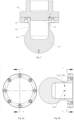
- the first sensing unit 210 may have a columnar sensing structure and comprise a columnar body 211 and a plurality of first strain gauges 212 that are arranged around the circumference of the columnar body 211;
- the second sensing unit 220 has a spoke-type sensing structure and comprises an outer rim 221, a hub 222, and spokes 221 arranged between the outer rim 222 and the hub 223, wherein the hub 222 has a top surface protruding from the spokes 223 and a blind hole 2221 that is arranged axially and open toward the connecting part 100, the spokes 223 are provided with second strain gauges 224 on a side, the columnar body 211 is fitted in the blind hole 2221, and the connecting part 100 is provided with a first positioning hole 110 for inserting the columnar body 221.
- Second strain gauges 224 may be provided in the central areas of the two sides of the spokes 223.
- a plurality of second strain gauges 224 may be provided on each side, and adjacent second strain gauges 224 may be bonded in directions perpendicular to each other, for example, at ⁇ 45 degrees from the horizontal direction (the cross-sectional direction of the hub 222) respectively.
- Protective films may be applied between the spokes 223, so as to seal the areas where the second strain gauges 224 are mounted.
- the bearing part 200 By fitting the columnar body 211 into the first positioning hole 110, the bearing part 200 can be prevented from being offset and deformed under high lateral load (a load deviating from the center line of the columnar body 211), thereby the second sensing unit 220 with a smaller measuring range can be protected against damage.
- the connecting part 100 has a first surface opposite to the bottom surface of the columnar body 211, a second surface opposite to the bottom surface of the outer rim 221, and a third surface opposite to the bottom surface of the hub 222, the first initial gap b1 is formed between the bottom surface of the columnar body 211 and the first surface, the second initial gap b2 is formed between the bottom surface of the outer rim 221 and the second surface, an anti-overload gap b3 is formed between the bottom surface of the hub 223 and the third surface, the first initial gap b1 is smaller than the second initial gap b2 (i.e., the first initial gap b1 is smaller), and the second initial gap b2 is smaller than the anti-overload gap b3.
- a first elastic gasket 225 is arranged between the outer rim 221 and the connecting part 100.
- the connecting part 100 may be provided with a first elastic gasket groove 150 for receiving the first elastic gasket 225.
- first elastic gasket 225 When the first elastic gasket 225 is exposed from the first elastic gasket groove 150, it can provide elasticity to decrease the overall rigidity of the second sensing unit 220 and the first elastic gasket 225 (i.e., the overall rigidity is smaller than the sum of the maximum rigidity of the first elastic gasket 225 and the rigidity of the second sensing unit 220 and is adjustable); when the first elastic gasket 225 is compressed to be fully accommodated in the first elastic gasket groove 150, the second sensing unit 220 is in direct contact with the connecting part 100, and the rigidity doesn't change anymore.
- the second sensing unit 220 with a smaller measuring range always has a force transfer relationship with the connecting part 100 via the first elastic gasket 225 (however, the second initial gap between the second sensing unit 220 and the connecting part 100 is kept when the load is very low, i.e., the second sensing unit 220 and the connecting part 100 don't contact with each other directly), so that the second sensing unit 220 can sense the load from the beginning when the load is applied, in order to achieve higher measurement accuracy under low loads.
- the bearing part 200 bears low acting force (e.g., lower than a first preset value)
- the first sensing unit 210 doesn't contact with the connecting part 100
- the second sensing unit 220 contacts with the connecting part 100 via the first elastic gasket 225. Therefore, the load is fully transferred by the connecting part 100 via the first elastic gasket 225 to the outer rim 221, the supporting reaction force F is essentially equal to the load F3 borne on the outer rim 221, and may be detected by the second strain gauges 224.
- the load is low, a detection result with higher accuracy can be provided by means of the second sensing unit 220 with a smaller measuring range. This state corresponds to a first measuring range stage of the sensor assembly.
- the second sensing unit 220 contacts with the connecting part 100 via the first elastic gasket 225, and the first sensing unit 210 contacts with the connecting part 100 via the columnar body 211; at that point, the first sensing unit 210 and the second sensing unit 220 bear the load jointly, and the supporting reaction force F is essentially equal to the sum of the load F3 borne on the outer rim 221 and the load F1 borne on the columnar body 211.
- a detection result of the load with high accuracy can be provided by the first sensing unit 210 and the second sensing unit 220 respectively, the measurement result is provided by the first sensing unit 210 and the second sensing unit 220 jointly, and is the sum of a measured value from the first sensing unit 210 and a measured value from the second sensing unit 220.
- This state corresponds to a second measuring range stage of the sensor assembly.
- the first elastic gasket 225 doesn't provide a rigidity reduction effect anymore, the second sensing unit 220 directly contacts with the connecting part 100 via the outer rim 221, and the first sensing unit 210 contacts with the connecting part 100 via the columnar body 211; at that point, the first sensing unit 210 and the second sensing unit 220 bear the load jointly, and the supporting reaction force F is essentially equal to the sum of the load F3 borne on the outer rim 221 and the load F1 borne on the columnar body 211.
- a detection result of the load with high accuracy can be provided by the first sensing unit 210 and the second sensing unit 220 respectively, the measurement result is provided by the first sensing unit 210 and the second sensing unit 220 jointly, and is the sum of a measured value from the first sensing unit 210 and a measured value from the second sensing unit 220.
- This state corresponds to a third measuring range stage of the sensor assembly.
- the connecting part 100 e.g., an anti-overload boss 160 arranged in the central portion
- the spokes 222 with the second strain gauges 224 are protected against damage by excessive load. This state corresponds to an overload protection stage of the sensor assembly.
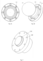
- the bearing part 200 comprises a cylindrical body 230 corresponding to a central portion of the connecting part 100 and a peripheral portion 240 corresponding to a peripheral portion of the connecting part 100, the cylindrical body 230 and the peripheral portion 240 are formed integrally, an inner wall of the cylindrical body 230 is provided with the first strain gauges 212 to form the first sensing unit 210, and the peripheral portion 240 is provided with the second strain gauges 224 to form the second sensing unit 220.
- the initial gaps may be formed according to the specific structural design. Specifically, two ends of the cylindrical body 230 protrude from the end faces of the peripheral portion 240, the connecting part 100 comprises a fourth surface opposite to an end face of the cylindrical body 230 and a fifth surface opposite to an end face of the peripheral portion 240, the first initial gap b1 is formed between the end face of the cylindrical body 230 and the fourth surface, and the second initial gap b2 is formed between the end face of the peripheral portion 240 and the fifth surface.
- first strain gauges 212 comprise longitudinal strain gauges 2121 arranged in the extension direction of the cylindrical body 230; preferably, the first strain gauges 212 further comprise transverse strain gauges 2122 arranged perpendicular to the extension direction of the cylindrical body 230, in order to improve the sensitivity of detection.
- two types of sensor assemblies may be used.
- the cylindrical body 230 comprises a cylindrical structure 260
- the peripheral portion 240 comprises an annular portion 270 around the cylindrical structure 260 and a plate portion 280 arranged between the annular portion 270 and the cylindrical structure 260
- the first strain gauges 212 are arranged on an inner wall of the cylindrical structure 260
- the second strain gauges 224 are arranged on the sides of the plate portion 280, wherein the first initial gap b1 is formed between the cylindrical structure 260 and the connecting part 100, the second initial gap b2 is formed between the plate portion 280 and the connecting part 100 and is equal to zero, i.e., the second initial gap b2 is smaller.
- the connecting part 100 has a positioning boss 130 for inserting into a hollow portion of the cylindrical structure 260 to prevent the bearing part 200 from being offset and deformed owing to a high lateral load (i.e., a load deviating from the center line of the cylindrical structure 260), thereby the second sensing unit 220 with a smaller measuring range is protected against damage.
- a high lateral load i.e., a load deviating from the center line of the cylindrical structure 260
- both the cylindrical structure 260 and the annular portion 270 may have an annular cross section, the annular portion 270 and the cylindrical structure 260 are arranged coaxially, the second strain gauges 224 may be arranged in pairs, and each pair of second strain gauges 224 are arranged near the two sides of the annular plate portion 280 respectively in the radial direction respectively (i.e., the pair of second strain gauges 224 are arranged in the radial direction of the plate portion 280, one second strain gauge 224 in the pair is arranged near the inner side of the plate portion 280 in the radial direction, while the other second strain gauge 224 in the pair is arranged near the outer side of the plate portion 280 in the radial direction), so as to measure the transverse strain of the cylindrical body 230.
- the second strain gauges 224 in the same pair may be configured to detect loads that are similar in magnitude but opposite to each other in direction during the detection.
- the bearing part 200 bears low acting force (e.g., lower than a first preset value)
- the first initial gap b1 is not eliminated, the first sensing unit 210 contacts with the connecting part 100, and the second sensing unit 220 doesn't contact with the connecting part 100 directly; therefore, the load is fully transferred by the connecting part 100 to the cylindrical structure 260 and is borne on the cylindrical structure 260, the annular portion 270 and the plate portion 280 that are integrally formed; at that point, since the load is low, the measurement result from the second sensing unit 220 with a smaller measuring range has higher accuracy; therefore, the detection may be carried out with the second strain gauges 224, so as to provide a detection result with higher accuracy.
- This state corresponds to a first measuring range stage of the sensor assembly.
- the load is fully transferred by the connecting part 100 to the cylindrical structure 260 and the annular portion 270, and is borne on the cylindrical structure 260, the annular portion 270 and the plate portion 280 that are integrally formed; at that point, since the load is high, the measurement result from the first sensing unit 210 with a greater measuring range has higher accuracy, while the second sensing unit 220 with a smaller measuring range only bears the load together with the first sensing unit 210 but is not suitable for providing a measurement result since the measured value from the second sensing unit 220 is not accurate anymore. Therefore, the detection may be carried out with the first strain gauge 212 so as to provide a detection result with higher accuracy. This state corresponds to a second measuring range stage of the sensor assembly.
- a predetermined value e.g., higher than the first preset value
- the peripheral portion 240 is in a flange form and connected to the cylindrical body 230 via an annular plate, and the second strain gauges 224 are arranged on the annular plate.
- a second elastic gasket 241 is arranged between the peripheral portion 240 and the connecting part 100 to reduce the overall rigidity of the second sensing unit 220 and the second elastic gasket 241 as an integral structure.
- An accommodating groove may be arranged in the connecting part 100 and/or the peripheral portion 240 to facilitate the arrangement of the second elastic gasket 241.
- the first initial gap b1 is smaller than the second initial gap b2.
- the connecting part 100 has a positioning hole 120 for inserting the cylindrical body 230 to prevent the bearing part 200 from being offset and deformed owing to a high lateral load (i.e., a load deviating from the center line of the cylindrical body 230), thereby the second sensing unit 220 with a smaller measuring range is protected against damage.
- a high lateral load i.e., a load deviating from the center line of the cylindrical body 230
- the acting force borne on the bearing part 200 is low (e.g., lower than a first preset value)
- the first sensing unit 210 doesn't contact with the connecting part 100
- the second sensing unit 220 contacts with the connecting part 100 via the second elastic gasket 241; therefore, the load is fully transferred by the connecting part 100 to the peripheral portion 240, and is borne on the cylindrical body 230 and the peripheral portion 240 that are formed integrally.
- the supporting reaction force F is essentially equal to the load F 1 borne on the peripheral portion 240, thereby can be detected by means of the second strain gauges 224.
- the load since the load is low, a detection result with higher accuracy can be provided by means of the second sensing unit 220 with a smaller measuring range. This state corresponds to a first measuring range stage of the sensor assembly.
- the second sensing unit 220 contacts with the connecting part 100 via the second elastic gasket 241, the first sensing unit 210 contacts with the connecting part 100 via the cylindrical body 230, and the load is borne on the cylindrical body 230 and the peripheral portion 240 that are formed integrally; at that point, since the low is high, the measurement result from the first sensing unit 210 with a greater measuring range has higher accuracy, while the second sensing unit 220 with a smaller measuring range only bears the load together with the first sensing unit 210 but is not suitable for providing a measurement result since the measured value from the second sensing unit 220 is not accurate anymore. Therefore, the detection may be carried out with the first strain gauges 212 so as to provide a detection result with higher accuracy. This state corresponds to a second measuring range stage of the sensor assembly.
- a predetermined value e.g., higher than the first preset value
- the second elastic gasket 241 doesn't provides a rigidity reduction effect anymore.
- the load is fully transferred by the connecting part 100 directly to the cylindrical body 230 and the peripheral portion 240, and is borne on the cylindrical body 230 and the peripheral portion 240 that are formed integrally; at that point, since the low is high, the measurement result from the first sensing unit 210 with a greater measuring range has higher accuracy, while the second sensing unit 220 with a smaller measuring range only bears the load together with the first sensing unit 210 but is not suitable for providing a measurement result since the measured value from the second sensing unit 220 is not accurate anymore. Therefore, the detection may be carried out with the first strain gauges 212 so as to provide a detection result with higher accuracy. This state corresponds to a second measuring range stage of the sensor assembly.
- first mounting holes 140 and second mounting holes 271 may be arranged in the connecting part 100 and the bearing part 200 respectively, and the connecting part 100 may be connected to the bearing part 200 by fasteners inserted through the first mounting holes 140 and the second mounting holes 271.
- the sensor assembly comprises an axis and is configured in a symmetric structure in relation to the axis, and the bearing part 200 has a surface for bearing force, wherein the surface is a spherical surface 250 and the axis passes through a center of sphere of the spherical surface.
- the bearing part 100 is configured to bear the load in the axial direction as far as possible.
- a spherical surface 250 may be arranged at the end of the columnar body 211 and the cylindrical body 230 away from the connecting part 100, as in the embodiment shown in Figs. 1-6c and 10-12d , or a bearing bulb 261 may be arranged at the end of the cylindrical structure 260 to form a spherical surface 250, as in the embodiment shown in Figs. 7-9 .
- the present disclosure provides a force detection device, which comprises force bearing device 300 and the sensor assembly according to the present disclosure. As shown in Figs. 1 and 2 , the connecting part 100 is mounted to a force bearing end of the force bearing device 300. With the sensor assembly provided by the present disclosure, the acting force borne on the force bearing device 300 can be detected more accurately.
- the present disclosure further provides construction machinery, which comprises the force detection device according to the present disclosure.
- the force detection device in the present disclosure may be used in construction machinery where the bearing force is to be detected.
- the construction machinery may comprise legs, and the force bearing devices 300 may be leg cylinders of the legs.
- the connecting part 100 may be mounted to an extended end of the piston rod 310 of each leg cylinder.
- the present disclosure provides a force detection method for detecting an acting force borne on a force bearing device 300 by using a bearing part 200 including at least two sensing units, which comprises: arranging the at least two sensing units to have different initial gaps from a connecting part 100 connected to the force bearing device 300, so as to eliminate corresponding initial gaps when the acting force reaches different extents, thereby detect the acting force with different sensing units.
- the force bearing device may be a bulb-type cylinder 300, e.g., a leg cylinder in construction machinery, and the measured acting force is the supporting reaction force of the leg.
- the piston rods 310 extends out and contacts with the leg plate, the stress surface of the bearing part 200 is subjected to the supporting reaction force.
- the at least two sensing units comprise a first sensing unit 210 and a second sensing unit 220, wherein the first sensing unit 210 has a first initial gap b1 from the connecting part 100, the second sensing unit 220 has a second initial gap b2 from the connecting part 100, the first sensing unit 210 has a measuring range greater than that of the second sensing unit 220, and the method comprises:
- the first predetermined value is used as a threshold, the load is low when it is lower than the first predetermined value, and the measurement result from the second sensing unit 220 is outputted to achieve higher accuracy; the load is high when it is higher than the first predetermined value, and the measurement accuracy of the first sensing unit 210 with a higher measuring range is higher in that case. Therefore, the outputted measurement result shall include the detection result from the first sensing unit 210.
- a load equal to the first predetermined value may correspond to a maximum value in the measuring range of the second sensing unit 220.
- the elimination of the smaller one of the first initial gap b1 and the second initial gap b2 may be used as a threshold for introducing the measurement result from the first sensing unit 210.
- the elimination of the smaller one of the first initial gap b1 and the second initial gap b2 may correspond to a maximum value in the measuring range of the second sensing unit 220.
- the first predetermined value and the elimination of the smaller one of the first initial gap b1 and the second initial gap b2 may be used in combination as a threshold for introducing the measurement result from the first sensing unit 210. That is to say, when the first initial gap b1 is eliminated, the load applied to the bearing part 200 just reaches the first predetermined value.
- the specific detection mode may be determined according to the specific structures of the sensing units.
- the method provided by the present disclosure uses the sensor assembly provided by the present disclosure for the detection.
- the first sensing unit 210 has a columnar sensing structure and comprises a columnar body 211 and a plurality of first strain gauges 212 that are arranged around the circumference of the columnar body 211;
- the second sensing unit 220 has a spoke-type sensing structure and comprises an outer rim 221, a hub 222, and spokes 221 arranged between the outer rim 222 and the hub 223, the hub 222 has a top surface protruding from the spokes 223 and a blind hole 2221 that is arranged axially and open toward the connecting part 100, the spokes 224 are provided with second strain gauges 223 on a side, the columnar body 211 is fitted in the blind hole 2221, the connecting part 100 is provided with a first positioning hole 110 for inserting the columnar body 211, the connecting part 100 has a first surface opposite to the bottom surface of the columnar body 211, a second surface opposite to the bottom surface of the outer
- the bearing part 200 comprises a cylindrical body 230 corresponding to a central portion of the connecting part 100 and a peripheral portion 240 corresponding to a peripheral portion of the connecting part 100, the cylindrical body 230 and the peripheral portion 240 are formed integrally, an inner wall of the cylindrical body 230 is provided with first strain gauges 212 to form the first sensing unit 210, the peripheral portion 240 is provided with second strain gauges 224 to form the second sensing unit 220, two ends of the cylindrical body 230 protrude from the end faces of the peripheral portion 240, the connecting part 100 comprises a fourth surface opposite to an end face of the cylindrical body 230 and a fifth surface opposite to an end face of the peripheral portion 240, the first initial gap b1 is formed between the end face of the cylindrical body 230 and the fourth surface, the second initial gap b2 is formed between the end face of the peripheral portion 240 and the fifth surface, and the method comprises: using a measurement result from the second sensing unit
Landscapes
- Physics & Mathematics (AREA)
- General Physics & Mathematics (AREA)
- Chemical & Material Sciences (AREA)
- Analytical Chemistry (AREA)
- Force Measurement Appropriate To Specific Purposes (AREA)
Claims (14)
- Eine Sensoranordnung, die ein Verbindungsteil (100) zum Verbinden einer zu prüfenden Basis und ein Lagerteil (200) zum Lagern umfasst, wobei das Lagerteil (200) mit dem Verbindungsteil (100) verbunden ist, das Lagerteil (200) eine erste Sensoreinheit (210) und eine zweite Sensoreinheit (220) umfasst, wobei der Messbereich der ersten Sensoreinheit (210) größer ist als der der zweiten Sensoreinheit (220), dadurch gekennzeichnet, dass die erste Sensoreinheit (210) einen ersten Anfangsspalt b1 von dem Verbindungsteil (100) aufweist und die zweite Sensoreinheit (220) einen zweiten Anfangsspalt b2 von dem Verbindungsteil (100) aufweist, wobei der erste Anfangsspalt b1 kleiner ist als der zweite Anfangsspalt b2, so dass entsprechende Anfangsspalten eliminiert werden, wenn eine auf das Lagerteil (200) ausgeübte Last unterschiedliche Ausmaße erreicht, und die Sensoranordnung eine elastische Dichtung (225, 241) umfasst, die so angeordnet ist, dass: wenn die auf das Lagerteil (200) einwirkende Kraft kleiner als ein voreingestellter Wert ist, der erste Anfangsspalt b1 nicht eliminiert wird und die erste Sensoreinheit (210) das Verbindungsteil (100) nicht berührt und die zweite Sensoreinheit (220) mit dem Verbindungsteil (100) über die elastische Dichtung (225, 241) in Kontakt steht, undwenn die auf das Lagerteil (200) einwirkende Kraft einen vorbestimmten Wert erreicht, der höher als der voreingestellte Wert ist, wird der erste Anfangsspalt b1 eliminiert und die zweite Sensoreinheit (220) mit dem Verbindungsteil (100) über die elastische Dichtung (225, 241) in Kontakt steht,wobei die erste Sensoreinheit (210) eine säulenförmige Sensorstruktur aufweist und einen säulenförmigen Körper (211) umfasst, und die erste Sensoreinheit (210) mit dem Verbindungsteil (100) über den säulenförmigen Körper (211) in Kontakt steht, wenn die einwirkende Kraft den vorbestimmten Wert erreicht, wobei an diesem Punkt die erste Sensoreinheit (210) und die zweite Sensoreinheit (220) die Last gemeinsam tragen, oderwobei das Lagerteil (200) einen zylindrischen Körper (230), der einem zentralen Abschnitt des Verbindungsteils (100) entspricht, und einen peripheren Abschnitt (240), der einem peripheren Abschnitt des Verbindungsteils (100) entspricht, umfasst, wobei der zylindrische Körper (230) und der periphere Abschnitt (240) einstückig ausgebildet sind, wobei die erste Sensoreinheit (210) mit dem Verbindungsteil (100) über den zylindrischen Körper (230) in Kontakt steht, wenn die einwirkende Kraft den vorbestimmten Wert erreicht, und die Last auf dem zylindrischen Körper (230) und dem peripheren Abschnitt (240), die einstückig ausgebildet sind, getragen wird.
- Sensorbaugruppe nach Anspruch 1, umfassend eine Ausgabeeinheit zum Ausgeben eines Messsignals, die dazu konfiguriert ist:ein Messergebnis von der zweiten Sensoreinheit (220) auszugeben, wenn die auf das Lagerteil (200) ausgeübte Last niedriger als ein erster vorbestimmter Wert ist; und ein Messergebnis von der ersten Sensoreinheit (210) oder die Summe eines Messergebnisses von der ersten Sensoreinheit (210) und eines Messergebnisses von der zweiten Sensoreinheit (220) auszugeben, wenn die auf das Lagerteil (200) ausgeübte Last höher als der erste vorbestimmte Wert ist, wobei der erste vorbestimmte Wert vorzugsweise 5-10% eines Gesamtmessbereichs der Sensoranordnung beträgt; oderein Messergebnis von der zweiten Sensoreinheit (220) auszugeben, bevor der erste Anfangsspalt b1 eliminiert ist; und ein Messergebnis von der ersten Sensoreinheit (210) oder die Summe eines Messergebnisses von der ersten Sensoreinheit (210) und eines Messergebnisses von der zweiten Sensoreinheit (220) auszugeben, nachdem der erste Spalt b1 eliminiert ist.
- Sensoranordnung nach Anspruch 1, wobei die erste Sensoreinheit (210) die säulenförmige Sensorstruktur aufweist und den säulenförmigen Körper (211) und mehrere erste Dehnungsmessstreifen (212) umfasst, die um den Umfang des säulenförmigen Körpers (211) angeordnet sind; die zweite Sensoreinheit (220) eine speichenartige Sensorstruktur aufweist und einen Außenrand (221), eine Nabe (222) und zwischen dem Außenrand (221) und der Nabe (222) angeordnete Speichen (223) umfasst, wobei die Nabe (222) eine von den Speichen (223) vorstehende Oberseite und ein axial angeordnetes und zum Verbindungsteil (100) hin offenes Sackloch (2221) aufweist, die Speichen (223) seitlich mit zweiten Dehnungsmessstreifen (224) versehen sind, der säulenförmige Körper (211) in das Sackloch (2221) eingepasst ist, und das Anschlussteil (100) mit einem ersten Positionierungsloch (110) zum Einsetzen des säulenförmigen Körpers (211) versehen ist.
- Sensoranordnung nach Anspruch 3, wobei das Verbindungsteil (100) eine erste Fläche gegenüber der Unterseite des säulenförmigen Körpers (211), eine zweite Fläche gegenüber der Unterseite des Außenrandes (221) und eine dritte Fläche gegenüber der Unterseite der Nabe (222) aufweist, wobei der erste Anfangsspalt b 1 zwischen der Unterseite des säulenförmigen Körpers (211) und der ersten Fläche ausgebildet ist, der zweite Anfangsspalt b2 zwischen der Unterseite des Außenrandes (221) und der zweiten Fläche ausgebildet ist, ein Überlastungsschutzspalt b3 zwischen der Unterseite der Nabe (223) und der dritten Fläche ausgebildet ist, der zweite Anfangsspalt b2 kleiner ist als der Überlastungsschutzspalt b3, und eine erste elastische Dichtung (225) zwischen dem Außenrand (221) und dem Verbindungsteil (100) angeordnet ist.
- Sensoranordnung nach Anspruch 1, wobei das Lagerteil (200) den zylindrischen Körper (230), der dem zentralen Abschnitt des Verbindungsteils (100) entspricht, und den peripheren Abschnitt (240), der dem peripheren Abschnitt des Verbindungsteils (100) entspricht, umfasst, der zylindrische Körper (230) und der periphere Abschnitt (240) einstückig ausgebildet sind, eine Innenwand des zylindrischen Körpers (230) mit den ersten Dehnungsmessstreifen (212) versehen ist, um die erste Sensoreinheit (210) zu bilden, und der periphere Abschnitt (240) mit den zweiten Dehnungsmessstreifen (224) versehen ist, um die zweite Sensoreinheit (220) zu bilden.
- Sensoranordnung nach Anspruch 5, wobei zwei Enden des zylindrischen Körpers (230) aus den Endflächen des peripheren Abschnitts (240) herausragen, das Verbindungsteil (100) eine vierte Fläche gegenüber einer Endfläche des zylindrischen Körpers (230) und eine fünfte Fläche gegenüber einer Endfläche des peripheren Abschnitts (240) aufweist, der erste Anfangsspalt b1 zwischen der Endfläche des zylindrischen Körpers (230) und der vierten Fläche ausgebildet ist und der zweite Anfangsspalt b2 zwischen der Endfläche des peripheren Abschnitts (240) und der fünften Fläche ausgebildet ist.
- Sensoranordnung nach Anspruch 6, wobei zwischen dem peripheren Abschnitt (240) und dem Verbindungsteil (100) eine zweite elastische Dichtung (241) angeordnet ist und/oder das Verbindungsteil (100) ein zweites Positionierungsloch (120) zum Einsetzen des zylindrischen Körpers (230) aufweist.
- Sensorbaugruppe nach Anspruch 1, wobei die Sensorbaugruppe eine Achse aufweist und in Bezug auf die Achse symmetrisch aufgebaut ist, und das Lagerteil (200) eine Fläche zur Kraftaufnahme aufweist, wobei die Fläche eine Kugelfläche (250) ist und die Achse durch einen Kugelmittelpunkt der Kugelfläche verläuft.
- Krafterfassungsvorrichtung, die eine krafttragende Vorrichtung (300) und die Sensoranordnung nach einem der Ansprüche 1-8 umfasst, wobei das Verbindungsteil (100) an einem krafttragenden Ende der krafttragenden Vorrichtung (300) angebracht ist.
- Baumaschine, die Beine und die Krafterfassungsvorrichtung nach Anspruch 9 umfasst, wobei die krafttragenden Vorrichtungen (300) Beinzylinder der Beine sind, vorzugsweise ist das Verbindungsteil (100) an einem verlängerten Ende der Kolbenstange jedes Beinzylinders angebracht.
- Krafterfassungsverfahren zum Erfassen einer auf eine krafttragende Vorrichtung (300) einwirkenden Kraft unter Verwendung eines Lagerteils (200) einer Sensoranordnung nach einem der Ansprüche 1 bis 8, dadurch gekennzeichnet, dass das Verfahren umfasst:
Anordnen der ersten Sensoreinheit (210) so, dass sie einen ersten Anfangsspalt b1 zu einem mit der krafttragenden Vorrichtung (300) verbundenen Verbindungsteil (100) aufweist, und der zweiten Sensoreinheit (220) so, dass sie einen zweiten Anfangsspalt b2 zu dem Verbindungsteil (100) aufweist, wobei der erste Anfangsspalt b1 kleiner ist als der zweite Anfangsspalt b2, um entsprechende Anfangsspalten zu beseitigen, wenn die einwirkende Kraft unterschiedliche Ausmaße erreicht, wodurch die einwirkende Kraft mit unterschiedlichen Sensoreinheiten erfasst wird. - Verfahren nach Anspruch 11, wobei das Verfahren umfasst:Verwenden eines Messergebnisses von der zweiten Sensoreinheit (220) als das Erfassungsergebnis, wenn die auf das Lagerteil (200) ausgeübte Last niedriger als ein erster vorbestimmter Wert ist; und Verwenden eines Messergebnisses von der ersten Sensoreinheit (210) oder der Summe eines Messergebnisses von der ersten Sensoreinheit (210) und eines Messergebnisses von der zweiten Sensoreinheit (220) als das Erfassungsergebnis, wenn die auf das Lagerteil (200) ausgeübte Last höher als der erste vorbestimmte Wert ist, wobei der erste vorbestimmte Wert vorzugsweise 5-10% eines Gesamtmessbereichs der Sensoranordnung beträgt; oderVerwenden eines Messergebnisses von der zweiten Sensoreinheit (220) als das Erfassungsergebnis, bevor der erste Anfangsspalt b1 eliminiert wird; und Verwenden eines Messergebnisses von der ersten Sensoreinheit (210) oder der Summe eines Messergebnisses von der ersten Sensoreinheit (210) und eines Messergebnisses von der zweiten Sensoreinheit (220) als das Erfassungsergebnis, nachdem der erste Spalt b1 eliminiert ist.
- Verfahren nach Anspruch 12, wobei die erste Sensoreinheit (210) die säulenförmige Sensorstruktur aufweist und den säulenförmigen Körper (211) und die Mehrzahl von ersten Dehnungsmessstreifen (212) umfasst, die um den Umfang des säulenförmigen Körpers (211) herum angeordnet sind; die zweite Sensoreinheit (220) eine speichenartige Sensorstruktur aufweist und einen Außenrand (221), eine Nabe (222) und zwischen dem Außenrand (221) und der Nabe (222) angeordnete Speichen (223) umfasst, wobei die Nabe (222) eine von den Speichen (223) vorstehende obere Fläche und ein axial angeordnetes und in Richtung des Verbindungsteils (100) offenes Sackloch (2221) aufweist, die Speichen (223) an einer Seite mit zweiten Dehnungsmessstreifen (224) versehen sind, der Säulenkörper (211) in das Sackloch (2221) eingepasst ist, das Anschlussteil (100) mit einem ersten Positionierloch (110) zum Einsetzen des Säulenkörpers (211) versehen ist, das Verbindungsteil (100) eine erste Fläche gegenüber der Unterseite des säulenförmigen Körpers (211), eine zweite Fläche gegenüber der Unterseite des äußeren Randes (221) und eine dritte Fläche gegenüber der Unterseite der Nabe (222) aufweist, wobei der erste Anfangsspalt b1 zwischen der Unterseite des säulenförmigen Körpers (211) und der ersten Fläche ausgebildet ist, der zweite Anfangsspalt b2 zwischen der Bodenfläche des Außenrands (221) und der zweiten Fläche gebildet ist, und ein Überlastungsschutzspalt b3 zwischen der Bodenfläche der Nabe (223) und der dritten Fläche ausgebildet ist, der erste Anfangsspalt b1 kleiner ist als der zweite Anfangsspalt b2, der zweite Anfangsspalt b2 kleiner ist als der Überlastungsschutzspalt b3, eine erste elastische Dichtung (225) zwischen dem Außenrand (221) und dem Verbindungsteil (100) angeordnet wird, und das Verfahren umfasst:
Verwenden eines Messergebnisses von der zweiten Sensoreinheit (220) als das Erfassungsergebnis, bevor der erste Anfangsspalt b1 eliminiert wird; oder Verwenden der Summe eines Messergebnisses von der ersten Sensoreinheit (210) und eines Messergebnisses von der zweiten Sensoreinheit (220) als das Erfassungsergebnis, bevor der erste Anfangsspalt b 1 eliminiert wird. - Verfahren nach Anspruch 12, wobei das Lagerteil (200) den zylindrischen Körper (230), der dem zentralen Abschnitt des Verbindungsteils (100) entspricht, und den peripheren Abschnitt (240), der dem peripheren Abschnitt des Verbindungsteils (100) entspricht, umfasst, der zylindrische Körper (230) und der periphere Abschnitt (240) einstückig ausgebildet sind, eine Innenwand des zylindrischen Körpers (230) mit ersten Dehnungsmessstreifen (212) versehen ist, um die erste Sensoreinheit (210) zu bilden, der periphere Abschnitt (240) mit zweiten Dehnungsmessstreifen (224) versehen ist, um die zweite Sensoreinheit (220) zu bilden, zwei Enden des zylindrischen Körpers (230) von den Endflächen des peripheren Abschnitts (240) vorstehen, das Verbindungsteil (100) eine vierte Fläche gegenüber einer Endfläche des zylindrischen Körpers (230) und eine fünfte Fläche gegenüber einer Endfläche des peripheren Abschnitts (240) aufweist, der erste Anfangsspalt b1 zwischen der Endfläche des zylindrischen Körpers (230) und der vierten Fläche ausgebildet ist, der zweite Anfangsspalt b2 zwischen der Endfläche des peripheren Abschnitts (240) und der fünften Fläche ausgebildet ist, und das Verfahren umfasst:
Verwenden eines Messergebnisses von der zweiten Sensoreinheit (220) als das Erfassungsergebnis, bevor der erste Anfangsspalt b1 eliminiert wird; oder Verwenden eines Messergebnisses von der ersten Sensoreinheit (210) als das Erfassungsergebnis, nachdem der erste Anfangsspalt b1 eliminiert ist.
Applications Claiming Priority (2)
| Application Number | Priority Date | Filing Date | Title |
|---|---|---|---|
| CN201911381561.XA CN111122038B (zh) | 2019-12-27 | 2019-12-27 | 传感器组件、作用力检测设备和方法以及工程机械 |
| PCT/CN2020/100180 WO2021128798A1 (zh) | 2019-12-27 | 2020-07-03 | 传感器组件、作用力检测设备和方法以及工程机械 |
Publications (3)
| Publication Number | Publication Date |
|---|---|
| EP4083590A1 EP4083590A1 (de) | 2022-11-02 |
| EP4083590A4 EP4083590A4 (de) | 2023-06-28 |
| EP4083590B1 true EP4083590B1 (de) | 2024-08-14 |
Family
ID=70504889
Family Applications (1)
| Application Number | Title | Priority Date | Filing Date |
|---|---|---|---|
| EP20908288.2A Active EP4083590B1 (de) | 2019-12-27 | 2020-07-03 | Sensoranordnung, kraftmessvorrichtung und verfahren sowie baumaschine |
Country Status (4)
| Country | Link |
|---|---|
| US (1) | US12222254B2 (de) |
| EP (1) | EP4083590B1 (de) |
| CN (1) | CN111122038B (de) |
| WO (1) | WO2021128798A1 (de) |
Families Citing this family (2)
| Publication number | Priority date | Publication date | Assignee | Title |
|---|---|---|---|---|
| CN111122037B (zh) * | 2019-12-27 | 2020-12-15 | 中联重科股份有限公司 | 传感器组件、作用力检测设备和工程机械 |
| CN112378340B (zh) * | 2020-12-02 | 2024-06-21 | 中国工程物理研究院机械制造工艺研究所 | 一种端面装配微小间隙非接触测量装置的测量方法 |
Family Cites Families (15)
| Publication number | Priority date | Publication date | Assignee | Title |
|---|---|---|---|---|
| JPS5912326A (ja) * | 1982-07-14 | 1984-01-23 | Kyowa Dengiyou:Kk | 荷重変換器 |
| CN85104807B (zh) * | 1985-06-02 | 1986-08-06 | 哈尔滨工业大学 | 多量程测力传感器 |
| CN2086900U (zh) * | 1990-12-24 | 1991-10-16 | 北京理工大学 | 双量程测力传感器 |
| CN2685849Y (zh) * | 2004-02-27 | 2005-03-16 | 刘巍 | 柱式称重传感器 |
| CN101666671B (zh) * | 2008-09-05 | 2011-07-20 | 宁波柯力电气制造有限公司 | 双量程称重传感器 |
| DE112009002662T5 (de) * | 2008-11-05 | 2012-06-21 | Ntn Corporation | Radlager mit Sensor |
| DE102008058758A1 (de) * | 2008-11-19 | 2010-05-20 | Brosa Ag | Kraftaufnehmer für mit einem Hydraulikzylinder betätigten Stützausleger |
| CN102221394A (zh) * | 2011-04-12 | 2011-10-19 | 蚌埠日月仪器研究所有限公司 | 万向称重传感器 |
| CN102435274A (zh) * | 2011-10-28 | 2012-05-02 | 中国航天科技集团公司第四研究院第四十四研究所 | 多量程数字式电子汽车衡 |
| CN103017943A (zh) * | 2012-12-10 | 2013-04-03 | 大连博控科技股份有限公司 | 双量程式压力传感机构 |
| US9169932B2 (en) | 2013-02-11 | 2015-10-27 | Fisher Controls International Llc | Displacement level sensor and seal and pivot assembly for displacement level sensor |
| CN106404527A (zh) * | 2016-11-22 | 2017-02-15 | 苏州达美特汽车测试技术有限公司 | 一种用于动态冲击测试的双量程力传感器 |
| CN109813470B (zh) * | 2019-03-25 | 2021-09-21 | 重庆大学 | 一种高灵敏度与宽量程压力传感器 |
| CN209802546U (zh) * | 2019-06-24 | 2019-12-17 | 常州坤维传感科技有限公司 | 一种大量程三维力传感器 |
| CN111122037B (zh) * | 2019-12-27 | 2020-12-15 | 中联重科股份有限公司 | 传感器组件、作用力检测设备和工程机械 |
-
2019
- 2019-12-27 CN CN201911381561.XA patent/CN111122038B/zh active Active
-
2020
- 2020-07-03 US US17/789,432 patent/US12222254B2/en active Active
- 2020-07-03 WO PCT/CN2020/100180 patent/WO2021128798A1/zh not_active Ceased
- 2020-07-03 EP EP20908288.2A patent/EP4083590B1/de active Active
Also Published As
| Publication number | Publication date |
|---|---|
| US20230054665A1 (en) | 2023-02-23 |
| CN111122038B (zh) | 2020-12-15 |
| WO2021128798A1 (zh) | 2021-07-01 |
| EP4083590A4 (de) | 2023-06-28 |
| EP4083590A1 (de) | 2022-11-02 |
| US12222254B2 (en) | 2025-02-11 |
| CN111122038A (zh) | 2020-05-08 |
Similar Documents
| Publication | Publication Date | Title |
|---|---|---|
| US9395256B2 (en) | Low profile multi-axis load cell | |
| CN112924073B (zh) | 基于悬臂结构增大变形的应变式螺栓预紧力垫片传感器 | |
| EP4083590B1 (de) | Sensoranordnung, kraftmessvorrichtung und verfahren sowie baumaschine | |
| CN104568280A (zh) | 一种轮毂轴承螺栓预紧力检测装置 | |
| CN112665765A (zh) | 一种基于并联分载原理的机器人高刚度关节力矩传感器 | |
| CN111122037B (zh) | 传感器组件、作用力检测设备和工程机械 | |
| CN106225977B (zh) | 分流式三平面分支并联六维力传感器 | |
| CN110208021B (zh) | 一种液压拉伸器校准装置 | |
| US4312241A (en) | Load cell | |
| US7819017B2 (en) | Dynamometer element | |
| CN109813475B (zh) | 一种扭矩测量装置的结构件与过载保护机构 | |
| CN211147910U (zh) | 传感器组件、作用力检测设备和工程机械 | |
| CN104568283A (zh) | 一种轮毂花键轴螺栓预紧力检测装置 | |
| CN112284241A (zh) | 一种应变压力传感器 | |
| CN108225622B (zh) | 一种三维力传感器 | |
| CN202614432U (zh) | 轴向力传感器 | |
| CN209878347U (zh) | 一种液压拉伸器校准装置 | |
| US3705530A (en) | Force hub sensor for control wheel steering | |
| CN117433783B (zh) | 一种基于轴向刚度检测的圆锥滚子轴承定位预紧调整方法及装置 | |
| CN105004475B (zh) | 双力源推力矢量测试转接标定架 | |
| CN110108404B (zh) | 一种轴承用轴-径向力测试装置 | |
| CN114577434A (zh) | 一种高精度六分量天平及方法 | |
| CN115200859B (zh) | 一种扭矩计及其使用方法 | |
| CN223525912U (zh) | 用于机器人关节处的扭矩传感器及关节式机器人 | |
| GB2147426A (en) | Load-measuring devices |
Legal Events
| Date | Code | Title | Description |
|---|---|---|---|
| STAA | Information on the status of an ep patent application or granted ep patent |
Free format text: STATUS: THE INTERNATIONAL PUBLICATION HAS BEEN MADE |
|
| PUAI | Public reference made under article 153(3) epc to a published international application that has entered the european phase |
Free format text: ORIGINAL CODE: 0009012 |
|
| STAA | Information on the status of an ep patent application or granted ep patent |
Free format text: STATUS: REQUEST FOR EXAMINATION WAS MADE |
|
| 17P | Request for examination filed |
Effective date: 20220721 |
|
| AK | Designated contracting states |
Kind code of ref document: A1 Designated state(s): AL AT BE BG CH CY CZ DE DK EE ES FI FR GB GR HR HU IE IS IT LI LT LU LV MC MK MT NL NO PL PT RO RS SE SI SK SM TR |
|
| DAV | Request for validation of the european patent (deleted) | ||
| DAX | Request for extension of the european patent (deleted) | ||
| A4 | Supplementary search report drawn up and despatched |
Effective date: 20230526 |
|
| RIC1 | Information provided on ipc code assigned before grant |
Ipc: G01L 1/22 20060101ALI20230522BHEP Ipc: G01L 5/00 20060101AFI20230522BHEP |
|
| GRAP | Despatch of communication of intention to grant a patent |
Free format text: ORIGINAL CODE: EPIDOSNIGR1 |
|
| STAA | Information on the status of an ep patent application or granted ep patent |
Free format text: STATUS: GRANT OF PATENT IS INTENDED |
|
| INTG | Intention to grant announced |
Effective date: 20240412 |
|
| GRAS | Grant fee paid |
Free format text: ORIGINAL CODE: EPIDOSNIGR3 |
|
| GRAA | (expected) grant |
Free format text: ORIGINAL CODE: 0009210 |
|
| STAA | Information on the status of an ep patent application or granted ep patent |
Free format text: STATUS: THE PATENT HAS BEEN GRANTED |
|
| AK | Designated contracting states |
Kind code of ref document: B1 Designated state(s): AL AT BE BG CH CY CZ DE DK EE ES FI FR GB GR HR HU IE IS IT LI LT LU LV MC MK MT NL NO PL PT RO RS SE SI SK SM TR |
|
| REG | Reference to a national code |
Ref country code: GB Ref legal event code: FG4D |
|
| REG | Reference to a national code |
Ref country code: CH Ref legal event code: EP |
|
| REG | Reference to a national code |
Ref country code: DE Ref legal event code: R096 Ref document number: 602020035981 Country of ref document: DE |
|
| REG | Reference to a national code |
Ref country code: IE Ref legal event code: FG4D |
|
| REG | Reference to a national code |
Ref country code: LT Ref legal event code: MG9D |
|
| REG | Reference to a national code |
Ref country code: NL Ref legal event code: MP Effective date: 20240814 |
|
| PG25 | Lapsed in a contracting state [announced via postgrant information from national office to epo] |
Ref country code: NO Free format text: LAPSE BECAUSE OF FAILURE TO SUBMIT A TRANSLATION OF THE DESCRIPTION OR TO PAY THE FEE WITHIN THE PRESCRIBED TIME-LIMIT Effective date: 20241114 |
|
| REG | Reference to a national code |
Ref country code: AT Ref legal event code: MK05 Ref document number: 1713681 Country of ref document: AT Kind code of ref document: T Effective date: 20240814 |
|
| PG25 | Lapsed in a contracting state [announced via postgrant information from national office to epo] |
Ref country code: FI Free format text: LAPSE BECAUSE OF FAILURE TO SUBMIT A TRANSLATION OF THE DESCRIPTION OR TO PAY THE FEE WITHIN THE PRESCRIBED TIME-LIMIT Effective date: 20240814 Ref country code: PT Free format text: LAPSE BECAUSE OF FAILURE TO SUBMIT A TRANSLATION OF THE DESCRIPTION OR TO PAY THE FEE WITHIN THE PRESCRIBED TIME-LIMIT Effective date: 20241216 Ref country code: NL Free format text: LAPSE BECAUSE OF FAILURE TO SUBMIT A TRANSLATION OF THE DESCRIPTION OR TO PAY THE FEE WITHIN THE PRESCRIBED TIME-LIMIT Effective date: 20240814 Ref country code: PL Free format text: LAPSE BECAUSE OF FAILURE TO SUBMIT A TRANSLATION OF THE DESCRIPTION OR TO PAY THE FEE WITHIN THE PRESCRIBED TIME-LIMIT Effective date: 20240814 Ref country code: GR Free format text: LAPSE BECAUSE OF FAILURE TO SUBMIT A TRANSLATION OF THE DESCRIPTION OR TO PAY THE FEE WITHIN THE PRESCRIBED TIME-LIMIT Effective date: 20241115 |
|
| PG25 | Lapsed in a contracting state [announced via postgrant information from national office to epo] |
Ref country code: BG Free format text: LAPSE BECAUSE OF FAILURE TO SUBMIT A TRANSLATION OF THE DESCRIPTION OR TO PAY THE FEE WITHIN THE PRESCRIBED TIME-LIMIT Effective date: 20240814 |
|
| PG25 | Lapsed in a contracting state [announced via postgrant information from national office to epo] |
Ref country code: LV Free format text: LAPSE BECAUSE OF FAILURE TO SUBMIT A TRANSLATION OF THE DESCRIPTION OR TO PAY THE FEE WITHIN THE PRESCRIBED TIME-LIMIT Effective date: 20240814 |
|
| PG25 | Lapsed in a contracting state [announced via postgrant information from national office to epo] |
Ref country code: AT Free format text: LAPSE BECAUSE OF FAILURE TO SUBMIT A TRANSLATION OF THE DESCRIPTION OR TO PAY THE FEE WITHIN THE PRESCRIBED TIME-LIMIT Effective date: 20240814 Ref country code: IS Free format text: LAPSE BECAUSE OF FAILURE TO SUBMIT A TRANSLATION OF THE DESCRIPTION OR TO PAY THE FEE WITHIN THE PRESCRIBED TIME-LIMIT Effective date: 20241214 |
|
| PG25 | Lapsed in a contracting state [announced via postgrant information from national office to epo] |
Ref country code: HR Free format text: LAPSE BECAUSE OF FAILURE TO SUBMIT A TRANSLATION OF THE DESCRIPTION OR TO PAY THE FEE WITHIN THE PRESCRIBED TIME-LIMIT Effective date: 20240814 |
|
| PG25 | Lapsed in a contracting state [announced via postgrant information from national office to epo] |
Ref country code: RS Free format text: LAPSE BECAUSE OF FAILURE TO SUBMIT A TRANSLATION OF THE DESCRIPTION OR TO PAY THE FEE WITHIN THE PRESCRIBED TIME-LIMIT Effective date: 20241114 Ref country code: ES Free format text: LAPSE BECAUSE OF FAILURE TO SUBMIT A TRANSLATION OF THE DESCRIPTION OR TO PAY THE FEE WITHIN THE PRESCRIBED TIME-LIMIT Effective date: 20240814 |
|
| PG25 | Lapsed in a contracting state [announced via postgrant information from national office to epo] |
Ref country code: RS Free format text: LAPSE BECAUSE OF FAILURE TO SUBMIT A TRANSLATION OF THE DESCRIPTION OR TO PAY THE FEE WITHIN THE PRESCRIBED TIME-LIMIT Effective date: 20241114 Ref country code: PT Free format text: LAPSE BECAUSE OF FAILURE TO SUBMIT A TRANSLATION OF THE DESCRIPTION OR TO PAY THE FEE WITHIN THE PRESCRIBED TIME-LIMIT Effective date: 20241216 Ref country code: PL Free format text: LAPSE BECAUSE OF FAILURE TO SUBMIT A TRANSLATION OF THE DESCRIPTION OR TO PAY THE FEE WITHIN THE PRESCRIBED TIME-LIMIT Effective date: 20240814 Ref country code: NO Free format text: LAPSE BECAUSE OF FAILURE TO SUBMIT A TRANSLATION OF THE DESCRIPTION OR TO PAY THE FEE WITHIN THE PRESCRIBED TIME-LIMIT Effective date: 20241114 Ref country code: NL Free format text: LAPSE BECAUSE OF FAILURE TO SUBMIT A TRANSLATION OF THE DESCRIPTION OR TO PAY THE FEE WITHIN THE PRESCRIBED TIME-LIMIT Effective date: 20240814 Ref country code: LV Free format text: LAPSE BECAUSE OF FAILURE TO SUBMIT A TRANSLATION OF THE DESCRIPTION OR TO PAY THE FEE WITHIN THE PRESCRIBED TIME-LIMIT Effective date: 20240814 Ref country code: IS Free format text: LAPSE BECAUSE OF FAILURE TO SUBMIT A TRANSLATION OF THE DESCRIPTION OR TO PAY THE FEE WITHIN THE PRESCRIBED TIME-LIMIT Effective date: 20241214 Ref country code: HR Free format text: LAPSE BECAUSE OF FAILURE TO SUBMIT A TRANSLATION OF THE DESCRIPTION OR TO PAY THE FEE WITHIN THE PRESCRIBED TIME-LIMIT Effective date: 20240814 Ref country code: GR Free format text: LAPSE BECAUSE OF FAILURE TO SUBMIT A TRANSLATION OF THE DESCRIPTION OR TO PAY THE FEE WITHIN THE PRESCRIBED TIME-LIMIT Effective date: 20241115 Ref country code: FI Free format text: LAPSE BECAUSE OF FAILURE TO SUBMIT A TRANSLATION OF THE DESCRIPTION OR TO PAY THE FEE WITHIN THE PRESCRIBED TIME-LIMIT Effective date: 20240814 Ref country code: ES Free format text: LAPSE BECAUSE OF FAILURE TO SUBMIT A TRANSLATION OF THE DESCRIPTION OR TO PAY THE FEE WITHIN THE PRESCRIBED TIME-LIMIT Effective date: 20240814 Ref country code: BG Free format text: LAPSE BECAUSE OF FAILURE TO SUBMIT A TRANSLATION OF THE DESCRIPTION OR TO PAY THE FEE WITHIN THE PRESCRIBED TIME-LIMIT Effective date: 20240814 Ref country code: AT Free format text: LAPSE BECAUSE OF FAILURE TO SUBMIT A TRANSLATION OF THE DESCRIPTION OR TO PAY THE FEE WITHIN THE PRESCRIBED TIME-LIMIT Effective date: 20240814 |
|
| PG25 | Lapsed in a contracting state [announced via postgrant information from national office to epo] |
Ref country code: DK Free format text: LAPSE BECAUSE OF FAILURE TO SUBMIT A TRANSLATION OF THE DESCRIPTION OR TO PAY THE FEE WITHIN THE PRESCRIBED TIME-LIMIT Effective date: 20240814 Ref country code: SM Free format text: LAPSE BECAUSE OF FAILURE TO SUBMIT A TRANSLATION OF THE DESCRIPTION OR TO PAY THE FEE WITHIN THE PRESCRIBED TIME-LIMIT Effective date: 20240814 Ref country code: RO Free format text: LAPSE BECAUSE OF FAILURE TO SUBMIT A TRANSLATION OF THE DESCRIPTION OR TO PAY THE FEE WITHIN THE PRESCRIBED TIME-LIMIT Effective date: 20240814 |
|
| PG25 | Lapsed in a contracting state [announced via postgrant information from national office to epo] |
Ref country code: EE Free format text: LAPSE BECAUSE OF FAILURE TO SUBMIT A TRANSLATION OF THE DESCRIPTION OR TO PAY THE FEE WITHIN THE PRESCRIBED TIME-LIMIT Effective date: 20240814 |
|
| PG25 | Lapsed in a contracting state [announced via postgrant information from national office to epo] |
Ref country code: CZ Free format text: LAPSE BECAUSE OF FAILURE TO SUBMIT A TRANSLATION OF THE DESCRIPTION OR TO PAY THE FEE WITHIN THE PRESCRIBED TIME-LIMIT Effective date: 20240814 |
|
| PG25 | Lapsed in a contracting state [announced via postgrant information from national office to epo] |
Ref country code: IT Free format text: LAPSE BECAUSE OF FAILURE TO SUBMIT A TRANSLATION OF THE DESCRIPTION OR TO PAY THE FEE WITHIN THE PRESCRIBED TIME-LIMIT Effective date: 20240814 Ref country code: SK Free format text: LAPSE BECAUSE OF FAILURE TO SUBMIT A TRANSLATION OF THE DESCRIPTION OR TO PAY THE FEE WITHIN THE PRESCRIBED TIME-LIMIT Effective date: 20240814 |
|
| REG | Reference to a national code |
Ref country code: DE Ref legal event code: R097 Ref document number: 602020035981 Country of ref document: DE |
|
| PLBE | No opposition filed within time limit |
Free format text: ORIGINAL CODE: 0009261 |
|
| STAA | Information on the status of an ep patent application or granted ep patent |
Free format text: STATUS: NO OPPOSITION FILED WITHIN TIME LIMIT |
|
| 26N | No opposition filed |
Effective date: 20250515 |
|
| PG25 | Lapsed in a contracting state [announced via postgrant information from national office to epo] |
Ref country code: SE Free format text: LAPSE BECAUSE OF FAILURE TO SUBMIT A TRANSLATION OF THE DESCRIPTION OR TO PAY THE FEE WITHIN THE PRESCRIBED TIME-LIMIT Effective date: 20240814 |
|
| PGFP | Annual fee paid to national office [announced via postgrant information from national office to epo] |
Ref country code: DE Payment date: 20250711 Year of fee payment: 6 |
|
| PGFP | Annual fee paid to national office [announced via postgrant information from national office to epo] |
Ref country code: GB Payment date: 20250723 Year of fee payment: 6 |
|
| PGFP | Annual fee paid to national office [announced via postgrant information from national office to epo] |
Ref country code: FR Payment date: 20250730 Year of fee payment: 6 |
|
| REG | Reference to a national code |
Ref country code: CH Ref legal event code: H13 Free format text: ST27 STATUS EVENT CODE: U-0-0-H10-H13 (AS PROVIDED BY THE NATIONAL OFFICE) Effective date: 20260224 |
|
| PG25 | Lapsed in a contracting state [announced via postgrant information from national office to epo] |
Ref country code: LU Free format text: LAPSE BECAUSE OF NON-PAYMENT OF DUE FEES Effective date: 20250703 |
|
| REG | Reference to a national code |
Ref country code: BE Ref legal event code: MM Effective date: 20250731 |
|
| PG25 | Lapsed in a contracting state [announced via postgrant information from national office to epo] |
Ref country code: BE Free format text: LAPSE BECAUSE OF NON-PAYMENT OF DUE FEES Effective date: 20250731 |