EP4083592B1 - Système et procédé de détection de fuite acoustique par l'utilisation d'un débitmètre à ultrasons - Google Patents
Système et procédé de détection de fuite acoustique par l'utilisation d'un débitmètre à ultrasons Download PDFInfo
- Publication number
- EP4083592B1 EP4083592B1 EP21171613.9A EP21171613A EP4083592B1 EP 4083592 B1 EP4083592 B1 EP 4083592B1 EP 21171613 A EP21171613 A EP 21171613A EP 4083592 B1 EP4083592 B1 EP 4083592B1
- Authority
- EP
- European Patent Office
- Prior art keywords
- sound wave
- ultrasonic flow
- leakage
- ultrasonic
- flow meter
- Prior art date
- Legal status (The legal status is an assumption and is not a legal conclusion. Google has not performed a legal analysis and makes no representation as to the accuracy of the status listed.)
- Active
Links
Images

Classifications
-
- G—PHYSICS
- G01—MEASURING; TESTING
- G01M—TESTING STATIC OR DYNAMIC BALANCE OF MACHINES OR STRUCTURES; TESTING OF STRUCTURES OR APPARATUS, NOT OTHERWISE PROVIDED FOR
- G01M3/00—Investigating fluid-tightness of structures
- G01M3/02—Investigating fluid-tightness of structures by using fluid or vacuum
- G01M3/26—Investigating fluid-tightness of structures by using fluid or vacuum by measuring rate of loss or gain of fluid, e.g. by pressure-responsive devices, by flow detectors
- G01M3/28—Investigating fluid-tightness of structures by using fluid or vacuum by measuring rate of loss or gain of fluid, e.g. by pressure-responsive devices, by flow detectors for pipes, cables or tubes; for pipe joints or seals; for valves ; for welds
- G01M3/2807—Investigating fluid-tightness of structures by using fluid or vacuum by measuring rate of loss or gain of fluid, e.g. by pressure-responsive devices, by flow detectors for pipes, cables or tubes; for pipe joints or seals; for valves ; for welds for pipes
-
- G—PHYSICS
- G01—MEASURING; TESTING
- G01F—MEASURING VOLUME, VOLUME FLOW, MASS FLOW OR LIQUID LEVEL; METERING BY VOLUME
- G01F1/00—Measuring the volume flow or mass flow of fluid or fluent solid material wherein the fluid passes through a meter in a continuous flow
- G01F1/66—Measuring the volume flow or mass flow of fluid or fluent solid material wherein the fluid passes through a meter in a continuous flow by measuring frequency, phase shift or propagation time of electromagnetic or other waves, e.g. using ultrasonic flowmeters
- G01F1/662—Constructional details
-
- E—FIXED CONSTRUCTIONS
- E03—WATER SUPPLY; SEWERAGE
- E03B—INSTALLATIONS OR METHODS FOR OBTAINING, COLLECTING, OR DISTRIBUTING WATER
- E03B7/00—Water main or service pipe systems
- E03B7/003—Arrangement for testing of watertightness of water supply conduits
-
- E—FIXED CONSTRUCTIONS
- E03—WATER SUPPLY; SEWERAGE
- E03B—INSTALLATIONS OR METHODS FOR OBTAINING, COLLECTING, OR DISTRIBUTING WATER
- E03B7/00—Water main or service pipe systems
- E03B7/07—Arrangement of devices, e.g. filters, flow controls, measuring devices, siphons or valves, in the pipe systems
- E03B7/071—Arrangement of safety devices in domestic pipe systems, e.g. devices for automatic shut-off
-
- E—FIXED CONSTRUCTIONS
- E03—WATER SUPPLY; SEWERAGE
- E03B—INSTALLATIONS OR METHODS FOR OBTAINING, COLLECTING, OR DISTRIBUTING WATER
- E03B7/00—Water main or service pipe systems
- E03B7/07—Arrangement of devices, e.g. filters, flow controls, measuring devices, siphons or valves, in the pipe systems
- E03B7/072—Arrangement of flowmeters
-
- E—FIXED CONSTRUCTIONS
- E03—WATER SUPPLY; SEWERAGE
- E03B—INSTALLATIONS OR METHODS FOR OBTAINING, COLLECTING, OR DISTRIBUTING WATER
- E03B7/00—Water main or service pipe systems
- E03B7/07—Arrangement of devices, e.g. filters, flow controls, measuring devices, siphons or valves, in the pipe systems
- E03B7/075—Arrangement of devices for control of pressure or flow rate
-
- F—MECHANICAL ENGINEERING; LIGHTING; HEATING; WEAPONS; BLASTING
- F17—STORING OR DISTRIBUTING GASES OR LIQUIDS
- F17D—PIPE-LINE SYSTEMS; PIPE-LINES
- F17D5/00—Protection or supervision of installations
- F17D5/02—Preventing, monitoring, or locating loss
- F17D5/06—Preventing, monitoring, or locating loss using electric or acoustic means
-
- G—PHYSICS
- G01—MEASURING; TESTING
- G01F—MEASURING VOLUME, VOLUME FLOW, MASS FLOW OR LIQUID LEVEL; METERING BY VOLUME
- G01F1/00—Measuring the volume flow or mass flow of fluid or fluent solid material wherein the fluid passes through a meter in a continuous flow
- G01F1/66—Measuring the volume flow or mass flow of fluid or fluent solid material wherein the fluid passes through a meter in a continuous flow by measuring frequency, phase shift or propagation time of electromagnetic or other waves, e.g. using ultrasonic flowmeters
- G01F1/666—Measuring the volume flow or mass flow of fluid or fluent solid material wherein the fluid passes through a meter in a continuous flow by measuring frequency, phase shift or propagation time of electromagnetic or other waves, e.g. using ultrasonic flowmeters by detecting noise and sounds generated by the flowing fluid
-
- G—PHYSICS
- G01—MEASURING; TESTING
- G01F—MEASURING VOLUME, VOLUME FLOW, MASS FLOW OR LIQUID LEVEL; METERING BY VOLUME
- G01F1/00—Measuring the volume flow or mass flow of fluid or fluent solid material wherein the fluid passes through a meter in a continuous flow
- G01F1/66—Measuring the volume flow or mass flow of fluid or fluent solid material wherein the fluid passes through a meter in a continuous flow by measuring frequency, phase shift or propagation time of electromagnetic or other waves, e.g. using ultrasonic flowmeters
- G01F1/667—Arrangements of transducers for ultrasonic flowmeters; Circuits for operating ultrasonic flowmeters
-
- G—PHYSICS
- G01—MEASURING; TESTING
- G01M—TESTING STATIC OR DYNAMIC BALANCE OF MACHINES OR STRUCTURES; TESTING OF STRUCTURES OR APPARATUS, NOT OTHERWISE PROVIDED FOR
- G01M3/00—Investigating fluid-tightness of structures
- G01M3/02—Investigating fluid-tightness of structures by using fluid or vacuum
- G01M3/04—Investigating fluid-tightness of structures by using fluid or vacuum by detecting the presence of fluid at the leakage point
- G01M3/24—Investigating fluid-tightness of structures by using fluid or vacuum by detecting the presence of fluid at the leakage point using infrasonic, sonic or ultrasonic vibrations
- G01M3/243—Investigating fluid-tightness of structures by using fluid or vacuum by detecting the presence of fluid at the leakage point using infrasonic, sonic or ultrasonic vibrations for pipes
-
- G—PHYSICS
- G08—SIGNALLING
- G08C—TRANSMISSION SYSTEMS FOR MEASURED VALUES, CONTROL OR SIMILAR SIGNALS
- G08C17/00—Arrangements for transmitting signals characterised by the use of a wireless electrical link
- G08C17/02—Arrangements for transmitting signals characterised by the use of a wireless electrical link using a radio link
Definitions
- Utility providers of water, heat and/or gas typically use a fluid pipe network to distribute water, heat and/or gas to a plurality of consumer sites. It is very important for a utility provider to detect any leakages in the fluid pipe network as quickly as possible. It is further desirable for a utility provider to locate a leakage as precisely as possible and to get an estimate about the size of the leakage.
- the step of interpreting said one of the at least one sound wave as a leakage sound candidate may include triggering a leakage alarm and/or providing leakage information data that may serve as basis for deciding whether to trigger a leakage alarm or not.
- the step of interpreting said one of the at least one sound wave as a background noise may comprise suppressing a leakage alarm or non-triggering of a leakage alarm.
- the present disclosure is based on the inventors' insight that most of the background noise comes from another direction than a leakage sound.
- background noise is produced by apparatuses at the consumer site, such as a circulator pump or other vibrating devices. Such a background noise travels along the pipes and/or along fluid within the pipes at the consumer site.
- the ultrasonic flow meter detects such background noise as sound waves coming from the consumer site.
- the utility provider is less interested in a leakage within the realm of the consumer site and rather interested in any leakage in the fluid pipe network outside of the consumer site. Detecting leakages within the realm of the consumer site may be subject to other technical solutions outside the context of the present disclosure.
- a sound wave is only interpreted as a leakage sound candidate if it does not come from the consumer site where the typical sound sources for background noise are expected to be located.
- the direction towards the consumer site is the nominal fluid flow direction through the ultrasonic flow meter or the opposite.
- the nominal fluid flow direction is towards the consumer household.
- the ultrasonic flow meter may be installed at a feed line or a return line, wherein the direction towards the consumer site is the nominal fluid flow direction through the ultrasonic flow meter at a feed line and the opposite at a return line, wherein a service technician may use a user interface for inputting information about the installation at the feed line or the return line.
- the nominal fluid flow direction through the ultrasonic flow meter may be marked by a graphical indication on the ultrasonic flow meter.
- the sound wave is only interpreted as a leakage sound candidate if the determined travelling direction of said sound wave is the nominal fluid flow direction towards the consumer site.
- the interpretation logic is simply reversed. In any case, the leakage sound is expected to travel towards the consumer site, whereas the background noise is expected to come from the consumer site.
- determining the travelling direction of said sound wave may be based on a phase shift, on a time shift and/or on an amplitude difference between a first signal generated by a first ultrasonic transducer of the at least one ultrasonic flow meter and a second signal generated by a second ultrasonic transducer of the at least one ultrasonic flow meter, wherein the first ultrasonic transducer and the second ultrasonic transducer have an axial distance to each other.
- the ultrasonic flow meter may comprise a microphone and/or an accelerometer for detecting the at least one sound wave. However, it is most preferred to use the two ultrasonic transducers present in most ultrasonic flow meters for determining the travelling direction.
- the two ultrasonic transducers transmit and receive ultrasonic signals for measuring the fluid flow.
- the ultrasonic transducers can be used as "microphones" to listen for a leakage sound.
- one of the ultrasonic transducers is located closer to the sound source than the other ultrasonic transducer. Therefore, the signals generated by the ultrasonic transducers differ from each due to their axial distance to each other.
- the second signal may be phase shifted compared to the first signal. Such a phase shift is particularly applicable for determining the travelling direction of a continuous sound wave, which can be approximated by a sinusoidal sound wave in first order.
- the sign of the time shift is indicative of the travelling direction of the sound wave.
- the first signal and the second signal may also differ by their amplitude, because it is expected that the amplitude reduces on the way between the ultrasonic transducers. So, the sign of the amplitude difference may also be indicative of the travelling direction of the sound wave.
- the method may further comprise identifying the at least one sound wave as a superposition of a first sound wave travelling towards the consumer site and a second sound wave travelling away from the consumer site, the method further comprising interpreting the first sound wave as a leakage sound candidate and the second sound wave as a background noise.
- This is particularly useful in case of a relatively loud background noise with a frequency that differs significantly from a frequency of a relatively low leakage sound. The sensitivity for such low leakage sounds in presence of a relatively loud background noise can therefore be significantly increased by subtracting the background noise identified by its travelling direction.
- identifying a dominant frequency band in said sound wave if said sound wave is interpreted as a background noise, and subtracting the dominant frequency band from the at least one sound wave.
- the dominant frequency band can be a sinusoidal first order approximation to the background noise that can be subtracted from the detected sound wave.
- a travelling direction of the residual sound wave towards the consumer site indicates that the residual sound wave is to be interpreted as a leakage sound candidate.
- the method may further comprise setting or updating a leakage information data comprising information about an amplitude of said sound wave and the travelling direction of said sound wave.
- Said leakage information data allows to perform the interpretation of the sound wave outside of the ultrasonic flow meter.
- the ultrasonic flow meter may use the leakage information data itself to trigger a leakage alarm.
- the method may further comprise measuring a fluid flow through the pipe, wherein setting or updating the leakage information data is regularly, continuously or sporadically performed based on a pre-determined schedule, or upon an external command, and only when a measured fluid flow is below a flow threshold or zero.
- the ultrasonic flow meter is used for its primary purpose, i.e. measuring a fluid flow through the pipe, in a fluid flow situation and used to set or update the leakage information data in a no-fluid-flow situation when the measured fluid flow is below a flow threshold or zero.
- the method may further comprise wirelessly transmitting, regularly or sporadically based on a pre-determined schedule, or upon an external command, the leakage information data from the at least one ultrasonic flow meter to an automatic meter reading system.
- a pre-determined data sequence in the communication protocol between the ultrasonic flow meter and the automatic meter reading system may be reserved for the leakage information data.
- the leakage information data may comprise an integer value on an arbitrary scale, e.g. 0 to 1023, represented by ten bits, and a Boolean value for the travelling direction, represented by one more bit.
- the leakage information data may be transmitted in the course of scheduled readings or fluid flow and/or consumption data. Thereby, no extra energy is spent on transferring the leakage information data from the ultrasonic flow meter to the automatic meter reading system.
- the method may further comprise validating the leakage information data by comparison with leakage information data received within a pre-determined time window by the automatic meter reading system from one or more other ultrasonic flow meters installed in the fluid pipe network. This is beneficial to further reduce the rate of false leakage alarms, because it is unlikely that a leakage is not heard as well by other ultrasonic flow meters at other consumer sites in the vicinity.
- the method may further comprise wirelessly transmitting a leakage detection command signal from an automatic meter reading system to the at least one ultrasonic flow meter, wherein setting or updating the leakage information data is performed upon reception of the leakage detection command signal.
- the method may further comprise receiving by the automatic meter reading system leakage information data from one of the at least one ultrasonic flow meter, wherein the leakage detection command signal is transmitted to one or more ultrasonic flow meters in the vicinity of said ultrasonic flow meter for validating said information data. So, it further increases the sensitivity of the leakage detection and further reduces the rate of false leakage alarms if more than one ultrasonic flow meter is used to listen into the fluid pipe network for a suspected leakage in a certain area.
- At least two ultrasonic flow meters may be installed at a consumer site.
- One of the flow meters may be installed at a service water pipe connecting the consumer site to a service water supply pipe network line.
- the other one of the flow meters may be installed at a pipe connecting the consumer site to a district heating network.
- sound waves in one fluid pipe network may also travel in the other fluid pipe network, e.g. via walls, concrete, brackets or other material. If both flow meters detect a sound wave in a time-wise coincidence and both have determined that the travelling direction of the sound wave is towards the consumer site, it is very likely that the sound source is a leakage.
- the flow meters can perform the determination of direction in a coordinated manner or not, i.e. synchronised or unsynchronised. Both flow meters may report the respective leakage information data to the head-end system (HES) or, in a bidirectional communication setup, to each other.
- HES head-end system
- an ultrasonic flow meter for measuring a fluid flow in a pipe connecting a consumer site to a fluid pipe network, wherein the ultrasonic flow meter comprises:
- the ultrasonic flow meter may use the information about the determined travelling direction for providing leakage information data itself for interpretation.
- the interpretation of the sound wave as a leakage sound candidate or as a background noise is performed by the processing means of the ultrasonic flow meter.
- the interpretation of the sound wave as a leakage sound candidate or as a background noise is performed outside of the ultrasonic flow meter, e.g. a head-end-system (HES) of an automatic meter reading system.
- the ultrasonic flow meter simply provides the leakage information data for the interpretation of the sound wave outside of the ultrasonic flow meter.
- HES head-end-system
- the ultrasonic flow meter may comprise at least two ultrasonic transducers comprising a first ultrasonic transducer and a second ultrasonic transducer, wherein the first ultrasonic transducer and the second ultrasonic transducer have an axial distance to each other, wherein the processing means is configured to determine the travelling direction of said sound wave based on a phase shift, on a time shift and/or on an amplitude difference between a first signal generated by the first ultrasonic transducer and a second signal generated by the second ultrasonic transducer. It is particularly beneficial to use the two ultrasonic transducers, primarily used for measuring the flow in a fluid flow situation, for determining the travelling direction of sound waves in a no-fluid-flow situation.
- the travelling direction towards the consumer site may be the nominal direction of fluid flow through the ultrasonic flow meter.
- the ultrasonic flow meter is usually installed on a feed line at the consumer site to provide the consumer with water or gas.
- the ultrasonic flow meter has a pre-determined nominal direction of fluid flow, it does not need additional information about where the consumer site is located from the perspective of the ultrasonic flow meter.
- the ultrasonic flow meter may be installed at a feed line or a return line at the consumer site.
- an information flag may be set by the processing means indicating that the travelling direction towards the consumer site is opposite the nominal direction of fluid flow through the ultrasonic flow meter.
- the information about individual ultrasonic flow meters being installed on a feed line or a return line may be stored in a data base accessible for the interpretation of the sound wave.
- a system for acoustic leakage detection in a fluid pipe network comprising at least one ultrasonic flow meter as described above and an automatic meter reading system for wirelessly receiving fluid flow and/or consumption data from the at least one ultrasonic flow meter, wherein the at least one ultrasonic flow meter is further configured to wirelessly transmit, regularly or sporadically based on a pre-determined schedule, or upon an external command, leakage information data comprising information about an amplitude of said sound wave and the travelling direction of said sound wave.
- a head-end-system (HES) of the automatic meter reading system may receive the leakage information data and interprets the sound wave as a leakage sound candidate or a background noise for triggering a leakage alarm or not.
- HES head-end-system
- the at least one ultrasonic flow meter of the system may be configured to transmit the leakage information data in the course of scheduled readings of a fluid flow and/or consumption data.
- this is useful to save as much energy of the preferably battery-powered ultrasonic flow meter, because no extra energy is spent on wirelessly transmitting the leakage information data.
- the automatic meter reading system may be configured to validate the leakage information data received from the at least one ultrasonic flow meter by leakage information data received within in a pre-determined time window from one or more other ultrasonic flow meters installed in the fluid pipe network.
- these other ultrasonic flow meters are located in the vicinity of the ultrasonic flow meter sending the leakage information data to be validated. So, in case there is a time-wise and location-wise coincidence of sound waves interpreted as leakage sound candidates, the risk of a false leakage alarm is low.
- the automatic meter reading system may be configured to wirelessly transmit a leakage detection command signal to the at least one ultrasonic flow meter, wherein the ultrasonic flow meter is configured to set or update the leakage information data upon reception of the leakage detection command signal.
- the system may further comprise a plurality of ultrasonic flow meters installed different pipes connecting different consumer sites to the same fluid pipe network, wherein an automatic meter reading system is configured to receive leakage information data from one or more of said plurality of ultrasonic flow meters.
- the plurality of ultrasonic flow meters form a group of ultrasonic flow meters installed in a certain area of the fluid pipe network.
- the automatic meter reading system may be configured to transmit the leakage detection command signal to another one or more of said plurality of ultrasonic flow meters in the vicinity of said ultrasonic flow meter for validating said leakage information data.
- the method disclosed herein may be implemented in form of compiled or uncompiled software code that is stored on a computer readable medium with instructions for executing the method.
- the method may be executed by software in a cloud-based system and/or a head-end-system (HES) of an automatic meter reading system in combination with a programmed processor within the at least one ultrasonic flow meter.
- HES head-end-system
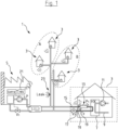
- Fig. 1 shows a fluid pipe network 1 in form of a district heating network for supplying consumer sites 3 with heat from a district heating plant 5.
- the consumer sites 3 may be private households, industrial consumers, or any other type of consumer site that represents a billable entity for a utility provider managing the district heating plant 5.
- the fluid pipe network 1 as shown in Fig. 1 in form of a district heating network is just an example.
- the fluid pipe network 1 could alternatively be a service water distribution network for supplying the consumer sites 3 with water or a gas supply network for supplying the consumer sites 3 with gas.
- the heat is typically transferred from the fluid pipe network 1 to the consumer site 3 by way of a heat exchanger 7 as part of a heating system 9 at the consumer site 3.
- the heating system 9 at the consumer site 3 usually comprises a circulation pump 11 for transporting heated fluid to radiators or underfloor heating.
- the ultrasonic flow meter 13 installed at a pipe 15, 17 connecting the consumer site 3 to the fluid pipe network 1.
- the ultrasonic flow meter 13 is installed at a pipe 15 connecting to a feed line of the district heating network 1.
- the ultrasonic flow meter 13 may be installed at pipe 17 connecting the consumer site 3 to a return line of the district heating network 1.
- the ultrasonic flow meters 13 are in this shown example heat meters that are configured to measure, store and report heat consumption data.
- Two temperature sensors 19 may be provided at the pipes 15, 17 connecting to the feed line and the return line, respectively, for the ultrasonic flow meter 13 to register a temperature differential. In combination with a measured fluid flow in any fluid flow situation the ultrasonic flow meter can provide heat consumption data.
- the ultrasonic flow meters 13 are configured to wirelessly transmit, regularly or sporadically based on a pre-determined schedule, or upon an external command, the heat consumption data via a wireless communication network (not shown) to a head-end-system (HES) 21 of an automatic meter reading system managed by the utility provider.
- the head-end-system (HES) 21 is shown in Fig. 1 to be located within the district heating plant 5. However, it should be understood that the head-end-system (HES) 21 may be located anywhere, e.g. in form of a cloud-based system or a computer server anywhere else.
- the automatic meter reading system may comprise a dedicated wireless communication network or may make use of an existing wireless communication network, e.g. a cellular mobile phone network, for communication between the head-end-system (HES) 21 and the ultrasonic flow meters 13 installed at the different consumer sites 3.
- Fig. 1 shows a situation of a leakage 23 in a feed line of the fluid pipe network 1.
- a utility provider is highly interested in detecting the leakage 23 as quickly as possible, locating the leakage 23 as accurately as possible, and to estimate the size of the leakage 23 as well as possible.
- the ultrasonic flow meters 13 can be used as "microphones" to listen into the fluid pipe network 1 for acoustic leak detection. This is, because the leakage 23 makes a leakage noise that travels along the pipes of the fluid pipe network 1 and/or along the fluid within the pipes.
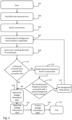
- Acoustic leakage detection is preferably performed in a no-fluid-flow situation, in which there is no fluid-flow in the pipe 15, 17 the ultrasonic flow meter 13 is installed at, or at least the fluid flow is below a flow threshold. Thereby, the acoustic leakage detection is not hampered by fluid flow noise.
- the idea of the present disclosure is now to determine the travelling direction of a sound wave detected by the ultrasonic flow meter and to use the travelling direction as a filter criterium to increase the signal-to-noise ratio, e.g. the average amplitude of the leakage sound divided by the average amplitude of background noise.
- the filtering is based on the insight that most of the expected sound sources for background noise are located at the consumer site 3 and thus the sound waves of the background noise usually travel away from the consumer site 3.
- the leakage noise travels towards the consumer site 3, so that the determined travelling direction can be used to separate the leakage sound from most of the background noises.
- any sound wave travelling towards the consumer site 3 is interpreted as a leakage sound candidate and any sound wave travelling away from the consumer site 3 is interpreted as a background noise.
- the interpretation of the sound wave may be performed directly at the ultrasonic flow meter 13, but preferably at the head-end-system (HES) 21 that receives leakage information data wirelessly from the ultrasonic flow meters 13.
- HES head-end-system
- the head-end-system (HES) 21 uses the leakage information data for interpretation and deciding on whether triggering a leakage alarm or not.
- the information about the travelling direction in the leakage information data may be used as a filter criterium for triggering a leakage alarm or not. Further filter criteria may be applied, such as a minimum amplitude threshold and/or a time-wise and location-wise coincidence of matching leakage information data from several ultrasonic flow meters 13.
- the acoustic leak detection may end at step 125 until it is restarted in step 101.
Landscapes
- Physics & Mathematics (AREA)
- General Physics & Mathematics (AREA)
- Engineering & Computer Science (AREA)
- Fluid Mechanics (AREA)
- Public Health (AREA)
- Hydrology & Water Resources (AREA)
- Life Sciences & Earth Sciences (AREA)
- Water Supply & Treatment (AREA)
- Health & Medical Sciences (AREA)
- Electromagnetism (AREA)
- Acoustics & Sound (AREA)
- Mechanical Engineering (AREA)
- General Engineering & Computer Science (AREA)
- Examining Or Testing Airtightness (AREA)
Claims (21)
- Procédé de détection de fuite acoustique dans un réseau de conduites de fluide (1) au moyen d'au moins un débitmètre à ultrasons (13) installé au niveau d'une conduite (15, 17), dans lequel la conduite (15, 17) raccorde un site consommateur (3) au réseau de conduites de fluide (1), le procédé comprenant :- la détection d'au moins une onde sonore se déplaçant le long de la conduite (15, 17) et/ou le long du fluide à l'intérieur de la conduite (15, 17) à partir d'une source sonore vers au moins un débitmètre à ultrasons (13),- la détermination de la direction de déplacement d'au moins une onde sonore,dans lequel le procédé est caractérisé en ce qu'il comprend en outre :- l'utilisation de la direction de déplacement comme critère de filtre pour augmenter un rapport signal/bruit, dans lequel une onde sonore de ladite au moins une onde sonore est interprétée comme un candidat de son de fuite si la direction de déplacement déterminée de ladite onde sonore est dirigée vers le site consommateur (3) et une onde sonore de ladite au moins une onde sonore est interprétée comme un bruit de fond si la direction de déplacement déterminée de ladite onde sonore est éloignée du site consommateur (3).
- Procédé selon la revendication 1, dans lequel la détermination de la direction de déplacement de ladite onde sonore est basée sur un décalage de phase, sur un décalage temporel et/ou sur une différence d'amplitude entre un premier signal généré par un premier transducteur à ultrasons (T1) d'au moins un débitmètre à ultrasons (13) et un deuxième signal généré par un deuxième transducteur à ultrasons (T2) d'au moins un débitmètres à ultrasons (13), dans lequel le premier transducteur à ultrasons (T1) et le deuxième transducteur à ultrasons (T2) ont une distance axiale (D) l'un par rapport à l'autre.
- Procédé selon une quelconque des revendications précédentes, comprenant en outre l'identification d'au moins une onde sonore comme une superposition d'une première onde sonore se déplaçant vers le site consommateur (3) et d'une deuxième onde sonore s'éloignant du site consommateur (3), dans lequel l'utilisation de la direction de déplacement comme critère de filtre pour augmenter un rapport signal/bruit comprend l'interprétation de la première onde sonore comme un candidat de son de fuite et de la deuxième onde sonore comme un bruit de fond.
- Procédé selon une quelconque des revendications précédentes, comprenant en outre l'identification d'une bande de fréquence dominante dans ladite onde sonore si ladite onde sonore est interprétée comme un bruit de fond et la soustraction de la bande de fréquence dominante d'au moins une onde sonore.
- Procédé selon une quelconque des revendications précédentes, comprenant en outre la définition ou la mise à jour de données d'informations de fuite comprenant des informations relatives à une amplitude de ladite onde sonore et la direction de déplacement de ladite onde sonore.
- Procédé selon la revendication 5, comprenant en outre la mesure d'un débit de fluide à travers le tuyau (15, 17), dans lequel le réglage ou la mise à jour des données d'informations de fuite est effectué régulièrement, en continu ou sporadiquement sur la base d'un programme prédéterminé ou sur commande externe et uniquement lorsqu'un débit de fluide mesuré est inférieur à un seuil de débit ou nul.
- Procédé selon la revendication 5 ou 6, comprenant en outre la transmission sans fil, régulièrement ou sporadiquement sur la base d'un programme prédéterminé ou sur commande externe, des données d'informations de fuite d'au moins un débitmètre à ultrasons (13) à un système de lecture automatique de compteur.
- Procédé selon la revendication 7, dans lequel les données d'informations de fuite sont transmises au cours de lectures programmées de données de débit de fluide et/ou de consommation.
- Procédé selon les revendications 7 ou 8, comprenant en outre la validation des données d'informations de fuite par comparaison avec des données d'informations de fuite reçues dans une fenêtre temporelle prédéterminée par le système de lecture automatique de compteur à partir d'un ou plusieurs autres débitmètres à ultrasons (13) installés sur d'autres conduites raccordant d'autres sites consommateurs (3) au réseau de conduites de fluide (1).
- Procédé selon une quelconque des revendications 5 à 9, comprenant en outre la transmission sans fil d'un signal de commande de détection de fuite d'un système de lecture automatique de compteur à au moins un débitmètre à ultrasons (13), dans lequel le réglage ou la mise à jour des données d'informations de fuite est effectué à la réception du signal de commande de détection de fuite.
- Procédé selon la revendication 10, comprenant en outre la réception par le système de lecture automatique de compteur de données d'informations de fuite provenant d'un d'au moins un débitmètre à ultrasons (13), dans lequel le signal de commande de détection de fuite est transmis à un ou plusieurs débitmètres à ultrasons (13) à proximité dudit débitmètre à ultrasons (13) pour valider lesdites données d'informations.
- Procédé selon une quelconque des revendications précédentes, comprenant en outre la surveillance d'une pluralité de débitmètres à ultrasons (13) installés sur différentes conduites raccordant différents sites consommateurs (3) au réseau de conduites de fluide (1), dans lequel un système de lecture automatique de compteur reçoit des données d'informations de fuite provenant d'un ou de plusieurs de ladite pluralité de débitmètres à ultrasons (13).
- Débitmètre à ultrasons (13) pour mesurer un débit de fluide dans une conduite (15, 17) raccordant un site consommateur (3) à un réseau de conduites de fluide (1), dans lequel le débitmètre à ultrasons (13) comprend :- au moins un transducteur à ultrasons (T1, T2) configuré pour mesurer des signaux ultrasonores pour déterminer un débit de fluide, et- un moyen de traitement en connexion de signal avec au moins un transducteur à ultrasons (T1, T2),dans lequel au moins un transducteur à ultrasons (T1, T2) est en outre configuré pour détecter au moins une onde sonore se déplaçant le long de la conduite (15, 17) et/ou le long du fluide à l'intérieur du tuyau (15, 17) à partir d'une source sonore vers au moins un débitmètre à ultrasons (13) dans une situation sans écoulement de fluide etdans lequel le moyen de traitement est configuré pour déterminer la direction de déplacement d'au moins une des au moins une onde sonore,dans lequel le débitmètre à ultrasons (13) est caractérisé en ce que le moyen de traitement est configuré pour utiliser ou fournir des informations relatives à la direction de déplacement déterminée en tant que critère de filtrage pour augmenter un rapport signal/bruit, dans lequel ladite onde sonore est interprétée comme un candidat de son de fuite si la direction de déplacement déterminée est vers le site consommateur (3) et comme un bruit de fond si la direction de déplacement déterminée est éloignée du site consommateur (3).
- Débitmètre à ultrasons (13) selon la revendication 13, comprenant au moins deux transducteurs à ultrasons (T1, T2) comprenant un premier transducteur à ultrasons (T1) et un deuxième transducteur à ultrasons (T2), dans lequel le premier transducteur à ultrasons (T1) et le deuxième transducteur à ultrasons (T2) ont une distance axiale (D) l'un par rapport à l'autre, dans lequel le moyen de traitement est configuré pour déterminer la direction de déplacement de ladite onde sonore sur la base d'un décalage de phase, d'un décalage temporel et/ou d'une différence d'amplitude entre un premier signal généré par le premier transducteur à ultrasons (T1) et un deuxième signal généré par le deuxième transducteur à ultrasons (T2).
- Débitmètre à ultrasons (13) selon la revendication 13 ou 14, dans lequel la direction de déplacement vers le site consommateur (3) est la direction nominale de l'écoulement de fluide à travers le débitmètre à ultrasons (13).
- Système de détection acoustique de fuite dans un réseau de conduites de fluide (1), le système comprenant au moins un débitmètre à ultrasons (13) selon une quelconque des revendications 13 à 15, comprenant en outre un système de lecture automatique de compteur pour recevoir sans fil des données de débit et/ou de consommation de fluide provenant d'au moins un débitmètres à ultrasons (13), dans lequel au moins un débitmètre à ultrasons (13) est en outre configuré pour transmettre sans fil, régulièrement ou sporadiquement sur la base d'un programme prédéterminé ou sur commande externe, des données d'informations de fuite comprenant des informations relatives à une amplitude de ladite onde sonore et la direction de déplacement de ladite onde sonore.
- Système selon la revendication 16, dans lequel au moins un débitmètre à ultrasons (13) sont configurés pour transmettre les données d'informations de fuite au cours de lectures programmées de données de débit et/ou de consommation de fluide.
- Système selon la revendication 16 ou 17, dans lequel le système de lecture automatique de compteur est configuré pour valider les données d'informations de fuite reçues d'au moins un débitmètres à ultrasons (13) par des données d'informations de fuite reçues dans une fenêtre temporelle prédéterminée à partir d'un ou plusieurs autres débitmètres à ultrasons (13) installés sur d'autres conduites raccordant d'autres sites consommateurs (3) au réseau de conduites de fluide (1).
- Système selon une quelconque des revendications 16 à 18, dans lequel le système de lecture automatique de compteur est configuré pour transmettre sans fil un signal de commande de détection de fuite à au moins un débitmètre à ultrasons (13), dans lequel le débitmètre à ultrasons (13) est configuré pour définir ou mettre à jour les données d'informations de fuite à la réception du signal de commande de détection de fuite.
- Système selon une quelconque des revendications précédentes, comprenant en outre une pluralité de débitmètres à ultrasons (13) installés sur différentes conduites raccordant différents sites consommateurs (3) au réseau de conduites de fluide (1), dans lequel le système de lecture automatique de compteur est configuré pour recevoir des données d'informations de fuite d'un ou plusieurs de ladite pluralité de débitmètres à ultrasons (13).
- Système selon la revendication 16 et 20, dans lequel le système de lecture automatique de compteur est configuré pour transmettre le signal de commande de détection de fuite à un ou plusieurs autres de ladite pluralité de débitmètres ultrasoniques (13) à proximité dudit débitmètre à ultrasons (13) pour valider lesdites données d'informations de fuite.
Priority Applications (4)
| Application Number | Priority Date | Filing Date | Title |
|---|---|---|---|
| EP21171613.9A EP4083592B1 (fr) | 2021-04-30 | 2021-04-30 | Système et procédé de détection de fuite acoustique par l'utilisation d'un débitmètre à ultrasons |
| AU2022202341A AU2022202341B2 (en) | 2021-04-30 | 2022-04-07 | System and method for acoustic leakage detection by use of an ultrasonic flow meter |
| US17/730,521 US12455208B2 (en) | 2021-04-30 | 2022-04-27 | System and method for acoustic leakage detection by use of an ultrasonic flow meter |
| CN202210473893.6A CN115265944A (zh) | 2021-04-30 | 2022-04-29 | 通过使用超声波流量计进行声学泄漏检测的系统和方法 |
Applications Claiming Priority (1)
| Application Number | Priority Date | Filing Date | Title |
|---|---|---|---|
| EP21171613.9A EP4083592B1 (fr) | 2021-04-30 | 2021-04-30 | Système et procédé de détection de fuite acoustique par l'utilisation d'un débitmètre à ultrasons |
Publications (3)
| Publication Number | Publication Date |
|---|---|
| EP4083592A1 EP4083592A1 (fr) | 2022-11-02 |
| EP4083592C0 EP4083592C0 (fr) | 2025-02-26 |
| EP4083592B1 true EP4083592B1 (fr) | 2025-02-26 |
Family
ID=75746511
Family Applications (1)
| Application Number | Title | Priority Date | Filing Date |
|---|---|---|---|
| EP21171613.9A Active EP4083592B1 (fr) | 2021-04-30 | 2021-04-30 | Système et procédé de détection de fuite acoustique par l'utilisation d'un débitmètre à ultrasons |
Country Status (4)
| Country | Link |
|---|---|
| US (1) | US12455208B2 (fr) |
| EP (1) | EP4083592B1 (fr) |
| CN (1) | CN115265944A (fr) |
| AU (1) | AU2022202341B2 (fr) |
Families Citing this family (4)
| Publication number | Priority date | Publication date | Assignee | Title |
|---|---|---|---|---|
| KR102418408B1 (ko) * | 2022-01-21 | 2022-07-06 | 지에스파워주식회사 | 열수요 시계열 데이터에 기반한 지역난방열공급망의 실시간 해석 방법 및 장치 |
| DE102022113311B3 (de) * | 2022-05-25 | 2023-10-26 | Megger Germany Gmbh | Verfahren zur Feststellung und/oder Analyse eines Lecks an einer Leitung für flüssige Medien, insbesondere einer Wasserleitung |
| CN116498908B (zh) | 2023-06-26 | 2023-08-25 | 成都秦川物联网科技股份有限公司 | 基于超声波流量计的智慧燃气管网监测方法和物联网系统 |
| CN117967998A (zh) * | 2024-01-25 | 2024-05-03 | 安徽欧泰祺智慧水务科技有限公司 | 一种基于多声道的管道漏损检测方法和装置 |
Family Cites Families (20)
| Publication number | Priority date | Publication date | Assignee | Title |
|---|---|---|---|---|
| US4327576A (en) * | 1980-05-05 | 1982-05-04 | The United States Of America As Represented By The Secretary Of The Navy | Acoustic leak detector |
| US6389881B1 (en) | 1999-05-27 | 2002-05-21 | Acoustic Systems, Inc. | Method and apparatus for pattern match filtering for real time acoustic pipeline leak detection and location |
| US6453247B1 (en) * | 2000-01-14 | 2002-09-17 | National Research Council Of Canada | PC multimedia-based leak detection system for water transmission and distribution pipes |
| US7096135B2 (en) * | 2004-03-12 | 2006-08-22 | Panametrics, Inc. | Method and system for calculating the transit time of an ultrasonic pulse |
| WO2006069930A2 (fr) * | 2004-12-23 | 2006-07-06 | Endress+Hauser | Reseau de conduites a structure hierarchique pour l'alimentation en eau ou en gaz et/ou pour l'evacuation d'eau sanitaire, procede pour detecter une fuite dans un tel reseau de conduites et procede pour la determination assistee par ordinateur d'une duree de vie theoriquement restante d'une source d'energie renouvelable |
| US7810378B2 (en) * | 2007-06-21 | 2010-10-12 | National Research Council Of Canada | Monitoring of leakage in wastewater force mains and other pipes carrying fluid under pressure |
| BRPI0817874A2 (pt) * | 2007-10-10 | 2015-03-31 | Tecwel As | Método e sistema para registrar e mensuar vazamentos e fluxos |
| US20090299660A1 (en) * | 2008-05-29 | 2009-12-03 | Dan Winter | Method and System to Identify Utility Leaks |
| FR2943696B1 (fr) * | 2009-03-24 | 2016-08-26 | Veolia Eau - Cie Generale Des Eaux | Installation et procede de controle de la qualite de l'eau dans un reseau d'eau potable |
| US8346492B2 (en) * | 2009-10-21 | 2013-01-01 | Acoustic Systems, Inc. | Integrated acoustic leak detection system using intrusive and non-intrusive sensors |
| US8665101B2 (en) | 2009-11-16 | 2014-03-04 | Aquarius Spectrum Ltd. | System method and device for leak detection and localization in a pipe network |
| US7920983B1 (en) * | 2010-03-04 | 2011-04-05 | TaKaDu Ltd. | System and method for monitoring resources in a water utility network |
| US8850871B2 (en) | 2010-09-30 | 2014-10-07 | Siemens Aktiengesellschaft | Pipeline leak location using ultrasonic flowmeters |
| ITMI20122197A1 (it) * | 2012-12-20 | 2014-06-21 | Eni Spa | Metodo e sistema di monitoraggio continuo da remoto dell'integrita' di condotte in pressione e delle proprieta' dei fluidi trasportati |
| CN103292160B (zh) | 2013-06-27 | 2015-11-18 | 陕西师范大学 | 管道泄漏的超声波检测装置及方法 |
| EP3112823A1 (fr) | 2015-07-03 | 2017-01-04 | Kamstrup A/S | Système de surveillance d'un réseau utilitaire |
| EP3112820A1 (fr) * | 2015-07-03 | 2017-01-04 | Kamstrup A/S | Compteur de consommation de fluide avec capteur de bruit |
| US10527515B2 (en) * | 2016-04-21 | 2020-01-07 | Neptune Technology Group Inc. | Ultrasonic flow meter leak detection system and method |
| WO2020247982A1 (fr) * | 2019-06-07 | 2020-12-10 | Orbis Intelligent Systems, Inc. | Dispositifs de détection |
| US12560505B2 (en) * | 2019-04-24 | 2026-02-24 | The University Of Adelaide | Detection of structural anomalies in a pipeline network |
-
2021
- 2021-04-30 EP EP21171613.9A patent/EP4083592B1/fr active Active
-
2022
- 2022-04-07 AU AU2022202341A patent/AU2022202341B2/en active Active
- 2022-04-27 US US17/730,521 patent/US12455208B2/en active Active
- 2022-04-29 CN CN202210473893.6A patent/CN115265944A/zh active Pending
Also Published As
| Publication number | Publication date |
|---|---|
| AU2022202341B2 (en) | 2024-01-04 |
| CN115265944A (zh) | 2022-11-01 |
| US12455208B2 (en) | 2025-10-28 |
| EP4083592C0 (fr) | 2025-02-26 |
| US20220349773A1 (en) | 2022-11-03 |
| AU2022202341A1 (en) | 2022-11-17 |
| EP4083592A1 (fr) | 2022-11-02 |
Similar Documents
| Publication | Publication Date | Title |
|---|---|---|
| EP4083592B1 (fr) | Système et procédé de détection de fuite acoustique par l'utilisation d'un débitmètre à ultrasons | |
| CA2961798C (fr) | Systeme et methode de detection de fuite de debitmetre ultrasonique | |
| KR102189240B1 (ko) | 배송관의 누출 모니터링 장치 및 방법 | |
| US12044604B2 (en) | Method and smart gas internet of things (IoT) system for metering anti-interference of gas ultrasonic meter | |
| CN104011530B (zh) | 用于检测和分析沉淀物的方法和设备 | |
| KR101876730B1 (ko) | 상수도 누수탐지 감시 시스템 | |
| US20080163700A1 (en) | Sensor system for pipe and flow condition monitoring of a pipeline configured for flowing hydrocarbon mixtures | |
| KR101856186B1 (ko) | 초음파유속계를 포함한 하이브리드 레이더유량계 및 이의 동작방법 | |
| CN107709938A (zh) | 具有噪声传感器的流体耗量计 | |
| US10732063B2 (en) | Device for measuring the pressure of a fluid flowing through a pipeline | |
| EA021964B1 (ru) | Способ дистанционного обнаружения, локализации и текущего контроля критических повреждений в трубопроводах | |
| KR101956160B1 (ko) | 누수 탐지 장치 | |
| KR102423388B1 (ko) | 누수센서, 엣지컴퓨팅게이트웨이, 및 관리서버를 포함하는 복합센싱형 IoT 누수감지시스템 | |
| KR101965690B1 (ko) | 상수관로 모니터링 시스템 | |
| JP7641521B2 (ja) | 異常検知システム及び水道メータ | |
| JP7630078B2 (ja) | 漏水検知システム及びこれに用いる超音波流量計 | |
| CN101392869A (zh) | 管道安全预警与泄漏报警方法 | |
| JP2022104811A (ja) | 地震事象を検出する方法 | |
| CN115234847B (zh) | 定位供水管网中的泄漏点的方法 | |
| KR101266038B1 (ko) | 멀티 주파수를 이용한 배관 길이 측정 장치 및 방법 | |
| EP4080184B1 (fr) | Procédé de configuration d'un système de détection de fuite acoustique | |
| JP4862698B2 (ja) | 流量計測装置およびこの装置を用いたガス供給システム | |
| WO2025070681A1 (fr) | Système de détection de fuite d'eau | |
| JP2018053616A (ja) | 下水管路内通信システム、下水管路内監視システム及び下水管路内通信装置 | |
| JP2023169624A (ja) | 配管内の流体モニタリング装置、流体モニタリングシステム及び流体モニタリング方法 |
Legal Events
| Date | Code | Title | Description |
|---|---|---|---|
| PUAI | Public reference made under article 153(3) epc to a published international application that has entered the european phase |
Free format text: ORIGINAL CODE: 0009012 |
|
| STAA | Information on the status of an ep patent application or granted ep patent |
Free format text: STATUS: THE APPLICATION HAS BEEN PUBLISHED |
|
| AK | Designated contracting states |
Kind code of ref document: A1 Designated state(s): AL AT BE BG CH CY CZ DE DK EE ES FI FR GB GR HR HU IE IS IT LI LT LU LV MC MK MT NL NO PL PT RO RS SE SI SK SM TR |
|
| STAA | Information on the status of an ep patent application or granted ep patent |
Free format text: STATUS: REQUEST FOR EXAMINATION WAS MADE |
|
| 17P | Request for examination filed |
Effective date: 20230403 |
|
| RBV | Designated contracting states (corrected) |
Designated state(s): AL AT BE BG CH CY CZ DE DK EE ES FI FR GB GR HR HU IE IS IT LI LT LU LV MC MK MT NL NO PL PT RO RS SE SI SK SM TR |
|
| GRAP | Despatch of communication of intention to grant a patent |
Free format text: ORIGINAL CODE: EPIDOSNIGR1 |
|
| STAA | Information on the status of an ep patent application or granted ep patent |
Free format text: STATUS: GRANT OF PATENT IS INTENDED |
|
| RIC1 | Information provided on ipc code assigned before grant |
Ipc: G01F 1/667 20220101ALI20240916BHEP Ipc: G01F 1/66 20220101ALI20240916BHEP Ipc: F17D 5/06 20060101ALI20240916BHEP Ipc: E03B 7/00 20060101ALI20240916BHEP Ipc: E03B 7/07 20060101ALI20240916BHEP Ipc: G01M 3/24 20060101AFI20240916BHEP |
|
| INTG | Intention to grant announced |
Effective date: 20240925 |
|
| GRAS | Grant fee paid |
Free format text: ORIGINAL CODE: EPIDOSNIGR3 |
|
| GRAA | (expected) grant |
Free format text: ORIGINAL CODE: 0009210 |
|
| STAA | Information on the status of an ep patent application or granted ep patent |
Free format text: STATUS: THE PATENT HAS BEEN GRANTED |
|
| AK | Designated contracting states |
Kind code of ref document: B1 Designated state(s): AL AT BE BG CH CY CZ DE DK EE ES FI FR GB GR HR HU IE IS IT LI LT LU LV MC MK MT NL NO PL PT RO RS SE SI SK SM TR |
|
| REG | Reference to a national code |
Ref country code: GB Ref legal event code: FG4D |
|
| REG | Reference to a national code |
Ref country code: CH Ref legal event code: EP |
|
| REG | Reference to a national code |
Ref country code: DE Ref legal event code: R096 Ref document number: 602021026634 Country of ref document: DE |
|
| REG | Reference to a national code |
Ref country code: IE Ref legal event code: FG4D |
|
| U01 | Request for unitary effect filed |
Effective date: 20250227 |
|
| U07 | Unitary effect registered |
Designated state(s): AT BE BG DE DK EE FI FR IT LT LU LV MT NL PT RO SE SI Effective date: 20250307 |
|
| U20 | Renewal fee for the european patent with unitary effect paid |
Year of fee payment: 5 Effective date: 20250410 |
|
| PG25 | Lapsed in a contracting state [announced via postgrant information from national office to epo] |
Ref country code: RS Free format text: LAPSE BECAUSE OF FAILURE TO SUBMIT A TRANSLATION OF THE DESCRIPTION OR TO PAY THE FEE WITHIN THE PRESCRIBED TIME-LIMIT Effective date: 20250526 |
|
| PG25 | Lapsed in a contracting state [announced via postgrant information from national office to epo] |
Ref country code: PL Free format text: LAPSE BECAUSE OF FAILURE TO SUBMIT A TRANSLATION OF THE DESCRIPTION OR TO PAY THE FEE WITHIN THE PRESCRIBED TIME-LIMIT Effective date: 20250226 |
|
| PG25 | Lapsed in a contracting state [announced via postgrant information from national office to epo] |
Ref country code: ES Free format text: LAPSE BECAUSE OF FAILURE TO SUBMIT A TRANSLATION OF THE DESCRIPTION OR TO PAY THE FEE WITHIN THE PRESCRIBED TIME-LIMIT Effective date: 20250226 |
|
| PG25 | Lapsed in a contracting state [announced via postgrant information from national office to epo] |
Ref country code: NO Free format text: LAPSE BECAUSE OF FAILURE TO SUBMIT A TRANSLATION OF THE DESCRIPTION OR TO PAY THE FEE WITHIN THE PRESCRIBED TIME-LIMIT Effective date: 20250526 Ref country code: IS Free format text: LAPSE BECAUSE OF FAILURE TO SUBMIT A TRANSLATION OF THE DESCRIPTION OR TO PAY THE FEE WITHIN THE PRESCRIBED TIME-LIMIT Effective date: 20250626 |
|
| PG25 | Lapsed in a contracting state [announced via postgrant information from national office to epo] |
Ref country code: HR Free format text: LAPSE BECAUSE OF FAILURE TO SUBMIT A TRANSLATION OF THE DESCRIPTION OR TO PAY THE FEE WITHIN THE PRESCRIBED TIME-LIMIT Effective date: 20250226 |
|
| PG25 | Lapsed in a contracting state [announced via postgrant information from national office to epo] |
Ref country code: GR Free format text: LAPSE BECAUSE OF FAILURE TO SUBMIT A TRANSLATION OF THE DESCRIPTION OR TO PAY THE FEE WITHIN THE PRESCRIBED TIME-LIMIT Effective date: 20250527 |
|
| PG25 | Lapsed in a contracting state [announced via postgrant information from national office to epo] |
Ref country code: SM Free format text: LAPSE BECAUSE OF FAILURE TO SUBMIT A TRANSLATION OF THE DESCRIPTION OR TO PAY THE FEE WITHIN THE PRESCRIBED TIME-LIMIT Effective date: 20250226 |
|
| PG25 | Lapsed in a contracting state [announced via postgrant information from national office to epo] |
Ref country code: CZ Free format text: LAPSE BECAUSE OF FAILURE TO SUBMIT A TRANSLATION OF THE DESCRIPTION OR TO PAY THE FEE WITHIN THE PRESCRIBED TIME-LIMIT Effective date: 20250226 |
|
| PG25 | Lapsed in a contracting state [announced via postgrant information from national office to epo] |
Ref country code: SK Free format text: LAPSE BECAUSE OF FAILURE TO SUBMIT A TRANSLATION OF THE DESCRIPTION OR TO PAY THE FEE WITHIN THE PRESCRIBED TIME-LIMIT Effective date: 20250226 |
|
| REG | Reference to a national code |
Ref country code: CH Ref legal event code: H13 Free format text: ST27 STATUS EVENT CODE: U-0-0-H10-H13 (AS PROVIDED BY THE NATIONAL OFFICE) Effective date: 20251125 |
|
| PG25 | Lapsed in a contracting state [announced via postgrant information from national office to epo] |
Ref country code: MC Free format text: LAPSE BECAUSE OF FAILURE TO SUBMIT A TRANSLATION OF THE DESCRIPTION OR TO PAY THE FEE WITHIN THE PRESCRIBED TIME-LIMIT Effective date: 20250226 |
|
| PLBE | No opposition filed within time limit |
Free format text: ORIGINAL CODE: 0009261 |
|
| STAA | Information on the status of an ep patent application or granted ep patent |
Free format text: STATUS: NO OPPOSITION FILED WITHIN TIME LIMIT |
|
| PG25 | Lapsed in a contracting state [announced via postgrant information from national office to epo] |
Ref country code: CH Free format text: LAPSE BECAUSE OF NON-PAYMENT OF DUE FEES Effective date: 20250430 |
|
| GBPC | Gb: european patent ceased through non-payment of renewal fee |
Effective date: 20250526 |
|
| 26N | No opposition filed |
Effective date: 20251127 |
|
| PG25 | Lapsed in a contracting state [announced via postgrant information from national office to epo] |
Ref country code: GB Free format text: LAPSE BECAUSE OF NON-PAYMENT OF DUE FEES Effective date: 20250526 |
|
| PG25 | Lapsed in a contracting state [announced via postgrant information from national office to epo] |
Ref country code: IE Free format text: LAPSE BECAUSE OF NON-PAYMENT OF DUE FEES Effective date: 20250430 |