EP4083618B1 - Capteur de gaz à ultrasons - Google Patents
Capteur de gaz à ultrasons Download PDFInfo
- Publication number
- EP4083618B1 EP4083618B1 EP20907767.6A EP20907767A EP4083618B1 EP 4083618 B1 EP4083618 B1 EP 4083618B1 EP 20907767 A EP20907767 A EP 20907767A EP 4083618 B1 EP4083618 B1 EP 4083618B1
- Authority
- EP
- European Patent Office
- Prior art keywords
- gas
- ultrasonic
- housing
- gas sensor
- inlet channel
- Prior art date
- Legal status (The legal status is an assumption and is not a legal conclusion. Google has not performed a legal analysis and makes no representation as to the accuracy of the status listed.)
- Active
Links
Images




Classifications
-
- G—PHYSICS
- G01—MEASURING; TESTING
- G01N—INVESTIGATING OR ANALYSING MATERIALS BY DETERMINING THEIR CHEMICAL OR PHYSICAL PROPERTIES
- G01N29/00—Investigating or analysing materials by the use of ultrasonic, sonic or infrasonic waves; Visualisation of the interior of objects by transmitting ultrasonic or sonic waves through the object
- G01N29/22—Details, e.g. general constructional or apparatus details
- G01N29/222—Constructional or flow details for analysing fluids
-
- A—HUMAN NECESSITIES
- A61—MEDICAL OR VETERINARY SCIENCE; HYGIENE
- A61M—DEVICES FOR INTRODUCING MEDIA INTO, OR ONTO, THE BODY; DEVICES FOR TRANSDUCING BODY MEDIA OR FOR TAKING MEDIA FROM THE BODY; DEVICES FOR PRODUCING OR ENDING SLEEP OR STUPOR
- A61M16/00—Devices for influencing the respiratory system of patients by gas treatment, e.g. ventilators; Tracheal tubes
- A61M16/08—Bellows; Connecting tubes ; Water traps; Patient circuits
- A61M16/0816—Joints or connectors
-
- G—PHYSICS
- G01—MEASURING; TESTING
- G01N—INVESTIGATING OR ANALYSING MATERIALS BY DETERMINING THEIR CHEMICAL OR PHYSICAL PROPERTIES
- G01N29/00—Investigating or analysing materials by the use of ultrasonic, sonic or infrasonic waves; Visualisation of the interior of objects by transmitting ultrasonic or sonic waves through the object
- G01N29/02—Analysing fluids
-
- G—PHYSICS
- G01—MEASURING; TESTING
- G01N—INVESTIGATING OR ANALYSING MATERIALS BY DETERMINING THEIR CHEMICAL OR PHYSICAL PROPERTIES
- G01N29/00—Investigating or analysing materials by the use of ultrasonic, sonic or infrasonic waves; Visualisation of the interior of objects by transmitting ultrasonic or sonic waves through the object
- G01N29/22—Details, e.g. general constructional or apparatus details
- G01N29/221—Arrangements for directing or focusing the acoustical waves
-
- A—HUMAN NECESSITIES
- A61—MEDICAL OR VETERINARY SCIENCE; HYGIENE
- A61M—DEVICES FOR INTRODUCING MEDIA INTO, OR ONTO, THE BODY; DEVICES FOR TRANSDUCING BODY MEDIA OR FOR TAKING MEDIA FROM THE BODY; DEVICES FOR PRODUCING OR ENDING SLEEP OR STUPOR
- A61M16/00—Devices for influencing the respiratory system of patients by gas treatment, e.g. ventilators; Tracheal tubes
- A61M16/0003—Accessories therefor, e.g. sensors, vibrators, negative pressure
- A61M2016/003—Accessories therefor, e.g. sensors, vibrators, negative pressure with a flowmeter
-
- A—HUMAN NECESSITIES
- A61—MEDICAL OR VETERINARY SCIENCE; HYGIENE
- A61M—DEVICES FOR INTRODUCING MEDIA INTO, OR ONTO, THE BODY; DEVICES FOR TRANSDUCING BODY MEDIA OR FOR TAKING MEDIA FROM THE BODY; DEVICES FOR PRODUCING OR ENDING SLEEP OR STUPOR
- A61M2205/00—General characteristics of the apparatus
- A61M2205/33—Controlling, regulating or measuring
- A61M2205/3331—Pressure; Flow
- A61M2205/3334—Measuring or controlling the flow rate
-
- A—HUMAN NECESSITIES
- A61—MEDICAL OR VETERINARY SCIENCE; HYGIENE
- A61M—DEVICES FOR INTRODUCING MEDIA INTO, OR ONTO, THE BODY; DEVICES FOR TRANSDUCING BODY MEDIA OR FOR TAKING MEDIA FROM THE BODY; DEVICES FOR PRODUCING OR ENDING SLEEP OR STUPOR
- A61M2205/00—General characteristics of the apparatus
- A61M2205/33—Controlling, regulating or measuring
- A61M2205/3375—Acoustical, e.g. ultrasonic, measuring means
-
- G—PHYSICS
- G01—MEASURING; TESTING
- G01N—INVESTIGATING OR ANALYSING MATERIALS BY DETERMINING THEIR CHEMICAL OR PHYSICAL PROPERTIES
- G01N2291/00—Indexing codes associated with group G01N29/00
- G01N2291/02—Indexing codes associated with the analysed material
- G01N2291/021—Gases
-
- G—PHYSICS
- G01—MEASURING; TESTING
- G01N—INVESTIGATING OR ANALYSING MATERIALS BY DETERMINING THEIR CHEMICAL OR PHYSICAL PROPERTIES
- G01N2291/00—Indexing codes associated with group G01N29/00
- G01N2291/02—Indexing codes associated with the analysed material
- G01N2291/021—Gases
- G01N2291/0215—Mixtures of three or more gases, e.g. air
-
- G—PHYSICS
- G01—MEASURING; TESTING
- G01N—INVESTIGATING OR ANALYSING MATERIALS BY DETERMINING THEIR CHEMICAL OR PHYSICAL PROPERTIES
- G01N2291/00—Indexing codes associated with group G01N29/00
- G01N2291/02—Indexing codes associated with the analysed material
- G01N2291/028—Material parameters
- G01N2291/02809—Concentration of a compound, e.g. measured by a surface mass change
Definitions
- the present disclosure relates to the technical field of gas sensors and more particularly to an ultrasonic gas sensor.
- Medical devices such as ventilators and anesthesia machines, need to monitor the concentration of oxygen, anesthetic gas, hydrogen and other gases in the delivered mixed gas through gas sensors.
- the gas sensor transmits the acquired gas concentration data to the control unit of the ventilator and anesthesia machine.
- the control unit processes the detection data, and adjusts the flow rate of the gas branch according to the detection results.
- patent document CN102441213B provides an anesthesia machine with an electrochemical oxygen sensor. It realizes the measurement of oxygen concentration according to the mechanism that oxygen molecules react with specific chemical substances inside the oxygen sensor to generate electric current. The oxygen concentration is linearly related to the magnitude of the generated current, so the oxygen concentration can be measured according to the magnitude of the generated current.
- the morphology of the chemical substances inside the oxygen sensor will change, and the corresponding relationship between the oxygen concentration and the current will change. Therefore, the oxygen sensor needs to be calibrated or even replaced.
- the existing electrochemical oxygen sensor is provided in the mount of the ventilator or anesthesia machine, and the calibration requires complicated and time-consuming manual intervention, resulting in high cost and short lifespan of the gas sensor.
- Patent document CN106248148B proposes a technical solution for detecting the gas flow entering the sensor by ultrasonic detection technology so as to obtain the oxygen concentration in the gas flow, and provides a through-beam ultrasonic gas sensor.
- Patent document CN103201599B provides a V-shaped ultrasonic flow sensor. In these two gas measurement devices, the gas inlet and the gas outlet are located at two ends of the gas chamber respectively, and need to be connected to the measuring tube section through connecting tubes.
- the measuring tube section usually only has a fixed mounting hole for mounting the oxygen sensor, and there is no additional connecting tube. Therefore, no gas flow channel can be directly formed between the existing ultrasonic sensor and the oxygen sensor mount for matched mounting.
- JP 2014 098563 A discloses a flow measurement apparatus that includes ultrasonic transducers mounted at a top side of a gas passage along which gas flows and operable to transmit a signal along a V-shaped ultrasonic propagation path to be reflected at a bottom side of the gas passage.
- NL 8 303 981 A discloses ultrasonic flowmeter measuring via V-shaped section of pipeline, in which two receivers are arranged at the two ends of the V shape and a transmitter at the junction of the V shape.
- US 2012/186350 A discloses, similar to JP 2014 098563 A , two ultrasonic transducers arranged at a top side of a fluid passage along which fluid flows to transmit a signal into the fluid passage to be reflected at a bottom side of the fluid passage.
- an embodiment of the present disclosure provides an ultrasonic gas sensor.
- the present disclosure replaces the existing electrochemical gas sensor to achieve a long lifespan and avoid manual intervention.
- the present disclosure matches the gas sensor mounting hole of the existing mainstream ventilator, anesthesia machine, etc., and overcomes the defect that the existing traditional through-beam and V-shaped ultrasonic gas sensors need an additional measuring tube section for matched mounting.
- the ultrasonic gas sensor provided by the embodiment of the present disclosure is defined in claim 1 and includes in particular a housing, and a first ultrasonic transducer and a second ultrasonic transducer arranged at a top of an inner chamber of the housing, where the first ultrasonic transducer and the second ultrasonic transducer form a V-shaped ultrasonic transmission path in the housing;
- the housing is sealed by a bottom plate at a bottom of the inner chamber of the housing;
- the bottom of the housing is provided therein with a gas inlet channel and a gas outlet channel; an upper end of the gas inlet channel extends into a left side of the ultrasonic transmission path, and an upper end of the gas outlet channel extends into a right side of the ultrasonic transmission path;
- a lower end of the gas inlet channel and a lower end of the gas outlet channel are converged at a lower side of the bottom plate of the housing, and are separated by a baffle plate protruding from the lower side of the bottom plate of the housing;
- the upper end of the gas inlet channel may be close to the first ultrasonic transducer, and the upper end of the gas outlet channel may be close to the second ultrasonic transducer, such that a measured gas flow entering the inner chamber of the housing passes through a detection area of the first ultrasonic transducer and the second ultrasonic transducer.
- the inner chamber of the housing may be a V-shaped structure with left-right symmetry; the housing may be sealed, and communicates with the gas sensor mount through the gas inlet channel and the gas outlet channel; and the gas inlet channel and the gas outlet channel may be circular.
- the baffle plate may extend downwardly into the gas sensor mount, and may have a lower end not in contact with a bottom of the gas sensor mount, so as to form a splitting gap.
- the baffle plate may extend downwardly into the gas sensor mount, and may have a lower end in contact with a bottom of the gas sensor mount.
- a downwardly extending connecting portion may be provided at a lower end of the housing, through which the housing may be connected to the gas sensor mount; and the connecting portion may be hollow inside and communicates with the gas inlet channel and the gas outlet channel.
- a downward extension length L1 of the baffle plate may be greater than or equal to a downward extension length L2 of the connecting portion.
- the lower end of the housing may be connected to the gas sensor mount by screwing or snapping.
- An upper end of the housing may be provided with a first mounting groove and a second mounting groove, which may be respectively configured to mount the first ultrasonic transducer and the second ultrasonic transducer.
- a diameter-reducing structure close to the upper end of the gas inlet channel may be provided on the ultrasonic transmission path.
- the diameter-reducing structure may be an arc-shaped transition section.
- the baffle plate may be provided with an inclined baffling surface on a side close to the lower end of the gas inlet channel.
- the baffle plate may be provided with an inverted V- or Y-shaped cross-section.
- the present disclosure abandons the traditional gas chamber with a square cross-section, and adopts the gas chamber with a V-shaped cross-section, such that the ultrasonic signal emission path is consistent with the internal shape of the gas chamber, so as to reduce the sensor volume.
- the gas inlet channel and the gas outlet channel have their upper ends separated from each other and lower ends converged, which is matched with the traditional gas sensor mount.
- the present disclosure eliminates the need for an additional connecting tube and utilizes the latest ultrasonic technology to replace the traditional electrochemical gas sensor. It has the advantages of long lifespan, low cost, no need for manual calibration, compact structure, easy mounting and fast response speed.
- the ultrasonic transmission path is reduced in diameter, and the baffle plate is provided with a baffling surface, which accelerates the gas flow, improves the gas concentration measurement response speed, and improves the detection accuracy.
- an embodiment of the present disclosure provides an ultrasonic gas sensor for measuring a concentration of oxygen, anesthetic gas, hydrogen and other gases.
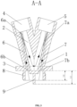
- the ultrasonic gas sensor includes a housing 1 and a pair of ultrasonic transducers, namely a first ultrasonic transducer and a second ultrasonic transducer.
- an inner chamber of the housing 1 is a V-shaped structure with left-right symmetry.
- the first ultrasonic transducer and the second ultrasonic transducer are located at a top of the housing 1, and a V-shaped ultrasonic transmission path 2 is formed between the first ultrasonic transducer and the second ultrasonic transducer.
- the first ultrasonic transducer is provided in a first mounting groove 4, and the second ultrasonic transducer is provided in a second mounting groove 5.
- the first ultrasonic transducer transmits an ultrasonic signal along the V-shaped ultrasonic transmission path 2, and the ultrasonic signal is reflected by a bottom plate 3 at a bottom of the inner chamber of the housing 1.
- the reflected ultrasonic signal continues to propagate to the second ultrasonic transducer along the V-shaped ultrasonic transmission path 2, and is received by the second ultrasonic transducer.
- the housing 1 is further provided with a gas inlet channel 6 and a gas outlet channel 7.
- the gas inlet channel 6 and the gas outlet channel 7 are provided with cylindrical holes.
- An upper end 6a of the gas inlet channel 6 is close to the first ultrasonic transducer, and an upper end 7a of the gas outlet channel 7 is close to the second ultrasonic transducer. Therefore, a measured gas flow entering the inner chamber of the housing 1 can pass through the detection areas of the first ultrasonic transducer and the second ultrasonic transducer, thereby reducing the "dead zone" of ultrasonic detection.
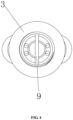
- a lower end 6b of the gas inlet channel 6 and a lower end 7b of the gas outlet channel 7 are converged at a lower side of the bottom plate 3 at the bottom of the housing 1, and are separated through a baffle plate 9 protruding from the lower side of the bottom plate 3 of the housing 1.
- the lower end 6b of the gas inlet channel 6 and the lower end 7b of the gas outlet channel 7 communicate with a gas sensor mount 10.
- a baffle plate 9 is provided between the lower end 6b of the gas inlet channel 6 and the lower end 7b of the gas outlet channel 7.
- the baffle plate 9 extends downwardly from the bottom plate 3 of the housing 1 into the gas sensor mount 10.
- two ends of the gas sensor mount 10 are provided with a gas inlet connector 11 and a gas outlet connector 12 that communicate with each other.
- the gas sensor mount 10 is a rectangular member, and the gas inlet connector 11 and the gas outlet connector 12 are tubular connectors, which are respectively provided on two opposite sides of the gas sensor mount 10.
- the present disclosure does not limit the structure of the gas sensor mount 10.
- Through the baffle plate 9, more gas to be measured entering from the gas inlet connector 11 can enter the V-shaped ultrasonic transmission path 2 through the gas inlet channel 6, and flow out of the V-shaped ultrasonic transmission path 2 through the gas outlet channel 7. This design accelerates the flow of the gas to be measured between the first ultrasonic transducer and the second ultrasonic transducer, and improves the response speed of the oxygen concentration measurement.
- a downwardly extending connecting portion 8 is provided at a lower end of the housing 1.
- the housing 1 is connected to the gas sensor mount 10 through the connecting portion 8.
- the connecting portion 8 is hollow inside and communicates with the gas inlet channel 6 and the gas outlet channel 7.
- a downward extension length L1 of the baffle plate 9 is greater than or equal to a downward extension length L2 of the connecting portion.
- the lower end of the baffle plate 9 is not in contact with the bottom of the gas sensor mount 1, so as to form a splitting gap. In this way, a part of the gas flow entering from the gas inlet connector 11 is blocked by the baffle plate 9 and then enters the gas inlet channel 6, and another part of the gas flow directly flows to the gas outlet connector 12 through the splitting gap.
- This design ensures the flow speed of the gas flow entering the ultrasonic transmission path 2, reduces the influence of oxygen detection on oxygen delivery of the ventilator or anesthesia machine, and eliminates the influence of unstable gas flow on the measurement accuracy of oxygen concentration.
- a temperature sensor is provided in a middle of a gas flow path of the ultrasonic gas sensor.
- the ultrasonic gas sensor of the present disclosure is used in conjunction with an external printed circuit board assembly (PCBA).
- PCBA printed circuit board assembly
- the PCBA is connected to the first ultrasonic transducer, the second ultrasonic transducer and the temperature sensor to realize real-time measurement of gas concentration.
- the application of the ultrasonic gas sensor to the gas sensor mount of the medical device such as the ventilator or the oxygen generator is taken as an example for description.
- a gas sensor mount similar to that used in this embodiment is used to form a detection channel, which is not limited herein.
- the ultrasonic gas sensor of Embodiment 2 differs that of Embodiment 1 in the structures of the V-shaped ultrasonic transmission path 2 and the baffle plate 9.
- a diameter-reducing structure close to the upper end of the gas inlet channel 6 is provided on the ultrasonic transmission path 2.
- an arc-shaped transition section 2a close to the upper end of the gas inlet channel 6 is provided on the ultrasonic transmission path 2.
- the arc-shaped transition section 2a has a smaller diameter when it is closer to the upper end of the gas inlet channel 6. Since the cross-sectional area of the gas flow channel close to the upper end of the gas inlet channel 6 is reduced, the gas flow is accelerated, and the response speed of the gas concentration measurement is improved.
- the baffle plate 9 is provided with an inclined baffling surface 9a on a side close to the lower end 6b of the gas inlet channel.
- the baffling surface 9a promotes more gas to be measured to enter the gas flow at the lower end 6b of the gas inlet channel, and promotes more gas flow to directly enter the lower end 6b of the gas inlet channel.
- This design prevents the measured gas flow from bypassing the baffle plate 9 and directly reaching a gas outlet 7b without entering the lower end 6b of the gas inlet channel. It further accelerates the gas flow and improves the response speed of the gas concentration measurement.
- the baffle plate 9 is provided with an inverted V- or Y-shaped cross-section.
- orientation terms such as “front”, “rear” “upper”, and “lower” are defined based on the positions of the parts in the drawings, which are merely intended for clarity and convenience of expressing the technical solution. It should be understood that the use of such orientation terms should not limit the protection scope claimed by the present disclosure.
Landscapes
- Physics & Mathematics (AREA)
- Health & Medical Sciences (AREA)
- General Health & Medical Sciences (AREA)
- Life Sciences & Earth Sciences (AREA)
- Pathology (AREA)
- Analytical Chemistry (AREA)
- Biochemistry (AREA)
- Chemical & Material Sciences (AREA)
- General Physics & Mathematics (AREA)
- Immunology (AREA)
- Acoustics & Sound (AREA)
- Engineering & Computer Science (AREA)
- Pulmonology (AREA)
- Emergency Medicine (AREA)
- Anesthesiology (AREA)
- Biomedical Technology (AREA)
- Heart & Thoracic Surgery (AREA)
- Hematology (AREA)
- Animal Behavior & Ethology (AREA)
- Public Health (AREA)
- Veterinary Medicine (AREA)
- Investigating Or Analyzing Materials By The Use Of Ultrasonic Waves (AREA)
Claims (11)
- Capteur de gaz à ultrasons, caractérisé en ce qu'il comprend un boîtier (1) et un premier transducteur ultrasonique et un deuxième transducteur ultrasonique disposés respectivement au sommet de la chambre intérieure du boîtier (1), et le premier transducteur ultrasonique et le second transducteur ultrasonique forment un chemin de transmission ultrasonique en forme de V (2) dans le boîtier (1); le boîtier (1) comprend une plaque inférieure (3) disposée au fond de la chambre intérieure du boîtier (1) pour sceller la plaque inférieure (3) du boîtier et le déflecteur (9) dépassant du côté inférieur de la plaque inférieure (3) du boîtier; le premier transducteur ultrasonique disposé au sommet de la chambre intérieure du boîtier (1) transmet un signal ultrasonique le long du chemin de transmission ultrasonique en forme de V (2) pour être réfléchi par la plaque inférieure (3) disposée au fond de la chambre intérieure du boîtier (1); le fond du boîtier (1) est doté d'un canal d'entrée de gaz (6) et d'un canal de sortie de gaz (7). l'extrémité supérieure (6a) du canal d'entrée de gaz (6) s'étend dans le côté gauche du chemin de la transmission ultrasonique (2), une extrémité supérieure (7a) du canal de sortie de gaz (7) s'étend dans le côté droit du chemin de transmission ultrasonique (2), une extrémité inférieure (6b) du canal d'entrée de gaz (6) et une extrémité inférieure (7b) du canal de sortie de gaz (7) convergent à le côté inférieur de la plaque inférieure (3) du boîtier (1), et sont séparés par la plaque déflectrice (9) dépassant du côté inférieur de la plaque inférieure (3) du boîtier (1), et l'extrémité inférieure (6b) du canal d'entrée de gaz (6) et l'extrémité inférieure (7b) du canal de sortie de gaz (7) communiquent avec un montage de capteur de gaz (10), le gaz s'écoule à travers le canal d'entrée de gaz (6) pour entrer et traverser le chemin de transmission ultrasonique en forme de V (2) pour s'écouler dans le canal de sortie de gaz (7).
- Capteur de gaz à ultrasons selon la revendication 1, caractérisé en ce que l'extrémité supérieure du canal d'entrée de gaz est proche du premier transducteur ultrasonique, et l'extrémité supérieure du canal de sortie de gaz est proche du deuxième transducteur ultrasonique, de sorte que un flux de gaz mesuré entrant dans la chambre intérieure du boîtier traverse une zone de détection du premier transducteur ultrasonique et du second transducteur ultrasonique.
- Capteur de gaz à ultrasons selon la revendication 1, dans lequel la chambre intérieure du boîtier est une structure en forme de V avec une symétrie gauche-droite; le boîtier est scellé et communique avec le montage du capteur de gaz par le canal d'entrée de gaz et le canal de sortie de gaz; et le canal d'entrée de gaz et le canal de sortie de gaz sont circulaires.
- Capteur de gaz à ultrasons selon la revendication 3, caractérisé en ce que le boîtier comprend une partie de connexion s'étendant vers le bas qui est disposé à l'extrémité inférieure du boîtier, le boîtier est connecté au montage de capteur de gaz par la partie de connexion et la partie de connexion est creuse à l'intérieur, et communique avec le canal d'entrée de gaz et le canal de sortie de gaz.
- Capteur de gaz à ultrasons selon la revendication 4, caractérisé en ce que une longueur d'extension vers le bas L1 de la plaque déflectrice est supérieure ou égale à une longueur d'extension vers le bas L2 de la partie de connexion.
- Capteur de gaz à ultrasons selon la revendication 4, caractérisé en ce que l'extrémité inférieure du boîtier est filetée ou encliquetée sur la base de montage du capteur de gaz.
- Capteur de gaz à ultrasons selon la revendication 1, caractérisé en ce que une extrémité supérieure du boîtier est dotée d'une première rainure de montage et d'une deuxième rainure de montage, qui sont respectivement configurées pour monter le premier transducteur ultrasonique et le deuxième transducteur ultrasonique.
- Capteur de gaz à ultrasons selon la revendication 1, caractérisé en ce que le chemin de transmission ultrasonique en forme de V est doté d'une structure de réduction de diamètre à proximité de l'extrémité supérieure du canal d'entrée d'air.
- Capteur de gaz à ultrasons selon la revendication 8, caractérisé en ce que la structure de réduction de diamètre est une section de transition en forme d'arc.
- Capteur de gaz à ultrasons selon la revendication 1, caractérisé en ce que la plaque déflectrice est dotée d'une surface déflectrice inclinée sur un côté proche de l'extrémité inférieure du canal d'entrée de gaz.
- Capteur de gaz à ultrasons selon la revendication 10, caractérisé en ce que la section transversal de la plaque déflectrice est en forme de V inverse ou de Y inversé.
Applications Claiming Priority (2)
| Application Number | Priority Date | Filing Date | Title |
|---|---|---|---|
| CN201911370604.4A CN110988115B (zh) | 2019-12-26 | 2019-12-26 | 一种超声波气体传感器 |
| PCT/CN2020/139645 WO2021129840A1 (fr) | 2019-12-26 | 2020-12-25 | Capteur de gaz à ultrasons |
Publications (4)
| Publication Number | Publication Date |
|---|---|
| EP4083618A1 EP4083618A1 (fr) | 2022-11-02 |
| EP4083618A4 EP4083618A4 (fr) | 2023-06-14 |
| EP4083618C0 EP4083618C0 (fr) | 2024-09-04 |
| EP4083618B1 true EP4083618B1 (fr) | 2024-09-04 |
Family
ID=70077498
Family Applications (1)
| Application Number | Title | Priority Date | Filing Date |
|---|---|---|---|
| EP20907767.6A Active EP4083618B1 (fr) | 2019-12-26 | 2020-12-25 | Capteur de gaz à ultrasons |
Country Status (5)
| Country | Link |
|---|---|
| US (1) | US12188907B2 (fr) |
| EP (1) | EP4083618B1 (fr) |
| CN (1) | CN110988115B (fr) |
| HU (1) | HUE069522T2 (fr) |
| WO (1) | WO2021129840A1 (fr) |
Families Citing this family (4)
| Publication number | Priority date | Publication date | Assignee | Title |
|---|---|---|---|---|
| CN110988115B (zh) * | 2019-12-26 | 2025-02-14 | 四方光电(武汉)仪器有限公司 | 一种超声波气体传感器 |
| CN115803617A (zh) * | 2020-07-16 | 2023-03-14 | 松下知识产权经营株式会社 | 物理量测量装置 |
| CN112618893A (zh) * | 2020-12-29 | 2021-04-09 | 深圳市普博科技有限公司 | 通气组件的吸气本体、通气组件以及通气装置 |
| WO2026047109A1 (fr) * | 2024-08-29 | 2026-03-05 | Qaelon Medical | Système et procédé de localisation d'une fuite dans un organe à l'intérieur d'une cavité corporelle |
Family Cites Families (24)
| Publication number | Priority date | Publication date | Assignee | Title |
|---|---|---|---|---|
| NL8303981A (nl) * | 1982-11-19 | 1984-06-18 | Nedap Nv | Ultrasone stroomsnelheidsmeter. |
| US5351522A (en) * | 1993-11-02 | 1994-10-04 | Aequitron Medical, Inc. | Gas sensor |
| US5625156A (en) * | 1996-04-29 | 1997-04-29 | General Motors Corporation | Apparatus for sensing exhaust gas |
| US5844148A (en) * | 1997-07-30 | 1998-12-01 | Pittway Corporation | Detector with adjustable sampling tubes |
| JP2006308401A (ja) * | 2005-04-28 | 2006-11-09 | Daiichi Nekken Co Ltd | 腐蝕性ガス分析センサー |
| JP5728657B2 (ja) * | 2009-10-01 | 2015-06-03 | パナソニックIpマネジメント株式会社 | 超音波流量計測ユニット |
| CN201803811U (zh) * | 2010-08-31 | 2011-04-20 | 哈尔滨圣昌科技开发有限公司 | 内孔横截面形状为六角形的超声波热量表基表 |
| CN102441213B (zh) | 2010-10-09 | 2015-08-19 | 深圳迈瑞生物医疗电子股份有限公司 | 氧电池座组件、氧电池组件及麻醉机 |
| CN201828541U (zh) * | 2010-10-26 | 2011-05-11 | 安徽蓝盾光电子股份有限公司 | 电化学气体传感器用气体检测气室 |
| JP2012103087A (ja) | 2010-11-10 | 2012-05-31 | Panasonic Corp | 超音波流量計測ユニット |
| CN103630271A (zh) * | 2012-08-23 | 2014-03-12 | 郑文虎 | 一种缩径式结构超声波热量表 |
| JP6060378B2 (ja) * | 2012-11-13 | 2017-01-18 | パナソニックIpマネジメント株式会社 | 流量計測装置 |
| DE102014106008B4 (de) | 2014-04-29 | 2023-12-07 | Valeo Schalter Und Sensoren Gmbh | Verfahren zum Betreiben einer Ultraschallsensorvorrichtung eines Kraftfahrzeugs, Ultraschallsensorvorrichtung und Kraftfahrzeug |
| CN204536268U (zh) * | 2015-04-23 | 2015-08-05 | 连云港腾越电子科技有限公司 | 利用超声波检测通水管道中气体含量的装置 |
| GB201611446D0 (en) * | 2016-06-30 | 2016-08-17 | Surface Measurement Systems Ltd | Method and apparatus for measurement of vapour sorption, and sensor for use therein |
| CN106248148B (zh) | 2016-09-22 | 2019-10-22 | 深圳市润普科技有限公司 | 超声波气体传感器 |
| CN206362763U (zh) * | 2016-11-08 | 2017-07-28 | 深圳市吉安达科技有限公司 | 气体探测器的管道安装装置 |
| EP3559651B1 (fr) | 2016-12-23 | 2023-01-25 | Eaton Intelligent Power Limited | Capteur de gaz à ultrasons |
| CN208536932U (zh) * | 2018-08-08 | 2019-02-22 | 北京名旭测控科技有限公司 | 一种反射式双声道超声波气体流量计流道 |
| KR102294787B1 (ko) * | 2019-03-25 | 2021-08-27 | 한국전자기술연구원 | 초음파 스마트 가스미터 측정방법 및 시스템 |
| CN210135957U (zh) * | 2019-08-26 | 2020-03-10 | 武汉友讯达科技有限公司 | 超声波燃气表及燃气管路 |
| CN211697651U (zh) * | 2019-12-26 | 2020-10-16 | 湖北锐意自控系统有限公司 | 一种超声波气体传感器 |
| CN110988115B (zh) * | 2019-12-26 | 2025-02-14 | 四方光电(武汉)仪器有限公司 | 一种超声波气体传感器 |
| CN210952976U (zh) * | 2019-12-31 | 2020-07-07 | 武汉友讯达科技有限公司 | 一种对射测量燃气表 |
-
2019
- 2019-12-26 CN CN201911370604.4A patent/CN110988115B/zh active Active
-
2020
- 2020-12-25 EP EP20907767.6A patent/EP4083618B1/fr active Active
- 2020-12-25 WO PCT/CN2020/139645 patent/WO2021129840A1/fr not_active Ceased
- 2020-12-25 HU HUE20907767A patent/HUE069522T2/hu unknown
-
2022
- 2022-06-06 US US17/832,728 patent/US12188907B2/en active Active
Also Published As
| Publication number | Publication date |
|---|---|
| WO2021129840A1 (fr) | 2021-07-01 |
| US20220299480A1 (en) | 2022-09-22 |
| CN110988115B (zh) | 2025-02-14 |
| EP4083618A1 (fr) | 2022-11-02 |
| EP4083618C0 (fr) | 2024-09-04 |
| US12188907B2 (en) | 2025-01-07 |
| HUE069522T2 (hu) | 2025-03-28 |
| CN110988115A (zh) | 2020-04-10 |
| EP4083618A4 (fr) | 2023-06-14 |
Similar Documents
| Publication | Publication Date | Title |
|---|---|---|
| EP4083618B1 (fr) | Capteur de gaz à ultrasons | |
| US9285257B2 (en) | Gas meter for ultrasound measurements in a breathing apparatus having self-draining conduit arrangement | |
| JP2020144145A5 (fr) | ||
| JP6155138B2 (ja) | 燃料消費量測定装置 | |
| US8336375B2 (en) | Flow cell assembly for fluid sensors | |
| EP2664918A1 (fr) | Analyseur d'haleine et module de détection d'alcool détachable | |
| US7093501B2 (en) | Process and device for measuring flow parameters | |
| JP4275990B2 (ja) | 流量センサ | |
| EP2028457A1 (fr) | Débitmètre multivortex incorporant un manomètre | |
| US9897570B2 (en) | Dissolved oxygen measurement system and method of calibrating dissolved oxygen meter | |
| KR101371678B1 (ko) | 음주측정기 | |
| US20140298888A1 (en) | Segmented ultrasonic transducer and gas bubble sensing device comprising the same | |
| CN210294106U (zh) | 管内气泡检测装置 | |
| CN208672051U (zh) | 电子烟气体流量检测系统 | |
| US6289718B1 (en) | Arrangement for detecting a gaseous component in a gas flow | |
| CN211697651U (zh) | 一种超声波气体传感器 | |
| RU2009115246A (ru) | Устройство молекулярного обмена | |
| CN217465878U (zh) | 一种超声波气体传感器 | |
| CN109009123A (zh) | 一体化气路板、气体处理装置及其医疗设备 | |
| US8453524B2 (en) | Solution feeding device | |
| JP5100168B2 (ja) | ポータブル型脈動計 | |
| JP2015036623A (ja) | 燃料消費量演算装置、燃料消費量演算プログラム及び燃料消費量測定装置 | |
| CN210802574U (zh) | 一种插入式管道气体测量仪 | |
| CN209559111U (zh) | 一种基于光纤传感的结构变形装置 | |
| CN211122437U (zh) | 一种柴油车车尾气检测装置 |
Legal Events
| Date | Code | Title | Description |
|---|---|---|---|
| STAA | Information on the status of an ep patent application or granted ep patent |
Free format text: STATUS: THE INTERNATIONAL PUBLICATION HAS BEEN MADE |
|
| PUAI | Public reference made under article 153(3) epc to a published international application that has entered the european phase |
Free format text: ORIGINAL CODE: 0009012 |
|
| STAA | Information on the status of an ep patent application or granted ep patent |
Free format text: STATUS: REQUEST FOR EXAMINATION WAS MADE |
|
| 17P | Request for examination filed |
Effective date: 20220630 |
|
| AK | Designated contracting states |
Kind code of ref document: A1 Designated state(s): AL AT BE BG CH CY CZ DE DK EE ES FI FR GB GR HR HU IE IS IT LI LT LU LV MC MK MT NL NO PL PT RO RS SE SI SK SM TR |
|
| DAV | Request for validation of the european patent (deleted) | ||
| DAX | Request for extension of the european patent (deleted) | ||
| A4 | Supplementary search report drawn up and despatched |
Effective date: 20230512 |
|
| RIC1 | Information provided on ipc code assigned before grant |
Ipc: A61M 16/08 20060101ALI20230508BHEP Ipc: A61M 16/00 20060101ALI20230508BHEP Ipc: G01N 29/22 20060101ALI20230508BHEP Ipc: G01F 1/667 20220101ALI20230508BHEP Ipc: G01N 29/02 20060101AFI20230508BHEP |
|
| GRAP | Despatch of communication of intention to grant a patent |
Free format text: ORIGINAL CODE: EPIDOSNIGR1 |
|
| STAA | Information on the status of an ep patent application or granted ep patent |
Free format text: STATUS: GRANT OF PATENT IS INTENDED |
|
| INTG | Intention to grant announced |
Effective date: 20240405 |
|
| GRAS | Grant fee paid |
Free format text: ORIGINAL CODE: EPIDOSNIGR3 |
|
| GRAA | (expected) grant |
Free format text: ORIGINAL CODE: 0009210 |
|
| STAA | Information on the status of an ep patent application or granted ep patent |
Free format text: STATUS: THE PATENT HAS BEEN GRANTED |
|
| AK | Designated contracting states |
Kind code of ref document: B1 Designated state(s): AL AT BE BG CH CY CZ DE DK EE ES FI FR GB GR HR HU IE IS IT LI LT LU LV MC MK MT NL NO PL PT RO RS SE SI SK SM TR |
|
| REG | Reference to a national code |
Ref country code: GB Ref legal event code: FG4D |
|
| REG | Reference to a national code |
Ref country code: CH Ref legal event code: EP |
|
| REG | Reference to a national code |
Ref country code: IE Ref legal event code: FG4D |
|
| REG | Reference to a national code |
Ref country code: DE Ref legal event code: R096 Ref document number: 602020037337 Country of ref document: DE |
|
| U01 | Request for unitary effect filed |
Effective date: 20240930 |
|
| U07 | Unitary effect registered |
Designated state(s): AT BE BG DE DK EE FI FR IT LT LU LV MT NL PT RO SE SI Effective date: 20241024 |
|
| U20 | Renewal fee for the european patent with unitary effect paid |
Year of fee payment: 5 Effective date: 20241127 |
|
| PG25 | Lapsed in a contracting state [announced via postgrant information from national office to epo] |
Ref country code: NO Free format text: LAPSE BECAUSE OF FAILURE TO SUBMIT A TRANSLATION OF THE DESCRIPTION OR TO PAY THE FEE WITHIN THE PRESCRIBED TIME-LIMIT Effective date: 20241204 |
|
| PG25 | Lapsed in a contracting state [announced via postgrant information from national office to epo] |
Ref country code: GR Free format text: LAPSE BECAUSE OF FAILURE TO SUBMIT A TRANSLATION OF THE DESCRIPTION OR TO PAY THE FEE WITHIN THE PRESCRIBED TIME-LIMIT Effective date: 20241205 Ref country code: PL Free format text: LAPSE BECAUSE OF FAILURE TO SUBMIT A TRANSLATION OF THE DESCRIPTION OR TO PAY THE FEE WITHIN THE PRESCRIBED TIME-LIMIT Effective date: 20240904 |
|
| PG25 | Lapsed in a contracting state [announced via postgrant information from national office to epo] |
Ref country code: HR Free format text: LAPSE BECAUSE OF FAILURE TO SUBMIT A TRANSLATION OF THE DESCRIPTION OR TO PAY THE FEE WITHIN THE PRESCRIBED TIME-LIMIT Effective date: 20240904 |
|
| PG25 | Lapsed in a contracting state [announced via postgrant information from national office to epo] |
Ref country code: ES Free format text: LAPSE BECAUSE OF FAILURE TO SUBMIT A TRANSLATION OF THE DESCRIPTION OR TO PAY THE FEE WITHIN THE PRESCRIBED TIME-LIMIT Effective date: 20240904 Ref country code: RS Free format text: LAPSE BECAUSE OF FAILURE TO SUBMIT A TRANSLATION OF THE DESCRIPTION OR TO PAY THE FEE WITHIN THE PRESCRIBED TIME-LIMIT Effective date: 20241204 |
|
| PG25 | Lapsed in a contracting state [announced via postgrant information from national office to epo] |
Ref country code: RS Free format text: LAPSE BECAUSE OF FAILURE TO SUBMIT A TRANSLATION OF THE DESCRIPTION OR TO PAY THE FEE WITHIN THE PRESCRIBED TIME-LIMIT Effective date: 20241204 Ref country code: PL Free format text: LAPSE BECAUSE OF FAILURE TO SUBMIT A TRANSLATION OF THE DESCRIPTION OR TO PAY THE FEE WITHIN THE PRESCRIBED TIME-LIMIT Effective date: 20240904 Ref country code: NO Free format text: LAPSE BECAUSE OF FAILURE TO SUBMIT A TRANSLATION OF THE DESCRIPTION OR TO PAY THE FEE WITHIN THE PRESCRIBED TIME-LIMIT Effective date: 20241204 Ref country code: HR Free format text: LAPSE BECAUSE OF FAILURE TO SUBMIT A TRANSLATION OF THE DESCRIPTION OR TO PAY THE FEE WITHIN THE PRESCRIBED TIME-LIMIT Effective date: 20240904 Ref country code: GR Free format text: LAPSE BECAUSE OF FAILURE TO SUBMIT A TRANSLATION OF THE DESCRIPTION OR TO PAY THE FEE WITHIN THE PRESCRIBED TIME-LIMIT Effective date: 20241205 Ref country code: ES Free format text: LAPSE BECAUSE OF FAILURE TO SUBMIT A TRANSLATION OF THE DESCRIPTION OR TO PAY THE FEE WITHIN THE PRESCRIBED TIME-LIMIT Effective date: 20240904 |
|
| REG | Reference to a national code |
Ref country code: HU Ref legal event code: AG4A Ref document number: E069522 Country of ref document: HU |
|
| PG25 | Lapsed in a contracting state [announced via postgrant information from national office to epo] |
Ref country code: IS Free format text: LAPSE BECAUSE OF FAILURE TO SUBMIT A TRANSLATION OF THE DESCRIPTION OR TO PAY THE FEE WITHIN THE PRESCRIBED TIME-LIMIT Effective date: 20250104 |
|
| PG25 | Lapsed in a contracting state [announced via postgrant information from national office to epo] |
Ref country code: SM Free format text: LAPSE BECAUSE OF FAILURE TO SUBMIT A TRANSLATION OF THE DESCRIPTION OR TO PAY THE FEE WITHIN THE PRESCRIBED TIME-LIMIT Effective date: 20240904 |
|
| PG25 | Lapsed in a contracting state [announced via postgrant information from national office to epo] |
Ref country code: CZ Free format text: LAPSE BECAUSE OF FAILURE TO SUBMIT A TRANSLATION OF THE DESCRIPTION OR TO PAY THE FEE WITHIN THE PRESCRIBED TIME-LIMIT Effective date: 20240904 |
|
| PG25 | Lapsed in a contracting state [announced via postgrant information from national office to epo] |
Ref country code: SK Free format text: LAPSE BECAUSE OF FAILURE TO SUBMIT A TRANSLATION OF THE DESCRIPTION OR TO PAY THE FEE WITHIN THE PRESCRIBED TIME-LIMIT Effective date: 20240904 |
|
| PG25 | Lapsed in a contracting state [announced via postgrant information from national office to epo] |
Ref country code: MC Free format text: LAPSE BECAUSE OF FAILURE TO SUBMIT A TRANSLATION OF THE DESCRIPTION OR TO PAY THE FEE WITHIN THE PRESCRIBED TIME-LIMIT Effective date: 20240904 |
|
| PLBE | No opposition filed within time limit |
Free format text: ORIGINAL CODE: 0009261 |
|
| STAA | Information on the status of an ep patent application or granted ep patent |
Free format text: STATUS: NO OPPOSITION FILED WITHIN TIME LIMIT |
|
| REG | Reference to a national code |
Ref country code: CH Ref legal event code: PL |
|
| 26N | No opposition filed |
Effective date: 20250605 |
|
| PG25 | Lapsed in a contracting state [announced via postgrant information from national office to epo] |
Ref country code: CH Free format text: LAPSE BECAUSE OF NON-PAYMENT OF DUE FEES Effective date: 20241231 |
|
| PG25 | Lapsed in a contracting state [announced via postgrant information from national office to epo] |
Ref country code: IE Free format text: LAPSE BECAUSE OF NON-PAYMENT OF DUE FEES Effective date: 20241225 |
|
| PGFP | Annual fee paid to national office [announced via postgrant information from national office to epo] |
Ref country code: GB Payment date: 20251124 Year of fee payment: 6 |
|
| PGFP | Annual fee paid to national office [announced via postgrant information from national office to epo] |
Ref country code: HU Payment date: 20251223 Year of fee payment: 6 |
|
| U20 | Renewal fee for the european patent with unitary effect paid |
Year of fee payment: 6 Effective date: 20251229 |