EP4083659B1 - Vorrichtung und verfahren zur verarbeitung von signalen aus einer gesamtheit von ultraschallwandlern - Google Patents
Vorrichtung und verfahren zur verarbeitung von signalen aus einer gesamtheit von ultraschallwandlern Download PDFInfo
- Publication number
- EP4083659B1 EP4083659B1 EP22169557.0A EP22169557A EP4083659B1 EP 4083659 B1 EP4083659 B1 EP 4083659B1 EP 22169557 A EP22169557 A EP 22169557A EP 4083659 B1 EP4083659 B1 EP 4083659B1
- Authority
- EP
- European Patent Office
- Prior art keywords
- signal
- transducers
- pulses
- signals
- coherence
- Prior art date
- Legal status (The legal status is an assumption and is not a legal conclusion. Google has not performed a legal analysis and makes no representation as to the accuracy of the status listed.)
- Active
Links
Images




Classifications
-
- G—PHYSICS
- G01—MEASURING; TESTING
- G01S—RADIO DIRECTION-FINDING; RADIO NAVIGATION; DETERMINING DISTANCE OR VELOCITY BY USE OF RADIO WAVES; LOCATING OR PRESENCE-DETECTING BY USE OF THE REFLECTION OR RERADIATION OF RADIO WAVES; ANALOGOUS ARRANGEMENTS USING OTHER WAVES
- G01S7/00—Details of systems according to groups G01S13/00, G01S15/00, G01S17/00
- G01S7/52—Details of systems according to groups G01S13/00, G01S15/00, G01S17/00 of systems according to group G01S15/00
- G01S7/523—Details of pulse systems
- G01S7/526—Receivers
- G01S7/53—Means for transforming coordinates or for evaluating data, e.g. using computers
- G01S7/533—Data rate converters
-
- G—PHYSICS
- G01—MEASURING; TESTING
- G01S—RADIO DIRECTION-FINDING; RADIO NAVIGATION; DETERMINING DISTANCE OR VELOCITY BY USE OF RADIO WAVES; LOCATING OR PRESENCE-DETECTING BY USE OF THE REFLECTION OR RERADIATION OF RADIO WAVES; ANALOGOUS ARRANGEMENTS USING OTHER WAVES
- G01S7/00—Details of systems according to groups G01S13/00, G01S15/00, G01S17/00
- G01S7/52—Details of systems according to groups G01S13/00, G01S15/00, G01S17/00 of systems according to group G01S15/00
- G01S7/52003—Techniques for enhancing spatial resolution of targets
-
- G—PHYSICS
- G01—MEASURING; TESTING
- G01S—RADIO DIRECTION-FINDING; RADIO NAVIGATION; DETERMINING DISTANCE OR VELOCITY BY USE OF RADIO WAVES; LOCATING OR PRESENCE-DETECTING BY USE OF THE REFLECTION OR RERADIATION OF RADIO WAVES; ANALOGOUS ARRANGEMENTS USING OTHER WAVES
- G01S15/00—Systems using the reflection or reradiation of acoustic waves, e.g. sonar systems
- G01S15/88—Sonar systems specially adapted for specific applications
- G01S15/89—Sonar systems specially adapted for specific applications for mapping or imaging
- G01S15/8906—Short-range imaging systems; Acoustic microscope systems using pulse-echo techniques
-
- G—PHYSICS
- G01—MEASURING; TESTING
- G01S—RADIO DIRECTION-FINDING; RADIO NAVIGATION; DETERMINING DISTANCE OR VELOCITY BY USE OF RADIO WAVES; LOCATING OR PRESENCE-DETECTING BY USE OF THE REFLECTION OR RERADIATION OF RADIO WAVES; ANALOGOUS ARRANGEMENTS USING OTHER WAVES
- G01S15/00—Systems using the reflection or reradiation of acoustic waves, e.g. sonar systems
- G01S15/02—Systems using the reflection or reradiation of acoustic waves, e.g. sonar systems using reflection of acoustic waves
- G01S15/06—Systems determining the position data of a target
- G01S15/42—Simultaneous measurement of distance and other co-ordinates
-
- G—PHYSICS
- G01—MEASURING; TESTING
- G01S—RADIO DIRECTION-FINDING; RADIO NAVIGATION; DETERMINING DISTANCE OR VELOCITY BY USE OF RADIO WAVES; LOCATING OR PRESENCE-DETECTING BY USE OF THE REFLECTION OR RERADIATION OF RADIO WAVES; ANALOGOUS ARRANGEMENTS USING OTHER WAVES
- G01S7/00—Details of systems according to groups G01S13/00, G01S15/00, G01S17/00
- G01S7/52—Details of systems according to groups G01S13/00, G01S15/00, G01S17/00 of systems according to group G01S15/00
- G01S7/523—Details of pulse systems
- G01S7/526—Receivers
- G01S7/527—Extracting wanted echo signals
- G01S7/5273—Extracting wanted echo signals using digital techniques
-
- G—PHYSICS
- G01—MEASURING; TESTING
- G01S—RADIO DIRECTION-FINDING; RADIO NAVIGATION; DETERMINING DISTANCE OR VELOCITY BY USE OF RADIO WAVES; LOCATING OR PRESENCE-DETECTING BY USE OF THE REFLECTION OR RERADIATION OF RADIO WAVES; ANALOGOUS ARRANGEMENTS USING OTHER WAVES
- G01S7/00—Details of systems according to groups G01S13/00, G01S15/00, G01S17/00
- G01S7/52—Details of systems according to groups G01S13/00, G01S15/00, G01S17/00 of systems according to group G01S15/00
- G01S7/539—Details of systems according to groups G01S13/00, G01S15/00, G01S17/00 of systems according to group G01S15/00 using analysis of echo signal for target characterisation; Target signature; Target cross-section
-
- G—PHYSICS
- G06—COMPUTING OR CALCULATING; COUNTING
- G06F—ELECTRIC DIGITAL DATA PROCESSING
- G06F3/00—Input arrangements for transferring data to be processed into a form capable of being handled by the computer; Output arrangements for transferring data from processing unit to output unit, e.g. interface arrangements
- G06F3/01—Input arrangements or combined input and output arrangements for interaction between user and computer
- G06F3/017—Gesture based interaction, e.g. based on a set of recognized hand gestures
-
- G—PHYSICS
- G10—MUSICAL INSTRUMENTS; ACOUSTICS
- G10K—SOUND-PRODUCING DEVICES; METHODS OR DEVICES FOR PROTECTING AGAINST, OR FOR DAMPING, NOISE OR OTHER ACOUSTIC WAVES IN GENERAL; ACOUSTICS NOT OTHERWISE PROVIDED FOR
- G10K11/00—Methods or devices for transmitting, conducting or directing sound in general; Methods or devices for protecting against, or for damping, noise or other acoustic waves in general
- G10K11/18—Methods or devices for transmitting, conducting or directing sound
- G10K11/20—Reflecting arrangements
-
- G—PHYSICS
- G10—MUSICAL INSTRUMENTS; ACOUSTICS
- G10K—SOUND-PRODUCING DEVICES; METHODS OR DEVICES FOR PROTECTING AGAINST, OR FOR DAMPING, NOISE OR OTHER ACOUSTIC WAVES IN GENERAL; ACOUSTICS NOT OTHERWISE PROVIDED FOR
- G10K11/00—Methods or devices for transmitting, conducting or directing sound in general; Methods or devices for protecting against, or for damping, noise or other acoustic waves in general
- G10K11/18—Methods or devices for transmitting, conducting or directing sound
- G10K11/26—Sound-focusing or directing, e.g. scanning
- G10K11/34—Sound-focusing or directing, e.g. scanning using electrical steering of transducer arrays, e.g. beam steering
- G10K11/341—Circuits therefor
- G10K11/346—Circuits therefor using phase variation
-
- G—PHYSICS
- G01—MEASURING; TESTING
- G01S—RADIO DIRECTION-FINDING; RADIO NAVIGATION; DETERMINING DISTANCE OR VELOCITY BY USE OF RADIO WAVES; LOCATING OR PRESENCE-DETECTING BY USE OF THE REFLECTION OR RERADIATION OF RADIO WAVES; ANALOGOUS ARRANGEMENTS USING OTHER WAVES
- G01S15/00—Systems using the reflection or reradiation of acoustic waves, e.g. sonar systems
- G01S15/88—Sonar systems specially adapted for specific applications
- G01S15/89—Sonar systems specially adapted for specific applications for mapping or imaging
- G01S15/8906—Short-range imaging systems; Acoustic microscope systems using pulse-echo techniques
- G01S15/8909—Short-range imaging systems; Acoustic microscope systems using pulse-echo techniques using a static transducer configuration
- G01S15/8915—Short-range imaging systems; Acoustic microscope systems using pulse-echo techniques using a static transducer configuration using a transducer array
-
- G—PHYSICS
- G01—MEASURING; TESTING
- G01S—RADIO DIRECTION-FINDING; RADIO NAVIGATION; DETERMINING DISTANCE OR VELOCITY BY USE OF RADIO WAVES; LOCATING OR PRESENCE-DETECTING BY USE OF THE REFLECTION OR RERADIATION OF RADIO WAVES; ANALOGOUS ARRANGEMENTS USING OTHER WAVES
- G01S7/00—Details of systems according to groups G01S13/00, G01S15/00, G01S17/00
- G01S7/52—Details of systems according to groups G01S13/00, G01S15/00, G01S17/00 of systems according to group G01S15/00
- G01S7/52017—Details of systems according to groups G01S13/00, G01S15/00, G01S17/00 of systems according to group G01S15/00 particularly adapted to short-range imaging
- G01S7/52023—Details of receivers
- G01S7/52025—Details of receivers for pulse systems
- G01S7/52026—Extracting wanted echo signals
- G01S7/52028—Extracting wanted echo signals using digital techniques
-
- G—PHYSICS
- G01—MEASURING; TESTING
- G01S—RADIO DIRECTION-FINDING; RADIO NAVIGATION; DETERMINING DISTANCE OR VELOCITY BY USE OF RADIO WAVES; LOCATING OR PRESENCE-DETECTING BY USE OF THE REFLECTION OR RERADIATION OF RADIO WAVES; ANALOGOUS ARRANGEMENTS USING OTHER WAVES
- G01S7/00—Details of systems according to groups G01S13/00, G01S15/00, G01S17/00
- G01S7/52—Details of systems according to groups G01S13/00, G01S15/00, G01S17/00 of systems according to group G01S15/00
- G01S7/52017—Details of systems according to groups G01S13/00, G01S15/00, G01S17/00 of systems according to group G01S15/00 particularly adapted to short-range imaging
- G01S7/52023—Details of receivers
- G01S7/52036—Details of receivers using analysis of echo signal for target characterisation
Definitions
- the invention generally relates to the field of detection systems and in particular to a device and a method for processing the signal from a set of ultrasonic transducers.
- Ultrasonic sensors are today used in many applications such as spatial localization, gesture detection, fingerprint recognition, biomedical images, etc.
- An ultrasonic sensor emits short, high-frequency sound pulses at regular intervals. These pulses travel through the air at the speed of sound. When they encounter an object, they are reflected and return as an echo to the sensor. This then calculates the distance separating it from the target based on the time elapsed between the transmission of the signal and the reception of the echo.
- An ultrasonic sensor emits short, high-frequency sound pulses at regular intervals. These pulses travel through the air at the speed of sound. When they encounter an object, they are reflected and return as an echo to the sensor. This then calculates the distance separating it from the target based on the time elapsed between the transmission of the signal and the reception of the echo.
- An ultrasonic sensor emits short, high-frequency sound pulses at regular intervals.
- These pulses travel through the air at the speed of sound. When they encounter an object, they are reflected and return as an echo to the sensor. This then calculates the distance separating it from the target based on the time elapsed between the transmission of the signal and the reception of the echo.
- An ultrasonic sensor emits short, high-frequency ultrasonic signals at regular intervals or continuously. These pulses travel through the air at the speed of sound. When they encounter an object, they are reflected and return as an echo to the sensor which can then calculate the distance which separates it from the object, using the time elapsed between the emission of the signal and the reception of the signal. echo from the sensor.
- ultrasonic sensors often requires relatively heavy near-sensor signal processing to extract relevant information, depending on the application, such as for example the distance and angle for object localization, the type of movements for gesture detection, validation information in the case of fingerprint recognition, diagnostic information in the case of a biomedical image.
- the ultrasonic modality of ultrasonic transducers for time-of-flight measurement is not sensitive to the same objects as other modalities (RADAR, optical) (for example, an ultrasonic wave will be reflected by a transparent window).
- the ultrasonic signal from a single ultrasonic transducer is generally very non-directive, the ultrasonic wave being emitted or received in an emission cone with an angle of typically several tens of degrees. It follows that the processing of the transmitted signal provides object localization with large angular uncertainty when an ultrasonic sensor is used.
- Triangulation methods involve measuring distance from two (or more) distinct locations. The cross-checking of the two (or more) pieces of information makes it possible to locate an object with improved precision.
- the two source/detector pairs must be well spaced from each other, which is not always possible or desirable in practice, and can pose difficulties. integration.
- the beamsteering/beamforming approach refers to a set of complex techniques which respectively allow the characteristics of the ultrasound beam to be adjusted in transmission (“beamsteering”), or to improve the quality of information measured in reception (“beamforming”).
- beamsteering a set of complex techniques which respectively allow the characteristics of the ultrasound beam to be adjusted in transmission
- beamforming a set of techniques relies on the construction of interference between the signals of a set of transducers which sends/measures the signal with a temporal phase shift, which corresponds to the reception/transmission angle of the plane wave.
- the different transducers of the set of ultrasonic transducers emit signals with a time phase shift so that the acoustic waves generated by the different transducers are constructive, in at least one direction. particular, and destructive in other directions.
- Several emissions with different phase shifts are generally used. Measuring the echoes corresponding to these different emissions makes it possible to improve the angular resolution.
- beamforming a single measurement in reception of the set of transducers can give rise to different processing of the signal, corresponding to different ways of interfering, each corresponding to a direction of observation. It is then possible to determine the angular position of the object.
- beamforming techniques require the different transducers to be located very close together, with a distance between the transducers less than half a wavelength of the signal. Otherwise, the system presents artifacts, that is to say unwanted emission/sensitivity in certain directions. Such artifacts greatly degrade the performance of the system (presence of grating lobes in the directivity diagram of the ultrasound sensor, due to spatial aliasing or “spatial aliasing”).
- the system When transmitting and receiving are produced by different transducers, the system is generally also blind, because the transmission signal can interfere with the reception signal via mechanical or electrical coupling, unless complex decoupling is required.
- a system for processing signals delivered by an ultrasonic sensor, the ultrasonic sensor comprising a set of transducers, at least some of the transducers of the set of transducers being configured to emit signals and/or receive signals. echoes corresponding to the reflection of signals by a detected object, signals being transmitted by a plurality of transducers of the ultrasonic sensor to the processing system in response to the reception of echoes by said transducers, the processing system being configured to determine at least characteristic information relating to the detected object, from the signals received from the transducers of the ultrasonic sensor.
- the processing system comprises a coupling device configured to transform the signals received from at least certain transducers of the set of transducers into pulses, and a pulse processing unit configured to process the pulses delivered by the processing device. coupling.
- the pulse processing unit is configured to determine at least one characteristic information relating to the detected object from the pulses determined by the coupling device for all the signals received from the transducers.
- the pulse processing unit comprises at least one classifier.
- said at least one classifier may comprise a main classifier, the main classifier being an impulse neural network type classifier or non-event classifier.
- said at least one classifier may further comprise a secondary classifier for determining the amplitude of the threshold used by the thresholding unit from a set of possible values of threshold amplitudes from the pulses received from the device coupling.
- the processing system may further include a set of amplifiers, the set of amplifiers comprising at least one amplifier and being configured to amplify the analog voltage of each signal received from the transducer.
- the processing system may further include a set of bandpass filters, the set of bandpass filters comprising at least one bandpass filter and configured to filter the voltage amplified by the set of amplifiers so as to eliminate noise outside the pass band, the signal derived from each signal received from the transducer being the signal delivered by the set of band pass filters.
- the processing system may include a controller configured to adapt one or more shaping parameters of signals received from the transducers based on one or more adaptation criteria using signals from the unit pulse processing.
- the controller can be configured to adapt the threshold used by the thresholding unit as a function of the distance between the ultrasonic sensor and the object, or as a function of the quality of previous measurements carried out by the ultrasonic sensor, the quality being calculated in the pulse domain or after a real number conversion of the pulse density.
- the pulse processing unit may comprise a set of coherence detectors comprising at least one coherence detector and a unit for determining characteristic information, all of the coherence detectors being configured to detect if the signals coming from the transducers, for a given direction of the echoes coming from the object, are coherent from the pulses delivered by the pulse transformation unit, and to deliver said pulses to the characteristic information determination unit if consistency is detected.
- the unit for determining the characteristic information may be a unit for measuring the distance and/or the direction of the echoes coming from the object.
- the unit for determining the characteristic information may be a classifier.
- a coherence detector may include a leakage integrator for measuring an alignment of the edges of the signals received from the transducers of the set of transducers.
- a coherence detector may include a windowing unit configured to apply windowing to detect coherence between the signals received from the transducers from the pulses delivered by the coupling device, the windowing unit being configured to count down the number of pulses , among all the transmission channels corresponding to the different transducers of the set of transducers, in a window of given width.
- the processing system may further comprise a low-pass filter at the output of the set of coherence detectors configured to provide an image of the density of the pulses delivered by the set of coherence detectors and a sampling unit configured to sample the low-frequency signal received from the low-pass filter.
- the processing system may further comprise an asynchronous counter arranged at the output of the set of coherence detectors configured to count the pulses and sample the output of the set of coherence detectors with a clock signal.
- the processing system may further comprise a motion detector arranged at the output of the set of coherence detectors to detect the presence of movement in the area monitored by the ultrasonic sensor.
- the ultrasonic sensor comprising a set of transducers, at least some of the transducers of the set of transducers emitting signals and/or receiving echoes corresponding to the reflection signals by a detected object, the method comprising determining at least one characteristic information relating to the detected object, from the signals received from the transducers of the ultrasonic sensor.
- the method comprises a step of transforming the signals received from at least certain transducers of the set of transducers into pulses, and a step of processing the pulses, the transformation step comprising, for each signal received from a transducer :
- the pulse processing step comprising the determination of the characteristic information from the pulses determined for all the signals received from the transducers.
- the present invention thus provides a coupling of ultrasonic transducers with a pulse processing unit making it possible to deliver in an optimized manner (in particular in a faster, more reliable, less energy-consuming, and less time-consuming manner) information contained in the initial signal from the transducers.
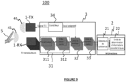
- FIG. 1 represents an example of an operational system 200 in which an ultrasonic sensor 1 is used comprising a set of ultrasonic transducers 10 and a system 100 for processing signals from the transducers 10 of the ultrasonic sensor 1, according to certain embodiments of the invention.
- the set of transducers 10 of the ultrasonic sensor comprises at least two ultrasonic transducers.
- the processing system comprises a coupling device 3 and a pulse processing unit 2.
- the coupling device 3 is configured to couple the transducers 10 of the ultrasonic sensor 1 with the pulse processing unit 2.
- the set of ultrasonic transducers 10 may include a subset of 1-TX transmission transducers and a subset of 1-RX reception transducers. Alternatively, the same transducers 10 can be used in transmission and reception.
- the transducers 10 can for example be MEMS type transducers.
- the ultrasonic transducers 10 of the set of transducers 1 can be located in the same place, which guarantees the compactness of the system.
- the pulse processing unit may comprise a classifier 2 such as an SNN type pulse neural network or a non-event classifier (for example, convolutional neural network or any other classifier).
- a classifier 2 such as an SNN type pulse neural network or a non-event classifier (for example, convolutional neural network or any other classifier).
- non-event classifier refers to any classifier implementing non-event classification, other than a spiking neural network.
- a non-event classifier uses a representation of the data in the form of a sequence of real values rather than in the form of pulses where the information is contained in their number and position.
- Examples of non-event classifiers include, without limitation, formal neural networks (e.g.
- classifiers based on GMM algorithms (acronym for ⁇ Gaussian Mixture model') followed by a Hidden Markov Model (HMM), SVM algorithms (acronym for 'Support Vector Machine (SVM)'), logistic regression algorithms, algorithms based on tree-type models decisions, or even classifiers using predefined rules without learning (not learned automatically).
- GMM Gaussian mixture model
- HMM Hidden Markov Model
- Examples of classifier implementation can be a recurrent neural network, a Gaussian mixture model (GMM) followed by Hidden Markov Model (HMM), or a set of predefined rules without training.
- GMM Gaussian mixture model
- HMM Hidden Markov Model
- Signals are initially sent by the ultrasonic transducers 10. Such signals are ultrasonic in nature. When these signals encounter an object 5 (detected object), echoes are formed and reflected (reflected signals 41) towards the set of transducers 10. The signals reflected 41 by the object 5 and received by the set of transducers 1 ( received signal) are then processed by the processing system 100 to determine characteristic information relating to the detected object, depending on the application of the invention.
- the characteristic information may include, for example, the distance separating the ultrasonic sensor 1 from the object, in an object detection application.
- the processing system 100 is advantageously configured to exploit the fact that the physical signal at the output of the ultrasound transducers 10 is relatively close to what is expected at the input of the pulse processing unit. 2 (SNN neural network for example).
- the processing system 100 can be used in various applications such as for example and without limitation, in object detection (detection of distance and/or angle of detected object), gesture detection, or even for pattern recognition in images formed from ultrasound signals.
- the processing system 100 can be used to determine characteristic information relating to the object detected by carrying out measurements by time of flight or by Doppler effect.
- the propagation of a physical signal is used to characterize an object 5 located at a distance.
- the signals emitted 40 by the ultrasonic sensor 1 encounter an object, the signals reflected 41 by the object (echoes) and received by the transducers 10 can be measured at a later time using suitable signal processing to determine the distance between the source of the signals, corresponding to the set of ultrasonic transducers 10, and the object 5 encountered by the signals emitted, according to a “time of flight” measurement.
- the characteristic information relating to the detected object, determined by the pulse processing unit 2 of the processing system 100 can include the distance d which separates the set 1 of ultrasonic transducers from the detected object.
- the factor 2 present in the denominator of equation (1) takes into account the return and return of the echo, assuming that the transmitter (ultrasonic transducers 10) is close to the receiver (detected object 5).
- c designates the propagation speed of acoustic waves in the medium considered.
- Other distance measurement techniques d can be used by the pulse processing unit 2 to determine the distance information d , such as for example a distance measurement by continuous emission with frequency modulation, or a measurement by FMCW radar.
- the emission of the ultrasonic signal emitted by an ultrasonic sensor 1 can consist of several components at several frequencies.
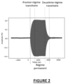
- FIG 2 corresponds to a signal emitted by an ultrasonic transducer 10 excited by an electrical signal at fixed frequency and amplitude.
- the electrical signal is made up of a set of sinusoids, with one and the same frequency, while the ultrasonic signal is made up of a first transient excitation regime (1), a permanent regime (2) and a second transient de-excitation regime (3).
- the regimes (1) and (2) are carried out at a characteristic frequency of the ultrasonic transducer 10, also called 'characteristic frequency' below.
- the characteristic frequency depends on the natural frequency of the transducer 10 and its quality factor.
- the second transient regime (3) presents a sinusoidal signal at the excitation frequency. The difference between the two frequencies of interest is typically a few percent (%).
- the duration of the transient regimes is proportional to the quality factor of the transducer. For example, for a quality factor of 50, 100 cycles are generally necessary to reach steady state (2), which typically corresponds to 1ms for a frequency of around 100 kHz.
- the processing system 100 is advantageously configured to take into account this difference of a few percent (%) and the importance of the transient regime. Indeed, in the particular case of very short ultrasonic signals ( ⁇ 1 ms), the signal is mainly made up of the two transient regimes (1) and (3).
- the frequency of the signal depends on the characteristic frequency of the transducer. It is therefore difficult to produce interference between signals coming from different transducers.
- the coupling device 3 advantageously implements a transformation of the signal into pulses and a thresholding making it possible to be more robust to this frequency dispersion.
- the electrical emission signal from a transducer and the resulting ultrasonic signal can be more complex.
- the limited bandwidth of the ultrasonic transducer 10 means that the ultrasonic signal comprises two transient regimes whose characteristics do not depend only on the emission signal, but also on the specific characteristics of the transducer 10.
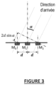
- FIG. 3 illustrates the phase shift as a function of the angle of incidence of the received echo, using three transducers M 0 , M 1 and M 2 .
- the signal arrives with an angle of incidence ⁇ on the set of N transducers (10).
- the difference in distance traveled by the signal to arrive at the transducers M 0 and M 2 , 2d apart, is equal to 2d sin ⁇ .
- the acoustic wave propagates at the speed of sound c.
- the information is contained in the time shift, that is to say in the phase shift of the signal.
- the signals received by the transducers 10 of the ultrasonic sensor 1 are processed by the coupling device 3 and the pulse processing unit 2 to determine the characteristic information(s) relating to an object 5, depending on the application of the 'invention.
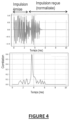
- the characteristic information can for example include information indicating whether an object has been detected or not, or the distance between the sensor 1 and the detected object 5 which can be determined by from the signals received 41 by the transducers 10 by performing a correlation between the received signals and the expected signals (the correlation is maximum for a delay corresponding to the propagation time). It is possible to send an optimized signal whose autocorrelation has low sidelobes to further improve the distance measurement.
- FIG. 4 illustrates the principle of matched filtering correlating the signal emitted by sensor 1 with the signal received by sensor 1.
- the system 100 can be configured to determine characteristic information corresponding to a dynamic characteristic of the object, for example its movement.
- the determination of the characteristic of the object can be carried out by processing several successive static signals, by measuring the distance and the angle for several successive scenes captured by the ultrasonic sensor 1, and by processing such measurements.
- the processing system 100 makes it possible to perform direct, optimized processing by directly providing characteristic information (for example movement from right to left in an application gesture detection), without intermediate information.
- characteristic information for example movement from right to left in an application gesture detection
- the processing system 100 is configured to determine characteristic information (for example detection information such as a direction and distance measurement or gesture detection) using a simplified circuit comprising the coupling device 3 and the processing unit. pulse processing 2.
- characteristic information for example detection information such as a direction and distance measurement or gesture detection
- the signal processing system 100 is configured to process the signals delivered by the ultrasonic transducers 10 of the ultrasonic sensor 1.
- the transducers 10 of the ultrasonic sensor 1 emit signals 40. When these signals reach an object 5, echoes 41 are formed corresponding to the signals reflected 41 by a detected object 5.
- the reflected signals 41 received by N transducers 10 of the ultrasonic sensor 1 are then transmitted to the processing system 100.
- the processing system 100 is configured to process the signals from the N transducers in order to determine at least one characteristic information relating to the detected object 5.
- Each signal from a transducer 10 is received by the coupling device 3 and corresponds to a processing channel in the coupling device 3.
- the coupling device 3 (also called a transformation device) is configured to transform the signals coming from the N transducers 10 of the set of transducers 1 into pulses.
- the pulse processing unit 2 is configured to process the pulses delivered by the coupling device 3 in order to determine at least one characteristic piece of information relating to the detected object.
- the pulse processing unit 2 is configured to determine the characteristic information relating to a detected object 5 from the pulses determined by the coupling device for all the signals coming from the transducers 10.
- the processing system 100 advantageously consumes little energy and ensures coupling between the ultrasonic transducers of the set of transducers 1 and the pulse processing unit 2.
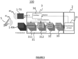
- FIG. 5 represents a system 100 for processing signals from the transducer assembly 1 in which the pulse processing unit 2 comprises a classifier 20 of the pulse neural network type, arranged at the output of the pulse transformation unit 33, according to a first embodiment.
- the impulse neural network 20 is capable of learning on its own an optimal way of adding a delay and combining the different channels associated with the transducers.
- FIG. 5 corresponds to an example of application of the invention to the detection of end-to-end gestures.
- the detection system comprises a set of 1-TX emission transducers comprising a plurality of 10-TX ultrasonic emission transducers configured to emit an ultrasonic signal at a fixed frequency of short duration, such as for example 250 ⁇ s to 100 kHz (acoustic signal).
- a repetition of the measurements can be carried out according to a time interval.
- the time interval can be fixed (for example, a measurement is taken every 10 ms).
- the characteristic information relating to a detected object 5 in the scene of the sensor 1 may include the trajectory of the object.
- the trajectory of the object 5 can then be determined by aggregating the results of the measurements carried out repetitively over a period of time.
- the characteristic information may further include high-level characteristics such as gestures from the determined trajectory.
- the coupling device 3 of the detection system 100 may comprise a pre-processing unit 31 forming a front electronic part ('front-end') comprising a set of amplifiers 311 and/or a set of band-pass filters 312.
- the pre-processing unit 31 is configured to carry out the conversion of the physical signal (charge, voltage, etc.), received from each of the N transducers (10-RX in the example of the figure 5 ) in analog voltage.
- the set of amplifiers 311 comprises at least one amplifier and is configured to amplify the analog voltage thus converted so as to make it more immune to noise likely to be added to the signal.
- the bandpass filter set 312 includes at least one bandpass filter and is configured to filter the voltage (if applicable after amplification by the amplifier set 311) to eliminate out-of-band noise passing.
- the thresholding unit 32 is configured to apply thresholding to the filtered signal delivered by the pre-processing unit 31 (signal derived from the signal coming from each of the N transducers) in order to recover the directional information contained in the phase of the signal filtered using at least one threshold.
- the thresholding unit 32 can be configured to apply thresholding to the signal derived from the signal coming from each of the N transducers of so as to keep only the rising edge of the signal.
- the thresholding unit 32 can be configured to keep only the falling edge or both edges (rising and falling).
- the coupling device 3 thus corresponds to the analog domain, while the pulse processing unit 2 corresponds to the pulse domain and the controller 34 corresponds to a mixed signal domain.
- FIG. 7 illustrates the successive stages of transformation of the signal coming from one of the N transducers (10-RX in the example of the figure 5 ) in pulses containing the phase of the signal while retaining only the rising edge after thresholding, implemented by the coupling device 3, in the example of embodiment of the figure 5 .
- the upper diagram 7A of the Figure 7 represents the signal received from one of the N transducers (10-RX)
- the central diagram 7B of the Figure 7 represents the signal after amplification by the set of amplifiers 311, filtering by the set of bandpass filters 312, and thresholding by the thresholding unit 32.
- the lower diagram 7C of the Figure 7 represents the data obtained after transformation into pulses by the transformation unit 33.
- the coupling device 3 of the processing system 100 may further comprise a controller 34 configured to adapt one or more signal shaping parameters.
- the controller 34 can be configured to adapt the threshold used by the thresholding unit 32 to determine the phase of the signal, according to one or more adaptation criteria such as criteria relating to the distance or the quality of the signal.
- the controller 34 can be configured to adapt the shaping parameters of the signals from the N transducers dynamically or statically.
- the parameter controller 34 may be configured to adapt the threshold used by the thresholding unit 32 based on the distance between the ultrasonic sensor 1 and the detected object 5. For example, the parameter controller 34 can decrease the threshold value during the measurement to adapt it to the decrease in the amplitude of the signal echo with distance.
- the parameter controller 34 can be configured to adapt the value of the threshold according to the quality of previous measurements, calculated in the pulse domain or after real number conversion of the pulse density.
- the threshold used by the thresholding unit 32 to obtain the phase of the signal can be fixed.
- the controller 34 can use information provided by the pulse processing unit 2.
- the pulse processing unit 2 may comprise, in addition to the main classifier, a secondary classifier configured to determine an optimal amplitude for the threshold based on intermediate representations of the information in the transmission chain, in an impulse or non-impulse domain.
- the secondary classifier may determine the threshold magnitude from a set of possible threshold magnitude values.
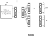
- the secondary classifier may be a secondary spiking neural network (SNN), as illustrated in Figure 1. Figure 8 .
- the coupling device may also comprise at least one coherence detector.
- FIG 8 represents an example of a pulse processing unit 2 comprising a main classifier 20 of the SNN neural network type used to determine the characteristic information relating to a detected object 5, from the pulses received (for example to detect gestures), and a secondary classifier 200, for example of the SNN neural network type, configured to select the threshold to be used by the thresholding unit 32 and transmit the threshold information to the controller 34.
- a main classifier 20 of the SNN neural network type used to determine the characteristic information relating to a detected object 5, from the pulses received (for example to detect gestures)
- a secondary classifier 200 for example of the SNN neural network type, configured to select the threshold to be used by the thresholding unit 32 and transmit the threshold information to the controller 34.
- the controller 34 can further be configured to synchronize the different functional blocks of the processing system 100 in order to implement relevant feedback.
- the controller 34 can in particular be configured to control the moment of sending of the pulses (in transmission) and synchronize the transmission with the reception in order to be able to measure the information of interest (for example the time of flight).
- the controller 34 can further be configured to select a time interval of interest in which echoes from objects located at a chosen distance interval will be received.
- the controller 34 can retrieve information on any functional block, ie on the signal before/after amplification, before/after filtering, before/after thresholding to dynamically adapt detection parameters.
- part of the impulse neural network 20 is dedicated to the choice of an optimal threshold for the measurement per channel.
- the pulse transformation unit 33 is configured to determine a pulse density for each of the N channels corresponding respectively to the N transducers 10 from which the signals processed by the processing system 100 come. The pulse densities thus determined can be used as input to the pulse processing unit 2.
- the pulse processing unit 2 comprises a main classifier 20 (for example, pulse neural network) for determining classification information from the pulses delivered by the coupling device 3, i.e. without having to go through an intermediate representation of the data.
- the characteristic information relating to a detected object 5 includes classification information, for example such as end-to-end gesture classification information in the embodiment. of the figure 5 .
- the non-event classifier takes as input the signal, which can be processed beforehand by a post-filtering block, in the form of a vector per frame .
- the classifier 20 makes a decision on the nature of the gesture based on the frame and the previous frames and potentially the following frames over a certain window.
- FIG. 9 represents a processing system 100, according to a second embodiment.
- the components 31, 32, 33, and 34 of the treatment system 100 are similar to those described with reference to the figure 5 corresponding to the first embodiment.
- the processing system 100 according to the second embodiment differs from the first embodiment, shown in the figure. figure 5 , in that the pulse processing unit 2 comprises, instead of the pulse classifier 20, a set of coherence detectors 21 comprising at least one coherence detector, followed by a unit for determining characteristic information 22.
- the characteristic information determination unit 22 is configured to determine at least one characteristic information relating to an object detected 5 by the ultrasonic sensor 1 (for example distance and/or direction of the echo(es) coming from different objects in the scene captured by the ultrasonic sensor 1).
- the set of coherence detectors 21 exploits the directions of incidence of the echoes coming from the different objects in the scene captured by the ultrasound sensor 1.
- the set of coherence detectors 21 is configured to provide in parallel coherence information for M directions from the N channels corresponding respectively to the N transducers.
- the output of a coherence detector 21 has a certain pulse density at a time t depending on whether the signals received in this direction are coherent.
- the set of coherence detectors 21 thus detect whether the signals received in a direction are or not consistent.
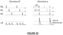
- a coherence detector 21 may comprise a leaky integrator LIF for measuring the alignment of the edges of the signals corresponding to the N respective channels corresponding to the N transducers.
- a leak integrator ascronym for “Leaky Integrator and Fire”
- the LIF output y n takes the value 1, which means that coherence is detected between the signals corresponding to the N channels for a given direction.
- LIF can also be performed in continuous time with an analog implementation, following a similar operating principle. Equation (3) is then replaced by a time-function equation instead of being a recurrence equation.
- the set of coherence detectors 21 has the advantage of being able to operate even if the different signals to be compared (signals corresponding to the N channels) have different amplitudes, which is the case if the signal is in transient mode or if the transducers 10 are different from each other. Such coherence detection processing is therefore robust to a certain technological variability.
- the set of coherence detectors 21 operates even if the signals do not have exactly the same frequency, for example in transient conditions.
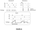
- the set of coherence detectors 21 may comprise a windowing unit configured to apply windowing, instead of a LIF to detect the coherence between the signals from the received pulses.
- Coherence detection by windowing consists of counting the number of pulses, among all the N input channels contained, in a small width window. Similar to the embodiment in which the coherence detectors use a LIF, a coherence threshold can be used to detect coherence between the signals corresponding to the N channels for a given direction. The coherence threshold is then applied to the number of pulses detected in the window which starts with the first pulse.
- FIG. 11 illustrates a coherence detection implemented by the coherence detector assembly 21 using windowing, according to such an embodiment.
- a window is applied to the detection of each rising edge.
- the coherence detector assembly 21 provides an output in the form of a plurality of series of pulses.
- the pulses can be directly supplied to a pulse-type classifier 20 (SNN). If the classifier 20 is a non-event classifier type classifier, the pulses are converted into pulse density before being transmitted to the classifier 20.
- the conversion can be carried out using a post-processing block comprising a pass filter. low or a counter to count the number of pulses per time interval (for example 10 ms). The greater the density of the pulses determined by the coupling device 2 at a given instant, the more coherence there is in the signals coming from the transducers 10 of the ultrasonic sensor 1.
- the characteristic information determination unit 22 may be configured to determine the direction of the main echo(es) from the output of the coherence detector, as shown in FIG. Figure 12 .
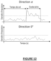
- FIG. 12 illustrates the density of the pulses delivered by the set of coherence detectors 21 as a function of time, in an echo direction(s) of angle ⁇ (upper diagram), and in an echo direction(s) of angle 0° (bottom diagram). There Figure 12 highlights flight time for distance measurement.
- An echo coming from a particular direction results in a stronger pulse density on the output corresponding to the direction of the echo than on the outputs corresponding to the other possible directions.
- the direction(s) of arrival of the echoes can be determined.
- FIG. 12 also illustrates the principle of distance measurement. Using the same information as for the direction, the distance measurement can be carried out at the output of the set of coherence detectors 21 by applying a pulse density threshold to the pulse density, and by calculating the distance in using equation (1).
- FIG 13 represents a processing system 100, according to a third embodiment.
- the processing system 100 according to the third embodiment is similar to the processing system, according to the second embodiment shown on the Figure 9 , and similarly uses a set of coherence detectors 21. However, it also uses a classifier 20 of the impulse neural network type configured to provide classification information from the pulses delivered by the set of coherence detectors. Such a classifier 20 is configured to receive the series of pulses delivered by the coherence detector assembly 21.
- the characteristic information determination unit 22 of the detection system 100 according to the second embodiment ( Figure 9 ) is thus replaced in the third embodiment by the classifier 20.
- FIG. 14 represents a processing system 100, according to a fourth embodiment.
- the processing system 100 according to the fourth embodiment is similar to the processing system, according to the third embodiment shown on the Figure 9 , and also uses a set of coherence detectors 21. However, it additionally uses a classifier 20 of the non-event classifier type, configured to provide classification information from the pulses delivered by the set of coherence detectors 21, preceded by a post-processing block 23.
- the post-processing block 23 is configured to convert the pulses into pulse density before being transmitted to the non-event classifier 20.
- the post-processing block 23 may include a low-pass filter at the output of the coherence detector assembly 21 to provide an image of the pulse density, rather than a series of pulses, and a sampling unit to sample the low-frequency signal provided at the output of the low-pass filter to carry out data processing.
- the post-processing block 23 may include an asynchronous counter arranged at the output of the set of coherence detectors 21 to count the pulses and sample the output of the set of coherence detectors with a clock signal.
- FIG. 15 represents a processing system 100, according to a fifth embodiment.
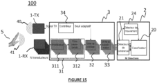
- the processing system 100 according to the fifth embodiment is similar to the processing system of the third embodiment shown in the Figure 13 , and uses in an identical manner a set of coherence detectors 21.
- This fifth embodiment corresponds to an application of the invention to gesture detection.
- the processing system 100 according to the fifth embodiment further comprises a motion detector 24 to optimize consumption.
- the processing system 100 according to the fifth embodiment is in particular configured to be activated only when a movement is detected by the movement detector 24. This makes it possible to avoid activating gesture detection in the absence of movement. In fact, the most of the time, there is no movement in front of sensor 1 in the area of interest (scene observed by sensor 1) so that it is not necessary in this case to determine which gesture was performed .
- the classifier 20 can be arranged directly on the output of the pulse transformation unit 33 or at the output of the set of coherence detectors 21, as shown in the Figure 15 . In the example of the Figure 15 , the classifier 20 can then perform a classification to detect a gesture only when a movement is detected by the motion detector.
- the output of the set of coherence detectors 21 can be represented by a matrix B of dimensions T ⁇ N ⁇ K with T the number of measurements or frames, N the number of samples per frame (time axis on the Figure 12 ), and K the number of directions analyzed in the set of coherence detectors 21.
- the elements of matrix B are denoted b i,j,k .
- the number of directions K is less than or equal to the total number of directions M.
- the elements of matrix B correspond to the pulse density in an interval [t, t+t frame ] with t frame designating the length of a frame.
- the motion detector 24 then uses the elements of the matrix B.
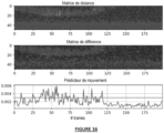
- Motion can be quantified by examining the difference between two successive frames on the distance matrix.
- FIG. 16 illustrates the calculation of a motion predictor on real data (distance matrix, frame-by-frame differentiation and motion detection). In the example of the Figure 16 , it can be observed on the distance matrix a movement from frame 0 to 120, then no movement thereafter. By comparing the motion predictor with a threshold, a signal is obtained which can be used by the gesture detector 25 to determine a gesture classification.
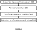
- FIG. 17 illustrates the method of processing signals from a set of transducers, according to certain embodiments.
- step 600 at least some of the transducers of the set of transducers emit signals and/or receive echoes corresponding to the reflection of the signals by a detected object 5.
- steps 602 and 604 a step of transforming the signals received from at least certain transducers of the set of transducers into pulses is implemented.
- step 602 for each signal received by one of the N transducers 10, thresholding is applied to a signal derived from the signal received from the transducer so as to extract directional information contained in the phase of the derived signal, using at least one threshold, the extracted information comprising the rising and/or falling edges of the derived signal.
- step 604 the signal derived from the signal received from the transducer is transformed into pulses containing the phase of the signal, using the signal edge(s) extracted in the step of applying thresholding.
- step 606 a step of processing the pulses obtained is implemented, the step of processing the pulses comprising the determination of the characteristic information from the pulses determined for all the signals received from the transducers.
- the determined characteristic information can then be delivered for additional processing, or to generate a display of this information. Alternatively, an action can be triggered based on the determined characteristic information.
- the embodiments of the invention make it possible to detect objects, gestures or even dynamic characteristics of objects.
- the set of transducers 1 can be a 2D matrix.
- Each transducer 10 of the set of transducers 1 sends a pulse, which is returned if the transducer 10 is located facing a “hollow” of the hand, and which is transmitted if the transducer is located facing the skin.
- the set of returned pulses is used to form an image (at what level of the processing chain?), which is then processed by the processing system 100.
- the embodiments of the invention thus allow direct coupling of the ultrasonic transducers 10 to a pulse processing unit 2 (comprising for example a neural network) making it possible to directly determine the characteristic information(s), depending on the application of the invention.
- the processing system 100 is advantageously configured to improve the angular resolution compared to the ultrasonic transducer systems of the state of the art.
- the processing system 100 is configured to make it possible to reduce the blind zone of the transducer system, to reduce the complexity of the processing, and to provide robustness to the dispersion in characteristic of the transducers 10 of the set of transducers 1, while having a certain compactness (all of the transducers 10 are located in the same place) and providing quality angular information.
- processing device 100 or subsystems of the device can be implemented in various ways by hardware, software, or a combination of hardware and software, especially in the form of program code capable of being distributed as a program product, in various forms.
- program code may be distributed using computer-readable media, which may include computer-readable storage media and communications media.
- the methods described in the present description may in particular be implemented in the form of computer program instructions executable by one or more processors in a computer computing device. These Computer program instructions may also be stored in computer-readable media.
- the processing system 100 can be used to provide images obtained by ultrasound representing the echoes received by a set of ultrasound transducers. In certain cases, not only the first echo, but also the following echoes can be represented. Image processing makes it possible to extract the detection information defined according to the biomedical application (for example, neck thickness). The information provided can then be used to assist in medical diagnosis.
- the embodiments make it possible to simplify image reconstruction processing of ultrasound systems outside laboratories.
Landscapes
- Engineering & Computer Science (AREA)
- Physics & Mathematics (AREA)
- Radar, Positioning & Navigation (AREA)
- Remote Sensing (AREA)
- General Physics & Mathematics (AREA)
- Computer Networks & Wireless Communication (AREA)
- Acoustics & Sound (AREA)
- Multimedia (AREA)
- General Engineering & Computer Science (AREA)
- Theoretical Computer Science (AREA)
- Human Computer Interaction (AREA)
- Measurement Of Velocity Or Position Using Acoustic Or Ultrasonic Waves (AREA)
- Investigating Or Analyzing Materials By The Use Of Ultrasonic Waves (AREA)
Claims (17)
- System (100) zur Verarbeitung von Signalen, die von einem Ultraschallsensor (1) geliefert werden, wobei der Ultraschallsensor einen Satz von Wandlern (10) umfasst, wobei mindestens einige der Wandler des Satzes von Wandlern dafür konfiguriert sind, Signale auszusenden und/oder der Reflexion der Signale von einem erkannten Objekt (5) entsprechende Echos zu empfangen, wobei als Reaktion auf den Empfang von Echos durch die Wandler Signale von einer Vielzahl von Wandlern des Ultraschallsensors an das Verarbeitungssystem (100) übertragen werden, wobei das Verarbeitungssystem dafür konfiguriert ist, mindestens eine charakteristische Information betreffend das erkannte Objekt anhand der von den Wandlern des Ultraschallsensors empfangenen Signale zu bestimmen, dadurch gekennzeichnet, dass es eine Kopplungsvorrichtung (3) umfasst, die dafür konfiguriert ist, die von mindestens einigen Wandlern des Satzes von Wandlern empfangenen Signale in Impulse umzuwandeln, und eine Impulsverarbeitungseinheit (2), die dafür konfiguriert ist, die von der Kopplungsvorrichtung gelieferten Impulse zu verarbeiten, und dadurch, dass die Kopplungsvorrichtung Folgendes umfasst:- eine Schwellenwertbildungseinheit (32), die dafür konfiguriert ist, für jedes von einem Wandler empfangene Signal eine Schwellenwertbildung auf ein von dem von dem Wandler empfangenen Signal abgeleitetes Signal anzuwenden, um unter Verwendung mindestens eines Schwellenwertes eine Richtungsinformation, die in der Phase des abgeleiteten Signals enthalten ist, zu extrahieren, wobei die extrahierte Information die steigenden und/oder fallenden Flanken des abgeleiteten Signals umfasst;- eine Einheit zum Umwandeln eines Signals in Impulse (33), die dafür konfiguriert ist, unter Verwendung der einen oder der mehreren Signalflanken, die von der Schwellenwertbildungseinheit (32) extrahiert werden, das von dem von dem Wandler empfangenen Signal abgeleitete Signal in Impulse umzuwandeln, die die Phase des Signals enthalten;wobei die Impulsverarbeitungseinheit (2) dafür konfiguriert ist, mindestens eine charakteristische Information betreffend das erkannte Objekt anhand der von der Kopplungsvorrichtung bestimmten Impulse für alle von den Wandlern empfangenen Signale zu bestimmen.
- System nach Anspruch 1, dadurch gekennzeichnet, dass die Impulsverarbeitungseinheit (2) mindestens einen Klassifizierer (20) umfasst.
- System nach Anspruch 2, dadurch gekennzeichnet, dass der mindestens eine Klassifizierer einen Hauptklassifizierer umfasst, wobei der Hauptklassifizierer ein Klassifizierer eines gepulsten neuronalen Netzes (20) oder ein nicht ereignisgetriebener Klassifizierer ist.
- System nach einem der Ansprüche 2 und 3, dadurch gekennzeichnet, dass der mindestens eine Klassifizierer (20) ferner einen sekundären Klassifizierer (200) umfasst, um aus einem Satz von möglichen Schwellenamplitudenwerten anhand der von der Kopplungsvorrichtung empfangenen Impulse die Amplitude des Schwellenwertes zu bestimmen, die von der Schwellenwertbildungseinheit (32) verwendet wird.
- System nach einem der vorhergehenden Ansprüche, dadurch gekennzeichnet, dass es ferner einen Satz von Verstärkern (311) umfasst, wobei der Satz von Verstärkern (311) mindestens einen Verstärker umfasst und dafür konfiguriert ist, die analoge Spannung jedes von dem Wandler empfangenen Signals zu verstärken.
- System nach Anspruch 5, dadurch gekennzeichnet, dass es ferner einen Satz von Bandpassfiltern (312) umfasst, wobei der Satz von Bandpassfiltern (312) mindestens ein Bandpassfilter umfasst und dafür konfiguriert ist, die von dem Satz von Verstärkern (311) verstärkte Spannung so zu filtern, dass das Rauschen außerhalb des Passbandes eliminiert wird, wobei das von jedem von dem Wandler empfangenen Signal abgeleitete Signal das von dem Satz von Bandpassfiltern gelieferte Signal ist.
- System nach einem der vorhergehenden Ansprüche, dadurch gekennzeichnet, dass es eine Steuerung (34) umfasst, die dafür konfiguriert ist, einen oder mehrere Parameter zum Formen der von den Wandlern (10) empfangenen Signale in Abhängigkeit von einem oder mehreren Anpassungskriterien unter Verwendung von von der Impulsverarbeitungseinheit (2) stammenden Signalen anzupassen.
- System nach Anspruch 7, dadurch gekennzeichnet, dass die Steuerung (34) dafür konfiguriert ist, den von der Schwellenwertbildungseinheit (32) verwendeten Schwellenwert in Abhängigkeit von dem Abstand zwischen dem Ultraschallsensor (1) und dem Objekt oder in Abhängigkeit von der Qualität von vorherigen, von dem Ultraschallsensor (1) ausgeführten Messungen anzupassen, wobei die Qualität in dem Impulsbereich oder nach einem Umwandeln der Impulsdichte in eine reelle Zahl berechnet wird.
- System nach einem der Ansprüche 5 bis 8, dadurch gekennzeichnet, dass die Impulsverarbeitungseinheit (2) einen Satz von Kohärenzdetektoren (21) umfasst, die mindestens einen Kohärenzdetektor und eine Einheit zum Bestimmen von charakteristischen Informationen (2) umfasst, wobei der Satz der Kohärenzdetektoren (21) dafür konfiguriert ist, für eine gegebene Richtung der von dem Objekt stammenden Echos anhand der von der Einheit zum Umwandeln in Impulse (33) gelieferten Impulse zu erkennen, ob die von den Wandlern stammenden Signale kohärent sind, und die Impulse an die Einheit zum Bestimmen von charakteristischen Informationen (2) zu liefern, wenn eine Kohärenz erkannt wird.
- System nach Anspruch 9, dadurch gekennzeichnet, dass die Einheit zum Bestimmen der charakteristischen Informationen eine Einheit (23) zum Messen des Abstands und/oder der Richtung der von dem Objekt stammenden Echos ist.
- System nach Anspruch 10, dadurch gekennzeichnet, dass die Einheit zum Bestimmen von charakteristischen Informationen ein Klassifizierer (24) ist.
- System nach einem der Ansprüche 9 und 10, dadurch gekennzeichnet, dass ein Kohärenzdetektor (21) einen Leckintegrator umfasst, um eine Ausrichtung der Flanken der Signale, die von den Wandlern (10) des Satzes von Wandlern (1) empfangen werden, zu messen.
- System nach einem der Ansprüche 9 und 10, dadurch gekennzeichnet, dass ein Kohärenzdetektor (21) eine Befensterungseinheit umfasst, die dafür konfiguriert ist, anhand der von der Kopplungsvorrichtung gelieferten Impulse eine Befensterung zum Erkennen einer Kohärenz zwischen den von den Wandlern empfangenen Signalen anzuwenden, wobei die Befensterungseinheit dafür konfiguriert ist, die Anzahl an Impulsen unter allen Übertragungskanälen entsprechend den verschiedenen Wandlern des Satzes von Wandlern (1) in einem Fenster einer gegebenen Breite zu zählen.
- System nach einem der Ansprüche 9 bis 13, dadurch gekennzeichnet, dass es ferner ein Tiefpassfilter am Ausgang des Satzes von Kohärenzdetektoren (21), die dafür konfiguriert sind, ein Bild der Dichte der von dem Satz von Kohärenzdetektoren gelieferten Impulse bereitzustellen, und eine Abtasteinheit umfasst, die dafür konfiguriert ist, das von dem Tiefpassfilter empfangene Niederfrequenzsignal abzutasten.
- System nach einem der Ansprüche 9 bis 13, dadurch gekennzeichnet, dass es ferner einen asynchronen Zähler umfasst, der am Ausgang des Satzes von Kohärenzdetektoren angeordnet ist, der dafür konfiguriert ist, die Impulse zu zählen und den Ausgang des Satzes von Kohärenzdetektoren mit einem Taktsignal abzutasten.
- System nach einem der Ansprüche 9 bis 13, dadurch gekennzeichnet, dass es ferner einen Bewegungsdetektor (24) umfasst, der am Ausgang des Satzes von Kohärenzdetektoren angeordnet ist, um das Vorliegen einer Bewegung in der von dem Ultraschallsensor (1) überwachten Zone zu erkennen.
- Verfahren zur Verarbeitung von Signalen, die von einem Ultraschallsensor (1) geliefert werden, wobei der Ultraschallsensor einen Satz von Wandlern umfasst, wobei mindestens einige der Wandler des Satzes von Wandlern Signale aussenden und/oder der Reflexion der Signale von einem erkannten Objekt entsprechende Echos empfangen, wobei das Verfahren das Bestimmen mindestens einer charakteristischen Information betreffend das erkannte Objekt anhand der von den Wandlern des Ultraschallsensors empfangenen Signale umfasst, dadurch gekennzeichnet, dass das Verfahren einen Schritt zum Umwandeln der von mindestens einigen Wandlern des Satzes von Wandlern empfangenen Signale in Impulse und einen Schritt zum Verarbeiten der Impulse umfasst, wobei der Umwandlungsschritt für jedes von einem Wandler empfangene Signal Folgendes umfasst:- Anwenden einer Schwellenwertbildung auf ein von dem von dem Wandler empfangenen Signal abgeleitetes Signal, um eine Richtungsinformation, die in der Phase des abgeleiteten Signals enthalten ist, unter Verwendung von mindestens eines Schwellenwertes zu extrahieren, wobei die extrahierte Information die steigenden und/oder fallenden Flanken des abgeleiteten Signals umfasst;- Umwandeln des von dem von dem Wandler empfangenen Signal abgeleiteten Signals in Impulse, die die Phase des Signals enthalten, unter Verwendung der einen oder der mehreren Signalflanken, die in dem Schritt des Anwendens einer Schwellenwertbildung extrahiert werden;und dadurch, dass der Schritt zum Verarbeiten der Impulse (2) das Bestimmen der charakteristischen Informationen anhand der für alle von den Wandlern empfangenen Signale bestimmten Impulse umfasst.
Applications Claiming Priority (1)
| Application Number | Priority Date | Filing Date | Title |
|---|---|---|---|
| FR2104297A FR3122261B1 (fr) | 2021-04-26 | 2021-04-26 | Dispositif et procédé de traitement du signal issus d’un ensemble de transducteurs ultrasonores |
Publications (2)
| Publication Number | Publication Date |
|---|---|
| EP4083659A1 EP4083659A1 (de) | 2022-11-02 |
| EP4083659B1 true EP4083659B1 (de) | 2024-02-07 |
Family
ID=76730723
Family Applications (1)
| Application Number | Title | Priority Date | Filing Date |
|---|---|---|---|
| EP22169557.0A Active EP4083659B1 (de) | 2021-04-26 | 2022-04-22 | Vorrichtung und verfahren zur verarbeitung von signalen aus einer gesamtheit von ultraschallwandlern |
Country Status (5)
| Country | Link |
|---|---|
| US (1) | US11960036B2 (de) |
| EP (1) | EP4083659B1 (de) |
| JP (1) | JP2022168855A (de) |
| CN (1) | CN115248435A (de) |
| FR (1) | FR3122261B1 (de) |
Families Citing this family (3)
| Publication number | Priority date | Publication date | Assignee | Title |
|---|---|---|---|---|
| JP7559570B2 (ja) * | 2021-01-22 | 2024-10-02 | 株式会社Soken | 物体検知装置 |
| WO2022250703A1 (en) * | 2021-05-28 | 2022-12-01 | Google Llc | Hand-grip location detection using ultrasound |
| CN119921794B (zh) * | 2024-12-27 | 2025-10-28 | 中国航空无线电电子研究所 | 一种tcn、atc一体化信号识别方法 |
Family Cites Families (9)
| Publication number | Priority date | Publication date | Assignee | Title |
|---|---|---|---|---|
| JP2930678B2 (ja) * | 1990-07-18 | 1999-08-03 | 古野電気株式会社 | サイドルッキングソナー |
| DE10164030A1 (de) * | 2001-12-28 | 2003-07-17 | Grieshaber Vega Kg | Verfahren und Schaltungsanordnung zum Messen der Entfernung eines Gegenstandes |
| US6927699B2 (en) * | 2002-12-05 | 2005-08-09 | Denso Corporation | Object recognition apparatus for vehicle, and inter-vehicle distance control unit |
| JP4283170B2 (ja) * | 2003-12-17 | 2009-06-24 | 株式会社デンソー | 物体検出装置 |
| US8265191B2 (en) * | 2006-04-19 | 2012-09-11 | Zebra Enterprise Solutions Corp. | Receiver for object locating and tracking systems and related methods |
| DE102010062983A1 (de) * | 2010-12-14 | 2012-06-14 | Robert Bosch Gmbh | Verfahren und Vorrichtung zur akustischen Abtastung eines Bereichs |
| US11125866B2 (en) * | 2015-06-04 | 2021-09-21 | Chikayoshi Sumi | Measurement and imaging instruments and beamforming method |
| US10528147B2 (en) * | 2017-03-06 | 2020-01-07 | Microsoft Technology Licensing, Llc | Ultrasonic based gesture recognition |
| JP7559570B2 (ja) * | 2021-01-22 | 2024-10-02 | 株式会社Soken | 物体検知装置 |
-
2021
- 2021-04-26 FR FR2104297A patent/FR3122261B1/fr not_active Expired - Fee Related
-
2022
- 2022-04-22 EP EP22169557.0A patent/EP4083659B1/de active Active
- 2022-04-22 US US17/727,539 patent/US11960036B2/en active Active
- 2022-04-25 JP JP2022071591A patent/JP2022168855A/ja active Pending
- 2022-04-26 CN CN202210465771.2A patent/CN115248435A/zh active Pending
Also Published As
| Publication number | Publication date |
|---|---|
| JP2022168855A (ja) | 2022-11-08 |
| FR3122261A1 (fr) | 2022-10-28 |
| US20220342062A1 (en) | 2022-10-27 |
| EP4083659A1 (de) | 2022-11-02 |
| CN115248435A (zh) | 2022-10-28 |
| US11960036B2 (en) | 2024-04-16 |
| FR3122261B1 (fr) | 2023-03-24 |
Similar Documents
| Publication | Publication Date | Title |
|---|---|---|
| EP4083659B1 (de) | Vorrichtung und verfahren zur verarbeitung von signalen aus einer gesamtheit von ultraschallwandlern | |
| EP2955542B1 (de) | Lidar-doppler zur relativen geschwindigkeitsmessung | |
| EP2440140B1 (de) | Methode und ultraschallgerät zur characterisierung eines mediums | |
| FR3034975A1 (de) | ||
| US11175392B2 (en) | Model-based image reconstruction method | |
| FR2993362A1 (fr) | Procede de traitement de signaux issus d'une acquisition par sondage ultrasonore, programme d'ordinateur et dispositif de sondage a ultrasons correspondants | |
| WO2021023933A1 (fr) | Procédé et système de caractérisation ultrasonore non invasive d'un milieu hétérogène | |
| WO2015177172A1 (fr) | Contraintes conjointes de transitivite de differences temporelles et effet dopler multibandes pour la separation, caracterisation, et localisation de sources sonores par acoustique passive | |
| EP3771927A1 (de) | Ultraschallsystem zum erkennen eines fluidstroms in einem milieu | |
| EP2544020B1 (de) | Verfahren und Vorrichtung zur Detektion eines Ziels, das von starken Energiereflektoren maskiert wird | |
| FR3046693A1 (de) | ||
| EP2720066B1 (de) | Schätzverfahren des Queranteils der Luftgeschwindigkeit bei einer Lidar-Doppler-Messung | |
| US20060235635A1 (en) | Apparatus and method for performing the delay estimation of signals propagating through an environment | |
| FR3065079B1 (fr) | Procede et dispositif de sondage ultrasonore pour l'obtention de courbes de dispersion d'un milieu sonde | |
| EP2453251A1 (de) | Verfahren zum Durchfüren einer hochauflösenden Analyse einer Raumzone mittels einer frequenzbeweglichen Pulswelle | |
| EP0825453B1 (de) | Verfahren und Anordnung zur Bearbeitung von Signalen, welche durch ein Volumenstruktur reflektierte oder übertragene Wellen darstellen, um eine Forschung und Analyse der Struktur auszuführen | |
| EP3044580B1 (de) | Verfahren zur zerstörungsfreien ultraschallprüfung eines bauteils mittels echoanalyse | |
| EP4574056A1 (de) | Verfahren zur charakterisierung eines zielobjekts in einem medium | |
| FR3075373A1 (fr) | Dispositif, installation et procede d'imagerie de defauts d'une structure par emission et reception d'ondes mecaniques dans cette structure | |
| EP4189380B1 (de) | Verfahren zur erkennung von diskontinuitäten und system zur implementierung dieses verfahrens | |
| WO2023152434A1 (fr) | Procédé de reconstruction d'une image d'une scène | |
| EP3470871A1 (de) | Radarsignal-detektionsverfahren | |
| EP2929343B1 (de) | Vorrichtung und verfahren zur ultraschalllbildgebeung mit filterung von artefakten aufgrund von interferenzen zwischen rekonstruktionsmoden | |
| FR3030721A1 (fr) | Dispositif et procede de detection de poissons dans un dispositif de franchissement | |
| FR3113739A1 (fr) | Procédé et dispositif de suivi adaptatif d'un objet basés sur la technologie LIDAR |
Legal Events
| Date | Code | Title | Description |
|---|---|---|---|
| PUAI | Public reference made under article 153(3) epc to a published international application that has entered the european phase |
Free format text: ORIGINAL CODE: 0009012 |
|
| STAA | Information on the status of an ep patent application or granted ep patent |
Free format text: STATUS: REQUEST FOR EXAMINATION WAS MADE |
|
| 17P | Request for examination filed |
Effective date: 20220422 |
|
| AK | Designated contracting states |
Kind code of ref document: A1 Designated state(s): AL AT BE BG CH CY CZ DE DK EE ES FI FR GB GR HR HU IE IS IT LI LT LU LV MC MK MT NL NO PL PT RO RS SE SI SK SM TR |
|
| REG | Reference to a national code |
Ref country code: DE Free format text: PREVIOUS MAIN CLASS: G01S0007520000 Ref country code: DE Ref legal event code: R079 Ref document number: 602022001838 Country of ref document: DE Free format text: PREVIOUS MAIN CLASS: G01S0007520000 Ipc: G01S0015890000 |
|
| GRAP | Despatch of communication of intention to grant a patent |
Free format text: ORIGINAL CODE: EPIDOSNIGR1 |
|
| STAA | Information on the status of an ep patent application or granted ep patent |
Free format text: STATUS: GRANT OF PATENT IS INTENDED |
|
| RIC1 | Information provided on ipc code assigned before grant |
Ipc: G01S 7/527 20060101ALI20230821BHEP Ipc: G01S 7/539 20060101ALI20230821BHEP Ipc: G01S 15/42 20060101ALI20230821BHEP Ipc: G01S 7/52 20060101ALI20230821BHEP Ipc: G01S 15/89 20060101AFI20230821BHEP |
|
| INTG | Intention to grant announced |
Effective date: 20230907 |
|
| GRAS | Grant fee paid |
Free format text: ORIGINAL CODE: EPIDOSNIGR3 |
|
| GRAA | (expected) grant |
Free format text: ORIGINAL CODE: 0009210 |
|
| STAA | Information on the status of an ep patent application or granted ep patent |
Free format text: STATUS: THE PATENT HAS BEEN GRANTED |
|
| AK | Designated contracting states |
Kind code of ref document: B1 Designated state(s): AL AT BE BG CH CY CZ DE DK EE ES FI FR GB GR HR HU IE IS IT LI LT LU LV MC MK MT NL NO PL PT RO RS SE SI SK SM TR |
|
| REG | Reference to a national code |
Ref country code: GB Ref legal event code: FG4D Free format text: NOT ENGLISH |
|
| REG | Reference to a national code |
Ref country code: CH Ref legal event code: EP |
|
| REG | Reference to a national code |
Ref country code: IE Ref legal event code: FG4D Free format text: LANGUAGE OF EP DOCUMENT: FRENCH |
|
| REG | Reference to a national code |
Ref country code: DE Ref legal event code: R096 Ref document number: 602022001838 Country of ref document: DE |
|
| REG | Reference to a national code |
Ref country code: LT Ref legal event code: MG9D |
|
| REG | Reference to a national code |
Ref country code: NL Ref legal event code: MP Effective date: 20240207 |
|
| PG25 | Lapsed in a contracting state [announced via postgrant information from national office to epo] |
Ref country code: IS Free format text: LAPSE BECAUSE OF FAILURE TO SUBMIT A TRANSLATION OF THE DESCRIPTION OR TO PAY THE FEE WITHIN THE PRESCRIBED TIME-LIMIT Effective date: 20240607 |
|
| PG25 | Lapsed in a contracting state [announced via postgrant information from national office to epo] |
Ref country code: LT Free format text: LAPSE BECAUSE OF FAILURE TO SUBMIT A TRANSLATION OF THE DESCRIPTION OR TO PAY THE FEE WITHIN THE PRESCRIBED TIME-LIMIT Effective date: 20240207 |
|
| PG25 | Lapsed in a contracting state [announced via postgrant information from national office to epo] |
Ref country code: GR Free format text: LAPSE BECAUSE OF FAILURE TO SUBMIT A TRANSLATION OF THE DESCRIPTION OR TO PAY THE FEE WITHIN THE PRESCRIBED TIME-LIMIT Effective date: 20240508 |
|
| REG | Reference to a national code |
Ref country code: AT Ref legal event code: MK05 Ref document number: 1655730 Country of ref document: AT Kind code of ref document: T Effective date: 20240207 |
|
| PG25 | Lapsed in a contracting state [announced via postgrant information from national office to epo] |
Ref country code: HR Free format text: LAPSE BECAUSE OF FAILURE TO SUBMIT A TRANSLATION OF THE DESCRIPTION OR TO PAY THE FEE WITHIN THE PRESCRIBED TIME-LIMIT Effective date: 20240207 Ref country code: RS Free format text: LAPSE BECAUSE OF FAILURE TO SUBMIT A TRANSLATION OF THE DESCRIPTION OR TO PAY THE FEE WITHIN THE PRESCRIBED TIME-LIMIT Effective date: 20240507 Ref country code: NL Free format text: LAPSE BECAUSE OF FAILURE TO SUBMIT A TRANSLATION OF THE DESCRIPTION OR TO PAY THE FEE WITHIN THE PRESCRIBED TIME-LIMIT Effective date: 20240207 |
|
| PG25 | Lapsed in a contracting state [announced via postgrant information from national office to epo] |
Ref country code: ES Free format text: LAPSE BECAUSE OF FAILURE TO SUBMIT A TRANSLATION OF THE DESCRIPTION OR TO PAY THE FEE WITHIN THE PRESCRIBED TIME-LIMIT Effective date: 20240207 |
|
| PG25 | Lapsed in a contracting state [announced via postgrant information from national office to epo] |
Ref country code: AT Free format text: LAPSE BECAUSE OF FAILURE TO SUBMIT A TRANSLATION OF THE DESCRIPTION OR TO PAY THE FEE WITHIN THE PRESCRIBED TIME-LIMIT Effective date: 20240207 |
|
| PG25 | Lapsed in a contracting state [announced via postgrant information from national office to epo] |
Ref country code: RS Free format text: LAPSE BECAUSE OF FAILURE TO SUBMIT A TRANSLATION OF THE DESCRIPTION OR TO PAY THE FEE WITHIN THE PRESCRIBED TIME-LIMIT Effective date: 20240507 Ref country code: NO Free format text: LAPSE BECAUSE OF FAILURE TO SUBMIT A TRANSLATION OF THE DESCRIPTION OR TO PAY THE FEE WITHIN THE PRESCRIBED TIME-LIMIT Effective date: 20240507 Ref country code: NL Free format text: LAPSE BECAUSE OF FAILURE TO SUBMIT A TRANSLATION OF THE DESCRIPTION OR TO PAY THE FEE WITHIN THE PRESCRIBED TIME-LIMIT Effective date: 20240207 Ref country code: LT Free format text: LAPSE BECAUSE OF FAILURE TO SUBMIT A TRANSLATION OF THE DESCRIPTION OR TO PAY THE FEE WITHIN THE PRESCRIBED TIME-LIMIT Effective date: 20240207 Ref country code: IS Free format text: LAPSE BECAUSE OF FAILURE TO SUBMIT A TRANSLATION OF THE DESCRIPTION OR TO PAY THE FEE WITHIN THE PRESCRIBED TIME-LIMIT Effective date: 20240607 Ref country code: HR Free format text: LAPSE BECAUSE OF FAILURE TO SUBMIT A TRANSLATION OF THE DESCRIPTION OR TO PAY THE FEE WITHIN THE PRESCRIBED TIME-LIMIT Effective date: 20240207 Ref country code: GR Free format text: LAPSE BECAUSE OF FAILURE TO SUBMIT A TRANSLATION OF THE DESCRIPTION OR TO PAY THE FEE WITHIN THE PRESCRIBED TIME-LIMIT Effective date: 20240508 Ref country code: FI Free format text: LAPSE BECAUSE OF FAILURE TO SUBMIT A TRANSLATION OF THE DESCRIPTION OR TO PAY THE FEE WITHIN THE PRESCRIBED TIME-LIMIT Effective date: 20240207 Ref country code: ES Free format text: LAPSE BECAUSE OF FAILURE TO SUBMIT A TRANSLATION OF THE DESCRIPTION OR TO PAY THE FEE WITHIN THE PRESCRIBED TIME-LIMIT Effective date: 20240207 Ref country code: BG Free format text: LAPSE BECAUSE OF FAILURE TO SUBMIT A TRANSLATION OF THE DESCRIPTION OR TO PAY THE FEE WITHIN THE PRESCRIBED TIME-LIMIT Effective date: 20240207 Ref country code: AT Free format text: LAPSE BECAUSE OF FAILURE TO SUBMIT A TRANSLATION OF THE DESCRIPTION OR TO PAY THE FEE WITHIN THE PRESCRIBED TIME-LIMIT Effective date: 20240207 |
|
| PG25 | Lapsed in a contracting state [announced via postgrant information from national office to epo] |
Ref country code: PL Free format text: LAPSE BECAUSE OF FAILURE TO SUBMIT A TRANSLATION OF THE DESCRIPTION OR TO PAY THE FEE WITHIN THE PRESCRIBED TIME-LIMIT Effective date: 20240207 Ref country code: PT Free format text: LAPSE BECAUSE OF FAILURE TO SUBMIT A TRANSLATION OF THE DESCRIPTION OR TO PAY THE FEE WITHIN THE PRESCRIBED TIME-LIMIT Effective date: 20240607 |
|
| PG25 | Lapsed in a contracting state [announced via postgrant information from national office to epo] |
Ref country code: SE Free format text: LAPSE BECAUSE OF FAILURE TO SUBMIT A TRANSLATION OF THE DESCRIPTION OR TO PAY THE FEE WITHIN THE PRESCRIBED TIME-LIMIT Effective date: 20240207 Ref country code: PT Free format text: LAPSE BECAUSE OF FAILURE TO SUBMIT A TRANSLATION OF THE DESCRIPTION OR TO PAY THE FEE WITHIN THE PRESCRIBED TIME-LIMIT Effective date: 20240607 Ref country code: PL Free format text: LAPSE BECAUSE OF FAILURE TO SUBMIT A TRANSLATION OF THE DESCRIPTION OR TO PAY THE FEE WITHIN THE PRESCRIBED TIME-LIMIT Effective date: 20240207 Ref country code: LV Free format text: LAPSE BECAUSE OF FAILURE TO SUBMIT A TRANSLATION OF THE DESCRIPTION OR TO PAY THE FEE WITHIN THE PRESCRIBED TIME-LIMIT Effective date: 20240207 |
|
| PG25 | Lapsed in a contracting state [announced via postgrant information from national office to epo] |
Ref country code: DK Free format text: LAPSE BECAUSE OF FAILURE TO SUBMIT A TRANSLATION OF THE DESCRIPTION OR TO PAY THE FEE WITHIN THE PRESCRIBED TIME-LIMIT Effective date: 20240207 |
|
| PG25 | Lapsed in a contracting state [announced via postgrant information from national office to epo] |
Ref country code: SM Free format text: LAPSE BECAUSE OF FAILURE TO SUBMIT A TRANSLATION OF THE DESCRIPTION OR TO PAY THE FEE WITHIN THE PRESCRIBED TIME-LIMIT Effective date: 20240207 |
|
| PG25 | Lapsed in a contracting state [announced via postgrant information from national office to epo] |
Ref country code: EE Free format text: LAPSE BECAUSE OF FAILURE TO SUBMIT A TRANSLATION OF THE DESCRIPTION OR TO PAY THE FEE WITHIN THE PRESCRIBED TIME-LIMIT Effective date: 20240207 Ref country code: CZ Free format text: LAPSE BECAUSE OF FAILURE TO SUBMIT A TRANSLATION OF THE DESCRIPTION OR TO PAY THE FEE WITHIN THE PRESCRIBED TIME-LIMIT Effective date: 20240207 |
|
| PG25 | Lapsed in a contracting state [announced via postgrant information from national office to epo] |
Ref country code: SK Free format text: LAPSE BECAUSE OF FAILURE TO SUBMIT A TRANSLATION OF THE DESCRIPTION OR TO PAY THE FEE WITHIN THE PRESCRIBED TIME-LIMIT Effective date: 20240207 |
|
| RAP4 | Party data changed (patent owner data changed or rights of a patent transferred) |
Owner name: COMMISSARIAT A L'ENERGIE ATOMIQUE ET AUX ENERGIESALTERNATIVES |
|
| PG25 | Lapsed in a contracting state [announced via postgrant information from national office to epo] |
Ref country code: SM Free format text: LAPSE BECAUSE OF FAILURE TO SUBMIT A TRANSLATION OF THE DESCRIPTION OR TO PAY THE FEE WITHIN THE PRESCRIBED TIME-LIMIT Effective date: 20240207 Ref country code: SK Free format text: LAPSE BECAUSE OF FAILURE TO SUBMIT A TRANSLATION OF THE DESCRIPTION OR TO PAY THE FEE WITHIN THE PRESCRIBED TIME-LIMIT Effective date: 20240207 Ref country code: RO Free format text: LAPSE BECAUSE OF FAILURE TO SUBMIT A TRANSLATION OF THE DESCRIPTION OR TO PAY THE FEE WITHIN THE PRESCRIBED TIME-LIMIT Effective date: 20240207 Ref country code: EE Free format text: LAPSE BECAUSE OF FAILURE TO SUBMIT A TRANSLATION OF THE DESCRIPTION OR TO PAY THE FEE WITHIN THE PRESCRIBED TIME-LIMIT Effective date: 20240207 Ref country code: DK Free format text: LAPSE BECAUSE OF FAILURE TO SUBMIT A TRANSLATION OF THE DESCRIPTION OR TO PAY THE FEE WITHIN THE PRESCRIBED TIME-LIMIT Effective date: 20240207 Ref country code: CZ Free format text: LAPSE BECAUSE OF FAILURE TO SUBMIT A TRANSLATION OF THE DESCRIPTION OR TO PAY THE FEE WITHIN THE PRESCRIBED TIME-LIMIT Effective date: 20240207 |
|
| REG | Reference to a national code |
Ref country code: DE Ref legal event code: R097 Ref document number: 602022001838 Country of ref document: DE |
|
| PG25 | Lapsed in a contracting state [announced via postgrant information from national office to epo] |
Ref country code: MC Free format text: LAPSE BECAUSE OF FAILURE TO SUBMIT A TRANSLATION OF THE DESCRIPTION OR TO PAY THE FEE WITHIN THE PRESCRIBED TIME-LIMIT Effective date: 20240207 |
|
| PG25 | Lapsed in a contracting state [announced via postgrant information from national office to epo] |
Ref country code: MC Free format text: LAPSE BECAUSE OF FAILURE TO SUBMIT A TRANSLATION OF THE DESCRIPTION OR TO PAY THE FEE WITHIN THE PRESCRIBED TIME-LIMIT Effective date: 20240207 |
|
| PG25 | Lapsed in a contracting state [announced via postgrant information from national office to epo] |
Ref country code: IT Free format text: LAPSE BECAUSE OF FAILURE TO SUBMIT A TRANSLATION OF THE DESCRIPTION OR TO PAY THE FEE WITHIN THE PRESCRIBED TIME-LIMIT Effective date: 20240207 |
|
| PLBE | No opposition filed within time limit |
Free format text: ORIGINAL CODE: 0009261 |
|
| STAA | Information on the status of an ep patent application or granted ep patent |
Free format text: STATUS: NO OPPOSITION FILED WITHIN TIME LIMIT |
|
| PG25 | Lapsed in a contracting state [announced via postgrant information from national office to epo] |
Ref country code: LU Free format text: LAPSE BECAUSE OF NON-PAYMENT OF DUE FEES Effective date: 20240422 |
|
| REG | Reference to a national code |
Ref country code: BE Ref legal event code: MM Effective date: 20240430 |
|
| PG25 | Lapsed in a contracting state [announced via postgrant information from national office to epo] |
Ref country code: LU Free format text: LAPSE BECAUSE OF NON-PAYMENT OF DUE FEES Effective date: 20240422 Ref country code: IT Free format text: LAPSE BECAUSE OF FAILURE TO SUBMIT A TRANSLATION OF THE DESCRIPTION OR TO PAY THE FEE WITHIN THE PRESCRIBED TIME-LIMIT Effective date: 20240207 |
|
| 26N | No opposition filed |
Effective date: 20241108 |
|
| PG25 | Lapsed in a contracting state [announced via postgrant information from national office to epo] |
Ref country code: BE Free format text: LAPSE BECAUSE OF NON-PAYMENT OF DUE FEES Effective date: 20240430 |
|
| PG25 | Lapsed in a contracting state [announced via postgrant information from national office to epo] |
Ref country code: BE Free format text: LAPSE BECAUSE OF NON-PAYMENT OF DUE FEES Effective date: 20240430 |
|
| PG25 | Lapsed in a contracting state [announced via postgrant information from national office to epo] |
Ref country code: IE Free format text: LAPSE BECAUSE OF NON-PAYMENT OF DUE FEES Effective date: 20240422 |
|
| PG25 | Lapsed in a contracting state [announced via postgrant information from national office to epo] |
Ref country code: SI Free format text: LAPSE BECAUSE OF FAILURE TO SUBMIT A TRANSLATION OF THE DESCRIPTION OR TO PAY THE FEE WITHIN THE PRESCRIBED TIME-LIMIT Effective date: 20240207 |
|
| PGFP | Annual fee paid to national office [announced via postgrant information from national office to epo] |
Ref country code: DE Payment date: 20250417 Year of fee payment: 4 |
|
| PGFP | Annual fee paid to national office [announced via postgrant information from national office to epo] |
Ref country code: FR Payment date: 20250417 Year of fee payment: 4 |
|
| PG25 | Lapsed in a contracting state [announced via postgrant information from national office to epo] |
Ref country code: CY Free format text: LAPSE BECAUSE OF FAILURE TO SUBMIT A TRANSLATION OF THE DESCRIPTION OR TO PAY THE FEE WITHIN THE PRESCRIBED TIME-LIMIT; INVALID AB INITIO Effective date: 20220422 |
|
| PG25 | Lapsed in a contracting state [announced via postgrant information from national office to epo] |
Ref country code: HU Free format text: LAPSE BECAUSE OF FAILURE TO SUBMIT A TRANSLATION OF THE DESCRIPTION OR TO PAY THE FEE WITHIN THE PRESCRIBED TIME-LIMIT; INVALID AB INITIO Effective date: 20220422 |
|
| REG | Reference to a national code |
Ref country code: CH Ref legal event code: H13 Free format text: ST27 STATUS EVENT CODE: U-0-0-H10-H13 (AS PROVIDED BY THE NATIONAL OFFICE) Effective date: 20251125 |
|
| PG25 | Lapsed in a contracting state [announced via postgrant information from national office to epo] |
Ref country code: CH Free format text: LAPSE BECAUSE OF NON-PAYMENT OF DUE FEES Effective date: 20250430 |