EP4083714A1 - Procédé et appareil de formation d'image - Google Patents
Procédé et appareil de formation d'image Download PDFInfo
- Publication number
- EP4083714A1 EP4083714A1 EP22169429.2A EP22169429A EP4083714A1 EP 4083714 A1 EP4083714 A1 EP 4083714A1 EP 22169429 A EP22169429 A EP 22169429A EP 4083714 A1 EP4083714 A1 EP 4083714A1
- Authority
- EP
- European Patent Office
- Prior art keywords
- sheet
- image forming
- recording medium
- fixing
- charge
- Prior art date
- Legal status (The legal status is an assumption and is not a legal conclusion. Google has not performed a legal analysis and makes no representation as to the accuracy of the status listed.)
- Pending
Links
Images


Classifications
-
- G—PHYSICS
- G03—PHOTOGRAPHY; CINEMATOGRAPHY; ANALOGOUS TECHNIQUES USING WAVES OTHER THAN OPTICAL WAVES; ELECTROGRAPHY; HOLOGRAPHY
- G03G—ELECTROGRAPHY; ELECTROPHOTOGRAPHY; MAGNETOGRAPHY
- G03G15/00—Apparatus for electrographic processes using a charge pattern
- G03G15/65—Apparatus which relate to the handling of copy material
- G03G15/6555—Handling of sheet copy material taking place in a specific part of the copy material feeding path
- G03G15/6573—Feeding path after the fixing point and up to the discharge tray or the finisher, e.g. special treatment of copy material to compensate for effects from the fixing
-
- G—PHYSICS
- G03—PHOTOGRAPHY; CINEMATOGRAPHY; ANALOGOUS TECHNIQUES USING WAVES OTHER THAN OPTICAL WAVES; ELECTROGRAPHY; HOLOGRAPHY
- G03G—ELECTROGRAPHY; ELECTROPHOTOGRAPHY; MAGNETOGRAPHY
- G03G15/00—Apparatus for electrographic processes using a charge pattern
- G03G15/02—Apparatus for electrographic processes using a charge pattern for laying down a uniform charge, e.g. for sensitising; Corona discharge devices
- G03G15/0208—Apparatus for electrographic processes using a charge pattern for laying down a uniform charge, e.g. for sensitising; Corona discharge devices by contact, friction or induction, e.g. liquid charging apparatus
- G03G15/0216—Apparatus for electrographic processes using a charge pattern for laying down a uniform charge, e.g. for sensitising; Corona discharge devices by contact, friction or induction, e.g. liquid charging apparatus by bringing a charging member into contact with the member to be charged, e.g. roller, brush chargers
Definitions
- Exemplary aspects of the present disclosure relate to an image forming method and an image forming apparatus.
- Image forming apparatuses employing an electrophotographic method that uses high voltage to transfer toner to a printing medium such as a sheet are known. Since such a printing medium is charged with the high voltage at the time of toner transfer, a phenomenon in which printing media adhere to each other due to electrical attraction may occur in an output tray, or a phenomenon in which a printing medium electrostatically adheres to a metal component may occur in a conveyance path. Since each of such adhesion phenomena causes a sheet jam or becomes an issue when post-processing is performed on stacked sheets, a method such as the use of an electricity removal brush for removing a surface charge has been considered to avoid static electricity generation and electrical attraction.
- the present disclosure has been made in view of the aforementioned issues, and is directed to constant-current control of a bias applying device to stabilize a bias to be applied to a printing medium.
- an improved image forming method that includes forming, fixing, and applying.
- the forming forms a toner image on a recording medium by an image forming device.
- the fixing fixes the toner image on the recording medium with heat by a fixing device.
- the applying applies an electric charge by a charge applying device to the recording medium on which the toner image has been fixed by the fixing device, in a state in which an output-adjustable power source for the charge applying device has an electric current that is controlled to be constant.
- an improved image forming apparatus that includes an image forming device, a fixing device, a charge applying device, and an output-adjustable power source.
- the image forming device forms a toner image on a recording medium.
- the fixing device fixes the toner image on the recording medium with heat.
- the charge applying device applies an electric charge to the recording medium on which the toner image has been fixed by the fixing device.
- the output-adjustable power source causes the charge applying device to apply the electric charge to the recording medium, in a state in which the output-adjustable power source has an electric current that is controlled to be constant.
- constant-current control of a bias application can maintain a reduction effect by which sheet adhesion by static electricity is reduced even if the number of sheets to be printed is repeatedly large, and can prevent an electrostatic sheet jam in a conveyance path of an image forming apparatus.
- FIG. 1 schematically illustrates a general arrangement of an image forming apparatus 100 as one embodiment of the present disclosure.
- the image forming apparatus 100 includes a sheet feeder 2, a controller 3, and an image forming device 400.
- the sheet feeder 2 conveys a sheet P as a recoding medium.
- the controller 3 forms image information based on source document data that has been input.
- the image forming device 400 is an electrophotographic printer engine that forms a toner image on a transfer belt 47 based on the image information.
- the image forming apparatus 100 also includes a registration roller pair 22 that feeds a sheet P supplied from the sheet feeder 2 to a transfer device 5 as a secondary transfer device at a prescribed time.
- the image forming apparatus 100 includes the transfer device 5, a fixing device 6, and a sheet ejector 7.
- the transfer device 5 transfers the toner image on the transfer belt 47 to the sheet P in a secondary transfer position N as a nip portion formed with the transfer belt 47.
- the fixing device 6 fixes the formed image, and the sheet ejector 7 ejects the sheet P to the outside.
- the sheet feeder 2 includes a feed port 20, and a plurality of feed rollers 21 that convey a sheet P fed from the feed port 20 to the transfer device 5.
- the controller 3 is a calculator, such as a computer, that comprehensively controls operations of the image forming apparatus 100.
- the controller 3 inputs, for example, a setting of the image forming apparatus 100, the number of sheets P to be printed, and a type of the sheet P to be printed.
- a description is given using an example in which a sheet P is a high-resistance medium such as a resin film, and a type of the sheet P is input via the controller 3.
- information indicating a type of a medium may be recorded beforehand in a high-resistance medium. In such a case, the information indicating the medium type can be read in an image process, or can be, for example, optically or magnetically read, and the controller 3 can be notified of the read type.
- a sheet processing program for controlling application of a reverse voltage to a high-resistance medium is stored.
- information such as voltage control information indicating a reverse voltage value for each type of a high-resistance medium is stored in the controller 3.
- the controller 3 detects voltage control information corresponding to a high-resistance medium type which has been input beforehand, and instructs a constant-current power source 84 to apply a reverse voltage of a voltage value indicated by the voltage control information on an every-other-medium basis. Accordingly, each of contact surfaces of high-resistance media to be charged and overlapped as described below can have the same polarity, thereby preventing adhesion of each of the high-resistance media due to an electrical factor.
- the image forming device 400 includes four process units 4Y, 4M, 4C, and 4K for respective colors of yellow (Y), magenta (M), cyan (C), and black (K) that is a plurality of basic colors. Since configurations of the four process units 4Y, 4M, 4C, and 4K are similar to every other, only the process unit 4Y is described herein and redundant descriptions of the process units 4M, 4C, and 4K are omitted.
- the process unit 4Y includes a drum-shaped photoconductor 40Y that is an image bearer as a rotator, and a laser device 53Y as an optical writing device that is an optical scanner. The photoconductor 40Y rotates in a direction A that is a counterclockwise direction illustrated in FIG. 1 .
- the photoconductor 40Y has a surface on which a photoconductive layer is formed.
- the photoconductive layer is a scanning target surface to which scanning light is emitted by the laser device 53Y.
- the process unit 4Y includes a charging device 42Y, a developing device 43Y, and a primary transfer roller 475Y as a primary transfer device that are disposed around the photoconductor 40Y.
- the charging device 42Y is disposed upstream in the direction A.
- the primary transfer roller 475Y is disposed such that the transfer belt 47 is wound around.
- the process unit 4Y also includes a cleaning device 44Y disposed downstream from a position in which the primary transfer roller 475Y contacts the photoconductor 40Y in the direction A.
- the process unit 4Y includes a potential sensor that is a surface potential sensor as a surface potential detection device that detects a surface potential of the photoconductor 40Y
- the process unit 4Y forms a latent image on the photoconductor 40Y by using the laser device 53Y, so that a toner image of a basic color of yellow is formed.
- the image forming device 400 uses the four process units 4Y, 4M, 4C, and 40K to output a toner image to a sheet P based on image information that is an image data array formed of a combination of a plurality of basic colors.
- the toner image to be output by the image forming device 400 is an image having color mixture of the basic colors. That is, the image forming device 400 outputs an image having color mixture based on an image data array formed of a plurality of colors.
- the transfer device 5 includes the transfer belt 47, a drive roller 471, a driven roller 472, a secondary transfer counter roller 473, and a secondary roller 474.
- the drive roller 471 is driven by a drive source so as to rotate in a direction B illustrated in FIG. 1 .
- the driven roller 472 and the secondary transfer counter roller 473 rotate in the direction B as similar to the drive roller 471.
- the secondary roller 474 is disposed opposite the secondary transfer counter roller 473. In the transfer device 5, the secondary roller 474 contacts the transfer belt 47 in the secondary transfer position N, so that a nip portion is formed.
- the transfer belt 47 and a sheet P are nipped between the secondary roller 474 and the secondary transfer counter roller 473 in the secondary transfer position N, and a secondary transfer bias is applied to transfer the toner image on a surface of the transfer belt 47 to the sheet P.
- An electric charge opposite to a static charge with which the surface of the transfer belt 47 is charged is applied as the secondary transfer bias of the transfer device 5.
- the transfer belt 47 includes low-expansion polyimide resin into which carbon powder for adjustment of electrical resistance is dispersed.
- the transfer belt 47 is looped around the drive roller 471, the driven roller 472, the secondary transfer counter roller 473, and primary transfer rollers 475Y, 475C, 475M, and 475K.
- toner that is a recoding agent has a negatively charged property
- the toner image formed on the transfer belt 47 is transferred to the sheet P by a pressure generated by contact and an electrical repulsive force generated by a negative-polarity voltage applied from the secondary transfer counter roller 473 functioning as a repulsion roller.
- the secondary transfer counter roller 473 and the secondary roller 474 are disposed in relative positions such that a sheet P is nipped from above and below.
- a transfer power source 45 applies a voltage of several kV to the secondary transfer counter roller 473.
- a high voltage causes a small gap discharge to occur, and a front surface that is a printing side of the sheet P and a back surface of the sheet P are respectively charged with a negative electric charge and a positive electric charge, as illustrated in FIG. 2 .
- Each of the positive and negative polarities described below may have an opposite polarity.
- Static electricity by such charging may cause a phenomenon such as a sheet-P-winding jam, a stacking failure in post-processing, and a handling failure of sheets P (e.g., sheets are not aligned). Consequently, a method for applying an isolation voltage on a downstream side of the secondary transfer position N in a conveyance direction is considered so that static electricity by charging is removed. Alternatively, a method for removing electricity by rubbing a surface of a sheet P with an electricity removal brush after the sheet P passes through the fixing device 6 is considered so that static electricity by charging is removed.
- Each of such an electricity removal method is effective for a recording medium such as general paper since an amount of electric current that flows by electric discharge is small and an amount of electric charge for charging is small.
- a method for neutralizing an electric charge is also considered.
- an ionizer is used to apply charged particles having a polarity opposite to a polarity of the charging, so that the electric charge is neutralized.
- emission of ion for adequate removal of electricity is difficult.
- emission of ion increases an amount of electric current, a disadvantage such as an increase in power consumption may occur.
- a pair of bias applying rollers 81 and 82 as a charge applying device is disposed downstream from the fixing device 6 on a conveyance path.
- the pair of bias applying rollers 81 and 82 applies an electric field from below such that a sheet P has a polarity opposite to a polarity in the secondary transfer position N.
- a reverse bias applying operation is performed on an every-other-sheet basis at the time of printing.
- a general constant-voltage source is used as a power source 83 for applying a bias.
- the pair of bias applying rollers 81 and 82 operates such that sheets P are charged with a polarity opposite to a polarity in the secondary transfer position N on an every-other-sheet basis. That is, as illustrated in FIG. 4 , if first through fourth sheets are respectively set to sheets P1 through P4, surfaces of sheets P to be adjacent to each other when the sheets P are stacked are charged so as to repel each other.
- the sheet P2 is stacked in a state in which a front surface as a printing side and a back surface of the sheet P are respectively charged with a positive electric charge and a negative electric charge.
- the controller 3 executes a sheet processing program stored in a storage to provide each operation/each function illustrated in FIG. 5 .
- each of the functions necessary for the printing is provided by software installed in the controller 3.
- the functions may be entirely or partially provided by hardware such as an integrated circuit (IC).
- the sheet processing program may be an installable format or executable format file recorded and provided in a computer-readable recording medium such as a compact disc read only memory (CD-ROM) and a flexible disk (FD).
- the sheet processing program may be recorded and provided in a computer readable recording medium such as a compact disc-recordable (CD-R), a digital versatile disk (DVD), Bluray disk (registered trademark), and a semiconductor memory.
- the sheet processing program may be installed via a network such as the Internet, or may be preinstalled in a memory such as a read only memory (ROM) inside the device.
- FIG. 5 is a flowchart illustrating a sheet processing operation performed by the image forming apparatus 100.
- the controller 3 executes the process in the flowchart illustrated in FIG. 3 based on the sheet processing program to prevent adhesion of each sheet.
- step S101 the controller 3 detects the type of the sheet P based on the designation provided by the operator.
- step S102 when the operator performs an operation to start the printing, the controller 3 instructs the secondary transfer counter roller 473 to apply a voltage corresponding to the sheet-P type input in step S101.
- the voltage corresponding to the sheet-P type is, for example, between of several hundred volts to several thousand volts.
- voltage control information is stored in the controller 3.
- a type of a sheet P which is a high-resistance medium such as coated paper and tack paper is stored is associated with a transfer voltage value to be applied to each type of a sheet P.
- the controller 3 detects a voltage corresponding to the sheet-P type based on the voltage control information, and instructs the transfer power source 45 to apply the voltage.
- the voltage corresponding to the sheet-P type is applied to the secondary transfer counter roller 473, so that toner provided by image forming on the transfer belt 47 is transferred to the sheet P.
- the fixing device 6 applies heat and pressure to the sheet P on which the toner image has been transferred. Thus, the toner is fused, and the image is fixed on the sheet P.
- the sheet P on which the image has been fixed by the fixing device 6 is conveyed to the pair of bias applying rollers 81 and 82.
- step S103 the controller 3 controls the constant-current power source 84 illustrated in FIG. 1 or the power source 83 illustrated in FIG. 3 such that a reverse voltage with respect to the voltage applied to the sheet P according to the type is applied.
- step S104 the sheet ejector 7 ejects the sheet P.
- the reverse voltage (with respect to the secondary transfer counter roller 473) is applied to even-numbered sheets.
- a reverse voltage may be applied to odd-numbered sheets such as a first sheet, a third sheet, and a fifth sheet.
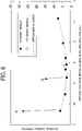
- FIG. 6 is a diagram illustrating a comparative example of an adhesion strength of a sheet P when a bias is applied on an every-other-sheet basis in the configuration illustrated in FIG. 3 .
- the diagram in FIG. 6 illustrates a relation between a constant-voltage-bias applied voltage and a tensile force.
- a hole was made on the top film of four sheets P1 through P4 that overlapped one another, and a tensile force was measured with a digital force gage, so that a film adhesion strength by static electricity was measured.
- a bias was applied between the pair of bias applying rollers 81 and 82.
- a horizontal axis in FIG. 6 indicates such a bias applied between the pair of bias applying rollers 81 and 82 as an applied voltage in units of kV.
- an adhesion strength is preferably 3 N or smaller. As illustrated in FIG. 6 , if the number of sheets that had been fed since bias application was small (5-sheet repeat), an adhesion strength was efficiently lowered where an applied voltage was in a wide range of 3 kV to 5 kV. However, experiments have revealed that if the number of fed sheets was increased (155-sheet repeat), an adhesion strength could be sufficiently lowered where an applied voltage was in one portion of the range near -4 kV, whereas an adhesion strength was immediately increased where an applied voltage reached -4.72 kV or greater. In addition, in a case where the adhesion strength was increased, a jam occurred due to sheet adhesion in a conveyance path. In FIG. 6 , a white circle with ⁇ inside indicates a case in which such a jam occurred before a 155-sheet repeat was completed.
- the constant-current power source 84 is used as a power source that applies a bias to the pair of bias applying rollers 81 and 82.
- control by a constant-current limits an electric charge amount (i.e., an electric current value) flowing from the constant-current power source 84 to a sheet P per unit time to a certain range even if, for example, electric discharge occurs. That is, even if an electrical resistance of the sheet P is decreased by accumulation of heat, the use of the constant-current power source 84 can limit an electric charge amount to flow, and thus does not cause an increase in charging.
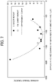
- FIG. 7 illustrates a result of experiments using an adhesion strength measurement method that is similar to the method described with reference to FIG. 6 .
- a horizontal axis in FIG. 7 indicates an electric current value ⁇ A.
- the diagram in FIG. 7 illustrates a relation between a constant-voltage-bias applied current and a tensile force.
- the use of the constant-current power source 84 to perform control with a certain electric current value could prevent electrostatic adhesion.
- the voltage herein was between -5.31 kV and -4.68 kV as illustrated in FIG. 8 .
- the diagram in FIG. 8 illustrates a relation between a constant-voltage-bias applied voltage and a tensile force.
- the image forming method is performed using the image forming device 400 which forms a toner image on a sheet P, the fixing device 6 which fixes the toner image on the sheet P, and the pair of bias applying rollers 81 and 82 which apply electric charges to the sheet P on which the toner image has been fixed by the fixing device 6, in a state in which the output-adjustable constant-current power source 84 for the bias applying rollers 81 and 82 has an electric current that is controlled to be constant.
- the sheet P subsequent to image formation is charged by the pair of bias applying rollers 81 and 82, thereby preventing adhesin of the sheet P.
- a reduction effect by which sheet adhesion due to static electricity is reduced remains, and an electrostatic sheet-jam does not occur in a conveyance path of the apparatus.
- an electric charge having a polarity opposite to a surface potential of the sheet P subsequent to fixing is applied on an every-other-sheet basis to the sheets on which images are successively formed.
- the charged sheets P has a polarity opposite to the odd-numbered sheet or even-numbered sheet, thereby further preventing adhesion of the sheet P.
- a voltage having a polarity opposite to a surface potential of the sheet P subsequent to fixing is applied to the sheet P.
- Such a method enables surfaces of sheets P facing each other are charged with static electricity so as to repel each other, thereby further preventing adhesion of the sheet P.
- the pair of bias applying rollers 81 and 82 is connected to the output-adjustable constant-current power source 84, and has a function as a charge applying device that applies an electric charge to the sheet P on which a toner image has been fixed by the fixing device 6. According to such a configuration, a sheet P is charged by the pair of bias applying rollers 81 and 82, so that adhesion of sheet P can be prevented.
- the pair of bias applying rollers 81 and 82 has a function as a reverse-polarity applying device that applies an electric charge having a polarity opposite to a surface potential of the sheet P subsequent to fixing on an every-other-sheet basis to the sheets P on which images are successively formed. According to such a configuration, even if the number of sheets is repeatedly large, a reduction effect by which sheet adhesion due to static electricity is reduced remains, and an electrostatic sheet-jam is prevented in a conveyance path of the apparatus.
- the image forming apparatus of the present disclosure has been described using an example case in which single-color developer is used.
- the present disclosure may be applied to an image forming apparatus capable of printing an image with other colors.
Landscapes
- Physics & Mathematics (AREA)
- General Physics & Mathematics (AREA)
- Engineering & Computer Science (AREA)
- Plasma & Fusion (AREA)
- Fixing For Electrophotography (AREA)
- Electrostatic Charge, Transfer And Separation In Electrography (AREA)
- Control Or Security For Electrophotography (AREA)
Applications Claiming Priority (1)
| Application Number | Priority Date | Filing Date | Title |
|---|---|---|---|
| JP2021077720A JP2022171206A (ja) | 2021-04-30 | 2021-04-30 | 画像形成方法及び画像形成装置 |
Publications (1)
| Publication Number | Publication Date |
|---|---|
| EP4083714A1 true EP4083714A1 (fr) | 2022-11-02 |
Family
ID=81346090
Family Applications (1)
| Application Number | Title | Priority Date | Filing Date |
|---|---|---|---|
| EP22169429.2A Pending EP4083714A1 (fr) | 2021-04-30 | 2022-04-22 | Procédé et appareil de formation d'image |
Country Status (4)
| Country | Link |
|---|---|
| US (1) | US11681238B2 (fr) |
| EP (1) | EP4083714A1 (fr) |
| JP (1) | JP2022171206A (fr) |
| CN (1) | CN115268238A (fr) |
Families Citing this family (4)
| Publication number | Priority date | Publication date | Assignee | Title |
|---|---|---|---|---|
| EP4411484A1 (fr) | 2023-01-30 | 2024-08-07 | Canon Kabushiki Kaisha | Appareil d'élimination de charge, appareil de formation d'image et appareil de réglage de charge |
| US12360485B2 (en) | 2023-02-22 | 2025-07-15 | Canon Kabushiki Kaisha | Image forming system and charge eliminating apparatus |
| US12468252B2 (en) | 2023-04-24 | 2025-11-11 | Canon Kabushiki Kaisha | Charge eliminating apparatus, image forming system, and charge adjusting apparatus |
| JP2026054345A (ja) | 2024-09-13 | 2026-03-26 | キヤノン株式会社 | 除電装置及び画像形成システム、電荷調整装置 |
Citations (9)
| Publication number | Priority date | Publication date | Assignee | Title |
|---|---|---|---|---|
| JPS5915865B2 (ja) | 1975-10-13 | 1984-04-12 | 株式会社リコー | シ−ト給送装置におけるスキュ−矯正方法 |
| JPH0150187B2 (fr) | 1983-02-08 | 1989-10-27 | Sanken Electric Co Ltd | |
| JPH0240210B2 (ja) | 1984-11-07 | 1990-09-10 | Marukon Denshi Kk | Denkaikondensanoseizohoho |
| JP2015067433A (ja) | 2013-09-30 | 2015-04-13 | コニカミノルタ株式会社 | 画像形成装置、画像形成システムおよび画像形成方法 |
| JP2016122154A (ja) | 2014-12-25 | 2016-07-07 | コニカミノルタ株式会社 | 画像形成システム、画像形成装置、および後処理装置 |
| JP2016122155A (ja) * | 2014-12-25 | 2016-07-07 | コニカミノルタ株式会社 | 画像形成システム、画像形成方法、および電荷調整装置 |
| EP3048488A1 (fr) * | 2014-12-25 | 2016-07-27 | Konica Minolta, Inc. | Système et procédé de formation d'image et dispositif de réglage de charge |
| JP2016210575A (ja) | 2015-05-11 | 2016-12-15 | コニカミノルタ株式会社 | 画像形成システム、画像形成方法、および電荷調整装置 |
| US20170139367A1 (en) * | 2015-11-18 | 2017-05-18 | Konica Minolta, Inc. | Image forming system and conveying control method |
Family Cites Families (9)
| Publication number | Priority date | Publication date | Assignee | Title |
|---|---|---|---|---|
| JP5585870B2 (ja) * | 2010-08-20 | 2014-09-10 | 株式会社リコー | 画像形成装置 |
| US9152090B2 (en) * | 2012-07-20 | 2015-10-06 | Ricoh Company, Limited | Image forming apparatus that suppresses deterioration in image quality |
| JP2014102495A (ja) | 2012-10-23 | 2014-06-05 | Ricoh Co Ltd | 現像装置および画像形成装置 |
| EP2947516A1 (fr) | 2014-05-22 | 2015-11-25 | Ricoh Company, Ltd. | Dispositif de développement, appareil de formation d'images et cartouche de traitement les intégrant |
| US9625851B2 (en) | 2015-02-13 | 2017-04-18 | Ricoh Company, Ltd. | Developing device and image forming apparatus incorporating same |
| JP6729172B2 (ja) * | 2016-08-24 | 2020-07-22 | コニカミノルタ株式会社 | 画像形成装置および画像形成方法 |
| JP2021076723A (ja) | 2019-11-08 | 2021-05-20 | 株式会社リコー | 画像形成装置、用紙処理方法及び用紙処理プログラム |
| JP7478343B2 (ja) | 2020-04-07 | 2024-05-07 | 株式会社リコー | 画像形成方法および画像形成装置 |
| JP7625810B2 (ja) | 2020-09-10 | 2025-02-04 | 株式会社リコー | 再剥離性情報シートの作製方法 |
-
2021
- 2021-04-30 JP JP2021077720A patent/JP2022171206A/ja active Pending
-
2022
- 2022-04-18 US US17/722,402 patent/US11681238B2/en active Active
- 2022-04-19 CN CN202210409610.1A patent/CN115268238A/zh active Pending
- 2022-04-22 EP EP22169429.2A patent/EP4083714A1/fr active Pending
Patent Citations (9)
| Publication number | Priority date | Publication date | Assignee | Title |
|---|---|---|---|---|
| JPS5915865B2 (ja) | 1975-10-13 | 1984-04-12 | 株式会社リコー | シ−ト給送装置におけるスキュ−矯正方法 |
| JPH0150187B2 (fr) | 1983-02-08 | 1989-10-27 | Sanken Electric Co Ltd | |
| JPH0240210B2 (ja) | 1984-11-07 | 1990-09-10 | Marukon Denshi Kk | Denkaikondensanoseizohoho |
| JP2015067433A (ja) | 2013-09-30 | 2015-04-13 | コニカミノルタ株式会社 | 画像形成装置、画像形成システムおよび画像形成方法 |
| JP2016122154A (ja) | 2014-12-25 | 2016-07-07 | コニカミノルタ株式会社 | 画像形成システム、画像形成装置、および後処理装置 |
| JP2016122155A (ja) * | 2014-12-25 | 2016-07-07 | コニカミノルタ株式会社 | 画像形成システム、画像形成方法、および電荷調整装置 |
| EP3048488A1 (fr) * | 2014-12-25 | 2016-07-27 | Konica Minolta, Inc. | Système et procédé de formation d'image et dispositif de réglage de charge |
| JP2016210575A (ja) | 2015-05-11 | 2016-12-15 | コニカミノルタ株式会社 | 画像形成システム、画像形成方法、および電荷調整装置 |
| US20170139367A1 (en) * | 2015-11-18 | 2017-05-18 | Konica Minolta, Inc. | Image forming system and conveying control method |
Also Published As
| Publication number | Publication date |
|---|---|
| JP2022171206A (ja) | 2022-11-11 |
| US20220350271A1 (en) | 2022-11-03 |
| US11681238B2 (en) | 2023-06-20 |
| CN115268238A (zh) | 2022-11-01 |
Similar Documents
| Publication | Publication Date | Title |
|---|---|---|
| EP4083714A1 (fr) | Procédé et appareil de formation d'image | |
| US8532547B2 (en) | Transfer belt unit and image forming apparatus | |
| US9720364B2 (en) | Image forming apparatus | |
| CN102998947A (zh) | 图像形成装置 | |
| US7848671B2 (en) | Image forming apparatus with multiple image forming portions and image transfers | |
| US20160195837A1 (en) | Image forming apparatus | |
| US10372071B2 (en) | Image forming apparatus | |
| US7720401B2 (en) | Inter-document zone gloss defect eliminator | |
| JP2004272206A (ja) | 画像形成装置 | |
| US9541865B2 (en) | Image forming apparatus with a controller to control an alternating transfer bias | |
| JP3600102B2 (ja) | カラー画像形成装置 | |
| US20180246451A1 (en) | Image forming apparatus | |
| JP2001272833A (ja) | 画像形成装置 | |
| US12393135B2 (en) | Image forming apparatus | |
| US9417547B2 (en) | Image forming apparatus | |
| JP4974102B2 (ja) | 画像形成装置 | |
| US12360485B2 (en) | Image forming system and charge eliminating apparatus | |
| US9383690B1 (en) | Transfer device and image forming apparatus | |
| JP2014038148A (ja) | 画像形成装置 | |
| US9031467B2 (en) | Discharge device | |
| US20260010104A1 (en) | Image forming apparatus including charge removing apparatus and image forming apparatus including charge application apparatus | |
| US8478173B2 (en) | Limited ozone generator transfer device | |
| US10719039B2 (en) | Image forming apparatus including a second power supply that applies a voltage with a same polarity as a toner to a discharging member to charge toner on a secondary transfer roller | |
| EP3835873A1 (fr) | Appareil de formation d'images et méthode de contrôle du transport du support | |
| JP2018151593A (ja) | 画像形成装置、除電部材の寿命検出方法及び画像形成装置の管理システム |
Legal Events
| Date | Code | Title | Description |
|---|---|---|---|
| PUAI | Public reference made under article 153(3) epc to a published international application that has entered the european phase |
Free format text: ORIGINAL CODE: 0009012 |
|
| STAA | Information on the status of an ep patent application or granted ep patent |
Free format text: STATUS: REQUEST FOR EXAMINATION WAS MADE |
|
| 17P | Request for examination filed |
Effective date: 20220422 |
|
| AK | Designated contracting states |
Kind code of ref document: A1 Designated state(s): AL AT BE BG CH CY CZ DE DK EE ES FI FR GB GR HR HU IE IS IT LI LT LU LV MC MK MT NL NO PL PT RO RS SE SI SK SM TR |
|
| STAA | Information on the status of an ep patent application or granted ep patent |
Free format text: STATUS: EXAMINATION IS IN PROGRESS |
|
| 17Q | First examination report despatched |
Effective date: 20240923 |
|
| GRAP | Despatch of communication of intention to grant a patent |
Free format text: ORIGINAL CODE: EPIDOSNIGR1 |
|
| STAA | Information on the status of an ep patent application or granted ep patent |
Free format text: STATUS: GRANT OF PATENT IS INTENDED |