EP4083743B1 - Verfahren zur steuerung der ausrichtung eines suntrackers, das auf kartografischen modellen basiert - Google Patents
Verfahren zur steuerung der ausrichtung eines suntrackers, das auf kartografischen modellen basiert Download PDFInfo
- Publication number
- EP4083743B1 EP4083743B1 EP22181268.8A EP22181268A EP4083743B1 EP 4083743 B1 EP4083743 B1 EP 4083743B1 EP 22181268 A EP22181268 A EP 22181268A EP 4083743 B1 EP4083743 B1 EP 4083743B1
- Authority
- EP
- European Patent Office
- Prior art keywords
- solar
- cloud coverage
- orientation
- model
- value
- Prior art date
- Legal status (The legal status is an assumption and is not a legal conclusion. Google has not performed a legal analysis and makes no representation as to the accuracy of the status listed.)
- Active
Links
Images



Classifications
-
- G—PHYSICS
- G05—CONTROLLING; REGULATING
- G05D—SYSTEMS FOR CONTROLLING OR REGULATING NON-ELECTRIC VARIABLES
- G05D3/00—Control of position or direction
- G05D3/10—Control of position or direction without using feedback
-
- G—PHYSICS
- G01—MEASURING; TESTING
- G01S—RADIO DIRECTION-FINDING; RADIO NAVIGATION; DETERMINING DISTANCE OR VELOCITY BY USE OF RADIO WAVES; LOCATING OR PRESENCE-DETECTING BY USE OF THE REFLECTION OR RERADIATION OF RADIO WAVES; ANALOGOUS ARRANGEMENTS USING OTHER WAVES
- G01S3/00—Direction-finders for determining the direction from which infrasonic, sonic, ultrasonic or electromagnetic waves, or particle emission, not having a directional significance, are being received
- G01S3/78—Direction-finders for determining the direction from which infrasonic, sonic, ultrasonic or electromagnetic waves, or particle emission, not having a directional significance, are being received using electromagnetic waves other than radio waves
- G01S3/782—Systems for determining direction or deviation from predetermined direction
- G01S3/785—Systems for determining direction or deviation from predetermined direction using adjustment of orientation of directivity characteristics of a detector or detector system to give a desired condition of signal derived from that detector or detector system
- G01S3/786—Systems for determining direction or deviation from predetermined direction using adjustment of orientation of directivity characteristics of a detector or detector system to give a desired condition of signal derived from that detector or detector system the desired condition being maintained automatically
- G01S3/7861—Solar tracking systems
-
- F—MECHANICAL ENGINEERING; LIGHTING; HEATING; WEAPONS; BLASTING
- F24—HEATING; RANGES; VENTILATING
- F24S—SOLAR HEAT COLLECTORS; SOLAR HEAT SYSTEMS
- F24S50/00—Arrangements for controlling solar heat collectors
- F24S50/20—Arrangements for controlling solar heat collectors for tracking
-
- G—PHYSICS
- G05—CONTROLLING; REGULATING
- G05D—SYSTEMS FOR CONTROLLING OR REGULATING NON-ELECTRIC VARIABLES
- G05D3/00—Control of position or direction
- G05D3/10—Control of position or direction without using feedback
- G05D3/105—Solar tracker
-
- H—ELECTRICITY
- H02—GENERATION; CONVERSION OR DISTRIBUTION OF ELECTRIC POWER
- H02S—GENERATION OF ELECTRIC POWER BY CONVERSION OF INFRARED RADIATION, VISIBLE LIGHT OR ULTRAVIOLET LIGHT, e.g. USING PHOTOVOLTAIC [PV] MODULES
- H02S20/00—Supporting structures for PV modules
- H02S20/10—Supporting structures directly fixed to the ground
-
- H—ELECTRICITY
- H02—GENERATION; CONVERSION OR DISTRIBUTION OF ELECTRIC POWER
- H02S—GENERATION OF ELECTRIC POWER BY CONVERSION OF INFRARED RADIATION, VISIBLE LIGHT OR ULTRAVIOLET LIGHT, e.g. USING PHOTOVOLTAIC [PV] MODULES
- H02S20/00—Supporting structures for PV modules
- H02S20/30—Supporting structures being movable or adjustable, e.g. for angle adjustment
- H02S20/32—Supporting structures being movable or adjustable, e.g. for angle adjustment specially adapted for solar tracking
-
- H—ELECTRICITY
- H02—GENERATION; CONVERSION OR DISTRIBUTION OF ELECTRIC POWER
- H02S—GENERATION OF ELECTRIC POWER BY CONVERSION OF INFRARED RADIATION, VISIBLE LIGHT OR ULTRAVIOLET LIGHT, e.g. USING PHOTOVOLTAIC [PV] MODULES
- H02S40/00—Components or accessories in combination with PV modules, not provided for in groups H02S10/00 - H02S30/00
- H02S40/20—Optical components
-
- H—ELECTRICITY
- H02—GENERATION; CONVERSION OR DISTRIBUTION OF ELECTRIC POWER
- H02S—GENERATION OF ELECTRIC POWER BY CONVERSION OF INFRARED RADIATION, VISIBLE LIGHT OR ULTRAVIOLET LIGHT, e.g. USING PHOTOVOLTAIC [PV] MODULES
- H02S50/00—Monitoring or testing of PV systems, e.g. load balancing or fault identification
-
- F—MECHANICAL ENGINEERING; LIGHTING; HEATING; WEAPONS; BLASTING
- F24—HEATING; RANGES; VENTILATING
- F24S—SOLAR HEAT COLLECTORS; SOLAR HEAT SYSTEMS
- F24S2201/00—Prediction; Simulation
-
- Y—GENERAL TAGGING OF NEW TECHNOLOGICAL DEVELOPMENTS; GENERAL TAGGING OF CROSS-SECTIONAL TECHNOLOGIES SPANNING OVER SEVERAL SECTIONS OF THE IPC; TECHNICAL SUBJECTS COVERED BY FORMER USPC CROSS-REFERENCE ART COLLECTIONS [XRACs] AND DIGESTS
- Y02—TECHNOLOGIES OR APPLICATIONS FOR MITIGATION OR ADAPTATION AGAINST CLIMATE CHANGE
- Y02E—REDUCTION OF GREENHOUSE GAS [GHG] EMISSIONS, RELATED TO ENERGY GENERATION, TRANSMISSION OR DISTRIBUTION
- Y02E10/00—Energy generation through renewable energy sources
- Y02E10/40—Solar thermal energy, e.g. solar towers
- Y02E10/47—Mountings or tracking
Definitions
- the present invention relates to a method for controlling the orientation of a single-axis solar tracker, as well as to a single-axis solar tracker designed for implementing such a method.
- the invention relates to the field of solar trackers, otherwise called tracking support systems or "solar trackers", intended to support solar sensors, generally of the photovoltaic panel type.
- solar trackers of the single-axis type i.e. orientable along a single main axis of rotation, for a rotation allowing the sun to be followed during its rise and fall from east to west.
- a main axis of rotation generally extends horizontally and substantially parallel to the ground on which the solar tracker is anchored.
- US 2007/084502 A1 discloses a method for controlling the orientation of a solar tracker, orientable around an axis of rotation, said method repeatedly performing successive control phases, where each control phase implements the following successive steps: observing the cloud cover above the solar tracker, comparing the observed cloud cover with cloud cover models, each cloud cover model being associated with an orientation instruction for the solar tracker, comparing the observed cloud cover with a cloud cover model and controlling the orientation of the solar tracker by applying the orientation instruction associated with said cloud cover model retained during the step.
- U1 discloses sensors and electronics for open space tracking control with photovoltaic modules.
- US 2013/256506 A1 discloses a laterally adjustable automatic solar tracking device.
- FIG. 1 This type of control, however, has a major drawback in that it offers a deficit in performance in certain weather conditions, and we will usefully refer to the figure 1 for explanation; this figure 1 comprising four diagrams (1 a), (1 b), (1 c) and (1 d) each illustrating two ST solar trackers in different weather conditions, with the sun SO always at the same position and with the ST solar trackers always oriented facing the sun.
- Diagram (1 a) illustrates ideal weather conditions, in the absence of clouds, and the solar trackers ST are oriented facing the sun SO in order to benefit from maximum direct solar radiation Rdir.
- the servocontrol on the position of the sun SO provides maximum operation; such a servocontrol corresponding to a servocontrol of the orientation of the solar tracker on a so-called direct tilt angle defined by the direction of direct solar radiation Rdir at the level of the solar tracker.
- Figures (1b), (1c) and (1d) illustrate degraded weather conditions, with different cloud cover. depending in particular on the cloud surface or covered surface, the types of NU clouds present, the number and position of NU clouds relative to the sun SO.
- the servoing on the position of the sun SO may not provide the best performance, by not taking into account the diffuse solar radiation Rdif.
- the diffuse solar radiation Rdif occurs when the direct solar radiation Rdir is scattered in the clouds NU and atmospheric particles.
- the diffuse solar radiation Rdif results from the diffraction of light by the clouds NU and the various molecules suspended in the atmosphere. The diffuse solar radiation Rdif therefore does not necessarily follow the direction defined by the sun SO towards the observation point on the surface of the Earth.
- the ST solar trackers are all oriented at the direct tilt angle (facing the sun) while orientations at diffuse tilt angles would provide better efficiencies.
- the person skilled in the art would be tempted to control, in real time, the orientation of the solar tracker to an optimal tilt angle corresponding to maximum solar radiation.
- the optimal tilt angle would correspond to the direct tilt angle and, in the presence of cloud cover or even a single cloud in front of the sun, the optimal tilt angle would correspond to a diffuse tilt angle. To do this, it would suffice to measure the amplitude of the radiation in different directions (or different inclinations), and to establish the direction corresponding to a maximum amplitude to deduce the optimal tilt angle.
- the solar tracker may be required to change orientation more or less often and more or less quickly.
- each change of orientation requires at least one actuator (generally an electric motor), generating electrical consumption and wear on the mechanical components required by the change of orientation (motor components, bearings, rotating guide elements, etc.). This electrical consumption and wear will not necessarily be offset by the productivity gains obtained by adjusting to the optimal tilt angle in real time.
- the optimal tilt angle corresponds to the direct tilt angle (due to the absence of clouds between the sun and the solar tracker)
- the optimal tilt angle will be modified during these few minutes and then recover the direct tilt angle. Controlling the orientation of the solar tracker in real time to the optimal tilt angle would, in this case, lead to moving the solar tracker during these few minutes, for a benefit that is certainly very low in relation to the electrical consumption of the actuator(s) and the wear.
- the present invention aims to resolve these drawbacks by proposing a method for controlling the orientation of a single-axis solar tracker, implementing a step of comparing real observations of cloud cover with cloud cover models archived in a database, so as not to systematically control the orientation of the solar tracker on the optimal tilt angle, but to apply an advantageous compromise between the gains in solar energy productivity and the losses in electrical consumption of the actuator(s), and possibly taking into account the wear caused by the changes in orientation.
- the method implements a comparison between observations of the cloud layer and predefined theoretical models and to which are associated orientation instructions established to avoid requesting the solar tracker too often in orientation changes which would provide little energy gain, or even provide energy losses, as would be the case for example if a single cloud passes in front of the sun for a short time.
- the control and servo-control of the orientation of the solar tracker relates to the control and servo-control of its inclination around its axis of rotation, and in particular its angle of inclination around this axis.
- each cloud cover model associates an orientation instruction which is a function of a composition of the cloud layer of said model, said composition depending on at least one of the following parameters: number of clouds, covering surface of the cloud(s), thickness of the cloud(s), location of the cloud(s); type of the cloud(s).
- each cloud cover model is built to match as many real-world situations as possible.
- the corresponding orientation instruction is predefined according to at least one of the following parameters: a wear rate of mechanical parts of the solar tracker used during a change in orientation of the solar tracker, an energy consumption required to change the orientation of the solar tracker and a speed of movement of the solar tracker when changing orientation.
- a servocontrol on the direct tilt angle (facing the sun) is provided, while in the large cloud cover model, a servocontrol on another tilt angle called optimized to take into account diffuse radiation is provided.
- the optimized tilt angle corresponds to an angle associated with a horizontal setting of the solar tracker.
- the cloud cover models comprise at least one so-called thin cloud cover model with which an orientation instruction is associated at a predefined intermediate angle between the direct tilt angle and an angle corresponding to a horizontal setting of the solar tracker.
- the cloud cover models comprise at least one so-called irregular cloud cover model with which an orientation instruction on the direct tilt angle is associated.
- a control is provided on the direct tilt angle (facing the sun), so as not to modify the orientation of the tracker each time a cloud passes in front of the sun.
- step a) the observation of the cloud cover is translated into a mapping of the solar luminance as a function of different elevation angles and, in step b), the cloud cover models are made up of cartographic models and the comparison is based on a comparison between the distribution of the solar luminance on the mapping with the distribution of the solar luminance in the different cartographic models.
- step b) the distribution in the observation space of the solar luminance values of the map is compared with that of the different theoretical models; this observation space being either two-dimensional if the map is established along two axes, preferably the north-south axis and the east-west axis, or one-dimensional if the map is established along one axis, in this case the east-west axis.
- the reconciliation made during step c) is also based on a reconciliation of the distribution of solar luminance on the map with a cartographic model presenting a close or similar distribution with a predefined deviation tolerance.
- the sun's elevation angle is the angle around the sun tracker's rotation axis, between the horizontal plane and the plane passing through the sun tracker's rotation axis and parallel to the sun's rays.
- the thin cloud cover model corresponds to a cartographic model where the solar luminance has, over an angular sector greater than 150 degrees, a low value and a high value, with a difference between the low value and the high value which is less than 50% of the high value and with the high value which is associated with an elevation angle located less than 20 degrees from the direct inclination angle.
- the irregular cloud cover model corresponds to a cartographic model where the solar luminance is at least equal to 50% of the maximum value over an angular sector less than 30 degrees around the direct tilt angle, and is at least equal to 20% of the maximum value over an angular sector less than 30 degrees around another tilt angle.
- the observation corresponds to an image.
- the observation corresponds to a matrix of measurements made individually by each photosensitive cell, these photosensitive cells being positioned at different elevation angles.
- the observation corresponds to a satellite image of the area concerned.
- a frequency weighting step is implemented applied to the observation which is a function of both a frequency response of the observation and a frequency band useful to the solar sensor.
- the frequency weighting will consist of applying a frequency filter which will take into account the spectral response of the solar sensor.
- the method switches to a control on said second orientation instruction only if the first series is followed by a second series comprising a predefined number of successive piloting phases all retaining the second cloud cover model during their respective steps c).
- the second orientation instruction will be taken into account only if the observation is close to the second cloud cover model for a minimum of time.
- the method maintains the control on said first orientation instruction or switches to control on a direct tilt angle.
- the predefined number of successive control phases of the second series is a function of at least one of the following parameters: the schedule, the angular difference between the first orientation setpoint and the second orientation setpoint, a wear rate of mechanical components of the solar tracker used during a change of orientation of the solar tracker, and an energy consumption necessary to modify the orientation of the solar tracker.
- the process switches to a control on a direct tilt angle if during a series comprising a predefined number of successive piloting phases where, during each piloting phase, no cloud cover model from the database is brought closer to the cloud cover observed cloudiness.
- the invention also relates to a single-axis solar tracker orientable around an axis of rotation, of the type comprising a fixed structure for anchoring to the ground and a platform capable of supporting at least one solar collector, said platform being operable in rotation on the fixed structure along said axis of rotation by means of an actuation system, said solar tracker being remarkable in that it further comprises a system for observing the evolution over time of the cloud cover above the solar tracker and a control unit connected, on the one hand, to the observation system for receiving its observation data and, on the other hand, to the actuation system for controlling the rotation of the platform, where said control unit is configured to implement steps b) to e) of the control method as described above.
- a single-axis solar tracker 1 orientable around an axis of rotation A, of the type comprising a fixed structure 11 for anchoring to the ground consisting of one or more pylons anchored to the ground, by for example by beating, screwing, bolting, ballast, or other equivalent means allowing the fixed structure 11 to be fixed and stabilized on the ground.
- the solar tracker 1 further comprises a mobile platform 12 rotatably mounted on the fixed structure 11 along the axis of rotation A, and more specifically rotatably mounted on the upper ends of the pylons.
- This platform 12 is capable of supporting at least one solar collector 13, and in particular one or more photovoltaic panels.
- the rotation axis A is substantially horizontal and directed along a longitudinal axis X in the north-south direction.
- the platform 12 extends along a horizontal plane defined by the longitudinal axis X and by a transverse axis Y in the east-west direction, orthogonally to a vertical axis Z.
- the angle of inclination of the solar tracker 1 corresponds to the angle of the normal to the platform 12 with respect to the vertical axis Z taken in the plane (Y, Z).
- this tilt angle is 0 degrees.
- the solar tracker 1 also comprises an observation system 2 of the cloud cover above the solar tracker 1, in other words for observing the sky above the solar tracker 1.
- This observation system 2 can be associated with a single solar tracker 1 or, economically, be shared with several solar trackers.
- the observation system 2 is fixed, and can be raised above the ground by being mounted, for example, on a pole 20.
- the solar tracker 1 further comprises an actuation system (not shown in the figure 2 and bearing the numerical reference 3 on the figure 13 ) which ensures the rotation of the platform 12 along the axis of rotation A.
- This actuation system 3 comprises an actuator, for example of the cylinder type (electric, pneumatic or hydraulic) or electric motor (for example rotary motor).
- This actuation system 3 further comprises a mechanical system for transmitting the movement at the output of the actuator (rotary movement for a rotary motor, or linear movement for a cylinder) into a rotational movement of the platform 12.
- This mechanical transmission system may be, by way of non-limiting example, a deformable parallelogram system, a pulley return system, a pinion system, a chain system, a belt system, a dog system, a system with transmission shaft, a connecting rod system, etc.
- the actuator is specific to the solar tracker 1, or is shared between several solar trackers.
- the platforms 12 of the different solar trackers are advantageously coupled in rotation, for a synchronous rotation under the effect of the common actuator.
- the solar tracker 1 also comprises a control unit 4 of the electronic card type, which is connected to the observation system 2 in order to receive its observations (or observation data) and which is also connected to the actuation system 3 to control its operation and thus control the rotation of the platform 12, in other words the orientation of the solar tracker 1.
- this control unit 4 can be specific to the solar tracker 1, or be shared between several solar trackers, and preferably between several solar trackers grouped in a line (extending from north to south) within linear solar installations.
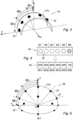
- the observation system 2a comprises a support 21a in the form of a semi-circular arch centered around an axis X parallel to the axis of rotation A of the solar tracker, this support 21a supporting photosensitive cells 22.
- These photosensitive cells 22 are positioned along several bands (visible on the figures 4 And 7b ) distributed according to several so-called elevation angles Oi which are measured with respect to the vertical axis Z in the plane (Y, Z) around the axis X, the reference (X, Y, Z) being centered on the center O of the arched support 21a.
- the elevation angle Oi is therefore to be compared with the angle of inclination of the solar tracker 1.
- These elevation angles Oi and these bands Bi are also visible on the Figure 7b .
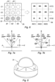
- the observation system 2b comprises a hemispherical dome-shaped support 21b supporting photosensitive cells 22.
- These photosensitive cells 22 are positioned along several Bi bands (visible on the Figure 6 and 7b ) distributed according to several so-called elevation angles Oi which are measured with respect to the vertical axis Z in the plane (Y, Z) around the axis X, the reference (X, Y, Z) being centered on the center O of the hemispherical dome 21.
- the elevation angle Oi is therefore to be compared with the angle of inclination of the solar tracker 1.
- each strip Bi there are present one or more photosensitive cells 22.
- the photosensitive cells 22 of the same band Bi are distributed according to several so-called azimuth angles Rj which are measured with respect to the vertical axis Z in the plane (X, Z) around the axis Y.
- the photosensitive cells 22 are also distributed according to columns Cj (visible on the Figures 6 and 7a ) at different azimuth angles Rj; these azimuth angles Rj are visible on the Figure 7a .
- These photosensitive cells 22 can be of the same technology as the photovoltaic panels 13 in order to be able to apply a weighting depending on the wavelength range useful to the photovoltaic panels 13. Preferably, these photosensitive cells 22 will be subject to prior calibration to obtain better precision.
- the cartographic module 40 converts an observation made by the first or second observation system 2a, 2b into a mapping 5a, 5b of the solar luminance which is one-dimensional for the first observation system 2a (see the mapping 5a visible on the figure 4 ) or two-dimensional for the second observation system 2b (see mapping 5b visible on the figure 6 ).
- the one-dimensional mapping 5a forms a solar luminance map comprising several bands 50(i) (i integer) distributed or established in a direction parallel to the transverse axis Y (in other words in an east-west direction), and associated respectively with different elevation or inclination angles Oi, such that each band 50(i) corresponds to an inclination angle Oi of the solar tracker 1; this elevation angle Oi being, as a reminder, measured around the north-south axis X.
- the one-dimensional 5a map includes NB bands 50(i) (where NB corresponds to the number of photosensitive cells 22) and each band 50(i) corresponds to a value (absolute or relative) of solar luminance Lum(i).
- first observation system 2a On the figure 4 at the top, an example of a first observation system 2a is schematically illustrated flat and comprises six photosensitive cells 22 distributed according to six bands B1 to B6 which are associated with six elevation angles (or inclination angles).
- This first observation system 2a corresponds to a one-dimensional mapping 5a with six bands 50(1) to 50(6), and where the solar luminance values are expressed in a relative manner as a percentage with respect to a maximum solar luminance value corresponding to the maximum value of the solar luminance accessible during an observation in direct radiation. Thus, a percentage of 100% corresponds to this maximum solar luminance value.
- the two-dimensional 5b map includes NT boxes (where NT corresponds to the number of photosensitive cells 22) and each box corresponds to a value (absolute or relative) of solar luminance Lum(i, j).
- FIG. 6 on the left an example of a second observation system 2b is schematically illustrated flat and comprises nine photosensitive cells 22 distributed according to three bands B1, B2, B3 which are associated with three elevation angles (or inclination angles), and according to three columns C1, C2, C3 which are associated with three azimuth angles.
- To this second observation system 2b corresponds a two-dimensional mapping 5b with three bands 50(1), 50(2), 50(3) and three columns 51(1), 51(2), 51(3), and where the Solar luminance values are expressed relatively as a percentage of a maximum solar luminance value.
- the 2c observation system comprises a camera, in particular of the hemispherical camera type, in order to extract images of the sky.
- the third observation system 2c (hereinafter called the camera) is configured to take images in a spectral width sufficient for the technology of the solar sensors 13, and in particular of the photovoltaic panel(s).
- the camera 2c delivers a raw IMB image of the sky which is then delivered to the cartographic module 40 to convert this raw IMB image (or observation) into a two-dimensional 5 map of the solar luminance.
- This two-dimensional raw IMB image is associated with a reference (X, Y), these X and Y axes having already been defined above.
- the mapping module 40 implements a succession of image processing steps to start from the raw image IMB up to the 5c mapping.
- the mapping module 40 implements a frequency weighting applied to the recovered raw image IMB (or video signal), to obtain a so-called weighted image IMP; this frequency weighting consists of applying a frequency filter to the observation (such a weighting can also be applied to the observation made by the first and second observation systems 2a, 2b) which is a function of both the frequency response of the observation system 2 (whether the photosensitive cells 22 or the camera 2c) and the useful frequency band (or spectral response) to the photovoltaic panels 13.
- the cartographic module 40 implements a processing of the weighted image IMP consisting in correcting the image of defects (noise suppression processing, glare or "blooming" processing, saturation processing, etc.) to obtain a so-called IMT processed image.
- a processing of the weighted image IMP consisting in correcting the image of defects (noise suppression processing, glare or "blooming" processing, saturation processing, etc.) to obtain a so-called IMT processed image.
- the cartographic module 40 implements a calculation (either pixel by pixel, or zone by zone where each zone comprises several pixels) of the distribution of the solar luminance on the IMT processed image in order to generate an initial two-dimensional CI mapping forming a map (or matrix) of solar luminance distributed according to several bands associated respectively with different elevation or inclination angles ⁇ (i) and according to several columns associated respectively with different azimuth angles; on the figure 9 , the solar luminance values of the initial CI mapping are expressed relatively as a percentage of the maximum solar luminance value.
- the mapping module 40 applies to the initial mapping CI a coefficient dependent on the variation of the sensitivity of the camera 2, in order to generate a two-dimensional mapping 5c of the same type as the two-dimensional mapping 5b described above.
- the amplitude (or brightness) of the data delivered by the camera 2 is proportionally linked to the value of the solar radiation, so that this coefficient takes into account this proportionality dependent on the variation of the sensitivity of the camera 2.
- the cartographic module 40 generates a two-dimensional 5c map forming a map (or matrix) of solar luminance distributed according to several bands 50(i) associated respectively with different elevation or inclination angles Oi and according to several columns 51(j) associated respectively with different azimuth angles Rj.
- the map 5 comprises five bands 50(1), ..., 50(5) and seven columns 51(1), ..., 51(7), and the solar luminance values are expressed relatively as a percentage of the maximum solar luminance value.
- the resolution of the mapping 5 (in other words the number of bands and columns) and therefore the angular precision depend on the fineness of the image processing implemented by the mapping module 40, and also on the sensitivity and resolution of the observation system 2.
- this sensitivity depends on the sensitivity of the photosensitive cells 22, and this resolution depends on the number and distribution of the photosensitive cells 22.
- this sensitivity and this resolution depend on the quality of the camera.
- the comparison module 41 implements a comparison of this mapping 5a, 5b, 5c with the cartographic models 6 to extract an approaching or equivalent cartographic model 6 according to predefined matching criteria.
- the cartographies 5a being one-dimensional
- the associated cartographic models 6a are also one-dimensional, and each translate a theoretical model of cloud cover translated by a distribution of solar luminance according to several bands associated respectively with different angles of elevation or inclination Oi.
- first observation system 2a comprising 5 photosensitive cells 22 distributed at five elevation angles ⁇ 1, ⁇ 2, ⁇ 3, ⁇ 4 and ⁇
- cartographic models 6a being schematized in the form of histograms (equivalent to the cartography 5a of the figure 4 ), with on the ordinate the value of the solar luminance expressed in a relative manner as a percentage compared to the maximum value of solar luminance, and with on the abscissa the bands 50(i) (or even the elevation angles Oi).
- a first model 6a schematized by histogram 11(a) corresponds to a model of zero cloud cover, where the solar luminance is at least equal to 80% of the maximum value over an angular sector less than 30 degrees around the direct inclination angle.
- This zero cloud cover model models a sky with almost no clouds, where the direct radiation is located roughly at the elevation angle ⁇ 4.
- a second model 6a schematized by the histogram 11(b) corresponds to an irregular cloud cover model, where the solar luminance is at least equal to 50% of the maximum value over an angular sector less than 30 degrees around the direct tilt angle, and is at least equal to 20% of the maximum value over an angular sector less than 30 degrees around another tilt angle.
- This irregular cloud cover model models a sky with a single cloud or few irregularly distributed clouds, where the direct radiation is located substantially at elevation angle ⁇ 4 and the diffuse radiation from the cloud(s) is located substantially at elevation angle ⁇ 2.
- a third and fourth model 6a schematized by the histograms 11(c) and 11(d) each correspond to a model of large cloud cover, where the solar luminance presents, over an angular sector greater than 150 degrees, a low value and a high value, with a difference between the low value and the high value which is less than 50% of the high value, with the high value which is less than 50% of the maximum value and with the high value which is associated with an elevation angle at least 20 degrees away from the direct inclination angle.
- histogram 11(c) it is noted that the high value is 45% at elevation angle ⁇ 3 and the low value is 30% at elevation angles ⁇ 1 and ⁇ 5, while the direct tilt angle roughly corresponds to elevation angle ⁇ 4.
- histogram 11(d) it is noted that the high value is 20% at elevation angle ⁇ 3 and the low value is 10% at elevation angles ⁇ 1 and ⁇ 5, while the direct tilt angle roughly corresponds to elevation angle ⁇ 4.
- This large cloud cover model models an overcast sky, with a nearly uniform cloud surface over the entire observed part of the sky.
- the model in histogram 11(d) models a thicker cloud cover than in the model in histogram 11(c).
- a fifth model 6a schematized by histogram 11(e) corresponds to a model of thin cloud cover where the solar luminance presents, over an angular sector greater than 150 degrees, a low value and a high value, with a difference between the low value and the high value which is less than 50% of the high value and with the high value which is associated with an elevation angle located less than 20 degrees from the direct inclination angle.
- histogram 11(e) it is noted that the high value is 37% at the elevation angle ⁇ 4 which corresponds approximately to the angle direct tilt, and the low value is 20% at the elevation angle ⁇ 1 furthest from the elevation angle ⁇ 4.
- the associated cartographic models 6 are also two-dimensional, and each translate a theoretical model of cloud cover translated by a distribution of solar luminance according to several bands associated respectively with different elevation or inclination angles Oi and according to several columns associated respectively with different azimuth angles Rj.
- the cartographic module 40 will have to convert the two-dimensional 5b, 5c cartographies into an equivalent one-dimensional cartography.
- this conversion consists in calculating, for each band 50(i) of the two-dimensional 5c mapping, an equivalent luminance value Leq(i) from all the luminance values L(i, j) taken in the band 50(i).
- a first model 6c schematized by image 12(a) corresponds to a model of zero cloud cover, just like model 6a of histogram 11(a), where the SW sun is fully visible with no clouds present.
- a second pattern 6c schematized by image 12(a) corresponds to a pattern of irregular cloud cover, as does pattern 6a of histogram 11(b), where a few scattered NU clouds do not completely hide the SW sun.
- a third pattern 6c schematized by image 12(c) corresponds to a pattern of large cloud cover, as does pattern 6a of histogram 11(c), where the sky is completely cloudy with NU clouds evenly distributed and hiding the sun.
- a fourth model 6c schematized by image 12(d) corresponds to a model of large cloud cover, just like model 6a of histogram 11(d), where the sky is completely cloudy with uniformly distributed NU clouds obscuring the sun, these clouds being thicker than those of image 12(c).
- a fifth model 6c schematized by image 12(e) corresponds to a model of thin cloud cover, just like model 6a of histogram 11(e), where the sky is completely cloudy with uniformly distributed NU clouds, but where the SO sun remains visible through the thin thickness of the NU clouds.
- the associated orientation instruction is an orientation instruction on the direct tilt angle.
- the associated orientation instruction is an orientation instruction on a so-called optimized tilt angle which corresponds to a zero tilt angle for a horizontal setting of the solar tracker 1.
- the associated orientation instruction is an orientation instruction on a predefined intermediate tilt angle taken between the direct tilt angle and the zero angle (corresponding to a horizontal setting of the solar tracker 1).
- the comparison module 41 compares, as a reminder, the mapping coming from the cartographic module 40 with the cartographic models 6 archived in a database 44, and brings said mapping closer to a cartographic model 6 established as being the closest in terms of distribution of solar luminance.
- the comparison module 41 compares the solar luminances band by band (and possibly column by column), and retains the cartographic model 6 presenting, for each band, the greatest proximity in the value of the solar luminance with regard to a given tolerance.
- the orientation instruction associated with the retained cartographic model 6 is sent to the servo module 42, this servo module 42 also recovering the direct tilt angle from the astronomical calculation module 43.
- the servo module 42 sends to the actuation system 3 an angular instruction established on the basis of the orientation instruction associated with the selected cartographic model 6, and which can take the value of the direct inclination angle (in the case of the zero cloud cover and irregular cloud cover models), the zero value (in the case of the large cloud cover models) or an intermediate value between the zero value and the value of the direct inclination angle (in the case of the thin cloud cover models).
- the control module 42 switches to control on a second orientation instruction associated with a second cartographic model 6 only if, for a certain time, only the second cartographic model 6 is brought closer to the successive cartographies 5 resulting from the observation.
- the control module 42 sets up a time delay to perform a change of orientation, so that the second cartographic model 6 must be brought closer to the cartographies 5 long enough for the control module 42 to follow the second orientation instruction.
- the minimum time of this delay depends on the schedule, the angular difference between the first orientation instruction and the second orientation instruction, a wear rate of mechanical parts of the solar tracker 1 used during a change of orientation of the solar tracker 1, and an energy consumption necessary to modify the orientation of the solar tracker.
Landscapes
- Engineering & Computer Science (AREA)
- Physics & Mathematics (AREA)
- Life Sciences & Earth Sciences (AREA)
- Sustainable Development (AREA)
- General Physics & Mathematics (AREA)
- Automation & Control Theory (AREA)
- Remote Sensing (AREA)
- Radar, Positioning & Navigation (AREA)
- Electromagnetism (AREA)
- Sustainable Energy (AREA)
- Thermal Sciences (AREA)
- Chemical & Material Sciences (AREA)
- Combustion & Propulsion (AREA)
- Mechanical Engineering (AREA)
- General Engineering & Computer Science (AREA)
- Photovoltaic Devices (AREA)
- Handcart (AREA)
- Telescopes (AREA)
- Control Of Position Or Direction (AREA)
Claims (16)
- Verfahren zur Steuerung der Ausrichtung eines einachsigen solaren Folgeelements (1), das um eine Drehachse (A) herum ausrichtbar ist, wobei das Verfahren aufeinanderfolgende Steuerungsphasen wiederholt ausführt, wobei jede Steuerungsphase die folgenden aufeinanderfolgenden Schritte umsetzt:a) Beobachten der Wolkenbedeckung über dem einachsigen solaren Folgeelement (1);b) Vergleichen der beobachteten Wolkenbedeckung (5) mit Wolkenbedeckungsmodellen (6), die in einer Datenbank (44) hinterlegt sind, wobei jedes Wolkenbedeckungsmodell (6) einem Ausrichtungssollwert des einachsigen solaren Folgeelements (1) zugeordnet ist;c) Zuordnen der beobachteten Wolkenbedeckung (5) einem Wolkenbedeckungsmodell (6);d) Steuern der Ausrichtung des einachsigen solaren Folgeelements (1) durch Anwenden des Ausrichtungssollwerts, der dem Wolkenbedeckungsmodell (6) zugeordnet ist, das während des Schritts c) erhalten wurde,wobei jedem Wolkenbedeckungsmodell (6) ein Ausrichtungssollwert zugeordnet ist, welcher eine Funktion einer Zusammensetzung der Wolkenschicht des Modells ist, wobei die Zusammensetzung von mindestens einem der folgenden Parameter abhängt: Anzahl der Wolken, Dicke der Wolke(n), Ort der Wolke(n), Art der Wolke(n).
- Verfahren nach einem der vorherigen Ansprüche, wobei die Wolkenbedeckungsmodelle (6) aufweisen:- mindestens ein Null-Wolken-Modell, dem ein Ausrichtungssollwert auf einen direkten Neigungswinkel zugeordnet ist, der durch eine astronomische Berechnung der Position der Sonne festgelegt ist; und- mindestens ein Verstreute-Wolken-Modell, dem ein Ausrichtungssollwert auf einem optimierten Neigungswinkel zugeordnet ist, der nicht mit dem direkten Neigungswinkel übereinstimmt;
- Verfahren nach Anspruch 2, wobei der optimierte Neigungswinkel einem Winkel entspricht, der einer horizontalen Ausrichtung des einachsigen solaren Folgeelements (1) zugeordnet ist.
- Verfahren nach Anspruch 2 oder 3, wobei die Wolkenbedeckungsmodelle (6) mindestens ein Feine-Wolken-Modell aufweisen, dem ein Ausrichtungssollwert auf einen vorbestimmten Zwischenwinkel, der zwischen dem direkten Neigungswinkel und einem Winkel, der einer horizontalen Ausrichtung des einachsigen solaren Folgeelements (1) entspricht, zugeordnet ist.
- Verfahren nach einem der Ansprüche 2 bis 4, wobei die Wolkenbedeckungsmodelle (6) mindestens ein Unregelmäßige-Wolken-Modell aufweisen, dem ein Ausrichtungssollwert auf den direkten Neigungswinkel zugeordnet ist.
- Verfahren nach einem der vorherigen Ansprüche, wobei während des Schritts a) das Beobachten der Wolkenbedeckung in eine Kartierung (5) der solaren Leuchtdichte gemäß verschiedenen Elevationswinkeln (Oi) übersetzt wird und, während des Schritts b) die Wolkenbedeckungsmodelle aus kartographischen Modellen (6) bestehen und der Vergleich auf einem Vergleich zwischen der Verteilung der solaren Leuchtdichte der Kartierung mit der Verteilung der solaren Leuchtdichte in den verschiedenen kartographischen Modellen (6) basiert.
- Verfahren nach den Ansprüchen 2 und 6, wobei unter Berücksichtigung eines maximalen solaren Leuchtdichtewertes, welcher dem maximalen solaren Leuchtdichtewert entspricht, der während einer Beobachtung bei direkter Strahlung zugänglich ist:- das Null-Wolken-Modell einem kartographischen Modell entspricht, in dem die solare Leuchtdichte mindestens gleich 80 % des maximalen Wertes auf einem Winkelbereich kleiner 30 Grad um den direkten Neigungswinkel herum ist; und- das Verstreute-Wolken-Modell einem kartographischem Modell entspricht, in dem die solare Leuchtdichte auf einem Winkelbereich größer als 150 Grad einen niedrigen Wert und einen hohen Wert aufweist, mit einem Abstand zwischen dem niedrigen Wert und dem hohen Wert, der um 50 % geringer als der hohe Wert ist, wobei der hohe Wert um 50 % geringer als der maximale Wert ist und wobei der hohe Wert einem Elevationswinkel zugeordnet ist, der um mindestens 20 Grad von dem direkten Neigungswinkel abweicht.
- Verfahren nach den Ansprüchen 4 und 7, wobei das Feine-Wolken-Modell einem kartographischen Modell entspricht, in dem die solare Leuchtdichte auf einem Winkelbereich größer als 150 Grad einen niedrigen Wert und einen hohen Wert aufweist, mit einem Abstand zwischen dem niedrigen Wert und dem hohen Wert, der um 50 % geringer als der hohe Wert ist, und wobei der hohe Wert einem Elevationswinkel zugeordnet ist, der um mindestens 20 Grad von dem direkten Neigungswinkel abweicht.
- Verfahren nach den Ansprüchen 5 und 7, wobei Unregelmäßige-Wolken-Modell einem kartographischen Modell entspricht, in dem die solare Leuchtdichte mindestens gleich 50 % des maximalen Wertes auf einem Winkelbereich kleiner 30 Grad um den direkten Neigungswinkel herum ist und mindestens gleich 20 % des maximalen Wertes auf einem Winkelbereich kleiner als 30 Grad um einen anderen Neigungswinkel herum ist.
- Verfahren nach einem der vorhergehenden Ansprüche, wobei die Beobachtung der Wolkenbedeckung nach einem der folgenden Verfahren ausgeführt wird:- Aufnehmen von Bildern des Himmels vom Boden aus mittels eines Aufnahmegerätes, wie beispielsweise einer Kamera;- Messen der solaren Lichtdichte vom Boden aus mittels einer Anordnung von mehreren lichtempfindlichen Zellen;- Abruf von Satellitenbildern vom Himmel über dem einachsigen solaren Folgeelement (1).
- Verfahren nach einem der vorhergehenden Ansprüche, wobei während des Schritts a), ein Schritt der Frequenzgewichtung auf die Beobachtung angewendet wird, der sowohl von einem Frequenzgang der Beobachtung als auch von einem für einen Sonnenkollektor nützlichen Frequenzband abhängt.
- Verfahren nach einem der vorhergehenden Ansprüche, wobei, unter Berücksichtigung, dass das Verfahren in einer ersten Serie von mehreren aufeinanderfolgenden Steuerungsphasen ein Steuern auf einen ersten Ausrichtungssollwert, der einem ersten Wolkenbedeckungsmodell zugeordnet ist, umsetzt und unter Berücksichtigung, dass, auf diese erste Serie folgend, die nächste Steuerungsphase während ihres Schritts c) ein zweites Wolkenbedeckungsmodell, das einem zweiten Ausrichtungssollwert zugeordnet ist, erhält, das Verfahren nur dann in eine Steuerung auf den zweiten Ausrichtungssollwert wechselt, wenn auf die erste Serie eine zweite Serie folgt, die eine vorbestimmte Anzahl von aufeinanderfolgenden Steuerungsphasen umfasst, die alle das zweite Modell der Wolkenbedeckung während ihrer jeweiligen Schritte c) beibehalten.
- Verfahren nach Anspruch 12, wobei, wenn auf die erste Serie keine zweite Serie folgt, die die vorbestimmte Anzahl von aufeinanderfolgenden Steuerungsphasen aufweist, die alle das zweite Wolkenbedeckungsmodell beibehalten, das Verfahren die Steuerung auf den ersten Ausrichtungssollwert aufrechterhält oder in eine Steuerung auf einen direkten Neigungswinkel wechselt.
- Verfahren nach Anspruch 12 oder 13, wobei die vorbestimmte Anzahl von aufeinanderfolgenden Steuerungsphasen der zweiten Serie von mindestens einem der folgenden Parameter abhängt: der Zeit, der Winkelabweichung zwischen dem ersten Ausrichtungssollwert und dem zweiten Ausrichtungssollwert, eine Verschleißrate der mechanischen Teile des einachsigen solaren Folgeelements (1), der während einer Änderung der Ausrichtung des einachsigen solaren Folgeelements (1) beansprucht wird und ein Energieverbrauch, der zur Änderung der Ausrichtung des einachsigen solaren Folgeelementes erforderlich ist.
- Verfahren zur Steuerung nach einem der vorhergehenden Ansprüche, in welchem, wenn während einer Serie, welche eine vordefinierte Anzahl von aufeinanderfolgenden Steuerungsphasen umfasst, in denen, während jeder Steuerungsphase, kein Wolkenbedeckungsmodell der Datenbank an die beobachtete Wolkenbedeckung zugeordnet wird, das Verfahren daher in eine Steuerung auf einen direkten Neigungswinkel wechselt.
- Einachsiges solares Folgeelement (1), das um eine Drehachse (A) herum orientierbar ist, von der Art, welche eine feste Struktur (11) zur Verankerung im Boden und eine Plattform (12) aufweist, die in der Lage ist, mindestens einen Sonnenkollektor (13) zu tragen, wobei die Plattform (12) auf der festen Struktur (11) durch ein Betätigungssystem (3) um die Drehachse (A) drehbar betätigbar ist, wobei das einachsige solare Folgeelement (1) dadurch gekennzeichnet ist, dass es außerdem aufweist:- ein System (2) zur Beobachtung der Wolkenbedeckung über dem solaren Folgeelement (1),- eine Datenbank (44), in der Wolkenbedeckungsmodelle (6) hinterlegt sind, welche jeweils einem Ausrichtungssollwert des einachsigen solaren Folgeelements (1) zugeordnet sind, und- eine Steuereinheit (4), die mit dem Beobachtungssystem (2) verbunden ist, um dessen Beobachtungsdaten zu empfangen und die mit der Datenbank (44) verbunden ist und mit dem Betätigungssystem (3) verbunden ist, um die Drehung der Plattform (12) zu steuern, wobei die Steuereinheit (4) konfiguriert ist, die Schritte b) bis d) des Verfahrens zur Steuerung nach einem der vorhergehenden Ansprüche auszuführen.
Applications Claiming Priority (4)
| Application Number | Priority Date | Filing Date | Title |
|---|---|---|---|
| FR1556228A FR3038397B1 (fr) | 2015-07-02 | 2015-07-02 | Procede de pilotage de l’orientation d’un suiveur solaire base sur des modeles cartographiques |
| EP20151750.5A EP3657294B1 (de) | 2015-07-02 | 2016-06-30 | Steuerungsverfahren der ausrichtung einer solarnachführung, das auf kartografischen modellen basiert |
| EP16742356.5A EP3317736B1 (de) | 2015-07-02 | 2016-06-30 | Verfahren zur steuerung der ausrichtung eines solartrackers basierend auf kartenmodellen |
| PCT/FR2016/051650 WO2017001791A1 (fr) | 2015-07-02 | 2016-06-30 | Procédé de pilotage de l'orientation d'un suiveur solaire basé sur des modèles cartographiques |
Related Parent Applications (2)
| Application Number | Title | Priority Date | Filing Date |
|---|---|---|---|
| EP20151750.5A Division EP3657294B1 (de) | 2015-07-02 | 2016-06-30 | Steuerungsverfahren der ausrichtung einer solarnachführung, das auf kartografischen modellen basiert |
| EP16742356.5A Division EP3317736B1 (de) | 2015-07-02 | 2016-06-30 | Verfahren zur steuerung der ausrichtung eines solartrackers basierend auf kartenmodellen |
Publications (3)
| Publication Number | Publication Date |
|---|---|
| EP4083743A1 EP4083743A1 (de) | 2022-11-02 |
| EP4083743C0 EP4083743C0 (de) | 2024-09-25 |
| EP4083743B1 true EP4083743B1 (de) | 2024-09-25 |
Family
ID=54478147
Family Applications (3)
| Application Number | Title | Priority Date | Filing Date |
|---|---|---|---|
| EP16742356.5A Active EP3317736B1 (de) | 2015-07-02 | 2016-06-30 | Verfahren zur steuerung der ausrichtung eines solartrackers basierend auf kartenmodellen |
| EP22181268.8A Active EP4083743B1 (de) | 2015-07-02 | 2016-06-30 | Verfahren zur steuerung der ausrichtung eines suntrackers, das auf kartografischen modellen basiert |
| EP20151750.5A Active EP3657294B1 (de) | 2015-07-02 | 2016-06-30 | Steuerungsverfahren der ausrichtung einer solarnachführung, das auf kartografischen modellen basiert |
Family Applications Before (1)
| Application Number | Title | Priority Date | Filing Date |
|---|---|---|---|
| EP16742356.5A Active EP3317736B1 (de) | 2015-07-02 | 2016-06-30 | Verfahren zur steuerung der ausrichtung eines solartrackers basierend auf kartenmodellen |
Family Applications After (1)
| Application Number | Title | Priority Date | Filing Date |
|---|---|---|---|
| EP20151750.5A Active EP3657294B1 (de) | 2015-07-02 | 2016-06-30 | Steuerungsverfahren der ausrichtung einer solarnachführung, das auf kartografischen modellen basiert |
Country Status (9)
| Country | Link |
|---|---|
| US (5) | US10684348B2 (de) |
| EP (3) | EP3317736B1 (de) |
| CN (2) | CN112947595B (de) |
| BR (1) | BR112017027598B1 (de) |
| ES (3) | ES2785926T3 (de) |
| FR (1) | FR3038397B1 (de) |
| PL (1) | PL4083743T3 (de) |
| PT (2) | PT3657294T (de) |
| WO (1) | WO2017001791A1 (de) |
Families Citing this family (23)
| Publication number | Priority date | Publication date | Assignee | Title |
|---|---|---|---|---|
| AU2015219130B2 (en) | 2014-02-19 | 2017-08-10 | Array Technologies, Inc. | Torsion limiter devices, systems and methods and solar trackers incorporating torsion limiters |
| FR3037133B1 (fr) | 2015-06-03 | 2017-06-23 | Optimum Tracker | Procede de pilotage predictif de l’orientation d’un suiveur solaire |
| FR3038397B1 (fr) | 2015-07-02 | 2019-06-07 | Nextracker Inc. | Procede de pilotage de l’orientation d’un suiveur solaire base sur des modeles cartographiques |
| US11442132B2 (en) | 2017-07-07 | 2022-09-13 | Nextracker Llc | Systems for and methods of positioning solar panels in an array of solar panels to efficiently capture sunlight |
| CN107491102A (zh) * | 2017-09-21 | 2017-12-19 | 郑平珍 | 一种具有耦合转动和转角反馈功能的太阳能光伏板支架 |
| US11914404B2 (en) | 2018-08-28 | 2024-02-27 | Nextracker Llc | Systems for and methods of positioning solar panels in an array of solar panels with spectrally adjusted irradiance tracking |
| US11251746B2 (en) | 2018-11-20 | 2022-02-15 | Nextracker Inc. | Staged stowage of solar trackers and method thereof |
| US11300979B2 (en) | 2019-09-13 | 2022-04-12 | OMCO Solar, LLC | Solar tracking system and method of operation |
| US11500397B2 (en) | 2019-10-02 | 2022-11-15 | Array Technologies, Inc. | Solar tracking during persistent cloudy conditions |
| WO2021108636A1 (en) | 2019-11-25 | 2021-06-03 | W. L. Gore & Associates, Inc. | Solar albedo reflector tracker system and reflector film |
| US12031750B2 (en) | 2019-12-13 | 2024-07-09 | Array Tech, Inc. | Modified clamp |
| US11527988B2 (en) | 2020-05-13 | 2022-12-13 | Array Technologies, Inc. | Mounting bracket extension |
| US11139775B1 (en) | 2020-07-14 | 2021-10-05 | FTC Solar, Inc. | Systems and methods for terrain based backtracking for solar trackers |
| US11108353B1 (en) | 2020-07-14 | 2021-08-31 | FTC Solar, Inc. | Systems and methods for array level terrain based backtracking |
| CN111865203A (zh) * | 2020-07-23 | 2020-10-30 | 上海亮衡信息科技有限公司 | 光伏发电方法、装置、计算机设备及存储介质 |
| US11522491B2 (en) | 2020-08-26 | 2022-12-06 | FTC Solar, Inc. | Systems and methods for adaptive range of motion for solar trackers |
| US10935992B1 (en) | 2020-09-16 | 2021-03-02 | FTC Solar, Inc. | Systems and methods for solar trackers with diffuse light tracking |
| CN112651551A (zh) * | 2020-12-21 | 2021-04-13 | 江苏中信博新能源科技股份有限公司 | 一种光伏电站跟踪预测的方法及系统 |
| GB2606032B (en) * | 2021-04-23 | 2025-04-02 | Nagonic Design Ltd | A moveable solar panel support apparatus |
| US11955925B2 (en) | 2022-05-17 | 2024-04-09 | OMCO Solar, LLC | Large-scale solar tracker installation control system |
| US12025349B2 (en) | 2022-05-17 | 2024-07-02 | OMCO Solar, LLC | Method of determining and responding to an overcast sky condition in a solar tracker installation |
| US12455579B2 (en) | 2022-05-17 | 2025-10-28 | OMCO Solar, LLC | Large-scale solar tracker installation control system |
| US12393208B2 (en) | 2022-10-20 | 2025-08-19 | Omco Solor, Llc | Backtracking method for solar tracker installation |
Family Cites Families (31)
| Publication number | Priority date | Publication date | Assignee | Title |
|---|---|---|---|---|
| AU3419193A (en) * | 1991-12-31 | 1993-07-28 | Wattsun Corporation | Method and apparatus for tracker control |
| KR20010025194A (ko) * | 2000-10-05 | 2001-04-06 | 손성일 | 반원형 집열판 및 초음파 가열기를 이용한 태양열 온수장비 |
| JP4447303B2 (ja) * | 2002-12-20 | 2010-04-07 | 進一 伊藤 | 太陽光採光装置及び採光条件の設定プログラム |
| MA26062A1 (fr) * | 2003-05-28 | 2004-04-01 | Paton Millan Francisco | APPAREIL DE PRODUCTION D'ENERGIE PHOTOVOLTAiQUE "MIRASOL" |
| US8101848B2 (en) * | 2005-10-18 | 2012-01-24 | GM Global Technology Operations LLC | Solar photovoltaic output for cloudy conditions with a solar tracking system |
| JP2007184354A (ja) | 2006-01-05 | 2007-07-19 | Mitsubishi Electric Corp | 太陽光発電システム |
| TW200809149A (en) * | 2006-08-03 | 2008-02-16 | Atomic Energy Council | Light tracking apparatus having hybrid track controlling device |
| US20110083718A1 (en) * | 2008-07-29 | 2011-04-14 | Wichner Brian D | Solar panels for receiving scattered light |
| US8193477B2 (en) | 2009-05-19 | 2012-06-05 | Emcore Solar Power, Inc. | Periodic alignment adjustment techniques for terrestrial solar arrays |
| US20100139644A1 (en) | 2008-10-29 | 2010-06-10 | Brightsource Industries (Israel), Ltd. | Heliostat calibration |
| FR2941328B1 (fr) * | 2009-01-19 | 2012-11-02 | Commissariat Energie Atomique | Procede de prevision de la production electrique d'un dispositif photovoltaique |
| DE102009024212B4 (de) | 2009-06-08 | 2012-03-01 | Adensis Gmbh | Verfahren und Vorrichtung zur Vermeidung einer drohenden Verminderung der Einspeiseleistung einer Photovoltaikanlage sowie Verwendung einer Vorrichtung zur Durchführung des Verfahrens |
| CN101694382B (zh) * | 2009-10-14 | 2011-11-09 | 南京航空航天大学 | 基于光电池y型布局的太阳方位传感器及太阳跟踪装置 |
| TW201122384A (en) | 2009-12-29 | 2011-07-01 | Hon Hai Prec Ind Co Ltd | Solar power generating apparatus |
| US9170033B2 (en) * | 2010-01-20 | 2015-10-27 | Brightsource Industries (Israel) Ltd. | Method and apparatus for operating a solar energy system to account for cloud shading |
| TWI387714B (zh) * | 2010-03-17 | 2013-03-01 | Univ Nat Central | 指向誤差修正系統及其方法 |
| CA2798825A1 (en) | 2010-05-07 | 2011-11-10 | Advanced Energy Industries, Inc. | Systems and methods for forecasting solar power |
| US8594375B1 (en) * | 2010-05-20 | 2013-11-26 | Digitalglobe, Inc. | Advanced cloud cover assessment |
| CN101943914B (zh) * | 2010-10-12 | 2012-07-04 | 许启明 | 一种侧拉式太阳能自动跟踪装置 |
| DE202011104051U1 (de) * | 2011-08-04 | 2012-01-12 | Markus Masur | Sensoren und Elektronik zur Steuerung von Freiflächennachführungen mit Photovoltaikmodulen |
| US20130048048A1 (en) | 2011-08-22 | 2013-02-28 | Kent Flanery | System and methods for controlling solar module trackers |
| US8923567B2 (en) * | 2011-12-19 | 2014-12-30 | General Electric Company | Apparatus and method for predicting solar irradiance variation |
| CN102566597B (zh) * | 2012-01-21 | 2013-08-21 | 渤海大学 | 光伏发电智能自适应跟踪控制方法及控制系统 |
| US9007460B2 (en) * | 2012-03-30 | 2015-04-14 | General Electric Company | Methods and systems for predicting cloud movement |
| US9406028B2 (en) | 2012-08-31 | 2016-08-02 | Christian Humann | Expert system for prediction of changes to local environment |
| US20140083413A1 (en) * | 2012-09-24 | 2014-03-27 | Brightsource Industries (Israel) Ltd. | Method and apparatus for mapping cloud shading on the ground in a large area |
| CN103592956B (zh) * | 2013-11-11 | 2015-12-02 | 哈尔滨工程大学 | 一种太阳能光伏板采光自动监控装置 |
| US20150186904A1 (en) | 2013-12-27 | 2015-07-02 | International Business Machines Corporation | System And Method For Managing And Forecasting Power From Renewable Energy Sources |
| KR101635450B1 (ko) * | 2015-01-02 | 2016-07-01 | 상명대학교서울산학협력단 | 기상정보를 활용한 도시에너지관리시스템용 태양광발전량 예측시스템 |
| FR3037133B1 (fr) | 2015-06-03 | 2017-06-23 | Optimum Tracker | Procede de pilotage predictif de l’orientation d’un suiveur solaire |
| FR3038397B1 (fr) * | 2015-07-02 | 2019-06-07 | Nextracker Inc. | Procede de pilotage de l’orientation d’un suiveur solaire base sur des modeles cartographiques |
-
2015
- 2015-07-02 FR FR1556228A patent/FR3038397B1/fr active Active
-
2016
- 2016-06-30 PT PT201517505T patent/PT3657294T/pt unknown
- 2016-06-30 BR BR112017027598-8A patent/BR112017027598B1/pt active IP Right Grant
- 2016-06-30 PT PT167423565T patent/PT3317736T/pt unknown
- 2016-06-30 ES ES16742356T patent/ES2785926T3/es active Active
- 2016-06-30 CN CN202110181966.XA patent/CN112947595B/zh active Active
- 2016-06-30 EP EP16742356.5A patent/EP3317736B1/de active Active
- 2016-06-30 ES ES20151750T patent/ES2926018T3/es active Active
- 2016-06-30 US US15/739,667 patent/US10684348B2/en active Active
- 2016-06-30 WO PCT/FR2016/051650 patent/WO2017001791A1/fr not_active Ceased
- 2016-06-30 ES ES22181268T patent/ES3000068T3/es active Active
- 2016-06-30 CN CN201680037999.4A patent/CN107710098B/zh active Active
- 2016-06-30 EP EP22181268.8A patent/EP4083743B1/de active Active
- 2016-06-30 PL PL22181268.8T patent/PL4083743T3/pl unknown
- 2016-06-30 EP EP20151750.5A patent/EP3657294B1/de active Active
-
2020
- 2020-06-16 US US16/903,127 patent/US11307284B2/en active Active
-
2021
- 2021-04-05 US US17/222,742 patent/US11774539B2/en active Active
- 2021-04-06 US US17/223,983 patent/US11327143B2/en active Active
-
2023
- 2023-08-14 US US18/449,180 patent/US12146972B2/en active Active
Also Published As
| Publication number | Publication date |
|---|---|
| ES2785926T3 (es) | 2020-10-08 |
| PL4083743T3 (pl) | 2025-02-03 |
| EP4083743C0 (de) | 2024-09-25 |
| EP3657294A1 (de) | 2020-05-27 |
| PT3657294T (pt) | 2022-09-20 |
| US11307284B2 (en) | 2022-04-19 |
| BR112017027598A2 (pt) | 2018-09-04 |
| BR112017027598B1 (pt) | 2022-08-23 |
| US20210223348A1 (en) | 2021-07-22 |
| US12146972B2 (en) | 2024-11-19 |
| CN107710098A (zh) | 2018-02-16 |
| ES3000068T3 (en) | 2025-02-27 |
| FR3038397A1 (fr) | 2017-01-06 |
| WO2017001791A1 (fr) | 2017-01-05 |
| US20240012082A1 (en) | 2024-01-11 |
| US10684348B2 (en) | 2020-06-16 |
| CN107710098B (zh) | 2021-03-09 |
| US20200309893A1 (en) | 2020-10-01 |
| US11774539B2 (en) | 2023-10-03 |
| CN112947595A (zh) | 2021-06-11 |
| CN112947595B (zh) | 2024-11-08 |
| US20180196117A1 (en) | 2018-07-12 |
| PT3317736T (pt) | 2020-04-17 |
| EP3317736B1 (de) | 2020-02-12 |
| EP3317736A1 (de) | 2018-05-09 |
| US20210223347A1 (en) | 2021-07-22 |
| EP4083743A1 (de) | 2022-11-02 |
| US11327143B2 (en) | 2022-05-10 |
| EP3657294B1 (de) | 2022-06-29 |
| FR3038397B1 (fr) | 2019-06-07 |
| ES2926018T3 (es) | 2022-10-21 |
Similar Documents
| Publication | Publication Date | Title |
|---|---|---|
| EP4083743B1 (de) | Verfahren zur steuerung der ausrichtung eines suntrackers, das auf kartografischen modellen basiert | |
| EP3303939B1 (de) | Verfahren zur prädiktiven steuerung der ausrichtung eines sonnenverfolgers | |
| EP3734836B1 (de) | Steuerungsverfahren zur ausrichtung eines solarmoduls, das mit zwei lichtaktiven seiten ausgestattet ist | |
| FR3079372A1 (fr) | Procédé de pilotage de l'orientation d'un suiveur solaire basé sur des modèles cartographiques |
Legal Events
| Date | Code | Title | Description |
|---|---|---|---|
| PUAI | Public reference made under article 153(3) epc to a published international application that has entered the european phase |
Free format text: ORIGINAL CODE: 0009012 |
|
| STAA | Information on the status of an ep patent application or granted ep patent |
Free format text: STATUS: THE APPLICATION HAS BEEN PUBLISHED |
|
| AC | Divisional application: reference to earlier application |
Ref document number: 3317736 Country of ref document: EP Kind code of ref document: P Ref document number: 3657294 Country of ref document: EP Kind code of ref document: P |
|
| AK | Designated contracting states |
Kind code of ref document: A1 Designated state(s): AL AT BE BG CH CY CZ DE DK EE ES FI FR GB GR HR HU IE IS IT LI LT LU LV MC MK MT NL NO PL PT RO RS SE SI SK SM TR |
|
| RAP3 | Party data changed (applicant data changed or rights of an application transferred) |
Owner name: NEXTRACKER LLC |
|
| STAA | Information on the status of an ep patent application or granted ep patent |
Free format text: STATUS: REQUEST FOR EXAMINATION WAS MADE |
|
| 17P | Request for examination filed |
Effective date: 20230428 |
|
| RBV | Designated contracting states (corrected) |
Designated state(s): AL AT BE BG CH CY CZ DE DK EE ES FI FR GB GR HR HU IE IS IT LI LT LU LV MC MK MT NL NO PL PT RO RS SE SI SK SM TR |
|
| STAA | Information on the status of an ep patent application or granted ep patent |
Free format text: STATUS: EXAMINATION IS IN PROGRESS |
|
| 17Q | First examination report despatched |
Effective date: 20231115 |
|
| GRAP | Despatch of communication of intention to grant a patent |
Free format text: ORIGINAL CODE: EPIDOSNIGR1 |
|
| STAA | Information on the status of an ep patent application or granted ep patent |
Free format text: STATUS: GRANT OF PATENT IS INTENDED |
|
| INTG | Intention to grant announced |
Effective date: 20240620 |
|
| GRAS | Grant fee paid |
Free format text: ORIGINAL CODE: EPIDOSNIGR3 |
|
| GRAA | (expected) grant |
Free format text: ORIGINAL CODE: 0009210 |
|
| STAA | Information on the status of an ep patent application or granted ep patent |
Free format text: STATUS: THE PATENT HAS BEEN GRANTED |
|
| AC | Divisional application: reference to earlier application |
Ref document number: 3317736 Country of ref document: EP Kind code of ref document: P Ref document number: 3657294 Country of ref document: EP Kind code of ref document: P |
|
| AK | Designated contracting states |
Kind code of ref document: B1 Designated state(s): AL AT BE BG CH CY CZ DE DK EE ES FI FR GB GR HR HU IE IS IT LI LT LU LV MC MK MT NL NO PL PT RO RS SE SI SK SM TR |
|
| REG | Reference to a national code |
Ref country code: GB Ref legal event code: FG4D Free format text: NOT ENGLISH |
|
| REG | Reference to a national code |
Ref country code: CH Ref legal event code: EP |
|
| REG | Reference to a national code |
Ref country code: DE Ref legal event code: R096 Ref document number: 602016089620 Country of ref document: DE |
|
| REG | Reference to a national code |
Ref country code: IE Ref legal event code: FG4D Free format text: LANGUAGE OF EP DOCUMENT: FRENCH |
|
| U01 | Request for unitary effect filed |
Effective date: 20240925 |
|
| U07 | Unitary effect registered |
Designated state(s): AT BE BG DE DK EE FI FR IT LT LU LV MT NL PT RO SE SI Effective date: 20241018 |
|
| PG25 | Lapsed in a contracting state [announced via postgrant information from national office to epo] |
Ref country code: RS Free format text: LAPSE BECAUSE OF FAILURE TO SUBMIT A TRANSLATION OF THE DESCRIPTION OR TO PAY THE FEE WITHIN THE PRESCRIBED TIME-LIMIT Effective date: 20241225 |
|
| REG | Reference to a national code |
Ref country code: GR Ref legal event code: EP Ref document number: 20240402933 Country of ref document: GR Effective date: 20250120 |
|
| PG25 | Lapsed in a contracting state [announced via postgrant information from national office to epo] |
Ref country code: RS Free format text: LAPSE BECAUSE OF FAILURE TO SUBMIT A TRANSLATION OF THE DESCRIPTION OR TO PAY THE FEE WITHIN THE PRESCRIBED TIME-LIMIT Effective date: 20241225 |
|
| REG | Reference to a national code |
Ref country code: ES Ref legal event code: FG2A Ref document number: 3000068 Country of ref document: ES Kind code of ref document: T3 Effective date: 20250227 |
|
| PG25 | Lapsed in a contracting state [announced via postgrant information from national office to epo] |
Ref country code: IS Free format text: LAPSE BECAUSE OF FAILURE TO SUBMIT A TRANSLATION OF THE DESCRIPTION OR TO PAY THE FEE WITHIN THE PRESCRIBED TIME-LIMIT Effective date: 20250125 |
|
| PG25 | Lapsed in a contracting state [announced via postgrant information from national office to epo] |
Ref country code: SM Free format text: LAPSE BECAUSE OF FAILURE TO SUBMIT A TRANSLATION OF THE DESCRIPTION OR TO PAY THE FEE WITHIN THE PRESCRIBED TIME-LIMIT Effective date: 20240925 |
|
| PG25 | Lapsed in a contracting state [announced via postgrant information from national office to epo] |
Ref country code: SK Free format text: LAPSE BECAUSE OF FAILURE TO SUBMIT A TRANSLATION OF THE DESCRIPTION OR TO PAY THE FEE WITHIN THE PRESCRIBED TIME-LIMIT Effective date: 20240925 |
|
| PGFP | Annual fee paid to national office [announced via postgrant information from national office to epo] |
Ref country code: PL Payment date: 20250603 Year of fee payment: 10 |
|
| PGFP | Annual fee paid to national office [announced via postgrant information from national office to epo] |
Ref country code: GB Payment date: 20250627 Year of fee payment: 10 |
|
| PGFP | Annual fee paid to national office [announced via postgrant information from national office to epo] |
Ref country code: NO Payment date: 20250627 Year of fee payment: 10 |
|
| PGFP | Annual fee paid to national office [announced via postgrant information from national office to epo] |
Ref country code: GR Payment date: 20250626 Year of fee payment: 10 |
|
| PGFP | Annual fee paid to national office [announced via postgrant information from national office to epo] |
Ref country code: TR Payment date: 20250620 Year of fee payment: 10 |
|
| PGFP | Annual fee paid to national office [announced via postgrant information from national office to epo] |
Ref country code: CZ Payment date: 20250609 Year of fee payment: 10 |
|
| PLBE | No opposition filed within time limit |
Free format text: ORIGINAL CODE: 0009261 |
|
| STAA | Information on the status of an ep patent application or granted ep patent |
Free format text: STATUS: NO OPPOSITION FILED WITHIN TIME LIMIT |
|
| U20 | Renewal fee for the european patent with unitary effect paid |
Year of fee payment: 10 Effective date: 20250628 |
|
| 26N | No opposition filed |
Effective date: 20250626 |
|
| PGFP | Annual fee paid to national office [announced via postgrant information from national office to epo] |
Ref country code: ES Payment date: 20250701 Year of fee payment: 10 |
|
| PGFP | Annual fee paid to national office [announced via postgrant information from national office to epo] |
Ref country code: CH Payment date: 20250701 Year of fee payment: 10 |
|
| REG | Reference to a national code |
Ref country code: CH Ref legal event code: R17 Free format text: ST27 STATUS EVENT CODE: U-0-0-R10-R17 (AS PROVIDED BY THE NATIONAL OFFICE) Effective date: 20251212 |
|
| PG25 | Lapsed in a contracting state [announced via postgrant information from national office to epo] |
Ref country code: HR Free format text: LAPSE BECAUSE OF FAILURE TO SUBMIT A TRANSLATION OF THE DESCRIPTION OR TO PAY THE FEE WITHIN THE PRESCRIBED TIME-LIMIT Effective date: 20240925 |
|
| PG25 | Lapsed in a contracting state [announced via postgrant information from national office to epo] |
Ref country code: MC Free format text: LAPSE BECAUSE OF FAILURE TO SUBMIT A TRANSLATION OF THE DESCRIPTION OR TO PAY THE FEE WITHIN THE PRESCRIBED TIME-LIMIT Effective date: 20240925 |
|
| PG25 | Lapsed in a contracting state [announced via postgrant information from national office to epo] |
Ref country code: IE Free format text: LAPSE BECAUSE OF NON-PAYMENT OF DUE FEES Effective date: 20250630 |
|
| U1H | Name or address of the proprietor changed after the registration of the unitary effect |
Owner name: NEXTPOWER LLC; US |