EP4083829A1 - Dispositif d' acquisition d' empreintes digitales - Google Patents
Dispositif d' acquisition d' empreintes digitales Download PDFInfo
- Publication number
- EP4083829A1 EP4083829A1 EP22170166.7A EP22170166A EP4083829A1 EP 4083829 A1 EP4083829 A1 EP 4083829A1 EP 22170166 A EP22170166 A EP 22170166A EP 4083829 A1 EP4083829 A1 EP 4083829A1
- Authority
- EP
- European Patent Office
- Prior art keywords
- space
- polarizer
- finger
- light
- ambient light
- Prior art date
- Legal status (The legal status is an assumption and is not a legal conclusion. Google has not performed a legal analysis and makes no representation as to the accuracy of the status listed.)
- Granted
Links
Images


Classifications
-
- G—PHYSICS
- G06—COMPUTING OR CALCULATING; COUNTING
- G06F—ELECTRIC DIGITAL DATA PROCESSING
- G06F21/00—Security arrangements for protecting computers, components thereof, programs or data against unauthorised activity
- G06F21/30—Authentication, i.e. establishing the identity or authorisation of security principals
- G06F21/31—User authentication
- G06F21/32—User authentication using biometric data, e.g. fingerprints, iris scans or voiceprints
-
- G—PHYSICS
- G06—COMPUTING OR CALCULATING; COUNTING
- G06V—IMAGE OR VIDEO RECOGNITION OR UNDERSTANDING
- G06V40/00—Recognition of biometric, human-related or animal-related patterns in image or video data
- G06V40/10—Human or animal bodies, e.g. vehicle occupants or pedestrians; Body parts, e.g. hands
- G06V40/12—Fingerprints or palmprints
- G06V40/13—Sensors therefor
- G06V40/1318—Sensors therefor using electro-optical elements or layers, e.g. electroluminescent sensing
-
- A—HUMAN NECESSITIES
- A61—MEDICAL OR VETERINARY SCIENCE; HYGIENE
- A61B—DIAGNOSIS; SURGERY; IDENTIFICATION
- A61B5/00—Measuring for diagnostic purposes; Identification of persons
- A61B5/117—Identification of persons
- A61B5/1171—Identification of persons based on the shapes or appearances of their bodies or parts thereof
- A61B5/1172—Identification of persons based on the shapes or appearances of their bodies or parts thereof using fingerprinting
-
- G—PHYSICS
- G06—COMPUTING OR CALCULATING; COUNTING
- G06V—IMAGE OR VIDEO RECOGNITION OR UNDERSTANDING
- G06V40/00—Recognition of biometric, human-related or animal-related patterns in image or video data
- G06V40/10—Human or animal bodies, e.g. vehicle occupants or pedestrians; Body parts, e.g. hands
- G06V40/12—Fingerprints or palmprints
- G06V40/13—Sensors therefor
- G06V40/1312—Sensors therefor direct reading, e.g. contactless acquisition
-
- G—PHYSICS
- G06—COMPUTING OR CALCULATING; COUNTING
- G06V—IMAGE OR VIDEO RECOGNITION OR UNDERSTANDING
- G06V40/00—Recognition of biometric, human-related or animal-related patterns in image or video data
- G06V40/10—Human or animal bodies, e.g. vehicle occupants or pedestrians; Body parts, e.g. hands
- G06V40/12—Fingerprints or palmprints
- G06V40/1382—Detecting the live character of the finger, i.e. distinguishing from a fake or cadaver finger
- G06V40/1394—Detecting the live character of the finger, i.e. distinguishing from a fake or cadaver finger using acquisition arrangements
Definitions
- the present invention relates to a fingerprint acquisition device.
- a known fingerprint acquisition device includes a camera that acquires an image of a fingerprint while a user has placed a finger in an acquisition space in view of the camera, located above a translucent wall.
- the finger is illuminated by generally brief and powerful illumination generated by an illumination source internal to the device, and passing through the translucent wall.
- the device includes in the device an opaque wall opposite the first acquisition wall, so that the acquisition space is provided between the translucent wall and the opaque wall.
- the opaque wall is above the first translucent wall; in other words, the user places his finger or more generally his hand under the opaque wall so that the fingerprint of this finger can be imaged by the camera.
- the opaque wall prevents the user from being dazzled by the internal light source of the device and protects the camera from ambient light interfering with its operation.
- the opaque wall prevents the user from seeing where he passes his hand.
- the acquisition space is hidden, which puts off some users who hold their hand.
- the impact on the performance of the device is then very negative for some of these users.
- An object of the invention is to acquire a fingerprint by means of a reliable device, while being comfortable to use.
- the polarization system Thanks to the polarization system, the ambient light sees its power greatly reduced before reaching the camera, due to the fact that this light undergoes two successive polarizations in two different polarization directions (the first direction and the second direction). As a result, ambient light does not dazzle the camera or interfere with its operation.
- the user can observe space through the polarization system, which enables him to help him position his finger correctly, with a view to correct acquisition of his fingerprint by the camera.
- the polarization system has the advantage of contributing to an improvement in the dynamic range of the image showing the fingerprint acquired by the camera. The operation of the device is therefore made more reliable.
- the same power reduction phenomenon applies to the lighting light emitted by the lighting source of the device, since the latter also undergoes two polarizations in two different directions (the second direction and the third direction) thanks to the system of polarization. Consequently, a user who looks at the space where his finger is received through the second polarizer is not dazzled by this illumination light. Thus, the device is more comfortable to use.
- the fingerprint acquisition device may also include the following optional features, taken alone or combined with each other whenever it makes technical sense:
- the second direction may be perpendicular to the first direction.
- the third direction and the first direction may be identical.
- the first polarizer can delimit the space, so that the illuminating light reaches the space by exiting the first polarizer.
- the device may include a housing defining a cavity containing the light source, and a transparent wall forming a window between the cavity and the space to receive the finger, and the first polarizer may be attached to the translucent wall.
- the device may comprise a casing defining a cavity containing the light source, and a transparent wall forming a window between the cavity and the space for receiving the finger, the first polarizer being arranged in the casing.
- the device may include a housing defining a cavity containing the light source, the first polarizer forming a transparent window separating the cavity and the space for receiving the finger.
- the second polarizer can bound the space, so that ambient light reaches the space by exiting the second polarizer.
- the first polarizer and the second polarizer may extend parallel to each other.
- the device may include a second translucent wall, the second polarizer being attached to the second translucent wall.
- the device can define a front space access and two side space accesses which are opposite to each other with respect to the front access, so as to allow the user to move the next finger a straight trajectory, by bringing the finger into the space by one of the two side accesses, and by bringing out the finger from the space by the other side access.
- the device may comprise a housing defining a cavity containing the light source, and a transparent wall forming a window between the cavity and the space to receive the finger, the camera being configured to acquire the image of the fingerprint of the finger, when the finger is placed on the transparent wall.
- a fingerprint acquisition device 1 comprises a housing 2 defining an internal cavity 4.
- the fingerprint acquisition device 1 further comprises an illumination source 6.
- the illumination source 6 is arranged in the internal cavity 4.
- the lighting source 6 is configured to emit light in the visible range and/or in a non-visible range (for example infrared).
- the light emitted by the lighting source 6 is qualified in the present text as “illuminating light”, and, by contrast, a light emitted by a source external to the fingerprint acquisition device is qualified as “ambient light”.
- an element described as “transparent” in the present text is to be interpreted as a medium which is not only translucent but which also allows visibility to pass through. In other words, it is possible to see an object clearly through a transparent element, whereas this is not necessarily the case through a translucent element.
- the fingerprint acquisition device 1 comprises a transparent wall 8.
- the transparent wall 8 forms part of a wall of the casing 2, typically an upper wall when the device 1 is in a position of use.
- the transparent wall 8 constitutes a window between the internal cavity 4 and the exterior of the casing 2.
- the transparent wall 8 has an internal surface in the internal cavity 4, and an external surface outside the casing 2, opposite to the surface internal.
- the illuminating light can only exit from the casing 2 through the transparent wall 8.
- the internal and external surfaces of the transparent wall 8 are for example flat.
- the transparent wall 8 is preferably transparent and/or homogeneous and/or isotropic.
- the transparent wall 8 is made of glass.
- the fingerprint acquisition device 1 also comprises a translucent wall 10, arranged opposite and at a distance from the transparent wall 8 so as to leave between them a space 12 where a user can place at least one of his fingers.
- the height of the space 12 provided is between 3 centimeters and 15 centimeters.
- the transparent wall 8 extends between the internal cavity 4 and the space 12.
- the translucent wall 10 has an internal surface oriented towards the space 12, and an external surface opposite the internal surface.
- the outer surface opens outside the fingerprint acquisition device 1, in the sense that it is visible to a user, in particular by a user placing at least one of his fingers in space 12.
- the internal and external surfaces of the translucent wall 10 are for example flat.
- the translucent wall 10 is preferably transparent and/or homogeneous and/or isotropic, but this is not an obligation.
- the translucent wall 10 is made of polymethyl methacrylate (plexiglass).
- the fingerprint acquisition device 1 also comprises a connecting part 14 which connects the translucent wall 10 to the transparent wall 8, and acting as a spacer to hold the two walls 10, 12 at a distance from one the other.
- This connecting part 14 can be part of the casing 2 or be an element fixed to the casing 2.
- the translucent wall 10 extends cantilevered from this connecting part 14, facing the transparent wall 8. The translucent wall 10 thus forms a cap.
- the connecting part 14 is arranged to provide frontal access 13a to the space 12 (which is located on the figure 1 to the right of the space 12 such as) as well as two side accesses 13b, 13c to this space 12, which are opposite to each other with respect to the front access 13a.
- the space 12 is located between the two side accesses 13b, 13c, and is also located between the front access 13a and the connecting part 14.
- a user can therefore enter a finger into the space 12 via the front access 13a or via one of the side accesses 13b, 13c.
- the fingerprint acquisition device 1 is configured so that the illumination light emitted by the illumination source 6 can pass through the transparent wall 8 (thus leaving the box 2), then pass through the space 12 provided between the two translucent walls 8, 10, then pass through the translucent wall 10.
- the device 1 may in particular comprise an optical system 16 configured to guide the light emitted by the lighting source 6 towards the transparent wall 8.
- the optical system 16 is formed by a mirror, but the optical system can be more complex, and can alternatively be absent if the light source 6 faces the transparent wall 8.
- the fingerprint acquisition device 1 also comprises a camera 18 configured to acquire images showing the fingerprint of a finger placed in the space 12.
- a camera 18 configured to acquire images showing the fingerprint of a finger placed in the space 12.
- the term “camera” is not not limited to a means of acquiring images in the form of video; it is to be interpreted in a broad sense, as covering any means of image acquisition, including in the form of video or single image.
- the camera 18 is arranged in the internal cavity 4 of the casing 2, so as to be able to receive light emanating from the space 12.
- the camera 12 is in particular configured to acquire an image of a finger received in the space 12 .
- the camera 18 is in particular configured to carry out such an acquisition while the finger is suspended in the space 12, without the latter touching the device 1. This is advantageous compared to the fingerprint acquisition devices requiring the bringing into contact of a finger on an acquisition surface, because such contact is likely to deform the fingerprint, which can lead to imperfect acquisition of this fingerprint.
- Device 1 may include an optical system (not shown) to redirect light emanating from space 12 to camera 18.
- the camera 18 is able to communicate with an image processing unit configured to implement all or part of an authentication method known from the state of the art.
- this authentication method may aim to identify the user who placed his finger in the space 12, or to determine whether or not this user has the right to access a service or an area.
- the fingerprint acquisition device 1 can comprise a communication interface for communicating with an external device, such as a server, provided with such an image processing unit.
- the polarization system includes a first polarizer 20 configured to polarize light in a first direction.
- the first polarizer 20 is transparent.
- the first polarizer is arranged to be crossed by the illuminating light emitted by the lighting source 6, and this before the illuminating light reaches the space 12.
- the first polarizer 20 is moreover arranged to be crossed by the ambient light emitted by a source external to the device 1, and this before this ambient light reaches the camera 18.
- the first direction and the third direction are identical.
- the first polarizer 20 delimits the space 12, so that the illuminating light coming from the lighting source 6 reaches the space 12 on leaving the first polarizer 20.
- the first polarizer 20 is placed outside the casing 2, between the transparent wall 8 and the space 12.
- the first polarizer 20 is fixed to the transparent wall 8. More precisely, the first polarizer 20 is fixed to the outer surface of the transparent wall 8.
- the first polarizer 20 is for example in the form of a film attached to the transparent wall 8 using an adhesive.
- the polarization system further comprises a second polarizer 22.
- the first polarizer 20 is configured to polarize the light in a second direction different from the first polarization, after the light has passed through the space 12.
- the space 12 is located between the first polarizer 20 and the second polarizer 22.
- the second polarizer is translucent, even transparent.
- the second polarizer 22 delimits the space 12, so that the ambient light reaches the space 12 while leaving the second polarizer 22. This makes it possible to guarantee that the second polarizer 22 is the last optical element of the device which modifies the properties of the ambient light emanating from outside the device 1, before it enters the lighting space 12.
- the second polarizer 22 is fixed to the translucent wall 10. More specifically, the second polarizer 22 is fixed to the internal surface of the translucent wall 10. In this way, the translucent wall 10 protects the second polarizer 22 from attacks external to the device 1, which would risk damaging it and thus altering its polarization function.
- the second polarizer 22 is for example in the form of a film attached to the translucent wall 10 using an adhesive.
- the first polarizer 20 and the second polarizer 22 extend parallel to each other.
- the second direction of polarization is different from the first direction of polarization.
- the angle between the first direction of polarization and the second direction of polarization is between 70 and 110 degrees, or even is between 80 and 100 degrees. Even more preferably, the second direction of polarization is perpendicular to the first direction of polarization.
- a fingerprint acquisition method using the fingerprint acquisition device 1 includes the following steps.
- the fingerprint acquisition device 1 is placed in a position of use, in which the transparent wall 8 forms an upper wall portion of the housing 2 and in which the translucent wall 10 is located above the transparent wall 8.
- a user stands in front of the device 1, and in particular in front of the front access 13a to the space 12.
- the device 1 is typically placed at a height allowing the user to overhang the device 1, so that the second polarizer 20 is located between space 12 and the eyes of the user.
- the user inserts at least one of his fingers into the space 12 provided between the polarizers 20 and 22, so that the fingerprint of a finger is in view of the camera 18.
- the user can in particular make a finger penetrate through one of the side accesses to the space 12, for example the side access 13b, and move it towards the other side access 13c along a rectilinear trajectory as shown in figure 2 .
- the lighting source 6 emits the lighting light discussed previously, in order to illuminate the space 12 and in particular the finger that the user has placed there.
- the emission of the illuminating light is for example triggered on detection of the presence of the finger in the field of vision of the camera 18, using suitable detection means of the fingerprint acquisition device 1.
- the illuminating light is typically emitted in the form of a succession of short, powerful flashes.
- the illuminating light propagates in the internal cavity 4, is redirected towards the transparent wall 8 by the optical system 16, and passes through the transparent wall 8.
- the illuminating light also passes through the first polarizer 20, which polarizes the light illumination in the first direction.
- the first polarizer 20 acts on the illuminating light as a filter: any direction of polarization possibly present in the illuminating light upstream of the first polarizer 20 is eliminated during the crossing of the first polarizer 20 by this light, at the exception of the first direction.
- the illuminating light propagates in the space 12.
- Part of the illuminating light polarized in the first direction illuminates in particular the fingerprint of the finger placed in the space 12. This part of the illuminating light is reflected by the user's finger, and penetrates to again in the housing 2 by crossing the first polarizer 20 and the transparent wall 8, before reaching the camera 18.
- the camera 18 acquires an image showing the fingerprint of the finger received in the space 12. This image can then be used within the framework of the authentication method mentioned above.
- the user As the user can see the space 12 through the translucent wall 10 and through the second polarizer 22, the user was able to very easily position his finger in the space 12 facing the camera 18, which made it possible to shorten the duration of implementation of the process.
- a user unable to visualize where their finger is by relative to the transparent wall 8 would tend to hesitate or in any case grope to place his finger correctly, which could only delay the triggering of the acquisition step or lead to obtaining an image not showing the fingerprint correctly, thus compromising the proper functioning of the process which then uses this image.
- the use of the lighting source 6 improves the readability of the fingerprint in the image acquired by the camera 18.
- the first polarizer 20 also improves the dynamic range of this image.
- the second polarizer applies to the remaining part of the illuminating light a second filtering eliminating a large part of the power transported by this light. Consequently, the user looking in the direction of the space 12 through the second polarizer 22 is not dazzled by the illumination light.
- FIG. 3 schematically an example of double polarization of the illumination light produced by the two polarizers 20 and 22.
- the first polarizer 20 polarizes the illumination light in a direction parallel to an axis X
- the second polarizer polarizes the illuminating light in a direction parallel to a Y axis perpendicular to the X axis.
- the illuminating light is completely eliminated by the two polarizers 20, 22 before reaching the user.
- FIG 4 schematically the double polarization of ambient light by the two polarizers 20 and 22 in the same exemplary embodiment as that of the picture 3 .
- the ambient light is completely eliminated by the two polarizers 20, 22 before reaching the camera 6.
- the ambient light also allows the user looking in the direction of the upper surface of the translucent wall 10 to be able to contemplate the space 12 where he has placed his finger.
- the two polarizers 20, 22 make it possible to achieve a double objective: to reduce the risks of dazzling a user, taking care to position his finger correctly with a view to the acquisition of his fingerprint by the device 1, and the risks of dazzle the camera 18.
- the first direction of polarization and the second direction of polarization are perpendicular, the user and the camera 18 both see the finger received in space, but do not see each other, which is very advantageous because the aforementioned risks of glare are totally eliminated.
- the device 1 can very well be used to acquire one or more fingerprint images of several fingers of the user.
- the user can bring several of his fingers into the space 12, so that the fingers cross the space 12 together going from one side access to the other, following a straight path as is represented by a dotted arrow on the figure 2 .
- the fingers are successively or simultaneously in view of the camera 18, so that one or more images showing them can be acquired by the camera 18.
- the first polarizer 20 is located in the internal cavity 4 of the casing 2. This makes it possible to protect the first polarizer 20 from attacks coming from outside the casing 2.
- the first polarizer 20 is fixed to the internal surface of the transparent wall 8.
- the filtering of light produced by the two polarizers 20 and 22 may be slightly less efficient than in the first embodiment, because the first translucent wall can "depolarize" the illuminating light having been polarized in the first direction, before its entry into the space 12 and its subsequent polarization by the second polarizer 22.
- the polarization system comprises only two polarizers.
- the first polarizer 20 is responsible not only for polarizing the light emanating from the lighting source 6, but also the light going towards the camera 6. This configuration has the advantage of being simple to manufacture.
- FIG. 6 Is represented in figure 6 a third embodiment of device 1, which differs from the second embodiment in that the polarization system comprises three polarizers. More specifically, the first polarizer 20 of the second embodiment is replaced in the third embodiment by a pair of separate polarizers 24, 26.
- the polarizer 24 is configured to polarize in the first direction the light emanating from the lighting source 6 before the latter reaches the space 12.
- the polarizer 24 is arranged in the internal cavity 4.
- the polarizer 24 is fixed for example to the light source 6, but can alternatively be at a distance from the latter.
- the polarizer 24 is translucent, even transparent.
- the polarizer 26 is configured to polarize the light coming from the space 4 in a third direction, before the latter reaches the camera.
- the polarizer 26 is also arranged in the internal cavity 4.
- the polarizer 26 is fixed for example to the camera 18, but can alternatively be at a distance from the latter.
- Polarizer 26 is transparent.
- the third direction is preferably identical to the first direction, in order to optimize the attenuation performance of the polarization system, but not necessarily.
- An advantage of the third embodiment is that the pair of polarizers 24, 26 can be of reduced dimensions. Thus the cost of the pair of polarizers 24, 26 can be lower than the cost of the polarizer 20.
- the first polarizer 20 can be positioned in the casing 2, at a distance from the transparent wall 8.
- the second polarizer 22 can also be fixed on the outer surface of the translucent wall 10, or at a distance from the translucent wall 10.
- the two polarizers prefferably be aligned, provided that they can successively be crossed by the illuminating light emitted by the illuminating source 6, and be successively crossed by ambient light emanating from the outside, before this light can reach the camera 18.
- the polarizers 20, 22 and the two translucent walls 8, 10 constitute four translucent elements which are successively traversed by the illuminating light, and which can be successively traversed by an ambient light emanating from outside the device 1.
- the device 1 can perfectly comprise only two translucent elements providing the aforementioned polarization functions and moreover delimiting between them the space 12 where the user's fingers are received.
- the device 1 is of the contactless type, in the sense that it is not specifically required that a finger be brought into contact with the device 1 during the acquisition. .
- the device 1 could alternatively be of the type with contact.
Landscapes
- Engineering & Computer Science (AREA)
- Physics & Mathematics (AREA)
- Theoretical Computer Science (AREA)
- General Physics & Mathematics (AREA)
- Human Computer Interaction (AREA)
- Multimedia (AREA)
- Health & Medical Sciences (AREA)
- Life Sciences & Earth Sciences (AREA)
- Computer Security & Cryptography (AREA)
- Medical Informatics (AREA)
- General Health & Medical Sciences (AREA)
- Heart & Thoracic Surgery (AREA)
- Pathology (AREA)
- Molecular Biology (AREA)
- Surgery (AREA)
- Animal Behavior & Ethology (AREA)
- Biomedical Technology (AREA)
- Public Health (AREA)
- Veterinary Medicine (AREA)
- Biophysics (AREA)
- Computer Hardware Design (AREA)
- Software Systems (AREA)
- General Engineering & Computer Science (AREA)
- Image Input (AREA)
- Measurement Of The Respiration, Hearing Ability, Form, And Blood Characteristics Of Living Organisms (AREA)
Abstract
- un espace (12) pour recevoir un doigt d'un utilisateur,
- une source d'éclairage (6) configurée pour émettre une lumière d'éclairage éclairant l'espace (12),
- une caméra (18) configurée pour acquérir une image d'une empreinte digitale du doigt, lorsque le doigt est reçu dans l'espace (12), et
- un système de polarisation (20) configuré pour polariser la lumière d'éclairage avant que la lumière d'éclairage n'atteigne l'espace (12) et après que la lumière d'éclairage a traversé l'espace (12), et pour polariser une lumière ambiante émanant de l'extérieur du dispositif (1) et se propageant vers la caméra (18), avant que la lumière ambiante n'atteigne l'espace (12), et polariser la lumière ambiante après que la lumière ambiante a traversé l'espace (12).
Description
- La présente invention concerne un dispositif d'acquisition d'empreintes digitales.
- Un dispositif d'acquisition d'empreintes digitales connu comprend une caméra qui acquiert une image d'une empreinte digitale alors qu'un utilisateur a placé un doigt dans un espace d'acquisition en vue de la caméra, situé au-dessus d'une paroi translucide. Pour améliorer la dynamique de l'image, le doigt est éclairé par un éclairage généralement bref et puissant généré par une source d'éclairage interne au dispositif, et traversant la paroi translucide.
- Or, cet éclairage est susceptible d'éblouir l'utilisateur veillant à placer son doigt correctement dans l'espace d'acquisition. Par ailleurs, un éclairage ambiant généré par l'environnement extérieur au dispositif est susceptible de traverser la paroi translucide et d'atteindre la caméra, ce qui peut perturber l'acquisition.
- Pour surmonter ces problèmes, il a été proposé d'inclure au dispositif une paroi opaque en regard de la première paroi d'acquisition, si bien que l'espace d'acquisition est ménagé entre la paroi translucide et la paroi opaque. En utilisation, la paroi opaque se trouve au-dessus de la première paroi translucide ; autrement dit, l'utilisateur place son doigt ou plus généralement sa main sous la paroi opaque pour que l'empreinte digitale de ce doigt puisse être imagée par la caméra.
- La paroi opaque empêche l'utilisateur d'être ébloui par la source d'éclairage interne du dispositif et protège la caméra d'un éclairage ambiant parasitant son fonctionnement.
- Or, la paroi opaque empêche l'utilisateur de voir où il passe sa main. L'espace d'acquisition est masqué, ce qui rebute certains utilisateurs qui retiennent leur main. L'impact sur les performances du dispositif est alors très négatif pour une partie de ces utilisateurs.
- Un but de l'invention est d'acquérir une empreinte digitale au moyen d'un dispositif fiable, tout en étant confortable à utiliser.
- Il est à cet effet proposé un dispositif d'acquisition d'empreintes digitales, le dispositif comprenant :
- un espace pour recevoir un doigt d'un utilisateur,
- une source d'éclairage configurée pour émettre une lumière d'éclairage éclairant l'espace,
- une caméra configurée pour acquérir une image d'une empreinte digitale du doigt, lorsque le doigt est reçu dans l'espace,
- polariser dans une première direction la lumière d'éclairage avant que la lumière d'éclairage n'atteigne l'espace,
- polariser dans une deuxième direction la lumière d'éclairage après que la lumière d'éclairage a traversé l'espace, la deuxième direction étant différente de la première direction,
- polariser dans la deuxième direction une lumière ambiante émanant de l'extérieur du dispositif et se propageant vers la caméra, avant que la lumière ambiante n'atteigne l'espace, et
- polariser dans une troisième direction la lumière ambiante après que la lumière ambiante a traversé l'espace, la troisième direction étant différente de la deuxième direction.
- Grâce au système de polarisation, la lumière ambiante voit sa puissance fortement diminuer avant d'atteindre la caméra, en raison du fait que celle lumière subit deux polarisations successives dans deux directions de polarisation différentes (la première direction et la deuxième direction). En conséquence, la lumière ambiante n'éblouit pas la caméra, et ne perturbe pas son fonctionnement. En outre, l'utilisateur peut observer l'espace à travers le système de polarisation, ce qui lui permet de l'aider à positionner correctement son doigt, en vue d'une acquisition correcte de son empreinte digitale par la caméra. De surcroît, le système de polarisation a pour avantage de contribuer à une amélioration de la dynamique de l'image montrant l'empreinte digitale acquise par la caméra. Le fonctionnement du dispositif est donc rendu plus fiable.
- Le même phénomène de diminution de puissance s'applique à la lumière d'éclairage émise par la source d'éclairage du dispositif, car celle-ci subit également deux polarisations dans deux directions différentes (la deuxième direction et la troisième direction) grâce au système de polarisation. En conséquence, un utilisateur qui regarde l'espace où son doigt est reçu à travers le deuxième polariseur n'est pas ébloui par cette lumière d'éclairage. Ainsi, le dispositif est plus confortable à utiliser.
- Le dispositif d'acquisition d'empreintes digitales peut également comprendre les caractéristiques optionnelles suivantes, prises seules ou combinées entre elles à chaque fois que cela fait sens techniquement :
La deuxième direction peut être perpendiculaire à la première direction. - La troisième direction et la première direction peuvent être identiques.
- Le système de polarisation peut comprendre un premier polariseur configuré pour :
- polariser la lumière d'éclairage dans la première direction avant que la lumière d'éclairage n'atteigne l'espace, et
- polariser la lumière ambiante dans la première direction après que la lumière ambiante a traversé l'espace.
- Le premier polariseur peut délimiter l'espace, de sorte que la lumière d'éclairage atteint l'espace en sortant du premier polariseur.
- Le dispositif peut comprendre un boîtier définissant une cavité contenant la source d'éclairage, et une paroi transparente formant une fenêtre entre la cavité et l'espace pour recevoir le doigt, et le premier polariseur peut être fixé à la paroi translucide.
- Le dispositif peut comprendre un boîtier définissant une cavité contenant la source d'éclairage, et une paroi transparente formant une fenêtre entre la cavité et l'espace pour recevoir le doigt, le premier polariseur étant agencé dans le boîtier.
- Le dispositif peut comprendre un boîtier définissant une cavité contenant la source d'éclairage, le premier polariseur formant une fenêtre transparente séparant la cavité et l'espace pour recevoir le doigt.
- Le système de polarisation peut comprendre un deuxième polariseur configuré pour :
- polariser la lumière d'éclairage dans la deuxième direction après que la lumière d'éclairage a traversé l'espace, et
- polariser la lumière ambiante dans la deuxième direction avant que la lumière ambiante n'atteigne l'espace.
- Le deuxième polariseur peut délimiter l'espace, de sorte que la lumière ambiante atteint l'espace en sortant du deuxième polariseur.
- Le premier polariseur et le deuxième polariseur peuvent s'étendre parallèlement l'un à l'autre.
- Le dispositif peut comprendre une deuxième paroi translucide, le deuxième polariseur étant fixé à la deuxième paroi translucide.
- Le dispositif peut définir un accès frontal à l'espace et deux accès latéraux à l'espace qui sont opposés l'un à l'autre par rapport à l'accès frontal, de sorte à permettre à l'utilisateur de déplacer le doigt suivant une trajectoire rectiligne, en faisant entrer le doigt dans l'espace par l'un des deux accès latéraux, et en faisant ressortir le doigt de l'espace par l'autre accès latéral.
- Le dispositif peut comprendre un boîtier définissant une cavité contenant la source d'éclairage, et une paroi transparente formant une fenêtre entre la cavité et l'espace pour recevoir le doigt, la caméra étant configurée pour acquérir l'image de l'empreinte digitale du doigt, lorsque le doigt est posé sur la paroi transparente.
- D'autres caractéristiques, buts et avantages de l'invention ressortiront de la description qui suit, qui est purement illustrative et non limitative, et qui doit être lue en regard des dessins annexés sur lesquels :
- La
figure 1 et une vue en coupe schématique d'un dispositif d'acquisition d'empreintes digitales selon un premier mode de réalisation de l'invention. - La
figure 2 est une vue de dessus du dispositif d'acquisition d'empreintes digitales selon le premier mode de réalisation de l'invention. - La
figure 3 illustre une double polarisation que subit une lumière d'éclairage, lorsque celle-ci traverse deux polariseurs. - La
figure 4 illustre une double polarisation que subit une lumière ambiante, lorsque celle-ci traverse deux polariseurs. - La
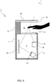
figure 5 est une vue en coupe schématique d'un dispositif d'acquisition d'empreintes digitales selon un deuxième mode de réalisation de l'invention. - La
figure 6 est une vue en coupe schématique d'un dispositif d'acquisition d'empreintes digitales selon un troisième mode de réalisation de l'invention. - Sur l'ensemble des figures, les éléments similaires portent des références identiques.
- En référence à la
figure 1 , un dispositif d'acquisition d'empreintes digitales 1 comprend un boîtier 2 définissant une cavité interne 4. - Le dispositif d'acquisition d'empreintes digitales 1 comprend en outre une source d'éclairage 6. La source d'éclairage 6 est agencée dans la cavité interne 4.
- La source d'éclairage 6 est configurée pour émettre une lumière dans le domaine visible et/ou dans un domaine non-visible (par exemple l'infrarouge).
- Par convention, la lumière émise par la source d'éclairage 6 est qualifiée dans le présente texte de « lumière d'éclairage », et, par contraste, une lumière émise par une source extérieure au dispositif d'acquisition d'empreintes est qualifiée de « lumière ambiante ».
- Dans le présent texte, un élément qualifié de « translucide » est à interpréter de manière générale comme tout milieu apte à être traversé par de la lumière, autrement dit un matériau non opaque, sans conditions supplémentaires (à moins que de telles conditions soient explicitement indiquées).
- Par ailleurs, un élément qualifié de « transparent » dans le présent texte est à interpréter comme un milieu qui est non seulement translucide mais qui laisse également aussi passer la visibilité. Autrement dit, il est possible de voir un objet nettement à travers un élément transparent, alors que ce n'est pas forcément le cas à travers un élément translucide.
- Le dispositif d'acquisition d'empreintes digitales 1 comprend une paroi transparente 8.
- La paroi transparente 8 forme une partie d'une paroi du boîtier 2, typiquement une paroi supérieure lorsque le dispositif 1 est dans une position d'utilisation. La paroi transparente 8 constitue une fenêtre entre la cavité interne 4 et l'extérieur du boîtier 2. La paroi transparente 8 présente une surface interne dans la cavité interne 4, et une surface externe à l'extérieur du boîtier 2, opposée à la surface interne. De préférence, la lumière d'éclairage ne peut sortir du boîtier 2 que par la paroi transparente 8.
- Les surfaces interne et externe de la paroi transparente 8 sont par exemple planes.
- La paroi transparente 8 est de préférence transparente et/ou homogène et/ou isotrope. Par exemple, la paroi transparente 8 est en verre.
- Le dispositif d'acquisition d'empreintes digitales 1 comprend par ailleurs une paroi translucide 10, agencée en regard et à distance de la paroi transparente 8 de sorte à ménager entre elles un espace 12 où un utilisateur peut placer au moins un de ses doigts.
- Par exemple, la hauteur de l'espace 12 ménagé, mesurée comme la distance séparant la paroi transparente 8 et la paroi translucide 10, est comprise entre 3 centimètres et 15 centimètres.
- La paroi transparente 8 s'étend entre la cavité interne 4 et l'espace 12.
- La paroi translucide 10 présente une surface interne orientée vers l'espace 12, et une surface externe opposée la surface interne. La surface externe débouche à l'extérieur du dispositif d'acquisition d'empreintes digitales 1, dans le sens où elle est visible par un utilisateur, en particulier par un utilisateur en train de placer au moins un de ses doigts dans l'espace 12.
- Les surfaces interne et externe de la paroi translucide 10 sont par exemple planes.
- La paroi translucide 10 est de préférence transparente et/ou homogène et/ou isotrope, mais ce n'est pas une obligation. Par exemple, la paroi translucide 10 est en polyméthacrylate de méthyle (plexiglas).
- Le dispositif d'acquisition d'empreintes digitales 1 comprend par ailleurs une partie de liaison 14 qui relie la paroi translucide 10 à la paroi transparente 8, et faisant office d'espaceur pour maintenir les deux parois 10, 12 à distance l'une de l'autre. Cette partie de liaison 14 peut faire partie du boîtier 2 où être un élément fixé sur le boîtier 2. La paroi translucide 10 s'étend en porte-à-faux depuis cette partie de liaison 14, en regard de la paroi transparente 8. La paroi translucide 10 forme ainsi une casquette.
- En référence à la
figure 2 , la partie de liaison 14 est agencée pour ménager un accès frontal 13a à l'espace 12 (qui se trouve sur lafigure 1 à droite de l'espace 12 tel que) ainsi que deux accès latéraux 13b, 13c à cet espace 12, qui sont opposés l'un à l'autre par rapport à l'accès frontal 13a. Autrement dit, l'espace 12 est situé entre les deux accès latéraux 13b, 13c, et est par ailleurs situé entre l'accès frontal 13a et la partie de liaison 14. Un utilisateur peut donc fait entrer un doigt dans l'espace 12 via l'accès frontal 13a ou via l'un des accès latéraux 13b, 13c. - Le dispositif d'acquisition d'empreintes digitales 1 est configuré pour que la lumière d'éclairage émise par la source d'éclairage 6 puisse traverser la paroi transparente 8 (sortant ainsi du boîtier 2), puis traverser l'espace 12 ménagé entre les deux parois translucides 8, 10, puis traverser la paroi translucide 10. Le dispositif 1 peut en particulier comprendre un système optique 16 configuré pour guider la lumière émise par la source d'éclairage 6 vers la paroi transparente 8. Dans le mode de réalisation représenté en
figure 1 , le système optique 16 est formé par un miroir, mais le système optique peut être plus complexe, et peut en variante être absent si la source d'éclairage 6 fait face à la paroi transparente 8. - Le dispositif d'acquisition d'empreintes digitales 1 comprend par ailleurs une caméra 18 configurée pour acquérir des images montrant l'empreinte digitale d'un doigt placé dans l'espace 12. Dans le présent texte, le terme « caméra » n'est pas limité à un moyen d'acquisition d'images sous forme de vidéo ; il est à interpréter dans un sens large, comme couvrant tout moyen d'acquisition d'image, y compris sous forme de vidéo ou d'image unique.
- La caméra 18 est agencée dans la cavité interne 4 du boîtier 2, de sorte à pouvoir recevoir de la lumière émanant de l'espace 12. La caméra 12 est en particulier configurée pour acquérir une image d'un doigt reçu dans l'espace 12.
- La caméra 18 est en particulier configurée pour réaliser une telle acquisition alors que le doigt est en suspension dans l'espace 12, sans que celui-ci ne touche le dispositif 1. Ceci est avantageux par rapport aux dispositifs d'acquisition d'empreintes digitales requérant la mise en contact d'un doigt sur une surface d'acquisition, car un tel contact est susceptible de déformer l'empreinte digitale, ce qui peut conduire à une acquisition imparfaite de cette empreinte.
- Le dispositif 1 peut comprendre un système optique (non illustré) pour rediriger la lumière émanant de l'espace 12 vers la caméra 18.
- La caméra 18 est apte à communiquer avec une unité de traitement d'image configurée pour mettre en œuvre toute ou partie d'un procédé d'authentification connu de l'état de la technique. Par exemple, ce procédé d'authentification peut avoir pour but d'identifier l'utilisateur ayant placé son doigt dans l'espace 12, ou de déterminer si cet utilisateur a le droit ou non d'accéder à un service ou une zone.
- Il est à noter que cette unité de traitement d'image peut être comprise dans le dispositif d'acquisition d'empreintes digitales 1, mais cela n'est aucunement requis car cette unité peut être située à l'extérieur de ce dispositif 1. Dans le second cas, le dispositif d'acquisition d'empreintes digitales 1 peut comprendre une interface de communication pour communiquer avec un dispositif externe, tel qu'un serveur, pourvu d'une telle unité de traitement d'image.
- Le dispositif d'acquisition d'empreintes digitales 1 comprend par ailleurs un système de polarisation. De manière générale, le système de polarisation est configuré pour
- polariser dans une première direction la lumière d'éclairage avant que la lumière d'éclairage n'atteigne l'espace 12,
- polariser dans une deuxième direction la lumière d'éclairage après que la lumière d'éclairage a traversé l'espace 12, la deuxième direction étant différente de la première direction,
- polariser dans la deuxième direction une lumière ambiante émanant de l'extérieur du dispositif 1 et se propageant vers la caméra 18, avant que la lumière ambiante n'atteigne l'espace 12, et
- polariser dans une troisième direction la lumière ambiante après que la lumière ambiante a traversé l'espace 12, la troisième direction étant différente de la deuxième direction.
- Dans le premier mode de réalisation représenté en
figure 1 , le système de polarisation comprend un premier polariseur 20 configuré pour polariser une lumière dans une première direction. - Le premier polariseur 20 est transparent. Le premier polariseur est agencé pour être traversé par la lumière d'éclairage émise par la source d'éclairage 6, et ce avant que la lumière d'éclairage n'atteigne l'espace 12.
- Le premier polariseur 20 est par ailleurs agencé pour être traversé par la lumière ambiante émise par une source extérieure au dispositif 1, et ce avant que cette lumière ambiante n'atteigne la caméra 18. Ainsi, dans ce mode de réalisation, la première direction et la troisième direction sont identique.
- Dans le premier mode de réalisation illustré sur la
figure 1 , le premier polariseur 20 délimite l'espace 12, de sorte que la lumière d'éclairage en provenance de la source d'éclairage 6 atteint l'espace 12 en sortant du premier polariseur 20. Ceci permet de garantir que le premier polariseur 20 est le dernier élément optique du dispositif qui modifie les propriétés de la lumière émanant de la source d'éclairage 6 avant que cette lumière n'atteigne l'espace 12. Si des éléments optiques du dispositif tels que la paroi transparente 8 étaient situés en aval du premier polariseur 20, ils pourraient altérer la polarisation de la lumière d'éclairage, si bien que la lumière d'éclairage ne serait plus parfaitement dans la première direction de polarisation lorsqu'elle atteint l'espace 12. Ce problème est évité dans ce premier mode de réalisation. - En pratique, le premier polariseur 20 est placé à l'extérieur du boîtier 2, entre la paroi transparente 8 est l'espace 12.
- Le premier polariseur 20 est fixé à la paroi transparente 8. Plus précisément, le premier polariseur 20 est fixé à la surface externe de la paroi transparente 8.
- Le premier polariseur 20 se présente par exemple sous la forme d'un film fixé sur la paroi transparente 8 à l'aide d'un adhésif.
- Dans le premier mode de réalisation illustré sur la
figure 1 , le système de polarisation comprend en outre un deuxième polariseur 22. Le premier polariseur 20 est configuré pour polariser la lumière dans une deuxième direction différente de la première polarisation, après que la lumière a traversé l'espace 12. L'espace 12 est situé entre le premier polariseur 20 et le deuxième polariseur 22. - Le deuxième polariseur est translucide, voire transparent.
- Le deuxième polariseur 22 délimite l'espace 12, de sorte que la lumière ambiante atteint l'espace 12 en sortant du deuxième polariseur 22. Ceci permet de garantir que le deuxième polariseur 22 est le dernier élément optique du dispositif qui modifie les propriétés de la lumière ambiante émanant de l'extérieur du dispositif 1, avant son entrée dans l'espace 12 d'éclairage.
- En pratique, le deuxième polariseur 22 est fixé à la paroi translucide 10. Plus précisément, le deuxième polariseur 22 est fixé à la surface interne de la paroi translucide 10. De la sorte, la paroi translucide 10 protège le deuxième polariseur 22 d'agressions extérieures au dispositif 1, qui risquerait de l'abîmer et ainsi altérer sa fonction de polarisation.
- Le deuxième polariseur 22 se présente par exemple sous la forme d'un film fixé sur la paroi translucide 10 à l'aide d'un adhésif.
- Le premier polariseur 20 et le deuxième polariseur 22 s'étendent parallèlement l'un à l'autre.
- Comme indiqué précédemment, la deuxième direction de polarisation est différente de la première direction de polarisation. De manière préférentielle, l'angle entre la première direction de polarisation et la deuxième direction de polarisation est compris entre 70 et 110 degrés, voire est compris entre 80 et 100 degrés. De manière encore plus préférentielle, la deuxième direction de polarisation est perpendiculaire à la première direction de polarisation.
- Un procédé d'acquisition d'empreintes digitales au moyen du dispositif d'acquisition d'empreintes digitales 1 comprend les étapes suivantes.
- On suppose que le dispositif d'acquisition d'empreintes digitales 1 est placé dans une position d'utilisation, dans laquelle la paroi transparente 8 forme une portion de paroi supérieure du boîtier 2 et dans laquelle la paroi translucide 10 se trouve au-dessus de la paroi transparente 8.
- Un utilisateur se place devant le dispositif 1, et en particulier en face de l'accès frontal 13a à l'espace 12. Le dispositif 1 est typiquement placé à une hauteur permettant à l'utilisateur de surplomber le dispositif 1, de sorte que le deuxième polariseur 20 se trouve entre l'espace 12 et les yeux de l'utilisateur.
- L'utilisateur fait pénétrer au moins une de ses doigts dans l'espace 12 ménagé entre les polariseurs 20 et 22, de sorte que l'empreinte digitale d'un doigt soit en vue de la caméra 18.
- L'utilisateur peut en particulier faire pénétrer un doigt par un des accès latéraux à l'espace 12, par exemple l'accès latéral 13b, et le déplacer vers l'autre accès latéral 13c selon une trajectoire rectiligne comme représenté en
figure 2 . - La source d'éclairage 6 émet la lumière d'éclairage discutée précédemment, afin d'éclairer l'espace 12 et en particulier le doigt que l'utilisateur y a placé. L'émission de la lumière d'éclairage est par exemple déclenchée sur une détection de présence du doigt dans le champ de vision de la caméra 18, à l'aide de moyens de détection adéquats du dispositif d'acquisition d'empreintes digitales 1.
- La lumière d'éclairage est émise typiquement sous la forme d'une succession de flashs brefs et puissants.
- La lumière d'éclairage se propage dans la cavité interne 4, est redirigée vers la paroi transparente 8 par le système optique 16, et traverse la paroi transparente 8. La lumière d'éclairage traverse par ailleurs le premier polariseur 20, lequel polarise la lumière d'éclairage dans la première direction. Le premier polariseur 20 agit sur la lumière d'éclairage comme un filtre : toute direction de polarisation éventuellement présente dans la lumière d'éclairage en amont du premier polariseur 20 est éliminée lors de la traversée du premier polariseur 20 par cette lumière, à l'exception de la première direction.
- Une fois polarisée dans la première direction par le premier polariseur 20, la lumière d'éclairage se propage dans l'espace 12.
- Une partie de la lumière d'éclairage polarisée dans la première direction éclaire en particulier l'empreinte digitale du doigt placé dans l'espace 12. Cette partie de la lumière d'éclairage est réfléchie par le doigt de l'utilisateur, et pénètre à nouveau dans le boîtier 2 en traversant le premier polariseur 20 et la paroi transparente 8, avant d'atteindre la caméra 18.
- La caméra 18 acquiert une image montrant l'empreinte digitale du doigt reçu dans l'espace 12. Cette image peut ensuite être utilisée dans le cadre du procédé d'authentification cité précédemment.
- Pendant cette acquisition, il n'est pas nécessaire que le doigt soit mis en contact avec le dispositif 1, en particulier avec la paroi transparente 8 ou le premier polariseur 20.
- Comme l'utilisateur peut voir l'espace 12 à travers la paroi translucide 10 et à travers le deuxième polariseur 22, l'utilisateur a pu positionner très facilement son doigt dans l'espace 12 en regard de la caméra 18, ce a permis de raccourcir la durée de mise en œuvre du procédé. Par contraste, un utilisateur incapable de visualiser où se trouve son doigt par rapport à la paroi transparente 8 aurait tendance à hésiter ou en tout cas tâtonner pour placer correctement son doigt, ce qui ne pourrait que retarder le déclenchement de l'étape d'acquisition ou conduire à l'obtention d'une image ne montrant pas l'empreinte digitale correctement, compromettant ainsi le bon fonctionnement du procédé qui exploite ensuite cette image.
- Bien entendu, l'utilisation de la source d'éclairage 6 améliore la lisibilité de l'empreinte digitale dans l'image acquise par la caméra 18. Le premier polariseur 20 améliore en outre la dynamique de cette image.
- On a vu précédemment qu'une portion de la lumière d'éclairage polarisée dans la première direction a été réfléchie par le doigt. Une partie restante de la lumière d'éclairage polarisée dans la première direction, non bloquée par le doigt ou tout autre éventuel obstacle, traverse entièrement l'espace 12 en direction du deuxième polariseur 22 et de la paroi translucide 10, puis traverse le deuxième polariseur 22. Cette partie restante subit donc une nouvelle polarisation, mais cette fois dans la deuxième direction, différente de la première direction. Ainsi, le deuxième polariseur applique à la partie restante de la lumière d'éclairage un second filtrage éliminant une grande partie de la puissance transportée par cette lumière. En conséquence, l'utilisateur regardant en direction de l'espace 12 à travers le deuxième polariseur 22 n'est pas ébloui par la lumière d'éclairage.
- On a représenté en
figure 3 de manière schématique un exemple de double polarisation de la lumière d'éclairage réalisée par les deux polariseurs 20 et 22. Dans cet exemple, le premier polariseur 20 polarise la lumière d'éclairage dans une direction parallèle à un axe X, et le deuxième polariseur polarise la lumière d'éclairage dans une direction parallèle à un axe Y perpendiculaire à l'axe X. Dans cette situation de perpendicularité, la lumière d'éclairage est complètement éliminée par les deux polariseurs 20, 22 avant d'atteindre l'utilisateur. - Considérons à présent une lumière ambiante émise par une source externe au dispositif d'acquisition d'empreintes digitales 1. Une partie de cette lumière ambiante peut traverser la paroi translucide 10 et le deuxième polariseur 22, puis traverser l'espace 12, traverser la paroi transparente 8 et le première polariseur (en supposant qu'elle n'est pas bloquée par un doigt ou tout autre obstacle placé dans l'espace 12). Cette partie de la lumière ambiante subit donc deux polarisations successives avant d'atteindre la caméra 18 : une polarisation dans la deuxième direction, puis une polarisation dans la première direction. De la sorte, une grande partie de la puissance de la lumière ambiante est éliminée avant d'atteindre la caméra 18, ce qui a pour conséquence de limiter voire éliminer les perturbations que causerait la lumière ambiante sur l'acquisition d'image réalisée par la caméra 18.
- On a représenté en
figure 4 de manière schématique la double polarisation de la lumière ambiante par les deux polariseurs 20 et 22 dans le même exemple de réalisation que celui de lafigure 3 . Dans cet exemple, la lumière ambiante est complètement éliminée par les deux polariseurs 20, 22 avant d'atteindre la caméra 6. - La lumière ambiante permet en outre à l'utilisateur regardant en direction de la surface supérieure de la paroi translucide 10 de pouvoir contempler l'espace 12 où il a placé son doigt.
- En définitive, les deux polariseurs 20, 22 permettent d'atteindre un double objectif : réduire les risques d'éblouir un utilisateur veillant à bien positionner son doigt en vue de l'acquisition de son empreinte digitale par le dispositif 1, et les risques d'éblouir la caméra 18. Dans le cas particulier où la première direction de polarisation et la deuxième direction de polarisation sont perpendiculaires, l'utilisateur et la caméra 18 voient tous deux le doigt reçu dans l'espace, mais ne se voient pas mutuellement, ce qui est très avantageux car les risques d'éblouissement précités sont totalement éliminés.
- Il a été pris dans ce qui précède l'exemple de l'acquisition de l'image d'un doigt d'un utilisateur. Toutefois, le dispositif 1 peut tout à fait être utilisé pour acquérir une ou plusieurs images d'empreintes digitales de plusieurs doigts de l'utilisateur. Pour cela, l'utilisateur peut faire entrer plusieurs de ses doigts dans l'espace 12, de sorte que les doigts traversent ensemble l'espace 12 en allant d'un accès latéral à l'autre, en suivant une trajectoire rectiligne comme cela est représenté par une flèche en pointillés sur la
figure 2 . Au cours de cette traversée, les doigts sont successivement ou simultanément en vue de la caméra 18, si bien qu'une ou plusieurs images les montrant peuvent être acquises par la caméra 18. - Est représenté en
figure 5 un deuxième mode de réalisation du dispositif 1, qui diffère du premier mode de réalisation représenté enfigure 1 par la forme de son système de polarisation : en effet, le premier polariseur 20 est situé dans la cavité interne 4 du boîtier 2. Ceci permet de protéger le premier polariseur 20 d'agressions en provenance de l'extérieur du boîtier 2. Par exemple, le premier polariseur 20 est fixé à la surface interne de la paroi transparente 8. En contrepartie de cet effet protecteur, le filtrage de lumière réalisée par les deux polarisateurs 20 et 22 peut être légèrement moins performant que dans le premier mode de réalisation, car la première paroi translucide peut « dépolariser » la lumière d'éclairage ayant été polarisée dans la première direction, avant son entrée dans l'espace 12 et sa polarisation ultérieure par le deuxième polariseur 22. - Dans les deux modes de réalisation décrits précédemment, le système de polarisation ne comprend que deux polariseurs. En particulier, le premier polariseur 20 se charge non seulement de polariser la lumière émanant de la source d'éclairage 6, mais également la lumière allant vers la caméra 6. Cette configuration présente l'avantage d'être simple de fabrication.
- Est représenté en
figure 6 un troisième mode de réalisation du dispositif 1, qui diffère du deuxième mode de réalisation par le fait que le système de polarisation comprend trois polariseurs. Plus précisément, le premier polariseur 20 du deuxième mode de réalisation est remplacé dans le troisième mode de réalisation par une paire de polariseurs 24, 26 distincts. - D'une part, le polariseur 24 est configuré pour polariser dans la première direction la lumière émanant de la source d'éclairage 6 avant que celle-ci n'atteigne l'espace 12. Le polariseur 24 est agencé dans la cavité interne 4. Le polariseur 24 est fixé par exemple à la source d'éclairage 6, mais peut en variante être à distance de celle-ci. Le polariseur 24 est translucide, voire transparent.
- D'autre part, le polariseur 26 est configuré pour polariser la lumière en provenance de l'espace 4 dans une troisième direction, avant que celle-ci n'atteigne la caméra. Le polariseur 26 est également agencé dans la cavité interne 4. Le polariseur 26 est fixé par exemple à la caméra 18, mais peut en variante être à distance de celle-ci. Le polariseur 26 est transparent.
- La troisième direction est de préférence identique à la première direction, afin d'optimiser les performances d'atténuation du système de polarisation, mais pas obligatoirement.
- Un avantage du troisième mode de réalisation est que la paire de polariseurs 24, 26 peuvent être de dimensions réduites. Ainsi le coût de la paire de polariseurs 24, 26 peut être inférieur au coût du polariseur 20.
- D'autres modes de réalisation du dispositif d'acquisition d'empreintes digitales 1 non illustrés sont également envisageables. Ces modes de réalisation peuvent comprendre les caractéristiques exposées ci-dessous.
- Le premier polariseur 20 peut être positionné dans le boîtier 2, à distance de la paroi transparente 8.
- Le deuxième polariseur 22 peut par ailleurs être fixé sur la surface externe de la paroi translucide 10, ou à distance de la paroi translucide 10.
- Il n'est pas du tout obligatoire que les deux polariseurs soient alignés, pourvu qu'ils puissent être successivement traversés par la lumière d'éclairage émise par la source d'éclairage 6, et être successivement traversés par de la lumière ambiante émanant de l'extérieur, avant que cette lumière ne puisse atteindre la caméra 18.
- Dans les modes de réalisation représenté sur les
figures 1 et5 , les polariseurs 20, 22 et les deux parois translucides 8, 10 constituent quatre éléments translucides qui sont successivement traversés par la lumière d'éclairage, et qui peuvent être successivement traversés par une lumière ambiante émanant de l'extérieur du dispositif 1. Toutefois, il est entendu que le dispositif 1 peut parfaitement ne comprendre que deux éléments translucides assurant les fonctions de polarisation précitées et par ailleurs délimitant entre elles l'espace 12 où les doigts d'utilisateurs sont reçus. - Dans ce qui précède, il a en outre été supposé que le dispositif 1 est du type sans contact, dans le sens où il n'est pas spécialement requis qu'un doigt soit mis en contact avec le dispositif 1 au cours de l'acquisition. Toutefois, le dispositif 1 pourrait en variante être du type avec contact.
Claims (13)
- Dispositif (1) d'acquisition d'empreintes digitales, le dispositif (1) comprenant :- un espace (12) pour recevoir un doigt d'un utilisateur,- une source d'éclairage (6) configurée pour émettre une lumière d'éclairage éclairant l'espace (12),- une caméra (18) configurée pour acquérir une image d'une empreinte digitale du doigt, lorsque le doigt est reçu dans l'espace (12),le dispositif étant caractérisé en ce qu'il comprend un système de polarisation (20, 22, 24, 26) configuré pour :- polariser dans une première direction la lumière d'éclairage avant que la lumière d'éclairage n'atteigne l'espace (12),- polariser dans une deuxième direction la lumière d'éclairage après que la lumière d'éclairage a traversé l'espace (12), la deuxième direction étant différente de la première direction,- polariser dans la deuxième direction une lumière ambiante émanant de l'extérieur du dispositif (1) et se propageant vers la caméra (18), avant que la lumière ambiante n'atteigne l'espace (12), et- polariser dans une troisième direction la lumière ambiante après que la lumière ambiante a traversé l'espace (12), la troisième direction étant différente de la deuxième direction, dans lequel le système de polarisation (10, 20) comprend un premier polariseur (20) configuré pour :- polariser la lumière d'éclairage dans la première direction avant que la lumière d'éclairage n'atteigne l'espace (12), et- polariser la lumière ambiante dans la première direction après que la lumière ambiante a traversé l'espace (12), et avant que la lumière ambiante n'atteigne la caméra.
- Dispositif (1) selon la revendication précédente, dans lequel la deuxième direction est perpendiculaire à la première direction.
- Dispositif (1) selon l'une des revendications précédentes, dans lequel la troisième direction et la première direction sont identiques.
- Dispositif (1) selon la revendication précédente, dans lequel le premier polariseur (20) délimite l'espace (12), de sorte que la lumière d'éclairage atteint l'espace (12) en sortant du premier polariseur (20).
- Dispositif (1) selon l'une des revendications précédentes, comprenant un boîtier (2) définissant une cavité (4) contenant la source d'éclairage (6), et une paroi transparente (8) formant une fenêtre entre la cavité (4) et l'espace (12) pour recevoir le doigt, dans lequel le premier polariseur (20) est fixé à la paroi translucide (8).
- Dispositif (1) selon l'une des revendications précédentes, comprenant un boîtier (2) définissant une cavité (4) contenant la source d'éclairage (6), et une paroi transparente (8) formant une fenêtre entre la cavité (4) et l'espace (12) pour recevoir le doigt, dans lequel le premier polariseur (20) est agencé dans le boîtier (2).
- Dispositif (1) selon l'une des revendications précédentes, comprenant un boîtier (2) définissant une cavité (4) contenant la source d'éclairage (6), dans lequel le premier polariseur (20) forme une fenêtre transparente séparant la cavité (4) et l'espace (12) pour recevoir le doigt.
- Dispositif (1) selon l'une des revendications précédentes, dans lequel le système de polarisation comprend un deuxième polariseur (22) configuré pour :- polariser la lumière d'éclairage dans la deuxième direction après que la lumière d'éclairage a traversé l'espace (12), et- polariser la lumière ambiante dans la deuxième direction avant que la lumière ambiante n'atteigne l'espace (12).
- Dispositif (1) selon la revendication précédente, dans lequel le deuxième polariseur (22) délimite l'espace (12), de sorte que la lumière ambiante atteint l'espace (12) en sortant du deuxième polariseur (22).
- Dispositif (1) selon l'une des revendications 8 et 9, dans lequel le premier polariseur (20) et le deuxième polariseur (22) s'étendent parallèlement l'un à l'autre.
- Dispositif (1) selon l'une des revendications 8 à 10, comprenant une deuxième paroi translucide (10), le deuxième polariseur (22) étant fixé à la deuxième paroi translucide (10).
- Dispositif (1) selon l'une des revendications précédentes, définissant un accès frontal (13a) à l'espace (12) et deux accès latéraux (13b, 13c) à l'espace (12) qui sont opposés l'un à l'autre par rapport à l'accès frontal (13a), de sorte à permettre à l'utilisateur de déplacer le doigt suivant une trajectoire rectiligne, en faisant entrer le doigt dans l'espace (12) par l'un des deux accès latéraux (13b), et en faisant ressortir le doigt de l'espace par l'autre accès latéral (13c).
- Dispositif (1) selon l'une des revendications précédentes, comprenant un boîtier (2) définissant une cavité (4) contenant la source d'éclairage (6), et une paroi transparente (8) formant une fenêtre entre la cavité (4) et l'espace (12) pour recevoir le doigt, dans lequel la caméra est configurée pour acquérir l'image de l'empreinte digitale du doigt, lorsque le doigt est posé sur la paroi transparente (8).
Applications Claiming Priority (1)
| Application Number | Priority Date | Filing Date | Title |
|---|---|---|---|
| FR2104541A FR3122507B1 (fr) | 2021-04-30 | 2021-04-30 | Dispositif d’acquisition d’empreintes digitales |
Publications (3)
| Publication Number | Publication Date |
|---|---|
| EP4083829A1 true EP4083829A1 (fr) | 2022-11-02 |
| EP4083829C0 EP4083829C0 (fr) | 2024-06-19 |
| EP4083829B1 EP4083829B1 (fr) | 2024-06-19 |
Family
ID=76730735
Family Applications (1)
| Application Number | Title | Priority Date | Filing Date |
|---|---|---|---|
| EP22170166.7A Active EP4083829B1 (fr) | 2021-04-30 | 2022-04-27 | Dispositif d' acquisition d' empreintes digitales |
Country Status (3)
| Country | Link |
|---|---|
| US (1) | US11854295B2 (fr) |
| EP (1) | EP4083829B1 (fr) |
| FR (1) | FR3122507B1 (fr) |
Families Citing this family (1)
| Publication number | Priority date | Publication date | Assignee | Title |
|---|---|---|---|---|
| DE102020131513B3 (de) * | 2020-11-27 | 2022-01-27 | JENETRIC GmbH | Vorrichtung und Verfahren zur berührungslosen optischen Abbildung eines ausgewählten Oberflächenbereiches einer Hand |
Citations (2)
| Publication number | Priority date | Publication date | Assignee | Title |
|---|---|---|---|---|
| DE202004012606U1 (de) * | 2004-08-12 | 2004-11-11 | Tbs Holding Ag | Vorrichtung zur Vermeidung von Blendung und Verbesserung der Bildqualität bei der Erkennung biometrischer Daten |
| JP2011108128A (ja) * | 2009-11-20 | 2011-06-02 | Secom Co Ltd | 認証装置 |
Family Cites Families (1)
| Publication number | Priority date | Publication date | Assignee | Title |
|---|---|---|---|---|
| JP7438766B2 (ja) * | 2019-04-25 | 2024-02-27 | 恵和株式会社 | 指紋認証装置を備えたoledディスプレイ用の保護フィルム |
-
2021
- 2021-04-30 FR FR2104541A patent/FR3122507B1/fr active Active
-
2022
- 2022-04-27 EP EP22170166.7A patent/EP4083829B1/fr active Active
- 2022-04-29 US US17/661,469 patent/US11854295B2/en active Active
Patent Citations (2)
| Publication number | Priority date | Publication date | Assignee | Title |
|---|---|---|---|---|
| DE202004012606U1 (de) * | 2004-08-12 | 2004-11-11 | Tbs Holding Ag | Vorrichtung zur Vermeidung von Blendung und Verbesserung der Bildqualität bei der Erkennung biometrischer Daten |
| JP2011108128A (ja) * | 2009-11-20 | 2011-06-02 | Secom Co Ltd | 認証装置 |
Also Published As
| Publication number | Publication date |
|---|---|
| FR3122507B1 (fr) | 2024-10-25 |
| US11854295B2 (en) | 2023-12-26 |
| FR3122507A1 (fr) | 2022-11-04 |
| EP4083829C0 (fr) | 2024-06-19 |
| EP4083829B1 (fr) | 2024-06-19 |
| US20220351536A1 (en) | 2022-11-03 |
Similar Documents
| Publication | Publication Date | Title |
|---|---|---|
| EP3004963B1 (fr) | Système de vision oculaire avec guide optique positionnable dans deux positions | |
| EP3388975B1 (fr) | Dispositif de capture d'une empreinte d'une partie corporelle | |
| EP2364456B1 (fr) | Dispositif de guidage optique d'un faisceau lumineux | |
| FR2623789A1 (fr) | Dispositif de controle des fonds de bouteilles | |
| EP2695017A1 (fr) | Dispositif de guidage optique et procédé de fabrication d'un tel dispositif | |
| FR2554261A1 (fr) | Dispositif sensitif d'affichage comportant un ecran a balayage | |
| FR2978564A1 (fr) | Dispositif pour la polarisation d'une sequence video a visionner en stereoscopie | |
| EP4083829B1 (fr) | Dispositif d' acquisition d' empreintes digitales | |
| CA2301733C (fr) | Procede et dispositif de lecture de reliefs portes par un recipient transparent ou translucide | |
| CA3234654A1 (fr) | Dispositif d'imagerie infrarouge | |
| EP3491330B1 (fr) | Systèmes et procédés d'imagerie interférentielle plein champ | |
| EP4105897B1 (fr) | Dispositif de capture biométrique | |
| WO2018109350A1 (fr) | Dispositif de protection employé dans un système de détection par imagerie sans lentille et système de détection par imagerie sans lentille employant ledit dispositif | |
| FR3070637A1 (fr) | Palette tactile a effet optique sur volant de conduite pour detection de doigt | |
| EP0880104A1 (fr) | Capteur optique d'empreinte digitale à éclairage impulsionnel | |
| FR3113152A1 (fr) | Terminal biométrique, en particulier de contrôle d’accès | |
| EP4672771A1 (fr) | Équipement électronique a volet translucide et procédé de gestion associé | |
| EP0851380A1 (fr) | Capteur optique d'empreinte digitale | |
| EP2808734B1 (fr) | Ecran et dispositif d'affichage en rétroprojection | |
| WO2025132446A1 (fr) | Système optique comprenant un émetteur laser et un écran translucide | |
| EP4575631A1 (fr) | Detection de la position d'un volet de camera par retroeclairage | |
| EP3919895A1 (fr) | Systeme de visualisation de bulles sous une feuille adhesive | |
| FR2948477A1 (fr) | Dispositif de capture d'une empreinte d'une partie corporelle | |
| FR2907300A1 (fr) | Installation de surveillance | |
| WO2015185837A9 (fr) | Dispositif optique pour l'observation d'un objet, minimisant le phenomene de reflexion interne |
Legal Events
| Date | Code | Title | Description |
|---|---|---|---|
| PUAI | Public reference made under article 153(3) epc to a published international application that has entered the european phase |
Free format text: ORIGINAL CODE: 0009012 |
|
| STAA | Information on the status of an ep patent application or granted ep patent |
Free format text: STATUS: THE APPLICATION HAS BEEN PUBLISHED |
|
| AK | Designated contracting states |
Kind code of ref document: A1 Designated state(s): AL AT BE BG CH CY CZ DE DK EE ES FI FR GB GR HR HU IE IS IT LI LT LU LV MC MK MT NL NO PL PT RO RS SE SI SK SM TR |
|
| STAA | Information on the status of an ep patent application or granted ep patent |
Free format text: STATUS: REQUEST FOR EXAMINATION WAS MADE |
|
| 17P | Request for examination filed |
Effective date: 20230413 |
|
| RBV | Designated contracting states (corrected) |
Designated state(s): AL AT BE BG CH CY CZ DE DK EE ES FI FR GB GR HR HU IE IS IT LI LT LU LV MC MK MT NL NO PL PT RO RS SE SI SK SM TR |
|
| STAA | Information on the status of an ep patent application or granted ep patent |
Free format text: STATUS: EXAMINATION IS IN PROGRESS |
|
| 17Q | First examination report despatched |
Effective date: 20230714 |
|
| P01 | Opt-out of the competence of the unified patent court (upc) registered |
Effective date: 20230919 |
|
| GRAP | Despatch of communication of intention to grant a patent |
Free format text: ORIGINAL CODE: EPIDOSNIGR1 |
|
| STAA | Information on the status of an ep patent application or granted ep patent |
Free format text: STATUS: GRANT OF PATENT IS INTENDED |
|
| RIC1 | Information provided on ipc code assigned before grant |
Ipc: G06V 40/13 20220101ALI20231013BHEP Ipc: A61B 5/1172 20160101ALI20231013BHEP Ipc: G06F 21/32 20130101AFI20231013BHEP |
|
| INTG | Intention to grant announced |
Effective date: 20231110 |
|
| GRAJ | Information related to disapproval of communication of intention to grant by the applicant or resumption of examination proceedings by the epo deleted |
Free format text: ORIGINAL CODE: EPIDOSDIGR1 |
|
| STAA | Information on the status of an ep patent application or granted ep patent |
Free format text: STATUS: EXAMINATION IS IN PROGRESS |
|
| GRAP | Despatch of communication of intention to grant a patent |
Free format text: ORIGINAL CODE: EPIDOSNIGR1 |
|
| STAA | Information on the status of an ep patent application or granted ep patent |
Free format text: STATUS: GRANT OF PATENT IS INTENDED |
|
| INTC | Intention to grant announced (deleted) | ||
| INTG | Intention to grant announced |
Effective date: 20240215 |
|
| GRAS | Grant fee paid |
Free format text: ORIGINAL CODE: EPIDOSNIGR3 |
|
| GRAA | (expected) grant |
Free format text: ORIGINAL CODE: 0009210 |
|
| STAA | Information on the status of an ep patent application or granted ep patent |
Free format text: STATUS: THE PATENT HAS BEEN GRANTED |
|
| AK | Designated contracting states |
Kind code of ref document: B1 Designated state(s): AL AT BE BG CH CY CZ DE DK EE ES FI FR GB GR HR HU IE IS IT LI LT LU LV MC MK MT NL NO PL PT RO RS SE SI SK SM TR |
|
| REG | Reference to a national code |
Ref country code: GB Ref legal event code: FG4D Free format text: NOT ENGLISH |
|
| REG | Reference to a national code |
Ref country code: CH Ref legal event code: EP |
|
| REG | Reference to a national code |
Ref country code: DE Ref legal event code: R096 Ref document number: 602022003987 Country of ref document: DE |
|
| U01 | Request for unitary effect filed |
Effective date: 20240619 |
|
| P04 | Withdrawal of opt-out of the competence of the unified patent court (upc) registered |
Free format text: CASE NUMBER: APP_37725/2024 Effective date: 20240624 |
|
| U07 | Unitary effect registered |
Designated state(s): AT BE BG DE DK EE FI FR IT LT LU LV MT NL PT SE SI Effective date: 20240701 |
|
| PG25 | Lapsed in a contracting state [announced via postgrant information from national office to epo] |
Ref country code: HR Free format text: LAPSE BECAUSE OF FAILURE TO SUBMIT A TRANSLATION OF THE DESCRIPTION OR TO PAY THE FEE WITHIN THE PRESCRIBED TIME-LIMIT Effective date: 20240619 |
|
| PG25 | Lapsed in a contracting state [announced via postgrant information from national office to epo] |
Ref country code: GR Free format text: LAPSE BECAUSE OF FAILURE TO SUBMIT A TRANSLATION OF THE DESCRIPTION OR TO PAY THE FEE WITHIN THE PRESCRIBED TIME-LIMIT Effective date: 20240920 |
|
| PG25 | Lapsed in a contracting state [announced via postgrant information from national office to epo] |
Ref country code: HR Free format text: LAPSE BECAUSE OF FAILURE TO SUBMIT A TRANSLATION OF THE DESCRIPTION OR TO PAY THE FEE WITHIN THE PRESCRIBED TIME-LIMIT Effective date: 20240619 Ref country code: GR Free format text: LAPSE BECAUSE OF FAILURE TO SUBMIT A TRANSLATION OF THE DESCRIPTION OR TO PAY THE FEE WITHIN THE PRESCRIBED TIME-LIMIT Effective date: 20240920 Ref country code: RS Free format text: LAPSE BECAUSE OF FAILURE TO SUBMIT A TRANSLATION OF THE DESCRIPTION OR TO PAY THE FEE WITHIN THE PRESCRIBED TIME-LIMIT Effective date: 20240919 |
|
| P05 | Withdrawal of opt-out of the competence of the unified patent court (upc) changed |
Free format text: CASE NUMBER: APP_37725/2024 Effective date: 20240701 |
|
| PG25 | Lapsed in a contracting state [announced via postgrant information from national office to epo] |
Ref country code: PL Free format text: LAPSE BECAUSE OF FAILURE TO SUBMIT A TRANSLATION OF THE DESCRIPTION OR TO PAY THE FEE WITHIN THE PRESCRIBED TIME-LIMIT Effective date: 20240619 |
|
| PG25 | Lapsed in a contracting state [announced via postgrant information from national office to epo] |
Ref country code: CZ Free format text: LAPSE BECAUSE OF FAILURE TO SUBMIT A TRANSLATION OF THE DESCRIPTION OR TO PAY THE FEE WITHIN THE PRESCRIBED TIME-LIMIT Effective date: 20240619 |
|
| PG25 | Lapsed in a contracting state [announced via postgrant information from national office to epo] |
Ref country code: RO Free format text: LAPSE BECAUSE OF FAILURE TO SUBMIT A TRANSLATION OF THE DESCRIPTION OR TO PAY THE FEE WITHIN THE PRESCRIBED TIME-LIMIT Effective date: 20240619 Ref country code: SK Free format text: LAPSE BECAUSE OF FAILURE TO SUBMIT A TRANSLATION OF THE DESCRIPTION OR TO PAY THE FEE WITHIN THE PRESCRIBED TIME-LIMIT Effective date: 20240619 |
|
| PG25 | Lapsed in a contracting state [announced via postgrant information from national office to epo] |
Ref country code: ES Free format text: LAPSE BECAUSE OF FAILURE TO SUBMIT A TRANSLATION OF THE DESCRIPTION OR TO PAY THE FEE WITHIN THE PRESCRIBED TIME-LIMIT Effective date: 20240619 Ref country code: SM Free format text: LAPSE BECAUSE OF FAILURE TO SUBMIT A TRANSLATION OF THE DESCRIPTION OR TO PAY THE FEE WITHIN THE PRESCRIBED TIME-LIMIT Effective date: 20240619 |
|
| PG25 | Lapsed in a contracting state [announced via postgrant information from national office to epo] |
Ref country code: SM Free format text: LAPSE BECAUSE OF FAILURE TO SUBMIT A TRANSLATION OF THE DESCRIPTION OR TO PAY THE FEE WITHIN THE PRESCRIBED TIME-LIMIT Effective date: 20240619 Ref country code: SK Free format text: LAPSE BECAUSE OF FAILURE TO SUBMIT A TRANSLATION OF THE DESCRIPTION OR TO PAY THE FEE WITHIN THE PRESCRIBED TIME-LIMIT Effective date: 20240619 Ref country code: RO Free format text: LAPSE BECAUSE OF FAILURE TO SUBMIT A TRANSLATION OF THE DESCRIPTION OR TO PAY THE FEE WITHIN THE PRESCRIBED TIME-LIMIT Effective date: 20240619 Ref country code: PL Free format text: LAPSE BECAUSE OF FAILURE TO SUBMIT A TRANSLATION OF THE DESCRIPTION OR TO PAY THE FEE WITHIN THE PRESCRIBED TIME-LIMIT Effective date: 20240619 Ref country code: ES Free format text: LAPSE BECAUSE OF FAILURE TO SUBMIT A TRANSLATION OF THE DESCRIPTION OR TO PAY THE FEE WITHIN THE PRESCRIBED TIME-LIMIT Effective date: 20240619 Ref country code: CZ Free format text: LAPSE BECAUSE OF FAILURE TO SUBMIT A TRANSLATION OF THE DESCRIPTION OR TO PAY THE FEE WITHIN THE PRESCRIBED TIME-LIMIT Effective date: 20240619 |
|
| RAP2 | Party data changed (patent owner data changed or rights of a patent transferred) |
Owner name: IDEMIA PUBLIC SECURITY FRANCE |
|
| U1K | Transfer of rights of the unitary patent after the registration of the unitary effect |
Owner name: IDEMIA PUBLIC SECURITY FRANCE; FR |
|
| U1N | Appointed representative for the unitary patent procedure changed after the registration of the unitary effect |
Representative=s name: IPS; FR |
|
| U20 | Renewal fee for the european patent with unitary effect paid |
Year of fee payment: 4 Effective date: 20250319 |
|
| PLBE | No opposition filed within time limit |
Free format text: ORIGINAL CODE: 0009261 |
|
| STAA | Information on the status of an ep patent application or granted ep patent |
Free format text: STATUS: NO OPPOSITION FILED WITHIN TIME LIMIT |
|
| 26N | No opposition filed |
Effective date: 20250320 |
|
| PGFP | Annual fee paid to national office [announced via postgrant information from national office to epo] |
Ref country code: IS Payment date: 20250414 Year of fee payment: 4 |
|
| REG | Reference to a national code |
Ref country code: CH Ref legal event code: H13 Free format text: ST27 STATUS EVENT CODE: U-0-0-H10-H13 (AS PROVIDED BY THE NATIONAL OFFICE) Effective date: 20251125 |
|
| PG25 | Lapsed in a contracting state [announced via postgrant information from national office to epo] |
Ref country code: MC Free format text: LAPSE BECAUSE OF FAILURE TO SUBMIT A TRANSLATION OF THE DESCRIPTION OR TO PAY THE FEE WITHIN THE PRESCRIBED TIME-LIMIT Effective date: 20240619 |
|
| PG25 | Lapsed in a contracting state [announced via postgrant information from national office to epo] |
Ref country code: CH Free format text: LAPSE BECAUSE OF NON-PAYMENT OF DUE FEES Effective date: 20250430 |
|
| PGFP | Annual fee paid to national office [announced via postgrant information from national office to epo] |
Ref country code: GB Payment date: 20260320 Year of fee payment: 5 |
|
| PG25 | Lapsed in a contracting state [announced via postgrant information from national office to epo] |
Ref country code: IE Free format text: LAPSE BECAUSE OF NON-PAYMENT OF DUE FEES Effective date: 20250427 |
|
| PGFP | Annual fee paid to national office [announced via postgrant information from national office to epo] |
Ref country code: NO Payment date: 20260320 Year of fee payment: 5 |