EP4084032B1 - Vakuumschalteranordnung für einen leistungsumschalter, leistungsumschalter für einen transformatorlaststufenschalter und transformatorlaststufenschalter - Google Patents
Vakuumschalteranordnung für einen leistungsumschalter, leistungsumschalter für einen transformatorlaststufenschalter und transformatorlaststufenschalter Download PDFInfo
- Publication number
- EP4084032B1 EP4084032B1 EP21170940.7A EP21170940A EP4084032B1 EP 4084032 B1 EP4084032 B1 EP 4084032B1 EP 21170940 A EP21170940 A EP 21170940A EP 4084032 B1 EP4084032 B1 EP 4084032B1
- Authority
- EP
- European Patent Office
- Prior art keywords
- vacuum interrupter
- disc
- guiding tube
- piston
- channel
- Prior art date
- Legal status (The legal status is an assumption and is not a legal conclusion. Google has not performed a legal analysis and makes no representation as to the accuracy of the status listed.)
- Active
Links
Images


Classifications
-
- H—ELECTRICITY
- H01—ELECTRIC ELEMENTS
- H01F—MAGNETS; INDUCTANCES; TRANSFORMERS; SELECTION OF MATERIALS FOR THEIR MAGNETIC PROPERTIES
- H01F29/00—Variable transformers or inductances not covered by group H01F21/00
- H01F29/02—Variable transformers or inductances not covered by group H01F21/00 with tappings on coil or winding; with provision for rearrangement or interconnection of windings
- H01F29/04—Variable transformers or inductances not covered by group H01F21/00 with tappings on coil or winding; with provision for rearrangement or interconnection of windings having provision for tap-changing without interrupting the load current
-
- H—ELECTRICITY
- H01—ELECTRIC ELEMENTS
- H01H—ELECTRIC SWITCHES; RELAYS; SELECTORS; EMERGENCY PROTECTIVE DEVICES
- H01H3/00—Mechanisms for operating contacts
- H01H3/32—Driving mechanisms, i.e. for transmitting driving force to the contacts
- H01H3/42—Driving mechanisms, i.e. for transmitting driving force to the contacts using cam or eccentric
-
- H—ELECTRICITY
- H01—ELECTRIC ELEMENTS
- H01H—ELECTRIC SWITCHES; RELAYS; SELECTORS; EMERGENCY PROTECTIVE DEVICES
- H01H33/00—High-tension or heavy-current switches with arc-extinguishing or arc-preventing means
- H01H33/60—Switches wherein the means for extinguishing or preventing the arc do not include separate means for obtaining or increasing flow of arc-extinguishing fluid
- H01H33/66—Vacuum switches
- H01H33/666—Operating arrangements
- H01H33/6661—Combination with other type of switch, e.g. for load break switches
-
- H—ELECTRICITY
- H01—ELECTRIC ELEMENTS
- H01H—ELECTRIC SWITCHES; RELAYS; SELECTORS; EMERGENCY PROTECTIVE DEVICES
- H01H9/00—Details of switching devices, not covered by groups H01H1/00 - H01H7/00
- H01H9/0005—Tap change devices
- H01H9/0027—Operating mechanisms
-
- H—ELECTRICITY
- H01—ELECTRIC ELEMENTS
- H01H—ELECTRIC SWITCHES; RELAYS; SELECTORS; EMERGENCY PROTECTIVE DEVICES
- H01H9/00—Details of switching devices, not covered by groups H01H1/00 - H01H7/00
- H01H9/0005—Tap change devices
- H01H9/0038—Tap change devices making use of vacuum switches
-
- H—ELECTRICITY
- H01—ELECTRIC ELEMENTS
- H01H—ELECTRIC SWITCHES; RELAYS; SELECTORS; EMERGENCY PROTECTIVE DEVICES
- H01H3/00—Mechanisms for operating contacts
- H01H3/60—Mechanical arrangements for preventing or damping vibration or shock
Definitions
- the present disclosure is related to a vacuum interrupter assembly for a power diverter switch.
- the present disclosure is further related to a corresponding power diverter switch for a transformer load tap changer and to a transformer load tap changer.
- Vacuum interrupters are widely used in utility power transmission systems, power generation units and powerdistribution systems for railways, for example.
- the vacuum interrupter realizes a switch of a medium-voltage circuit-breaker, generator circuit-breaker, or high-voltage circuit-breaker which uses electrical contacts in a vacuum to reliably separate the electrical contacts resulting in a metal vapour arc, which is quickly extinguished.
- Document US 9 401 249 B2 discloses an on-load tap changer that includes a plurality of modules disposed in an interior space of a tank and arranged in a side-by-side manner. Each module has a bypass switch assembly and a vacuum interrupter assembly mounted to a first side of a board. The bypass switch assembly is actuated by rotation of a bypass cam and the vacuum interrupter assembly is actuated by rotation of an interrupter cam. A transmission system rotates the bypass cam and the interrupter cam. The transmission system is mounted on a second side of the board.
- Document CN 109 559 933 A discloses a damping mechanism in the field of switches of medium and high voltage switch devices.
- the voltage switch device comprises a base frame and a switch unit for fixing the base frame.
- the switch unit comprises a vacuum bubble, an insulating cylinder, an electromagnetic driver and a debouncing device which are axially connected
- the present disclosure relate to a vacuum interrupter assembly for a power diverter switch according to claim 1 that enables secure and reliable switching of electrical contacts of the vacuum interrupter and contributes to an enhanced life of the vacuum interrupter. Further embodiments of the present disclosure relate to a corresponding power diverter switch for a transformer load tap changer and a transformer load tap changer including such a vacuum interrupter assembly.
- the vacuum interrupter assembly for a power diverter switch comprises a vacuum interrupter which is configured to open and close associated electrical contacts in a vacuum and a driving mechanism which is coupled with the vacuum interrupter and which is configured to drive opening and closing of the electrical contacts of the vacuum interrupter.
- the driving mechanism includes a driving rod and a guiding tube enclosing the driving rod such that the driving rod is axially movable along a longitudinal axis of the vacuum interrupter assembly arranged inside the guiding tube.
- the vacuum interrupter assembly further comprises a damping unit which is coupled with the driving mechanism and includes a first chamber, a second chamber and a piston arranged there between with respect to the longitudinal axis. The chambers are coupled with each other hydraulically and limited by the guiding tube and the piston.
- the piston is coupled with the driving rod axially movable along the longitudinal axis such that in interaction with a fluid the damping unit provides hydraulic damping both when opening and when closing the electrical contacts of the vacuum interrupter due to movement of the driving rod and the piston.
- a first disc and a second disc are fixedly arranged to the guiding tube at opposite sides of the piston with respect to the longitudinal axis limiting the first and the second chamber respectively.
- the cambers and their hydraulic volume are defined by the fixed discs, a wall of the guiding tube and the movable piston.
- the first disc, the second disc and the piston all are arranged axially with respect to the longitudinal axis inside the guiding tube enclosing the driving rod.
- the first disc and the second disc are connected to the guiding tube whereas the piston is connected to the driving rod.
- the discs and the piston all are arranged radially between the guiding tube and the driving rod.
- the guiding tube, the driving rod, the discs and the piston are formed rotationally symmetrical, for example.
- a vacuum interrupter assembly is feasible that enables secure and reliable switching of electrical contacts of the vacuum interrupter and contributes to reduced wear of interacting components and an enhanced life of the vacuum interrupter and a corresponding power diverter switch.
- the damping unit realizes a cost-efficient design of a damping mechanism for precise vacuum interrupter control.
- the vacuum interrupter assembly of the present disclosure it is possible to counteract the aforementioned adverse effects at least. Due to the simple and compact design of the damping unit precise control of the movement of the driving rod in two directions is possible and the vacuum interrupter assembly contributes to reduce bouncing through closing of the vacuum interrupter and its electrical contacts resulting in reduced wear and enhanced assembly life.
- the first disc and the second disc comprise at least one orifice each defining a respective fluid passage out and into the first chamber and the second chamber.
- the volume of the first chamber is reduced and fluid is pressed out through the orifice of the first disc.
- the volume of the second chamber is reduced and fluid is pressed out through the orifice of the second disc.
- Both the at least one orifice of the first and the one of the second disc can comprise a circular shape or are limited circularly by the corresponding disc, wherein a diameter of the orifice of the first disc can be smaller than a diameter of the orifice of the second disc.
- the respective diameter of the orifice of the first disc is 1 mm and the respective diameter of the orifice of the second disc is 2.5 mm.
- the first disc would be configured to provide hydraulic damping when closing the electrical contacts of the vacuum interrupter and the second disc when opening the electrical contacts.
- the guiding tube can also comprise two recesses.
- Such recesses can be configured to penetrate a wall of the guiding tube defining a first channel and a second channel associated to the first chamber and the second chamber respectively such that a fluid passage is defined by the orifice of the first disc, the first channel, the second channel and the orifice of the second disc.
- the piston is connected to the driving rod such that it closes the first channel when closing the electrical contacts of the vacuum interrupter and such that it closes the second channel when opening the electrical contacts of the vacuum interrupter due to movement of the driving rod.
- a distance of the first and the second channel is configured in coordination with a thickness of the piston with respect to the longitudinal axis.
- a size of the piston and/or a size and/or a location of the first and the second channel in the wall of the guiding tube can be configured in coordination with each other to provide a predetermined hydraulic damping force in interaction with a fluid that is intended to wash around the vacuum interrupter assembly and to flow inside and outside the guiding tube with respect to an operational state of the vacuum interrupter assembly.
- the vacuum interrupter assembly at least one of the orifice of the first disc, the orifice of the second disc, the first channel and the second channel comprises a respective size configured in coordination with a viscosity of a fluid that is intended to flow inside and outside the guiding tube to provide a predetermined hydraulic damping force in interaction with the fluid with respect to an operational state of the vacuum interrupter assembly.
- the vacuum interrupter assembly is configured to be immersed in a predetermined fluid, for example a mineral transformer oil, inside a tank of a transformer load tap changer and thus, the size of the one or more intentionally implemented fluid openings can influence the hydraulic damping force depending on the viscosity of the fluid or the temperature of the fluid as well.
- a power diverter switch for a transformer load tap changer comprises an insulation plate, a control cam and an embodiment of the described vacuum interrupter assembly, which is coupled to both the insulation plate and the control cam.
- the control cam is configured to drive the driving mechanism of the vacuum interrupter assembly in order to open or close the electrical contacts of the vacuum interrupter.
- a transformer load tap changer for setting a gear ratio comprises a tank that encloses a fluid and at least one embodiment of the aforementioned power diverter switch which is arranged inside the tank immersed in the fluid.
- Such a configuration of a power diverter switch and a transformer load tap changer using an embodiment of the described vacuum interrupter assembly with an improved damper enables secure and reliable switching or separation of electrical contacts of the vacuum interrupter.
- the power diverter switch and the transformer load tap changer comprise an embodiment of the vacuum interrupter
- described features and characteristics of the vacuum interrupter are also disclosed with respect to the power diverter switch and the transformer load tap changer and vice versa.
- the present disclosure comprises several aspects, wherein every feature described with respect to one of the aspects is also disclosed herein with respect to the other aspect, even if the respective feature is not explicitly mentioned in the context of the specific aspect.
- the described configuration of the vacuum interrupter assembly and its specific hydraulic damper are immersed in a dielectric fluid and allows for beneficial control of opening and closing the electrical contacts of the vacuum interrupter.
- the damping unit enables precise and reliable operating mode of the vacuum interrupter and the transformer load the tap changer, respectively.
- the described configuration allows for a cost-effective assembly with an improved damping implemented in the driving mechanism and in addition one or more of the following advantageous effects:
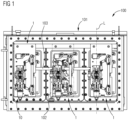
- Figure 1 illustrates a cross section side view of an embodiment of a transformer load tap changer 100 for setting a gear ratio comprising a tank 101 that encloses a fluid, and three power diverter switches arranged inside the tank 101 and immersed in the fluid.
- the transformer load tap changer 100 comprises drive motor drive shaft 102 and insulation shafts 103 to control the power diverter switches and their vacuum interrupter modules 1.
- a movement to operate the transformer load tap changer 100 is received through the motor drive shaft 102. That motor drive shaft 102 is connected to a motor drive unit, which is mounted to the tank 101.
- the motor drive shaft 102 is then connected to a bevel gear structure, which by the means of the insulation shafts 103 is distributing the movement to the three phases of the corresponding vacuum interrupter modules 1.
- FIG. 2 illustrates one power diverter switch assembly or vacuum interrupter module 1 of the transformer load tap changer 100 in a perspective view.
- the vacuum interrupter module 1 comprises an insulation plate 3 and current transformer 2 attached to the insulation plate 3.
- the insulation plate forms a support structure for the vacuum interrupter module 1 and may be composed of a rigid dielectric material, such as fiber-reinforced dielectric plastic.
- On a front side of the insulation plate 3 a bypass switch assembly and a vacuum interrupter assembly 10 is mounted.
- a back-side of the insulation plate 3 can be used for carrying copper bars used for schematic connection.
- Incoming motion from a selector is transferred to a cam end of a control cam 13 through the means of the insulation shafts 103.
- the control cam 13 is configured to actuate the bypass contacts 4 through corresponding bypass levers 5.
- the control cam 13 is configured to load and discharge a spring accumulator inside a driving mechanism 12.
- the vacuum interrupter module 1 comprises the vacuum interrupter assembly 10 including a vacuum interrupter 11 and the driving mechanism 12 that is coupled with the vacuum interrupter 11 and that is configured to drive opening and closing of electrical contacts of the vacuum interrupter 11.
- the transformer load tap changer 100 and the respective vacuum modules 1 may further include for each phase winding, a selector switch assembly and a bypass switch module.
- the selector switch assembly can be configured to make connections between taps, while the bypass switch module may be configured to connect the tap to a main power source.
- the vacuum interrupter module 1 safely carries the current between the tap and a main power circuit.
- a drive system is configured to move a selector switch, the bypass switch module and the vacuum interrupter module 1.
- the control cam 13 is coupled with the vacuum interrupter assembly 10 and is configured to drive the driving mechanism 12 to open and close the electrical contacts of the vacuum interrupter 11 (see Fig. 3 ).
- the driving mechanism 12 includes a driving rod 19 and a guiding tube 18 enclosing the driving rod 19 such that the driving rod 19 is axially movable inside the guiding tube 18 along a longitudinal axis L of the vacuum interrupter assembly 10.
- the respective vacuum interrupter assembly 10 further comprises a damping unit 20 coupled with the driving mechanism 12 and comprising a first chamber 21, a second chamber 22 and a piston 29 arranged there between with respect to the longitudinal axis L (see Figs. 4 and 5 ).
- the chambers 21, 22 are coupled with each other hydraulically and limited by the guiding tube 18, the piston 29 and a first disc 25 and a second disc 26 all arranged axially with respect to the longitudinal axis inside the guiding tube 18.
- the piston 29 is coupled with the driving rod 19 axially movable along the longitudinal axis L such that in interaction with the fluid the damping unit 20 provides hydraulic damping both when opening and when closing the electrical contacts of the vacuum interrupter 11 due to movement of the driving rod 19 and the piston 29 along the longitudinal axis L.
- the vacuum interrupter module 1 further comprises one or more driving springs 14, a locking mechanism 15, an adjusting system 16 and a locking system 17.
- the driving springs 14 accumulate the needed energy to provide proper switching speed of the vacuum interrupter module 1.
- the locking mechanism 15 and the locking system 17 are used for defining the two positions of the vacuum interrupter 11. Further, the locking system 17 is clamping the vacuum interrupter 11 toward the insulation plate 3.
- the adjusting system 16 is configured to adjust a contact gap and to provide solution for axial discrepancies during assembling of the vacuum interrupter module 1 and the vacuum interrupter assembly 10.
- the damping unit 20 is configured to provide reliable damping when the driving rod 19 is closing the vacuum interrupter 11 and when the driving rod 19 is opening the vacuum interrupter 11.
- the figures 4 and 5 each shows an enlarged perspective view of the damping unit 20 of the corresponding vacuum interrupter assembly 10 as circled in dashed lines in figure 3 .
- the damping unit 20 is configured such that it provides more damping when closing the electrical contacts of the vacuum interrupter 11 than when opening the same. Such a higher hydraulic damping force is achieved by the two different chambers 21, 22 and the discs 25, 26 comprising different orifices 27 and 28, respectively.
- the discs 25, 26 and the piston 29 realizes washers or bushings including a respective central opening the driving rod 19 is extending through.
- the discs 25 and 26 are fixedly connected to an inside surface of the guiding tube 18 whereas the piston 29 is fixedly connected to an outside surface of the driving rod 19.
- the inner surface of the guiding tube 18 and/or the outer surface of the driving rod 19 can comprise edges, protrusions and/or grooves to enable precise and stable arrangement of the discs 25, 26 and the piston 29, respectively.
- the first disc 23 comprises two orifices 27 and the second disc 24 comprises two orifices 28 each defining a fluid passage out and into the first chamber 21 and the second chamber 22.
- the orifices 27 and 28 of the first and the second disc 25 and 26 all are circularly limited and a respective diameter of the orifices 27 of the first disc 25 is smaller than a respective diameter of the orifice 28 of the second disc 26.
- the first disc 25 is arranged closer to the vacuum interrupter 11 than the second disc 26.
- the discs 25 and 26 are arranged inside the guiding tube 18 at opposite sides of the piston 29 with respect to the longitudinal axis L.
- the vacuum interrupter assembly 10 is configured such that when the piston 29 is driven towards the first disc 25 the electrical contacts of the vacuum interrupter are closed. Consequently, the vacuum interrupter assembly 10 is configured such that when the piston 29 is driven towards the second disc 26 the electrical contacts of the vacuum interrupter are opened.
- first disc 25 and its orifices 27 are configured to provide a predetermined hydraulic damping when closing the electrical contacts of the vacuum interrupter 11.
- second disc 26 and its orifices 28 are configured to provide a predetermined hydraulic damping when opening the electrical contacts of the vacuum interrupter 11.
- the guiding tube 18 comprises two recesses penetrating a wall of the guiding tube 18 defining a first channel 23 and a second channel 24 from the inside to the outside of the guiding tube 18.
- the first channel 23 is associated to the first chamber 21 and the second channel 24 is associated to the second chamber 22 such that a fluid passage is defined by the orifices 27 of the first disc 25, the first channel 23, the second channel 24 and the orifices 28 of the second disc 26.
- Due to movement of the driving rod 19 and the piston 29 a volume of one chamber 21, 22 is reduced whereas a volume of the other camber 22, 21 is increased.
- the piston 29 then closes the first channel 23 when closing the electrical contacts of the vacuum interrupter 11 and closes the second channel 24 when opening the electrical contacts of the vacuum interrupter 11.
- a size of the piston 29 as well as a size and a location of the first and the second channel 23, 24 in the wall of the guiding tube 18 are configured in coordination with each other to provide a predetermined hydraulic damping force in interaction with the fluid and a size of the orifices 27 and 28 in the discs 25 and 26.
- a size of the orifices 27 of the first disc 25, a size of the orifices 28 of the second disc 26 and a size of the first and the second channel 23 and 24 are configured in coordination with a viscosity of the fluid inside the tank 101.
- the discs 25 and 26, the piston 29 and the channels 23 and 24 are arranged and sized so that the piston 29 nearly closes both the first channel 23 and the second channel 24 in a middle position between the discs 25, 26 and the volume of the chambers 21 and 22 is roughly the same.
- Such a state might be illustrated in figure 4 .
- the piston 29 may have a thickness of a few millimeters, 8 mm for example, with respect to the longitudinal axis L.
- the thickness of the piston 29 is beneficially adapted to a stroke of the movable electrical contacts of the vacuum interrupter 11, which has a value of 4 mm, for example.
- a movable distance of the piston 29 inside the guiding tube 18 should also be adapted to the aforementioned stroke such that the piston can move reliably.
- a size of the orifices 27 of the first disc 25 and/or a size of the orifices 28 of the second disc 26 are configured to be smaller than a size of the first and/or the second channel 23, 24 on the periphery of the guiding tube 18 to reach a more smooth movement.
- the second channel 24 is closed by the piston 29 and the first channel 23 is predetermined opened in part.
- the piston 29 covers only one channel, i.e. an area of fluid leakage is larger, therefore at this point the speed is higher.
- the piston 29 If the movement the piston 29 is continued to close the electrical contacts it will close the first channel 23 and the second channel 24 then is opened in part, predetermined, to reach a desired braking effect, as an oil flow will be only through the two small orifices 27 of the first disk 25.
- the second channel 24, placed on the periphery of the guiding tube 18 is opened in part, thus preventing any braking effect that would be formed by a vacuum in the second chamber 22 inside the guiding tube 18 when moving the piston 29 towards the second disk 28.
- the sequence is the same but the speed is higher, and the orifices 28 of the second disk 26 are larger than the ones in the first disk 25.
- a respective center of the first and the second channel 23, 24 can have a distance of 5 mm from each other, wherein the first and the second channels 23, 24 may comprise a diameter of 4 mm each.
- the second channel 24 might be covered by the piston 29 such that a fluid-permeable area is reduced to 3 mm left with respect to the 4 mm diameter, for example.
- the first channel 23 might be covered by the piston 29 such that a fluid-permeable area is reduced to the half, viz. 2 mm left with respect to the 4 mm diameter, for example.
- the damping unit 20 is implemented in the guiding tube 18 of the driving mechanism 12 in the power diverter switch.
- the damping unit 20 merely comprises three elements and some adaptions on the guiding tube 18 and the driving rod 19 of the vacuum interrupter assembly 10.
- the exact positions of the holes or channels 23, 24 in the wall of the guiding tube 18 enables to provide an exact moment of the damping force and with default of the diameter of the orifices 27, 28 it is possible to achieve a desired reactance of the fluid - respectively damping force. Due to such a configuration, the damping unit 20 enables to beneficially influence the opening and closing speeds of the vacuum interrupter 11 and reduce unwanted bouncing effects during closing of the vacuum interrupter 11.
- the described vacuum interrupter assembly 10 provides a beneficial robustness and contributes to reduced manufacturability and maintenance criteria. Inter alia, this is achieved due to the specifically configured damping unit 20 which is immersed in a dielectric fluid.
- the electrical contacts of the vacuum interrupter 11 are opened and closed by the means of the driving mechanism 12 and the damping unit 20 is implemented in the driving mechanism 12.
- the damping unit 20 according to the illustrated embodiments is configured to provide more damping force when the driving rod 19 is closing the vacuum interrupter 11 than when the driving rod 19 is opening the vacuum interrupter 11. This can be achieved by the two hydraulic chambers 21, 22 and the discs 25, 26 with different orifices 27, 28.
Landscapes
- Engineering & Computer Science (AREA)
- Power Engineering (AREA)
- Driving Mechanisms And Operating Circuits Of Arc-Extinguishing High-Tension Switches (AREA)
- High-Tension Arc-Extinguishing Switches Without Spraying Means (AREA)
Claims (8)
- Vakuumunterbrecheranordnung (10) für einen Leistungsumschalter, die Folgendes umfasst:- einen Vakuumunterbrecher (11), der dazu ausgestaltet ist, zugehörige elektrische Kontakte in einem Vakuum zu öffnen und zu schließen,- einen Antriebsmechanismus (12), der mit dem Vakuumunterbrecher (11) gekoppelt ist und der dazu ausgestaltet ist, das Öffnen und Schließen der elektrischen Kontakte des Vakuumunterbrechers (11) anzutreiben, wobei der Antriebsmechanismus (12) eine Antriebsstange (19) und ein Führungsrohr (18) umfasst, das die Antriebsstange (19) umschließt, so dass die Antriebsstange (19) innerhalb des Führungsrohrs (18) entlang einer Längsachse (L) der Vakuumunterbrecheranordnung (10) axial beweglich ist,- eine Dämpfungseinheit (20), die mit dem Antriebsmechanismus (12) gekoppelt ist und eine erste Kammer (21), eine zweite Kammer (22) und einen in Bezug auf die Längsachse (L) dazwischen angeordneten Kolben (29) umfasst, wobei die Kammern (21, 22) hydraulisch miteinander gekoppelt und durch das Führungsrohr (18) und den Kolben (29) begrenzt sind, und wobei der Kolben (29) mit der Antriebsstange (19) entlang der Längsachse (L) axial beweglich gekoppelt ist, so dass die Dämpfungseinheit (20) in Wechselwirkung mit einem Fluid sowohl beim Öffnen als auch beim Schließen der elektrischen Kontakte des Vakuumunterbrechers (11) aufgrund einer Bewegung der Antriebsstange (19) und des Kolbens (29) eine hydraulische Dämpfung bereitstellt, dadurch gekennzeichnet, dass die Dämpfungseinheit (20) ferner umfasst:
eine erste Scheibe (23) und eine zweite Scheibe (24), die fest an dem Führungsrohr (18) an in Bezug auf die Längsachse (L) gegenüberliegenden Seiten des Kolbens (29) angeordnet sind, die die erste bzw. die zweite Kammer (21, 22) begrenzen, wobei die erste Scheibe (23), die zweite Scheibe (24) und der Kolben (29) alle axial in Bezug auf die Längsachse (L) innerhalb des Führungsrohres (18) angeordnet sind und die Antriebsstange (19) umschließen, so dass die erste Scheibe (23) und die zweite Scheibe (24) mit dem Führungsrohr (18) verbunden sind und der Kolben (29) mit der Antriebsstange (19) verbunden ist und alle radial zwischen dem Führungsrohr (18) und der Antriebsstange (19) angeordnet sind. - Vakuumunterbrecheranordnung (10) nach Anspruch 1, wobei die erste Scheibe (23) mindestens eine Öffnung (27) umfasst und die zweite Scheibe (24) mindestens eine Öffnung (28) umfasst, die jeweils einen Fluiddurchgang aus und in die erste Kammer (21) und die zweite Kammer (22) definieren.
- Vakuumunterbrecheranordnung (10) nach Anspruch 2, wobei die mindestens eine Öffnung (27)
der ersten Scheibe (25) und die mindestens eine Öffnung (28) der zweiten Scheibe (26) beide kreisförmig begrenzt sind und ein Durchmesser der Öffnung (27) der ersten Scheibe (25) kleiner als ein Durchmesser der Öffnung (28) der zweiten Scheibe (26) ist, und wobei die erste Scheibe (25) dazu ausgestaltet ist, beim Schließen der elektrischen Kontakte des Vakuumunterbrechers (11) eine hydraulische Dämpfung bereitzustellen. - Vakuumunterbrecheranordnung (10) nach einem der Ansprüche 2 oder 3, wobei das Führungsrohr (18) zwei eine Wand des Führungsrohrs (18) durchdringende Aussparungen umfasst, die einen ersten Kanal (23) und einen zweiten Kanal (24) definieren, die der ersten Kammer (21) bzw. der zweiten Kammer (22) zugeordnet sind, so dass ein Fluiddurchgang durch die Öffnung (27) der ersten Scheibe (25), den ersten Kanal (23), den zweiten Kanal (24) und die Öffnung (28) der zweiten Scheibe (26) definiert ist, wobei der Kolben (29) mit der Antriebsstange (19) verbunden ist, so dass er aufgrund einer Bewegung der Antriebsstange (19) beim Schließen der elektrischen Kontakte des Vakuumunterbrechers (11) den ersten Kanal (23) verschließt und beim Öffnen der elektrischen Kontakte des Vakuumunterbrechers (11) den zweiten Kanal (24) verschließt.
- Vakuumunterbrecheranordnung (10) nach Anspruch 4, wobei eine Größe des Kolbens (29) und/oder eine Größe und/oder eine Position des ersten und des zweiten Kanals (23, 24) in der Wand des Führungsrohres (18) in Abstimmung miteinander ausgestaltet sind, um eine vorbestimmte hydraulische Dämpfungskraft in Wechselwirkung mit einem Fluid bereitzustellen, das in Bezug auf einen Betriebszustand der Vakuumunterbrecheranordnung (10) innerhalb und außerhalb des Führungsrohrs (18) strömen soll.
- Vakuumunterbrecheranordnung (10) nach einem der vorhergehenden Ansprüche in Verbindung mit Anspruch 2, wobei die Öffnung (27) der ersten Scheibe (25), die Öffnung (28) der zweiten Scheibe (26), der erste Kanal (23) und/oder der zweite Kanal (24) eine jeweilige Größe umfassen, die in Abstimmung mit einer Viskosität eines Fluids ausgestaltet ist, das innerhalb und außerhalb des Führungsrohrs (18) strömen soll, um in Bezug auf einen Betriebszustand der Vakuumunterbrecheranordnung (10) in Wechselwirkung mit dem Fluid eine vorbestimmte hydraulische Dämpfungskraft bereitzustellen.
- Leistungsumschalter für einen Transformatorlaststufenschalter (100), der Folgendes umfasst:- eine Isolationsplatte (3),- einen Steuernocken (13), und- eine Vakuumunterbrecheranordnung (10) nach einem der vorhergehenden Ansprüche, die sowohl mit der Isolationsplatte (3) als auch mit dem Steuernocken (13) gekoppelt ist, wobei der Steuernocken (13) dazu ausgestaltet ist, den Antriebsmechanismus (12) der Vakuumunterbrecheranordnung (10) anzutreiben, um die elektrischen Kontakte des Vakuumunterbrechers (11) zu öffnen und zu schließen.
- Transformatorlaststufenschalter (100) zum Einstellen eines Übersetzungsverhältnisses, umfassend:- einen Tank (101), der ein Fluid umschließt, und- mindestens einen Leistungsumschalter nach Anspruch 7, der innerhalb des Tanks (101) angeordnet und in das Fluid eingetaucht ist.
Priority Applications (6)
| Application Number | Priority Date | Filing Date | Title |
|---|---|---|---|
| EP21170940.7A EP4084032B1 (de) | 2021-04-28 | 2021-04-28 | Vakuumschalteranordnung für einen leistungsumschalter, leistungsumschalter für einen transformatorlaststufenschalter und transformatorlaststufenschalter |
| EP21176871.8A EP4084033B1 (de) | 2021-04-28 | 2021-05-31 | Vakuumschaltröhrenmodul für einen stufenschalter, leistungsumleitungsschalter und stufenschalter |
| KR1020237017412A KR102655004B1 (ko) | 2021-04-28 | 2022-02-03 | 전력 변환기 스위치를 위한 진공 차단기 조립체, 변압기 부하 탭 절환기를 위한 전력 변환기 스위치 및 변압기 부하 탭 절환기 |
| PCT/EP2022/052583 WO2022228740A1 (en) | 2021-04-28 | 2022-02-03 | Vacuum interrupter assembly for a power diverter switch, power diverter switch for a transformer load tap changer and transformer load tap changer |
| CN202280007450.6A CN116670794B (zh) | 2021-04-28 | 2022-02-03 | 用于功率转换开关的真空断续器组件、用于变压器负载抽头变换器的功率转换开关和变压器负载抽头变换器 |
| US17/669,557 US12131879B2 (en) | 2021-04-28 | 2022-02-11 | Vacuum interrupter module for a tap changer, power diverter switch, and tap changer |
Applications Claiming Priority (1)
| Application Number | Priority Date | Filing Date | Title |
|---|---|---|---|
| EP21170940.7A EP4084032B1 (de) | 2021-04-28 | 2021-04-28 | Vakuumschalteranordnung für einen leistungsumschalter, leistungsumschalter für einen transformatorlaststufenschalter und transformatorlaststufenschalter |
Publications (2)
| Publication Number | Publication Date |
|---|---|
| EP4084032A1 EP4084032A1 (de) | 2022-11-02 |
| EP4084032B1 true EP4084032B1 (de) | 2025-06-04 |
Family
ID=75728711
Family Applications (2)
| Application Number | Title | Priority Date | Filing Date |
|---|---|---|---|
| EP21170940.7A Active EP4084032B1 (de) | 2021-04-28 | 2021-04-28 | Vakuumschalteranordnung für einen leistungsumschalter, leistungsumschalter für einen transformatorlaststufenschalter und transformatorlaststufenschalter |
| EP21176871.8A Active EP4084033B1 (de) | 2021-04-28 | 2021-05-31 | Vakuumschaltröhrenmodul für einen stufenschalter, leistungsumleitungsschalter und stufenschalter |
Family Applications After (1)
| Application Number | Title | Priority Date | Filing Date |
|---|---|---|---|
| EP21176871.8A Active EP4084033B1 (de) | 2021-04-28 | 2021-05-31 | Vakuumschaltröhrenmodul für einen stufenschalter, leistungsumleitungsschalter und stufenschalter |
Country Status (5)
| Country | Link |
|---|---|
| US (1) | US12131879B2 (de) |
| EP (2) | EP4084032B1 (de) |
| KR (1) | KR102655004B1 (de) |
| CN (1) | CN116670794B (de) |
| WO (1) | WO2022228740A1 (de) |
Families Citing this family (2)
| Publication number | Priority date | Publication date | Assignee | Title |
|---|---|---|---|---|
| WO2025045329A1 (en) * | 2023-08-25 | 2025-03-06 | Hitachi Energy Ltd | Vacuum interrupter assembly for a power diverter switch, power diverter switch for a transformer load tap changer and transformer load tap changer |
| CN118866600B (zh) * | 2024-09-29 | 2025-04-29 | 帝森克罗德集团有限公司 | 一种节能型高压真空断路器 |
Family Cites Families (44)
| Publication number | Priority date | Publication date | Assignee | Title |
|---|---|---|---|---|
| CA658038A (en) | 1963-02-19 | Wagner Electric Corporation | Tap changing apparatus | |
| DE639163C (de) | 1933-07-02 | 1936-11-30 | Siemens Schuckertwerke Akt Ges | Regelschalter mit Getriebe fuer Stufentransformatoren |
| US2785242A (en) | 1955-06-13 | 1957-03-12 | Westinghouse Electric Corp | Tap-changers |
| US2891405A (en) | 1956-10-02 | 1959-06-23 | Mallory & Co Inc P R | Intermittent drive mechanism |
| DE1170260B (de) * | 1958-06-10 | 1964-05-14 | Boge Gmbh | Hydraulischer Zweirohr-Teleskopdaempfer, insbesondere fuer Kraftfahrzeuge |
| US3066208A (en) | 1958-12-08 | 1962-11-27 | Wagner Electric Corp | Tap changing apparatus |
| US3155782A (en) | 1959-05-01 | 1964-11-03 | Mc Graw Edison Co | Switch actuating mechanism for controlled speed tap changer |
| US3045090A (en) | 1959-05-08 | 1962-07-17 | Mc Graw Edison Co | Tap changer movable contact |
| US3204176A (en) | 1961-04-26 | 1965-08-31 | Mc Graw Edison Co | Tap changing furnace transformer |
| CH428928A (de) * | 1965-11-02 | 1967-01-31 | Bbc Brown Boveri & Cie | Einrichtung an einem Lastumschalter eines Stufenschalters für Regeltransformatoren |
| US3436646A (en) | 1966-08-02 | 1969-04-01 | Westinghouse Electric Corp | Load tap changer systems including protective apparatus for monitoring the operation of the transfer switches |
| US3472981A (en) | 1966-08-05 | 1969-10-14 | Gen Electric | Pressure responsive protective means for vacuum type circuit interrupters immersed in liquid |
| US3532842A (en) | 1966-08-05 | 1970-10-06 | Gen Electric | Switch actuating and control mechanism for vacuum type electric circuit interrupters with lost-motion and bellows biasing means |
| US3720867A (en) * | 1972-02-04 | 1973-03-13 | Gen Electric | Fail safe vacuum type circuit interrupter and associated load current tap changer for electric induction apparatus |
| US5191179A (en) * | 1989-11-09 | 1993-03-02 | Cooper Power Systems, Inc. | Tap selector anti-arcing system |
| DE4009038A1 (de) | 1990-03-21 | 1991-09-26 | Reinhausen Maschf Scheubeck | Verfahren und anordnung fuer ein ueberwachungssystem fuer stufenschalter von stufentransformatoren |
| DE4009503A1 (de) | 1990-03-24 | 1991-09-26 | Reinhausen Maschf Scheubeck | Schrittschaltgetriebe fuer stufenwaehler von stufentransformatoren |
| DE4011019C1 (de) * | 1990-04-05 | 1991-12-05 | Maschinenfabrik Reinhausen Gmbh, 8400 Regensburg, De | |
| DE4034126C1 (de) | 1990-10-26 | 1992-03-05 | Maschinenfabrik Reinhausen Gmbh, 8400 Regensburg, De | |
| DE4126824C1 (de) | 1991-08-14 | 1993-04-08 | Maschinenfabrik Reinhausen Gmbh, 8400 Regensburg, De | |
| US5594223A (en) * | 1993-12-07 | 1997-01-14 | Fuji Electric Co., Ltd. | Vacuum switch bulb type change over switch for on-load tap changer |
| US5589675A (en) * | 1994-04-08 | 1996-12-31 | Trinetics, Inc. | Vacuum switch |
| DE19743864C1 (de) | 1997-10-04 | 1999-04-15 | Reinhausen Maschf Scheubeck | Stufenschalter |
| DE19743865C1 (de) | 1997-10-04 | 1999-04-15 | Reinhausen Maschf Scheubeck | Stufenschalter |
| US6693247B1 (en) | 2000-06-09 | 2004-02-17 | Mcgraw-Edison Company | Load tap changer with direct drive and brake |
| US8430136B2 (en) | 2011-03-03 | 2013-04-30 | Abb Technology Ag | Oil catch tray for load tap changer tank |
| WO2012134958A1 (en) * | 2011-03-25 | 2012-10-04 | Abb Technology Ag | An improved tap changer |
| EP2689441B1 (de) | 2011-03-25 | 2015-01-07 | ABB Technology AG | Stufenschalter mit einem verbesserten aufbau |
| WO2012134805A1 (en) | 2011-03-25 | 2012-10-04 | Abb Technology Ag | Selector switch assembly for load tap changer |
| BR112013024622B1 (pt) | 2011-03-25 | 2020-11-10 | Abb Schweiz Ag | trocador de tomada de carga |
| CN103548106B (zh) | 2011-03-25 | 2017-02-08 | Abb技术有限公司 | 具有改进的真空断续器致动组件的分接头变换器 |
| CN103548107B (zh) | 2011-03-27 | 2016-08-24 | Abb技术有限公司 | 具有改进的监视系统的抽头变换器 |
| BR112013024908B1 (pt) | 2011-03-27 | 2021-02-17 | Abb Schweiz Ag | comutador de derivação em carga para comutar derivações em um enrolamento de um transformador |
| US9275782B2 (en) * | 2011-08-17 | 2016-03-01 | Hubbell Incorporated | Dual stroke mechanically latched mechanism |
| DE102011113718A1 (de) * | 2011-09-17 | 2013-03-21 | Maschinenfabrik Reinhausen Gmbh | Laststufenschalter |
| DE102012202327B4 (de) * | 2012-02-16 | 2015-01-08 | Maschinenfabrik Reinhausen Gmbh | Laststufenschalter mit mindestens zwei Vakuumschaltröhren und Antrieb für einen Lastumschalter mit mindestens zwei Vakuumschaltröhren |
| CN102709106B (zh) * | 2012-05-17 | 2015-03-11 | 上海华明电力设备集团有限公司 | 真空灭弧转换选择器 |
| DE102012105152B4 (de) * | 2012-06-14 | 2015-11-12 | Maschinenfabrik Reinhausen Gmbh | Laststufenschalter zur unterbrechungslosen Umschaltung zwischen verschiedenen Wicklungsanzapfungen eines Stufentransformators |
| DE102013102299B4 (de) * | 2013-03-08 | 2014-12-04 | Maschinenfabrik Reinhausen Gmbh | Linearwähler |
| DE102014112764A1 (de) * | 2014-09-04 | 2016-03-10 | Maschinenfabrik Reinhausen Gmbh | Schaltanordnung für einen Regeltransformator, insbesondere Polungsschalter |
| DE102014112763A1 (de) * | 2014-09-04 | 2016-03-10 | Maschinenfabrik Reinhausen Gmbh | Schaltanordnung für einen Regeltransformator, insbesondere Vorwähler |
| PT3086343T (pt) * | 2015-04-21 | 2019-03-14 | Ormazabal Corporate Tech A I E | Dispositivo comutador de derivação sob carga |
| DE102016104499B3 (de) * | 2016-03-11 | 2017-04-27 | Maschinenfabrik Reinhausen Gmbh | Wähler für einen Laststufenschalter und Laststufenschalter mit Lastumschalter und Wähler |
| CN109559933A (zh) * | 2018-11-16 | 2019-04-02 | 吴长兰 | 中高压开关装置 |
-
2021
- 2021-04-28 EP EP21170940.7A patent/EP4084032B1/de active Active
- 2021-05-31 EP EP21176871.8A patent/EP4084033B1/de active Active
-
2022
- 2022-02-03 CN CN202280007450.6A patent/CN116670794B/zh active Active
- 2022-02-03 WO PCT/EP2022/052583 patent/WO2022228740A1/en not_active Ceased
- 2022-02-03 KR KR1020237017412A patent/KR102655004B1/ko active Active
- 2022-02-11 US US17/669,557 patent/US12131879B2/en active Active
Also Published As
| Publication number | Publication date |
|---|---|
| US20220384123A1 (en) | 2022-12-01 |
| KR20230084311A (ko) | 2023-06-12 |
| CN116670794A (zh) | 2023-08-29 |
| WO2022228740A1 (en) | 2022-11-03 |
| EP4084033A1 (de) | 2022-11-02 |
| CN116670794B (zh) | 2025-02-18 |
| KR102655004B1 (ko) | 2024-04-05 |
| US12131879B2 (en) | 2024-10-29 |
| EP4084032A1 (de) | 2022-11-02 |
| EP4084033B1 (de) | 2025-05-07 |
Similar Documents
| Publication | Publication Date | Title |
|---|---|---|
| KR102446586B1 (ko) | 부하시 탭 절환기 | |
| EP4084032B1 (de) | Vakuumschalteranordnung für einen leistungsumschalter, leistungsumschalter für einen transformatorlaststufenschalter und transformatorlaststufenschalter | |
| EP3104387B1 (de) | Wahlschalteranordnung für laststufenschalter | |
| US9640341B2 (en) | On-load tap changer | |
| KR102642659B1 (ko) | 부하시 탭 절환기용 스위칭 시스템, 부하시 탭 절환기 및 부하시 탭 절환기의 탭 연결을 스위칭하는 방법 | |
| US10102990B2 (en) | On-load tap changer | |
| US20150008104A1 (en) | On-load tap changer with two vacuum interrupters and drive therefor | |
| EP1108261A1 (de) | Betriebsteuerungsvorrichtung für hoch oder mittelspannungschaltgerät | |
| KR102638367B1 (ko) | 전력 다이버터 스위치용 진공 차단기를 제어하기 위한 시스템, 전력 다이버터 스위치 및 온로드 탭 전환기 | |
| EP3155627B1 (de) | Schaltergesteuerte resistorschaltanordnung | |
| KR102777220B1 (ko) | 온-부하 탭 절환기용 부하 전달 스위치, 및 온-부하 탭 절환기 | |
| EA030580B1 (ru) | Коммутационный аппарат для электроэнергетических систем | |
| EP2546847B1 (de) | Schneller Switch mit Thomson-Spule und -Dämpfung | |
| EP4208884B1 (de) | Schaltsystem für einen laststufenschalter, laststufenschalter und verfahren zum schalten einer stufenverbindung eines laststufenschalters | |
| WO2025045329A1 (en) | Vacuum interrupter assembly for a power diverter switch, power diverter switch for a transformer load tap changer and transformer load tap changer | |
| US20040061504A1 (en) | Vacuum circuit-breaker and a method for controlling the same | |
| EP4654236A1 (de) | Bypasskontaktsystem, vakuumschaltermodul und stufenschalter | |
| GB2593932A (en) | Commutating electric circuit breaker with reliable actuating mechanism and operation method thereto | |
| KR102835654B1 (ko) | 전력 다이버터 스위치용 진공 단속기를 제어하기 위한 시스템, 전력 다이버터 스위치 및 온로드 탭 전환기 | |
| JP3900510B2 (ja) | 負荷時タップ切換器 | |
| JP2022543875A (ja) | 直列接続された2つの断路器ユニットを備えた開閉装置 | |
| CN111354580A (zh) | 用于中压断路器的致动器 | |
| HK1228565A1 (en) | Load selector | |
| HK1228565B (en) | Load selector |
Legal Events
| Date | Code | Title | Description |
|---|---|---|---|
| PUAI | Public reference made under article 153(3) epc to a published international application that has entered the european phase |
Free format text: ORIGINAL CODE: 0009012 |
|
| STAA | Information on the status of an ep patent application or granted ep patent |
Free format text: STATUS: THE APPLICATION HAS BEEN PUBLISHED |
|
| AK | Designated contracting states |
Kind code of ref document: A1 Designated state(s): AL AT BE BG CH CY CZ DE DK EE ES FI FR GB GR HR HU IE IS IT LI LT LU LV MC MK MT NL NO PL PT RO RS SE SI SK SM TR |
|
| STAA | Information on the status of an ep patent application or granted ep patent |
Free format text: STATUS: REQUEST FOR EXAMINATION WAS MADE |
|
| 17P | Request for examination filed |
Effective date: 20230428 |
|
| RBV | Designated contracting states (corrected) |
Designated state(s): AL AT BE BG CH CY CZ DE DK EE ES FI FR GB GR HR HU IE IS IT LI LT LU LV MC MK MT NL NO PL PT RO RS SE SI SK SM TR |
|
| P01 | Opt-out of the competence of the unified patent court (upc) registered |
Effective date: 20230527 |
|
| RAP1 | Party data changed (applicant data changed or rights of an application transferred) |
Owner name: HITACHI ENERGY LTD |
|
| REG | Reference to a national code |
Ref legal event code: R079 Free format text: PREVIOUS MAIN CLASS: H01H0001500000 Ref country code: DE Ref legal event code: R079 Ref document number: 602021031619 Country of ref document: DE Free format text: PREVIOUS MAIN CLASS: H01H0001500000 Ipc: H01H0009000000 |
|
| GRAP | Despatch of communication of intention to grant a patent |
Free format text: ORIGINAL CODE: EPIDOSNIGR1 |
|
| STAA | Information on the status of an ep patent application or granted ep patent |
Free format text: STATUS: GRANT OF PATENT IS INTENDED |
|
| RIC1 | Information provided on ipc code assigned before grant |
Ipc: H01H 33/666 20060101ALN20241119BHEP Ipc: H01H 3/42 20060101ALI20241119BHEP Ipc: H01F 29/04 20060101ALI20241119BHEP Ipc: H01H 9/00 20060101AFI20241119BHEP |
|
| INTG | Intention to grant announced |
Effective date: 20241205 |
|
| GRAS | Grant fee paid |
Free format text: ORIGINAL CODE: EPIDOSNIGR3 |
|
| GRAA | (expected) grant |
Free format text: ORIGINAL CODE: 0009210 |
|
| STAA | Information on the status of an ep patent application or granted ep patent |
Free format text: STATUS: THE PATENT HAS BEEN GRANTED |
|
| AK | Designated contracting states |
Kind code of ref document: B1 Designated state(s): AL AT BE BG CH CY CZ DE DK EE ES FI FR GB GR HR HU IE IS IT LI LT LU LV MC MK MT NL NO PL PT RO RS SE SI SK SM TR |
|
| REG | Reference to a national code |
Ref country code: GB Ref legal event code: FG4D |
|
| REG | Reference to a national code |
Ref country code: CH Ref legal event code: EP |
|
| REG | Reference to a national code |
Ref country code: DE Ref legal event code: R096 Ref document number: 602021031619 Country of ref document: DE |
|
| REG | Reference to a national code |
Ref country code: IE Ref legal event code: FG4D |
|
| REG | Reference to a national code |
Ref country code: NL Ref legal event code: MP Effective date: 20250604 |
|
| PG25 | Lapsed in a contracting state [announced via postgrant information from national office to epo] |
Ref country code: ES Free format text: LAPSE BECAUSE OF FAILURE TO SUBMIT A TRANSLATION OF THE DESCRIPTION OR TO PAY THE FEE WITHIN THE PRESCRIBED TIME-LIMIT Effective date: 20250604 Ref country code: FI Free format text: LAPSE BECAUSE OF FAILURE TO SUBMIT A TRANSLATION OF THE DESCRIPTION OR TO PAY THE FEE WITHIN THE PRESCRIBED TIME-LIMIT Effective date: 20250604 |
|
| REG | Reference to a national code |
Ref country code: LT Ref legal event code: MG9D |
|
| PG25 | Lapsed in a contracting state [announced via postgrant information from national office to epo] |
Ref country code: NO Free format text: LAPSE BECAUSE OF FAILURE TO SUBMIT A TRANSLATION OF THE DESCRIPTION OR TO PAY THE FEE WITHIN THE PRESCRIBED TIME-LIMIT Effective date: 20250904 Ref country code: GR Free format text: LAPSE BECAUSE OF FAILURE TO SUBMIT A TRANSLATION OF THE DESCRIPTION OR TO PAY THE FEE WITHIN THE PRESCRIBED TIME-LIMIT Effective date: 20250905 |
|
| PG25 | Lapsed in a contracting state [announced via postgrant information from national office to epo] |
Ref country code: PL Free format text: LAPSE BECAUSE OF FAILURE TO SUBMIT A TRANSLATION OF THE DESCRIPTION OR TO PAY THE FEE WITHIN THE PRESCRIBED TIME-LIMIT Effective date: 20250604 |
|
| PG25 | Lapsed in a contracting state [announced via postgrant information from national office to epo] |
Ref country code: HR Free format text: LAPSE BECAUSE OF FAILURE TO SUBMIT A TRANSLATION OF THE DESCRIPTION OR TO PAY THE FEE WITHIN THE PRESCRIBED TIME-LIMIT Effective date: 20250604 |
|
| PG25 | Lapsed in a contracting state [announced via postgrant information from national office to epo] |
Ref country code: RS Free format text: LAPSE BECAUSE OF FAILURE TO SUBMIT A TRANSLATION OF THE DESCRIPTION OR TO PAY THE FEE WITHIN THE PRESCRIBED TIME-LIMIT Effective date: 20250904 |
|
| PG25 | Lapsed in a contracting state [announced via postgrant information from national office to epo] |
Ref country code: LV Free format text: LAPSE BECAUSE OF FAILURE TO SUBMIT A TRANSLATION OF THE DESCRIPTION OR TO PAY THE FEE WITHIN THE PRESCRIBED TIME-LIMIT Effective date: 20250604 |
|
| PG25 | Lapsed in a contracting state [announced via postgrant information from national office to epo] |
Ref country code: NL Free format text: LAPSE BECAUSE OF FAILURE TO SUBMIT A TRANSLATION OF THE DESCRIPTION OR TO PAY THE FEE WITHIN THE PRESCRIBED TIME-LIMIT Effective date: 20250604 |
|
| PG25 | Lapsed in a contracting state [announced via postgrant information from national office to epo] |
Ref country code: PT Free format text: LAPSE BECAUSE OF FAILURE TO SUBMIT A TRANSLATION OF THE DESCRIPTION OR TO PAY THE FEE WITHIN THE PRESCRIBED TIME-LIMIT Effective date: 20251006 |
|
| REG | Reference to a national code |
Ref country code: AT Ref legal event code: MK05 Ref document number: 1801223 Country of ref document: AT Kind code of ref document: T Effective date: 20250604 |
|
| PG25 | Lapsed in a contracting state [announced via postgrant information from national office to epo] |
Ref country code: IS Free format text: LAPSE BECAUSE OF FAILURE TO SUBMIT A TRANSLATION OF THE DESCRIPTION OR TO PAY THE FEE WITHIN THE PRESCRIBED TIME-LIMIT Effective date: 20251004 |
|
| PG25 | Lapsed in a contracting state [announced via postgrant information from national office to epo] |
Ref country code: SM Free format text: LAPSE BECAUSE OF FAILURE TO SUBMIT A TRANSLATION OF THE DESCRIPTION OR TO PAY THE FEE WITHIN THE PRESCRIBED TIME-LIMIT Effective date: 20250604 Ref country code: AT Free format text: LAPSE BECAUSE OF FAILURE TO SUBMIT A TRANSLATION OF THE DESCRIPTION OR TO PAY THE FEE WITHIN THE PRESCRIBED TIME-LIMIT Effective date: 20250604 |
|
| PG25 | Lapsed in a contracting state [announced via postgrant information from national office to epo] |
Ref country code: CZ Free format text: LAPSE BECAUSE OF FAILURE TO SUBMIT A TRANSLATION OF THE DESCRIPTION OR TO PAY THE FEE WITHIN THE PRESCRIBED TIME-LIMIT Effective date: 20250604 |
|
| PG25 | Lapsed in a contracting state [announced via postgrant information from national office to epo] |
Ref country code: EE Free format text: LAPSE BECAUSE OF FAILURE TO SUBMIT A TRANSLATION OF THE DESCRIPTION OR TO PAY THE FEE WITHIN THE PRESCRIBED TIME-LIMIT Effective date: 20250604 |
|
| PG25 | Lapsed in a contracting state [announced via postgrant information from national office to epo] |
Ref country code: SK Free format text: LAPSE BECAUSE OF FAILURE TO SUBMIT A TRANSLATION OF THE DESCRIPTION OR TO PAY THE FEE WITHIN THE PRESCRIBED TIME-LIMIT Effective date: 20250604 |
|
| PG25 | Lapsed in a contracting state [announced via postgrant information from national office to epo] |
Ref country code: IT Free format text: LAPSE BECAUSE OF FAILURE TO SUBMIT A TRANSLATION OF THE DESCRIPTION OR TO PAY THE FEE WITHIN THE PRESCRIBED TIME-LIMIT Effective date: 20250604 |
|
| REG | Reference to a national code |
Ref country code: DE Ref legal event code: R097 Ref document number: 602021031619 Country of ref document: DE |
|
| PLBE | No opposition filed within time limit |
Free format text: ORIGINAL CODE: 0009261 |
|
| STAA | Information on the status of an ep patent application or granted ep patent |
Free format text: STATUS: NO OPPOSITION FILED WITHIN TIME LIMIT |
|
| PG25 | Lapsed in a contracting state [announced via postgrant information from national office to epo] |
Ref country code: DK Free format text: LAPSE BECAUSE OF FAILURE TO SUBMIT A TRANSLATION OF THE DESCRIPTION OR TO PAY THE FEE WITHIN THE PRESCRIBED TIME-LIMIT Effective date: 20250604 |
|
| REG | Reference to a national code |
Ref country code: CH Ref legal event code: L10 Free format text: ST27 STATUS EVENT CODE: U-0-0-L10-L00 (AS PROVIDED BY THE NATIONAL OFFICE) Effective date: 20260416 |