EP4084189A1 - Traktionsbatterie eines kraftfahrzeuges - Google Patents
Traktionsbatterie eines kraftfahrzeuges Download PDFInfo
- Publication number
- EP4084189A1 EP4084189A1 EP22020037.2A EP22020037A EP4084189A1 EP 4084189 A1 EP4084189 A1 EP 4084189A1 EP 22020037 A EP22020037 A EP 22020037A EP 4084189 A1 EP4084189 A1 EP 4084189A1
- Authority
- EP
- European Patent Office
- Prior art keywords
- busbar
- battery
- housing
- traction battery
- module
- Prior art date
- Legal status (The legal status is an assumption and is not a legal conclusion. Google has not performed a legal analysis and makes no representation as to the accuracy of the status listed.)
- Granted
Links
Images


Classifications
-
- H—ELECTRICITY
- H01—ELECTRIC ELEMENTS
- H01M—PROCESSES OR MEANS, e.g. BATTERIES, FOR THE DIRECT CONVERSION OF CHEMICAL ENERGY INTO ELECTRICAL ENERGY
- H01M50/00—Constructional details or processes of manufacture of the non-active parts of electrochemical cells other than fuel cells, e.g. hybrid cells
- H01M50/50—Current conducting connections for cells or batteries
- H01M50/502—Interconnectors for connecting terminals of adjacent batteries; Interconnectors for connecting cells outside a battery casing
- H01M50/507—Interconnectors for connecting terminals of adjacent batteries; Interconnectors for connecting cells outside a battery casing comprising an arrangement of two or more busbars within a container structure, e.g. busbar modules
-
- B—PERFORMING OPERATIONS; TRANSPORTING
- B60—VEHICLES IN GENERAL
- B60L—PROPULSION OF ELECTRICALLY-PROPELLED VEHICLES; SUPPLYING ELECTRIC POWER FOR AUXILIARY EQUIPMENT OF ELECTRICALLY-PROPELLED VEHICLES; ELECTRODYNAMIC BRAKE SYSTEMS FOR VEHICLES IN GENERAL; MAGNETIC SUSPENSION OR LEVITATION FOR VEHICLES; MONITORING OPERATING VARIABLES OF ELECTRICALLY-PROPELLED VEHICLES; ELECTRIC SAFETY DEVICES FOR ELECTRICALLY-PROPELLED VEHICLES
- B60L50/00—Electric propulsion with power supplied within the vehicle
- B60L50/50—Electric propulsion with power supplied within the vehicle using propulsion power supplied by batteries or fuel cells
- B60L50/60—Electric propulsion with power supplied within the vehicle using propulsion power supplied by batteries or fuel cells using power supplied by batteries
-
- H—ELECTRICITY
- H01—ELECTRIC ELEMENTS
- H01M—PROCESSES OR MEANS, e.g. BATTERIES, FOR THE DIRECT CONVERSION OF CHEMICAL ENERGY INTO ELECTRICAL ENERGY
- H01M10/00—Secondary cells; Manufacture thereof
- H01M10/60—Heating or cooling; Temperature control
- H01M10/61—Types of temperature control
- H01M10/613—Cooling or keeping cold
-
- H—ELECTRICITY
- H01—ELECTRIC ELEMENTS
- H01M—PROCESSES OR MEANS, e.g. BATTERIES, FOR THE DIRECT CONVERSION OF CHEMICAL ENERGY INTO ELECTRICAL ENERGY
- H01M10/00—Secondary cells; Manufacture thereof
- H01M10/60—Heating or cooling; Temperature control
- H01M10/62—Heating or cooling; Temperature control specially adapted for specific applications
- H01M10/625—Vehicles
-
- H—ELECTRICITY
- H01—ELECTRIC ELEMENTS
- H01M—PROCESSES OR MEANS, e.g. BATTERIES, FOR THE DIRECT CONVERSION OF CHEMICAL ENERGY INTO ELECTRICAL ENERGY
- H01M10/00—Secondary cells; Manufacture thereof
- H01M10/60—Heating or cooling; Temperature control
- H01M10/65—Means for temperature control structurally associated with the cells
- H01M10/653—Means for temperature control structurally associated with the cells characterised by electrically insulating or thermally conductive materials
-
- H—ELECTRICITY
- H01—ELECTRIC ELEMENTS
- H01M—PROCESSES OR MEANS, e.g. BATTERIES, FOR THE DIRECT CONVERSION OF CHEMICAL ENERGY INTO ELECTRICAL ENERGY
- H01M10/00—Secondary cells; Manufacture thereof
- H01M10/60—Heating or cooling; Temperature control
- H01M10/65—Means for temperature control structurally associated with the cells
- H01M10/655—Solid structures for heat exchange or heat conduction
- H01M10/6553—Terminals or leads
-
- H—ELECTRICITY
- H01—ELECTRIC ELEMENTS
- H01M—PROCESSES OR MEANS, e.g. BATTERIES, FOR THE DIRECT CONVERSION OF CHEMICAL ENERGY INTO ELECTRICAL ENERGY
- H01M10/00—Secondary cells; Manufacture thereof
- H01M10/60—Heating or cooling; Temperature control
- H01M10/65—Means for temperature control structurally associated with the cells
- H01M10/655—Solid structures for heat exchange or heat conduction
- H01M10/6554—Rods or plates
-
- H—ELECTRICITY
- H01—ELECTRIC ELEMENTS
- H01M—PROCESSES OR MEANS, e.g. BATTERIES, FOR THE DIRECT CONVERSION OF CHEMICAL ENERGY INTO ELECTRICAL ENERGY
- H01M50/00—Constructional details or processes of manufacture of the non-active parts of electrochemical cells other than fuel cells, e.g. hybrid cells
- H01M50/20—Mountings; Secondary casings or frames; Racks, modules or packs; Suspension devices; Shock absorbers; Transport or carrying devices; Holders
- H01M50/204—Racks, modules or packs for multiple batteries or multiple cells
-
- H—ELECTRICITY
- H01—ELECTRIC ELEMENTS
- H01M—PROCESSES OR MEANS, e.g. BATTERIES, FOR THE DIRECT CONVERSION OF CHEMICAL ENERGY INTO ELECTRICAL ENERGY
- H01M50/00—Constructional details or processes of manufacture of the non-active parts of electrochemical cells other than fuel cells, e.g. hybrid cells
- H01M50/20—Mountings; Secondary casings or frames; Racks, modules or packs; Suspension devices; Shock absorbers; Transport or carrying devices; Holders
- H01M50/249—Mountings; Secondary casings or frames; Racks, modules or packs; Suspension devices; Shock absorbers; Transport or carrying devices; Holders specially adapted for aircraft or vehicles, e.g. cars or trains
-
- H—ELECTRICITY
- H01—ELECTRIC ELEMENTS
- H01M—PROCESSES OR MEANS, e.g. BATTERIES, FOR THE DIRECT CONVERSION OF CHEMICAL ENERGY INTO ELECTRICAL ENERGY
- H01M50/00—Constructional details or processes of manufacture of the non-active parts of electrochemical cells other than fuel cells, e.g. hybrid cells
- H01M50/50—Current conducting connections for cells or batteries
- H01M50/502—Interconnectors for connecting terminals of adjacent batteries; Interconnectors for connecting cells outside a battery casing
-
- H—ELECTRICITY
- H01—ELECTRIC ELEMENTS
- H01M—PROCESSES OR MEANS, e.g. BATTERIES, FOR THE DIRECT CONVERSION OF CHEMICAL ENERGY INTO ELECTRICAL ENERGY
- H01M10/00—Secondary cells; Manufacture thereof
- H01M10/60—Heating or cooling; Temperature control
- H01M10/65—Means for temperature control structurally associated with the cells
- H01M10/655—Solid structures for heat exchange or heat conduction
- H01M10/6556—Solid parts with flow channel passages or pipes for heat exchange
-
- H—ELECTRICITY
- H01—ELECTRIC ELEMENTS
- H01M—PROCESSES OR MEANS, e.g. BATTERIES, FOR THE DIRECT CONVERSION OF CHEMICAL ENERGY INTO ELECTRICAL ENERGY
- H01M2220/00—Batteries for particular applications
- H01M2220/20—Batteries in motive systems, e.g. vehicle, ship, plane
-
- Y—GENERAL TAGGING OF NEW TECHNOLOGICAL DEVELOPMENTS; GENERAL TAGGING OF CROSS-SECTIONAL TECHNOLOGIES SPANNING OVER SEVERAL SECTIONS OF THE IPC; TECHNICAL SUBJECTS COVERED BY FORMER USPC CROSS-REFERENCE ART COLLECTIONS [XRACs] AND DIGESTS
- Y02—TECHNOLOGIES OR APPLICATIONS FOR MITIGATION OR ADAPTATION AGAINST CLIMATE CHANGE
- Y02E—REDUCTION OF GREENHOUSE GAS [GHG] EMISSIONS, RELATED TO ENERGY GENERATION, TRANSMISSION OR DISTRIBUTION
- Y02E60/00—Enabling technologies; Technologies with a potential or indirect contribution to GHG emissions mitigation
- Y02E60/10—Energy storage using batteries
Definitions
- the invention relates to a traction battery of a motor vehicle.
- a traction battery in a motor vehicle designed as an electric vehicle or hybrid vehicle is used to store electrical drive energy for the motor vehicle.
- a traction battery has several battery modules, each battery module having a module housing and battery cells accommodated by the module housing.
- a traction battery can have a battery housing, which accommodates the battery modules and seals them off from the environment. If there is no separate battery housing, the module housings of the battery modules seal the battery cells for each battery module individually from the environment, with structural components of a body of the motor vehicle then taking on structural-reinforcing functions of a battery housing.
- each battery module of a traction battery is coupled to one another via electrical current conductors, which are referred to as busbars.
- electrical current conductors which serve to electrically couple the battery cells of a respective battery module, extend within the module housing of the respective battery module.
- the battery modules of a traction battery are electrically coupled via electrical busbars.
- the electrical busbars extend outside the module housing of the battery modules to be coupled.
- the electrical busbars which are used to electrically couple the battery modules of a traction battery, transmit high electrical currents. Therefore, these electrical busbars are also exposed to high temperatures. So far, it has been difficult to efficiently dissipate the heat from the electrical busbars, which are used to electrically couple the battery modules of a traction battery.
- the battery module has several battery cells that are electrically coupled via a busbar.
- the busbar is made of copper and is thermally conductively connected to a heat sink. In this way, heat can be dissipated from the respective busbar.
- an electrical unit with an electrical contact and busbars connected to the electrical contact is known.
- the busbars connected to the electrical contact are connected to a heat sink.
- the heat sink is positioned between the busbars and the electrical contact.
- busbars which are used for the electrical coupling of the battery cells of a battery module of a traction battery
- no designs are known from the prior art to cool the electric busbars of a traction battery of a motor vehicle, the Electrical coupling of the battery modules of the traction battery serve to protect against thermal overload effectively.
- the object of the invention is to create a new type of traction battery for a motor vehicle in which the electrical busbars, which serve to electrically couple the battery modules of the traction battery, are effectively protected against thermal overload.
- At least one heat-conducting body is arranged between the electrical busbars, which serve to electrically couple the battery modules, and an adjacent housing of the traction battery or an adjacent structural component of a body of the motor vehicle or an adjacent module housing of a battery module.
- the present invention it is proposed for the first time to arrange at least one heat-conducting body between the electrical busbars, which are used for the electrical coupling of battery modules of a traction battery, and an adjacent component, in order to dissipate heat from the respective electrical busbar to the respective adjacent component via this heat-conducting body and to protect the electric busbar from excessive thermal stress.
- the adjoining housing of the traction battery or the adjoining structural component of the body of the motor vehicle or the adjoining module housing of the battery module is preferably actively cooled, in particular liquid-cooled, and/or coupled to an actively cooled, in particular liquid-cooled component. In this way, the heat can be dissipated particularly advantageously.
- At least one of the electric busbars which are used for the electrical coupling of the battery modules of the traction battery, has a busbar core made of an electrically conductive material and a busbar housing made of an electrically non-conductive material, surrounding the busbar core at a distance on the outside.
- a first heat-conducting body is arranged between the busbar core and the busbar housing of the respective electric busbar.
- a second heat-conducting body is arranged between the busbar housing of the respective electric busbar and the adjoining housing of the traction battery or the adjoining structural component of the body of the motor vehicle or the adjoining module housing of the respective battery module.
- the electric busbars according to the first advantageous development are, in particular, those busbars of a traction battery that are relatively short and are used for the electrical coupling of battery modules of the traction battery that are in particular directly adjacent.
- At least one of the electric busbars which is used for the electrical coupling of the battery modules of the traction battery, has a busbar core made of an electrically conductive material and a busbar casing made of an electrically non-conductive material, which surrounds the busbar core on the outside and is attached directly to the busbar core of the respective electrical busbar is present.
- a heat conducting body is arranged between the busbar casing of the respective electric busbar and the adjoining housing of the traction battery or the adjoining structural component of the body of the motor vehicle or the adjoining module housing of the respective battery module.
- the electric busbars according to the second advantageous development of the invention are, in particular, busbars that are relatively long and, in particular, electrically couple battery modules of the traction battery that are further apart.
- the respective heat-conducting body preferably couples the respective busbar directly to a cover component or base component, and also indirectly via an EMC carrier to a frame component, which forms a side wall of the housing of the traction battery or the adjacent structural component of the body. This allows heat to be dissipated from the respective power rail via two paths.
- the invention relates to a traction battery of a motor vehicle.
- a traction battery of a motor vehicle is used to store electrical drive energy for the motor vehicle.
- a traction battery has multiple battery modules, with each battery module having multiple battery cells.
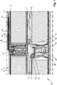
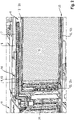
- FIG. 1 shows a section of a traction battery 10 of a motor vehicle in the area of four battery modules 11, wherein in 1 the battery modules 11 shown are arranged on the one hand side by side and on the other hand one above the other.
- Each battery module 11 has a module housing 12 and battery cells 13 arranged in the module housing 12.
- the battery cells 13 of each battery module 11 are electrically coupled via electrical current conductors. These electrical current conductors, which serve to electrically couple the battery cells 13 of a respective battery module 11, are also referred to as busbars.
- the battery modules 11 are also electrically coupled, specifically via busbars, the in 1 shown busbars 14, 15 in 2 or in 3 are shown in greater detail.
- the aim of the invention is to effectively dissipate heat from the electrical busbars, which serve to electrically couple the battery modules 11, in order to protect them from thermal overload.
- At least one heat-conducting body is arranged between a respective electrical busbar, which serves to electrically couple the battery modules 11 of the traction battery 10, and an adjacent housing of the traction battery 10 or an adjacent structural component of a body of the motor vehicle or an adjacent module housing 12 of an adjacent battery module 11, wherein Heat can be dissipated from the respective busbar in the direction of the respective adjacent component via this heat-conducting body.
- the respective adjoining component i.e. the adjoining housing of the traction battery 10 or the adjoining structural component of the body of the motor vehicle or the adjoining module housing 12, is preferably actively cooled and/or coupled to an actively cooled component, in which case the heat is particularly effective in this case can be discharged.
- An actively cooled component is in particular a liquid-cooled component, such as a water-cooled component.
- In 2 is the detail II of 1 shown in the area of a first electrical busbar 14, which is the electrical contact of the in 2 shown battery module 11 is used with another battery module 11, these two to be electrically coupled via the first electrical busbar 14 battery modules 11 in 1 are arranged directly next to each other in an upper level.
- the electric busbar 14 shown which serves to electrically couple two battery modules 11, has a busbar core 16 made of an electrically conductive material, such as copper, and a busbar housing 17 surrounding the busbar core 16 at a distance and made of an electrically non-conductive material, such as Example of plastic, on.
- a first heat-conducting body 18 thermally couples the busbar core 16 to the busbar housing 17.
- a second heat-conducting body 19 is arranged between the busbar housing 17 and the adjoining module housing 12 of the battery module 11 , which thermally couples the busbar 14 to the battery module housing 12 of the battery module 11 .
- the busbar 14 shown is thermally coupled to a cover 12a of the module housing 12 of the battery module 11, this cover 12a being thermally coupled via side walls 12b of the module housing 12 to a bottom wall 12c of the module housing 12, which is thermally coupled to an actively cooled assembly 20.
- This actively cooled assembly 20 is in 1 , 2 to an assembly that is below the in 2 battery module 11 shown and above the battery module 11 arranged under this battery module 11 (see 1 ) is arranged.
- This assembly 20 is either an assembly of a battery housing or a structural component of a body of the motor vehicle.
- the respective first heat-conducting body 18, which is arranged between the respective busbar core 16 and the respective busbar housing 17 of the electric busbar 14, is a casting compound body made of a heat-conducting compound which, in a liquid state, is in a cavity between the busbar core 16 and the busbar housing 17 is arranged and hardens there.
- the respective second heat-conducting body 19 which is located between the respective busbar housing 17 and the adjacent component in 2 is arranged between the conductor rail housing 17 and the cover 12a of the module housing 12, it is preferably a heat-conducting pad.
- FIG. 1 and 2 show a frame component 21 between the battery modules 11 shown there, it being possible for this frame component 21 to be a side wall of a housing of the traction battery or a structural component of the body of the motor vehicle.
- 1 11 also shows between the battery modules 11 of the lower tier of battery modules 11 a frame component 22 which is either a side wall of the housing of the traction battery or an adjacent structural component of the body of the motor vehicle.
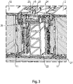
- FIG 3 shows the detail III of 1 from the traction battery 10 in the area of the battery modules 11 in 1 shown lower layer of battery modules 11, specifically in the area of a busbar 15, which is the electrical coupling of the in 3 Battery modules 11 shown is used.
- This busbar 15 also has a busbar core 23 made of an electrically conductive material, such as copper, and a busbar housing 24 made of a non-electrically conductive material, such as plastic, surrounding the busbar core 23 at a distance on the outside.
- a busbar core 23 made of an electrically conductive material, such as copper
- a busbar housing 24 made of a non-electrically conductive material, such as plastic, surrounding the busbar core 23 at a distance on the outside.
- the busbar housing 24 surrounds the busbar core 23 on the outside, with in 3 in accordance to 2 a first heat-conducting body 25 is arranged on the one hand between the busbar core 23 and the busbar housing 24 and a second heat-conducting body 26 is arranged on the other hand between the busbar housing 24 and the adjacent frame component 22 .
- the first thermally conductive body 25 is preferably in turn a casting compound body and the second thermally conductive body 26 is preferably in turn a thermally conductive pad.
- busbar core 23 is the in 3 Busbar 15 shown is thermally coupled to frame member 22 via busbar housing 24 , wherein frame member 22 is thermally coupled to actively cooled assembly 27 extending below frame member 22 and below battery modules 11 .
- This actively cooled component 27 is a floor component, either of the traction battery housing or of the body of the motor vehicle.
- 4 shows a modification of the detail III 3 in the area of the busbar 15, where in 4 the busbar 15 is not thermally coupled to the frame component 22, but rather to a cover component 28. Accordingly, in 4 the first heat-conducting body 25 is in turn arranged between the busbar core 23 and the busbar housing 24 , the second heat-conducting body 26 is arranged between the busbar housing 24 and the cover component 28 .
- Busbar 15 shown is therefore used for electrical contacting of the two in 3 and 4 shown, positioned side by side battery modules 11.
- FIG 5 shows a further detail from a traction battery 10 according to the invention in the area of a battery module 11, this battery module 11 being arranged between two frame components 30, 31.
- These frame components 30, 31 can in turn be either a side wall of a battery housing of the traction battery or structural components of a body of the motor vehicle.
- Two busbars 32 , 33 extend above the battery module 11 , each of these busbars 32 , 33 serving to electrically contact battery modules 11 of the traction battery 10 .
- Each of these busbars 32, 33 has a busbar core 34 made of an electrically conductive material, such as copper, and a busbar jacket 35 made of an electrically non-conductive material, such as plastic or rubber, surrounding the respective busbar core 34 on the outside.
- a busbar core 34 made of an electrically conductive material, such as copper
- a busbar jacket 35 made of an electrically non-conductive material, such as plastic or rubber, surrounding the respective busbar core 34 on the outside.
- a heat-conducting body 36 is arranged between the busbar jacket 35 of the respective busbar 32, 33 and an adjacent component.
- This thermally conductive body 36 is preferably a casting compound body.
- the casting compound body 36 thermally couples the respective conductor rail 32, 33 on the one hand directly to a cover component 37 and on the other hand indirectly via an EMC carrier 38, in particular to the frame component 31, which is a side wall of the housing of the traction battery or an adjacent structural component of the body of the motor vehicle.
- the cover component 37 and/or the frame component 31 are thermally coupled to an actively cooled component, in particular to a liquid-cooled component, as has already been described in connection with the details of FIG 2 , 3 and 4 was described.
- heat can be effectively dissipated from busbars 14, 15, 32, 33 of a traction battery 10 of a motor vehicle in order to avoid an impermissibly high thermal load on the busbars 14, 15, 32, 33.
- a higher electrical current can flow via the conductor rails 14, 15, 32, 33 without the risk of thermal overload.
- an electric vehicle or hybrid vehicle can be operated more effectively, especially when charging the traction battery.
Landscapes
- Chemical & Material Sciences (AREA)
- Chemical Kinetics & Catalysis (AREA)
- Electrochemistry (AREA)
- General Chemical & Material Sciences (AREA)
- Engineering & Computer Science (AREA)
- Manufacturing & Machinery (AREA)
- Sustainable Development (AREA)
- Sustainable Energy (AREA)
- Power Engineering (AREA)
- Transportation (AREA)
- Mechanical Engineering (AREA)
- Life Sciences & Earth Sciences (AREA)
- Aviation & Aerospace Engineering (AREA)
- Electric Propulsion And Braking For Vehicles (AREA)
- Arrangement Or Mounting Of Propulsion Units For Vehicles (AREA)
Abstract
Description
- Die Erfindung betrifft eine Traktionsbatterie eines Kraftfahrzeugs.
- Eine Traktionsbatterie eines als Elektrofahrzeug oder Hybridfahrzeug ausgebildeten Kraftfahrzeugs dient der Speicherung elektrischer Antriebsenergie für das Kraftfahrzeug. Eine solche Traktionsbatterie verfügt über mehrere Batteriemodule, wobei jedes Batteriemodul ein Modulgehäuse und vom Modulgehäuse aufgenommene Batteriezellen aufweist. Eine Traktionsbatterie kann ein Batteriegehäuse aufweisen, welches die Batteriemodule aufnimmt und gegenüber einer Umgebung abdichtet. Ist kein separates Batteriegehäuse vorhanden, dichten die Modulgehäuse der Batteriemodule die Batteriezellen für jedes Batteriemodul individuell gegenüber der Umgebung ab, wobei dann Strukturbauteile einer Karosserie des Kraftfahrzeugs strukturversteifende Funktionen eines Batteriegehäuses übernehmen.
- Die Batteriezellen jedes Batteriemoduls einer Traktionsbatterie sind untereinander über elektrische Stromleiter gekoppelt, die als Busbar bezeichnet werden. Diese als Busbar bezeichneten elektrischen Stromleiter, die der elektrischen Kopplung der Batteriezellen eines jeweiligen Batteriemoduls dienen, erstrecken sich innerhalb des Modulgehäuses des jeweiligen Batteriemoduls.
- Die Batteriemodule einer Traktionsbatterie sind über elektrische Stromschienen elektrisch gekoppelt. Die elektrischen Stromschienen erstrecken sich dabei außerhalb der Modulgehäuse der zu koppelnden Batteriemodule.
- Die elektrischen Stromschienen, die der elektrischen Kopplung der Batteriemodule einer Traktionsbatterie dienen, übertragen hohe elektrische Ströme. Daher sind diese elektrischen Stromschienen auch einer hohen Erwärmung ausgesetzt. Bislang bereitet es Schwierigkeiten, die Wärme von den elektrischen Stromschienen, die der elektrischen Kopplung der Batteriemodule einer Traktionsbatterie dienen, effizient abzuführen.
- Aus der
DE 10 2019 122 754 A1 ist ein Batteriemodul einer Traktionsbatterie eines Kraftfahrzeugs bekannt. Das Batteriemodul verfügt über mehrere Batteriezellen, die über eine Busbar elektrisch gekoppelt sind. Die Busbar besteht aus Kupfer und ist mit einem Kühlkörper thermisch leitend verbunden. So kann von der jeweiligen Busbar Wärme abgeführt werden. - Aus der
US 2020/0136326 A1 ist eine elektrische Einheit mit einem elektrischen Kontakt und an den elektrischen Kontakt angeschlossenen Busbars bekannt. Die an den elektrischen Kontakt angeschlossenen Busbars sind mit einem Kühlkörper verbunden. Der Kühlkörper ist dabei zwischen den Busbars und dem elektrischen Kontakt positioniert. - Aus dem Stand der Technik sind zwar Ausführungen bekannt, um Busbars, die der elektrischen Koppung der Batteriezellen eines Batteriemoduls einer Traktionsbatterie dienen, zu kühlen, aus dem Stand der Technik sind jedoch keine Ausführungen bekannt, um die elektrischen Stromschienen einer Traktionsbatterie eines Kraftfahrzeugs, die der elektrischen Kopplung der Batteriemodule der Traktionsbatterie dienen, vor einer thermischen Überlastung effektiv zu schützen.
- Aufgabe der Erfindung ist es, eine neuartige Traktionsbatterie eines Kraftfahrzeugs zu schaffen, bei welcher die elektrischen Stromschienen, die der elektrischen Kopplung der Batteriemodule der Traktionsbatterie dienen, vor einer thermischen Überlastung effektiv geschützt sind.
- Diese Aufgabe wird durch eine Traktionsbatterie nach Patentanspruch 1 gelöst.
- Erfindungsgemäß ist zwischen den elektrischen Stromschienen, die der elektrischen Kopplung der Batteriemodule dienen, und einem angrenzenden Gehäuse der Traktionsbatterie oder einem angrenzenden Strukturbauteil einer Karosserie des Kraftfahrzeugs oder einem angrenzenden Modulgehäuse eines Batteriemoduls mindestens ein Wärmleitkörper angeordnet ist.
- Mit der hier vorliegenden Erfindung wird erstmals vorgeschlagen, zwischen den elektrischen Stromschienen, die der elektrischen Kopplung von Batteriemodulen einer Traktionsbatterie dienen, und einem angrenzenden Bauteil mindestens einen Wärmeleitkörper anzuordnen, um über diesen Wärmeleitkörper Wärme von der jeweiligen elektrischen Stromschiene an das jeweilige angrenzende Bauteil abzuleiten und so die elektrische Stromschiene vor einer zu starken thermischen Belastung zu schützen.
- Das angrenzende Gehäuse der Traktionsbatterie oder das angrenzende Strukturbauteil der Karosserie des Kraftfahrzeugs oder das angrenzende Modulgehäuse des Batteriemoduls ist vorzugsweise aktiv gekühlt, insbesondere flüssigkeitsgekühlt, und/oder mit einem aktiv gekühlten, insbesondere flüssigkeitsgekühlten Bauteil, gekoppelt. Hiermit kann die Wärme besonders vorteilhaft abgeführt werden.
- Nach einer ersten vorteilhaften Weiterbildung weist mindestens eine der elektrischen Stromschienen, die der elektrischen Kopplung der Batteriemodule der Traktionsbatterie dienen, einen Stromschienenkern aus einem elektrisch leitfähigen Werkstoff und ein den Stromschienenkern außen mit Abstand umgebendes Stromschienengehäuse aus einem elektrisch nicht leitfähigen Werkstoff auf. Zwischen dem Stromschienenkern und dem Stromschienengehäuse der jeweiligen elektrischen Stromschiene ist ein erster Wärmleitkörper angeordnet. Zwischen dem Stromschienengehäuse der jeweiligen elektrischen Stromschiene und dem angrenzenden Gehäuse der Traktionsbatterie oder dem angrenzenden Strukturbauteil der Karosserie des Kraftfahrzeugs oder dem angrenzenden Modulgehäuse des jeweiligen Batteriemoduls ist ein zweiter Wärmleitkörper angeordnet. Bei den elektrischen Stromschienen nach der ersten vorteilhaften Weiterbildung handelt es sich insbesondere um solche Stromschienen einer Traktionsbatterie, die relativ kurz sind und der elektrischen Kopplung von insbesondere unmittelbar benachbarten Batteriemodulen der Traktionsbatterie dienen.
- Nach einer zweiten vorteilhaften Weiterbildung weist mindestens eine der elektrischen Stromschienen, die der elektrischen Kopplung der Batteriemodule der Traktionsbatterie dienen, einen Stromschienenkern aus einem elektrisch leitfähigen Werkstoff und einen den Stromschienenkern außen umgebenden Stromschienenmantel aus einem elektrisch nicht leitfähigen Werkstoff auf, der direkt am Stromschienenkern der jeweiligen elektrischen Stromschiene anliegt. Zwischen dem Stromschienenmantel der jeweiligen elektrischen Stromschiene und dem angrenzenden Gehäuse der Traktionsbatterie oder dem angrenzenden Strukturbauteil der Karosserie des Kraftfahrzeugs oder dem angrenzenden Modulgehäuse des jeweiligen Batteriemoduls ist ein Wärmleitkörper angeordnet. Bei den elektrischen Stromschienen nach der zweiten vorteilhaften Weiterbildung der Erfindung handelt es sich insbesondere um Stromschienen, die relativ lang ausgebildet sind und insbesondere weiter beabstandete Batteriemodule der Traktionsbatterie miteinander elektrisch koppeln.
- Vorzugsweise koppelt bei der zweiten vorteilhaften Weiterbildung der jeweilige Wärmleitkörper die jeweilige Stromschiene direkt an ein Deckelbauteil oder Bodenbauteil, zusätzlich über einen EMV-Träger indirekt an ein Rahmenbauteil, welches eine Seitenwand des Gehäuses der Traktionsbatterie oder das angrenzenden Strukturbauteil der Karosserie bildet. Hiermit kann über zwei Pfade Wärme von der jeweiligen Stromschiene abgeführt werden.
- Bevorzugte Weiterbildungen der Erfindung ergeben sich aus den Unteransprüchen und der nachfolgenden Beschreibung. Ausführungsbeispiele der Erfindung werden, ohne hierauf beschränkt zu sein, an Hand der Zeichnung näher erläutert. Dabei zeigt:
- Fig. 1
- einen Ausschnitt aus einer Traktionsbatterie im Bereich von vier Batteriemodulen, die nebeneinander und übereinander angeordnet sind,
- Fig. 2
- ein erstes Detail II der
Fig. 1 im Bereich eines Batteriemoduls und einer Stromschiene, die der Kopplung des Batteriemoduls mit einem anderen Batteriemodul dient, - Fig. 3
- ein zweites Detail III der
Fig. 1 im Bereich eines Batteriemoduls und einer Stromschiene, die der Kopplung des Batteriemoduls mit einem anderen Batteriemodul dient, - Fig. 4
- eine Abwandlung des Details III der
Fig. 3 , - Fig. 5
- einen weiteren Ausschnitt aus einer Traktionsbatterie im Bereich eines Batteriemoduls und im Bereich von Stromschienen, die der Kopplung des Batteriemoduls mit einem anderen Batteriemodul dienen.
- Die Erfindung betrifft eine Traktionsbatterie eines Kraftfahrzeugs. Eine solche Traktionsbatterie eines Kraftfahrzeugs dient der Speicherung elektrischer Antriebsenergie für das Kraftfahrzeug. Eine Traktionsbatterie verfügt über mehrere Batteriemodule, wobei jedes Batteriemodul über mehrere Batteriezellen verfügt.
-
Fig. 1 zeigt einen Ausschnitt aus einer Traktionsbatterie 10 eines Kraftfahrzeugs im Bereich von vier Batteriemodulen 11, wobei inFig. 1 die gezeigten Batteriemodule 11 einerseits nebeneinander und andererseits übereinander angeordnet sind. Jedes Batteriemodul 11 verfügt über ein Modulgehäuse 12 sowie über im Modulgehäuse 12 angeordnete Batteriezellen 13. Die Batteriezellen 13 eines jeden Batteriemoduls 11 sind über elektrische Stromleiter elektrisch gekoppelt. Diese elektrischen Stromleiter, die der elektrischen Kopplung der Batteriezellen 13 eines jeweiligen Batteriemoduls 11 dienen, werden auch als Busbar bezeichnet. - In einer Traktionsbatterie 10 sind auch die Batteriemodule 11 elektrisch gekoppelt, und zwar über Stromschienen, wobei die in
Fig. 1 gezeigten Stromschienen 14, 15 inFig. 2 bzw. inFig. 3 in größerem Detail gezeigt sind. - Bei der Erfindung geht es darum, von den elektrischen Stromschienen, die der elektrischen Kopplung der Batteriemodule 11 dienen, Wärme effektiv abzuführen, um dieselben vor einer thermischen Überlastung zu schützen.
- Erfindungsgemäß ist zwischen einer jeweiligen elektrischen Stromschiene, die der elektrischen Kopplung der Batteriemodule 11 der Traktionsbatterie 10 dient, und einem angrenzenden Gehäuse der Traktionsbatterie 10 oder einem angrenzenden Strukturbauteil einer Karosserie des Kraftfahrzeugs oder einem angrenzenden Modulgehäuse 12 eines angrenzenden Batteriemoduls 11 mindestens ein Wärmeleitkörper angeordnet, wobei über diesen Wärmeleitkörper Wärme von der jeweiligen Stromschiene in Richtung auf das jeweilige angrenzende Bauteil abgeführt werden kann.
- Dabei ist das jeweilige angrenzende Bauteil, also das angrenzende Gehäuse der Traktionsbatterie 10 oder das angrenzende Strukturbauteil der Karosserie des Kraftfahrzeugs oder das angrenzende Modulgehäuse 12, vorzugsweise aktiv gekühlt und/oder mit einem aktiv gekühlten Bauteil gekoppelt, wobei dann in diesem Fall die Wärme besonders effektiv abgeführt werden kann.
- Bei einem aktiv gekühlten Bauteil handelt es sich insbesondere um ein flüssigkeitsgekühltes Bauteil, wie wassergekühltes Bauteil.
- In
Fig. 2 ist das Detail II derFig. 1 im Bereich einer ersten elektrischen Stromschiene 14 gezeigt, die der elektrischen Kontaktierung des inFig. 2 gezeigten Batteriemoduls 11 mit einem anderen Batteriemodul 11 dient, wobei diese beiden über die erste elektrische Stromschiene 14 elektrisch zu koppelnden Batteriemodule 11 inFig. 1 in einer oberen Ebene unmittelbar nebeneinander angeordnet sind. - Die in
Fig. 2 gezeigte elektrische Stromschiene 14, die der elektrischen Kopplung zweier Batteriemodule 11 dient, weist einen Stromschienenkern 16 aus einem elektrisch leitfähigen Werkstoff, wie zum Beispiel aus Kupfer, und ein den Stromschienenkern 16 außen mit Abstand umgebendes Stromschienengehäuse 17 aus einem elektrisch nicht leitfähigen Werkstoff, wie zum Beispiel aus Kunststoff, auf. - Zwischen dem Stromschienenkern 16 und dem Stromschienengehäuse 17 der in
Fig. 2 gezeigten Stromschiene 14 ist ein erster Wärmeleitkörper 18 angeordnet, wobei dieser Wärmeleitkörper 18 den Stromschienenkern 16 mit dem Stromschienengehäuse 17 thermisch koppelt. Zusätzlich ist zwischen dem Stromschienengehäuse 17 und dem angrenzenden Modulgehäuse 12 des Batteriemoduls 11 ein zweiter Wärmeleitkörper 19 angeordnet, welcher die Stromschiene 14 an das Batteriemodulgehäuse 12 des Batteriemoduls 11 thermisch koppelt. - Dabei ist in
Fig. 2 die gezeigte Stromschiene 14 mit einem Deckel 12a des Modulgehäuses 12 des Batteriemoduls 11 thermisch gekoppelt, wobei dieser Deckel 12a über Seitenwände 12b des Modulgehäuses 12 mit einer Bodenwand 12c des Modulgehäuses 12 thermisch gekoppelt ist, die mit einer aktiv gekühlten Baugruppe 20 thermisch gekoppelt ist. Bei dieser aktiv gekühlten Baugruppe 20 handelt es sich inFig. 1 ,2 um eine Baugruppe, die unterhalb des inFig. 2 gezeigten Batteriemoduls 11 und oberhalb des unter diesem Batteriemodul 11 angeordneten Batteriemoduls 11 (sieheFig. 1 ) angeordnet ist. Bei dieser Baugruppe 20 handelt es sich entweder um eine Baugruppe eines Batteriegehäuses oder um ein Strukturbauteil einer Karosserie des Kraftfahrzeugs. - Bei dem jeweiligen ersten Wärmeleitkörper 18, der zwischen dem jeweiligen Stromschienenkern 16 und dem jeweiligen Stromschienengehäuse 17 der elektrischen Stromschiene 14 angeordnet ist, handelt es sich um einen Vergussmassekörper aus einer Wärmeleitmasse, die in flüssigem Zustand in einem Hohlraum zwischen dem Stromschienenkern 16 und dem Stromschienengehäuse 17 angeordnet wird und dort aushärtet.
- Bei dem jeweiligen zweiten Wärmeleitkörper 19, der zwischen dem jeweiligen Stromschienengehäuse 17 und dem angrenzenden Bauteil, in
Fig. 2 zwischen dem Stromschienengehäuse 17 und dem Decke 12a des Modulgehäuses 12 angeordnet ist, handelt es sich vorzugsweise um ein Wärmeleitpad. -
Fig. 1 und2 zeigen zwischen den dort gezeigten Batteriemodulen 11 ein Rahmenbauteil 21, wobei es sich bei diesem Rahmenbauteil 21 um eine Seitenwand eines Gehäuses der Traktionsbatterie oder um ein Strukturbauteil der Karosserie des Kraftfahrzeugs handeln kann. -
Fig. 1 zeigt auch zwischen den Batteriemodulen 11 der unteren Lage aus Batteriemodulen 11 ein Rahmenbauteil 22, bei welchem es sich entweder um eine Seitenwand des Gehäuses der Traktionsbatterie oder um ein angrenzendes Strukturbauteil der Karosserie des Kraftfahrzeugs handelt. -
Fig. 3 zeigt das Detail III derFig. 1 aus der Traktionsbatterie 10 im Bereich der Batteriemodule 11 der inFig. 1 gezeigten unteren Lage aus Batteriemodulen 11, und zwar im Bereich einer Stromschiene 15, die der elektrischen Kopplung der inFig. 3 gezeigten Batteriemodule 11 dient. - Auch diese Stromschiene 15 verfügt über einen Stromschienenkern 23 aus einem elektrisch leitfähigen Werkstoff, wie zum Beispiel aus Kupfer, und ein den Stromschienenkern 23 außen mit Abstand umgebendes Stromschienengehäuse 24 aus einem nicht elektrisch leitenden Werkstoff, wie zum Beispiel aus Kunststoff.
- Das Stromschienengehäuse 24 umgibt den Stromschienenkern 23 außen, wobei in
Fig. 3 in Übereinstimmung zurFig. 2 einerseits zwischen dem Stromschienenkern 23 und dem Stromschienengehäuse 24 ein erster Wärmeleitkörper 25 und andererseits zwischen dem Stromschienengehäuse 24 und dem angrenzenden Rahmenbauteil 22 ein zweiter Wärmeleitkörper 26 angeordnet ist. - Bei dem ersten Wärmeleitkörper 25 handelt es sich vorzugsweise wiederum um einen Vergussmassekörper und bei dem zweiten Wärmeleitkörper 26 vorzugsweise wiederum um ein Wärmeleitpad.
- Auf diese Art und Weise ist der Stromschienenkern 23 der in
Fig. 3 gezeigten Stromschiene 15 thermisch über das Stromschienengehäuse 24 mit dem Rahmenbauteil 22 gekoppelt, wobei das Rahmenbauteil 22 thermisch mit der aktiv gekühlten Baugruppe 27 gekoppelt ist, die sich unterhalb des Rahmenbauteils 22 und unterhalb der Batteriemodule 11 erstreckt. - Bei diesem aktiv gekühlten Bauteil 27 handelt es sich um ein Bodenbauteil, entweder des Gehäuses der Traktionsbatterie oder der Karosserie des Kraftfahrzeugs.
-
Fig. 4 zeigt eine Abwandlung des Details III derFig. 3 im Bereich der Stromschiene 15, wobei inFig. 4 die Stromschiene 15 nicht an das Rahmenbauteil 22 thermisch gekoppelt ist, sondern vielmehr an ein Deckelbauteil 28. Demnach ist inFig. 4 der erste Wärmeleitkörper 25 wiederum zwischen dem Stromschienenkern 23 und dem Stromschienengehäuse 24 angeordnet, der zweite Wärmeleitkörper 26 ist zwischen dem Stromschienengehäuse 24 und dem Deckelbauteil 28 angeordnet. - In
Fig. 3 und4 ist die Kontaktierung des Stromschienenkerns 23 mit elektrischen Anschlüssen 29 der Batteriemodule 11 gut erkennbar. Die inFig. 3 und4 gezeigte Stromschiene 15 dient demnach der elektrischen Kontaktierung der beiden inFig. 3 und4 gezeigten, nebeneinander positionierten Batteriemodule 11. -
Fig. 5 zeigt ein weiteres Detail aus einer erfindungsgemäßen Traktionsbatterie 10 im Bereich eines Batteriemoduls 11, wobei dieses Batteriemodul 11 zwischen zwei Rahmenbauteilen 30, 31 angeordnet ist. Bei diesen Rahmenbauteilen 30, 31 kann es sich wiederum entweder um eine Seitenwand eines Battriegehäuses der Traktionsbatterie oder um Strukturbauteile einer Karosserie des Kraftfahrzeugs handeln. Oberhalb des Batteriemoduls 11 erstrecken sich zwei Stromschienen 32, 33, wobei jede dieser Stromschienen 32, 33 der elektrischen Kontaktierung von Batteriemodulen 11 der Traktionsbatterie 10 dient. - Jede dieser Stromschienen 32, 33 verfügt über einen Stromschienenkern 34 aus einem elektrisch leitfähigen Werkstoff, wie zum Beispiel aus Kupfer, und über einen den jeweiligen Stromschienenkern 34 außen umgebenden Stromschienenmantel 35 aus einem elektrisch nicht leitfähigen Werkstoff, wie zum Beispiel aus Kunststoff oder Gummi. Bei den elektrischen Stromschienen 32, 33 der
Fig. 5 liegt der jeweilige Stromschienenmantel 35 direkt bzw. unmittelbar am jeweiligen Stromschienenkern 34 an, ohne dass zwischen denselben ein Hohlraum ausgebildet ist. Zwischen dem Stromschienenmantel 35 der jeweiligen Stromschiene 32, 33 und einem angrenzenden Bauteil ist ein Wärmeleitkörper 36 angeordnet. Bei diesem Wärmeleitkörper 36 handelt es sich vorzugsweise um einen Vergussmassekörper. - In
Fig. 5 koppelt der Vergussmassekörper 36 die jeweilige Stromschiene 32, 33 thermisch einerseits direkt an ein Deckelbauteil 37 und andererseits indirekt über einen EMV-Träger 38 insbesondere an das Rahmenbauteil 31, bei welchem es sich um eine Seitenwand des Gehäuses der Traktionsbatterie oder um ein angrenzendes Strukturbauteil der Karosserie des Kraftfahrzeugs handelt. Das Deckelbauteil 37 und/oder das Rahmenbauteil 31 sind thermisch mit einem aktiv gekühlten Bauteil gekoppelt, insbesondere mit einem flüssigkeitsgekühlten Bauteil, wie dies bereits im Zusammenhang mit den Details derFig. 2 ,3 und4 beschrieben wurde. - Mit der Erfindung kann von Stromschienen 14, 15, 32, 33 einer Traktionsbatterie 10 eines Kraftfahrzeugs effektiv Wärme abgeführt werden, um eine unzulässig hohe thermische Belastung der Stromschienen 14, 15, 32, 33 zu vermeiden. Über die Stromschienen 14, 15, 32, 33 kann ein höherer elektrischer Strom fließen, ohne die Gefahr einer thermischen Überbelastung. So kann ein Elektrofahrzeug oder Hybridfahrzeug effektiver betrieben werden, insbesondere beim Laden der Traktionsbatterie. Beim Laden kann länger mit höherer Ladeleistung gearbeitet werden. Dies kann selbstverständlich auch beim Entladen erfolgen.
Claims (10)
- Traktionsbatterie (10) eines Kraftfahrzeugs,mit mehreren Batteriemodulen (11),wobei die Batteriemodule (11) der Traktionsbatterie (12) über elektrische Stromschienen (14, 15, 32, 33) elektrisch gekoppelt sind,wobei jedes Batteriemodul (11) ein Modulgehäuse (12) und im jeweiligen Modulgehäuse (12) aufgenommene Batteriezellen (13) aufweist,wobei die Batteriezellen (13) jedes Batteriemoduls 12) elektrisch gekoppelt sind,dadurch gekennzeichnet, dasszwischen den elektrischen Stromschienen (14, 15, 32, 33), die der elektrischen Kopplung der Batteriemodule (11) dienen, und einem angrenzenden Gehäuse der Traktionsbatterie oder einem angrenzenden Strukturbauteil einer Karosserie des Kraftfahrzeugs oder einem angrenzenden Modulgehäuse (12) eines Batteriemoduls (11) mindestens ein Wärmleitkörper (18, 19, 25, 26, 36) angeordnet ist.
- Traktionsbatterie nach Anspruch 1, dadurch gekennzeichnet, dassmindestens eine der elektrischen Stromschienen (14, 15), die der elektrischen Kopplung der Batteriemodule (11) dienen, einen Stromschienenkern (16, 23) aus einem elektrisch leitfähigen Werkstoff und ein den Stromschienenkern (16, 23) außen umgebendes Stromschienengehäuse (17, 24) aus einem elektrisch nicht leitfähigen Werkstoff aufweist,zwischen dem Stromschienenkern (16, 23) und dem Stromschienengehäuse (17, 24) der jeweiligen elektrischen Stromschiene (14, 15) ein erster Wärmleitkörper (18, 25) angeordnet ist,zwischen dem Stromschienengehäuse (17, 24) der jeweiligen elektrischen Stromschiene (14, 15) und dem angrenzenden Gehäuse der Traktionsbatterie oder dem angrenzenden Strukturbauteil der Karosserie des Kraftfahrzeugs oder dem angrenzenden Modulgehäuse (12) des jeweiligen Batteriemoduls (11) ein zweiter Wärmleitkörper (19, 26) angeordnet ist.
- Traktionsbatterie nach Anspruch 2, dadurch gekennzeichnet, dass der jeweilige erste Wärmleitkörper (18, 25) ein Vergussmassekörper ist.
- Traktionsbatterie nach Anspruch 2 oder 3, dadurch gekennzeichnet, dass der jeweilige zweite Wärmleitkörper (19, 26) ein Wärmeleitpad ist.
- Traktionsbatterie nach einem der vorhergehenden Ansprüche, dadurch gekennzeichnet, dassmindestens eine der elektrischen Stromschienen (32, 33), die der elektrischen Kopplung der Batteriemodule (11) dienen, einen Stromschienenkern (34) aus einem elektrisch leitfähigen Werkstoff und einen den Stromschienenkern (34) außen umgebenden Stromschienenmantel (35) aus einem elektrisch nicht leitfähigen Werkstoff aufweist, der direkt am Stromschienenkern (34) der jeweiligen elektrischen Stromschiene (32, 33) anliegt,zwischen dem Stromschienenmantel (34) der jeweiligen elektrischen Stromschiene (32, 33) und dem angrenzenden Gehäuse der Traktionsbatterie oder dem angrenzenden Strukturbauteil der Karosserie des Kraftfahrzeugs oder dem angrenzenden Modulgehäuse (12) des jeweiligen Batteriemoduls (11) ein Wärmleitkörper (36) angeordnet ist.
- Traktionsbatterie nach Anspruch 5, dadurch gekennzeichnet, dass der jeweilige Wärmleitkörper (36) ein Vergussmassekörper ist.
- Traktionsbatterie nach Anspruch 5 oder 6, dadurch gekennzeichnet, dass der jeweilige Wärmleitkörper (36) die jeweilige Stromschiene (32, 33) direkt an ein Deckelbauteil (37) oder Bodenbauteil koppelt.
- Traktionsbatterie nach einem der Ansprüche 5 bis 7, dadurch gekennzeichnet, dass der jeweilige Wärmleitkörper (36) die jeweilige Stromschiene (32, 33) über einem EMV-Träger (38) indirekt an ein Rahmenbauteil (31) koppelt, welches eine Seitenwand des Gehäuses der Traktionsbatterie oder das angrenzenden Strukturbauteil der Karosserie bildet.
- Traktionsbatterie nach einem der vorhergehenden Ansprüche, dadurch gekennzeichnet, dass das angrenzende Gehäuse der Traktionsbatterie oder das angrenzende Strukturbauteil der Karosserie des Kraftfahrzeugs oder das angrenzende Modulgehäuse (12) des Batteriemoduls (11) aktiv gekühlt ist und/oder mit einem aktiv gekühlten Bauteil gekoppelt ist.
- Traktionsbatterie nach einem der vorhergehenden Ansprüche, dadurch gekennzeichnet, dass das angrenzende Gehäuse der Traktionsbatterie oder das angrenzende Strukturbauteil der Karosserie des Kraftfahrzeugs oder das angrenzende Modulgehäuse (12) des Batteriemoduls (11) flüssigkeitsgekühlt ist und/oder mit einem flüssigkeitsgekühlten Bauteil gekoppelt ist.
Applications Claiming Priority (1)
| Application Number | Priority Date | Filing Date | Title |
|---|---|---|---|
| DE102021111099.8A DE102021111099A1 (de) | 2021-04-29 | 2021-04-29 | Traktionsbatterie eines Kraftfahrzeugs |
Publications (2)
| Publication Number | Publication Date |
|---|---|
| EP4084189A1 true EP4084189A1 (de) | 2022-11-02 |
| EP4084189B1 EP4084189B1 (de) | 2024-07-17 |
Family
ID=80446830
Family Applications (1)
| Application Number | Title | Priority Date | Filing Date |
|---|---|---|---|
| EP22020037.2A Active EP4084189B1 (de) | 2021-04-29 | 2022-02-08 | Traktionsbatterie eines kraftfahrzeuges |
Country Status (4)
| Country | Link |
|---|---|
| US (1) | US12463293B2 (de) |
| EP (1) | EP4084189B1 (de) |
| CN (1) | CN115275492B (de) |
| DE (1) | DE102021111099A1 (de) |
Citations (5)
| Publication number | Priority date | Publication date | Assignee | Title |
|---|---|---|---|---|
| DE102007063178A1 (de) * | 2007-12-20 | 2009-06-25 | Daimler Ag | Batterie mit Wärmeleitplatte zum Temperieren der Batterie |
| WO2018105610A1 (ja) * | 2016-12-05 | 2018-06-14 | トヨタ自動車株式会社 | リレーユニット |
| DE102019122754A1 (de) | 2019-08-23 | 2019-10-10 | FEV Group GmbH | Batteriemodul |
| WO2020028931A1 (de) * | 2018-08-07 | 2020-02-13 | Voltlabor Gmbh | Batterie |
| US20200136326A1 (en) | 2018-10-31 | 2020-04-30 | Lear Corporation | Electrical unit |
Family Cites Families (4)
| Publication number | Priority date | Publication date | Assignee | Title |
|---|---|---|---|---|
| JP6439710B2 (ja) | 2016-01-27 | 2018-12-19 | 株式会社オートネットワーク技術研究所 | バスバーモジュール |
| WO2018165133A1 (en) | 2017-03-08 | 2018-09-13 | Paragon Space Development Corporation | Systems and methods for integrating a busbar and coldplate for battery cooling |
| DE102018219466A1 (de) * | 2018-11-14 | 2020-05-14 | Audi Ag | Verfahren zum Herstellen einer Stromführungseinrichtung, Anschlussdose für eine Fahrzeugbatterie und Kraftfahrzeug |
| DE102020111189A1 (de) | 2020-04-24 | 2021-10-28 | Auto-Kabel Management Gmbh | Kühlsystem für Stromschienen |
-
2021
- 2021-04-29 DE DE102021111099.8A patent/DE102021111099A1/de active Pending
-
2022
- 2022-02-08 EP EP22020037.2A patent/EP4084189B1/de active Active
- 2022-04-26 CN CN202210444685.3A patent/CN115275492B/zh active Active
- 2022-04-28 US US17/731,315 patent/US12463293B2/en active Active
Patent Citations (5)
| Publication number | Priority date | Publication date | Assignee | Title |
|---|---|---|---|---|
| DE102007063178A1 (de) * | 2007-12-20 | 2009-06-25 | Daimler Ag | Batterie mit Wärmeleitplatte zum Temperieren der Batterie |
| WO2018105610A1 (ja) * | 2016-12-05 | 2018-06-14 | トヨタ自動車株式会社 | リレーユニット |
| WO2020028931A1 (de) * | 2018-08-07 | 2020-02-13 | Voltlabor Gmbh | Batterie |
| US20200136326A1 (en) | 2018-10-31 | 2020-04-30 | Lear Corporation | Electrical unit |
| DE102019122754A1 (de) | 2019-08-23 | 2019-10-10 | FEV Group GmbH | Batteriemodul |
Also Published As
| Publication number | Publication date |
|---|---|
| CN115275492A (zh) | 2022-11-01 |
| CN115275492B (zh) | 2024-12-24 |
| US12463293B2 (en) | 2025-11-04 |
| DE102021111099A1 (de) | 2022-11-03 |
| EP4084189B1 (de) | 2024-07-17 |
| US20220352602A1 (en) | 2022-11-03 |
Similar Documents
| Publication | Publication Date | Title |
|---|---|---|
| WO2010031856A2 (de) | Verbindungsplatine | |
| DE102021109353B3 (de) | Batterieeinrichtung für ein Kraftfahrzeug, Kraftfahrzeug und Verfahren zum Betrieb einer Batterieeinrichtung | |
| DE10303253A1 (de) | Elektrische Energieverteilereinheit für ein elektrisches Verbindergehäuse, sowie zugehöriges elektrisches Verbindergehäuse | |
| DE102021110251B4 (de) | Leistungshalbleiteranordnung und Wechselrichterbrücke mit Leistungshalbleiteranordnung | |
| EP1083599A2 (de) | Leistungshalbleitermodul | |
| DE102022206596B4 (de) | Einzelphasenmodul eines Inverters, Inverter und Leistungselektronik | |
| EP4160898A1 (de) | Inverter mit optimiertem elektromagnetischem verhalten | |
| EP3747069A1 (de) | Energiespeichermodul mit über unisolierte leiterstücke verbundenen energiespeicherzellen und/oder einem kühlsystem, energiespeicherblock und verfahren zum kühlen eines energiespeichermoduls | |
| EP4324079A1 (de) | Gekühltes hochstromsystem | |
| EP0677916A2 (de) | Stromrichteranlage mit flüssigkeits- oder luftgekühlten Leistungshalbleitern und Gleichspannungszwischenkreis | |
| DE102012022140A1 (de) | Verteilerplatte für elektrische Energie, die eine geschützte Verteilungsschiene umfasst | |
| DE4338277C2 (de) | Flüssigkeitsgekühltes Stromrichtermodul mit Beschaltungsbauelementen für abschaltbare Leistungshalbleiter | |
| DE102021118397A1 (de) | Batterie mit integrierter Busbarkühlung und Kraftfahrzeug | |
| DE102022206604B4 (de) | Einzelphasenmodul eines Inverters, Inverter und Leistungselektronik | |
| WO2005004236A1 (de) | Elektronisches leistungsmodul mit gummidichtung und entsprechendes herstellungsverfahren | |
| EP4084189B1 (de) | Traktionsbatterie eines kraftfahrzeuges | |
| DE102022206601B4 (de) | Einzelphasenmodul eines Inverters, Inverter und Leistungselektronik | |
| EP3819980B1 (de) | Batteriesystem | |
| DE102022206599A1 (de) | Einzelphasenmodul eines Inverters, Inverter und Leistungselektronik | |
| DE102022206610A1 (de) | Einzelphasenmodul eines Inverters, Inverter und Leistungselektronik | |
| DE102023213259B3 (de) | Halbleitermodul mit verbesserter Kühlung | |
| DE102022206606B4 (de) | Einzelphasenmodul eines Inverters, Inverter und Leistungselektronik | |
| DE102024113421B4 (de) | Vorrichtung zur Umhausung einer Stromschienenverbindung mit Labyrinthdichtung | |
| DE102020215142B4 (de) | Leistungshalbleitermodul und Antriebsstrang für ein Fahrzeug aufweisend ein derartiges Leistungshalbleitermodul | |
| EP1535803B1 (de) | Zentralelektrik für ein Kraftfahrzeug |
Legal Events
| Date | Code | Title | Description |
|---|---|---|---|
| PUAI | Public reference made under article 153(3) epc to a published international application that has entered the european phase |
Free format text: ORIGINAL CODE: 0009012 |
|
| STAA | Information on the status of an ep patent application or granted ep patent |
Free format text: STATUS: THE APPLICATION HAS BEEN PUBLISHED |
|
| AK | Designated contracting states |
Kind code of ref document: A1 Designated state(s): AL AT BE BG CH CY CZ DE DK EE ES FI FR GB GR HR HU IE IS IT LI LT LU LV MC MK MT NL NO PL PT RO RS SE SI SK SM TR |
|
| STAA | Information on the status of an ep patent application or granted ep patent |
Free format text: STATUS: REQUEST FOR EXAMINATION WAS MADE |
|
| 17P | Request for examination filed |
Effective date: 20230502 |
|
| RBV | Designated contracting states (corrected) |
Designated state(s): AL AT BE BG CH CY CZ DE DK EE ES FI FR GB GR HR HU IE IS IT LI LT LU LV MC MK MT NL NO PL PT RO RS SE SI SK SM TR |
|
| P01 | Opt-out of the competence of the unified patent court (upc) registered |
Effective date: 20230526 |
|
| GRAP | Despatch of communication of intention to grant a patent |
Free format text: ORIGINAL CODE: EPIDOSNIGR1 |
|
| STAA | Information on the status of an ep patent application or granted ep patent |
Free format text: STATUS: GRANT OF PATENT IS INTENDED |
|
| INTG | Intention to grant announced |
Effective date: 20240306 |
|
| GRAS | Grant fee paid |
Free format text: ORIGINAL CODE: EPIDOSNIGR3 |
|
| GRAA | (expected) grant |
Free format text: ORIGINAL CODE: 0009210 |
|
| STAA | Information on the status of an ep patent application or granted ep patent |
Free format text: STATUS: THE PATENT HAS BEEN GRANTED |
|
| AK | Designated contracting states |
Kind code of ref document: B1 Designated state(s): AL AT BE BG CH CY CZ DE DK EE ES FI FR GB GR HR HU IE IS IT LI LT LU LV MC MK MT NL NO PL PT RO RS SE SI SK SM TR |
|
| REG | Reference to a national code |
Ref country code: CH Ref legal event code: EP |
|
| REG | Reference to a national code |
Ref country code: DE Ref legal event code: R096 Ref document number: 502022001220 Country of ref document: DE |
|
| REG | Reference to a national code |
Ref country code: IE Ref legal event code: FG4D Free format text: LANGUAGE OF EP DOCUMENT: GERMAN |
|
| REG | Reference to a national code |
Ref country code: LT Ref legal event code: MG9D |
|
| REG | Reference to a national code |
Ref country code: NL Ref legal event code: MP Effective date: 20240717 |
|
| PG25 | Lapsed in a contracting state [announced via postgrant information from national office to epo] |
Ref country code: PT Free format text: LAPSE BECAUSE OF FAILURE TO SUBMIT A TRANSLATION OF THE DESCRIPTION OR TO PAY THE FEE WITHIN THE PRESCRIBED TIME-LIMIT Effective date: 20241118 |
|
| PG25 | Lapsed in a contracting state [announced via postgrant information from national office to epo] |
Ref country code: NL Free format text: LAPSE BECAUSE OF FAILURE TO SUBMIT A TRANSLATION OF THE DESCRIPTION OR TO PAY THE FEE WITHIN THE PRESCRIBED TIME-LIMIT Effective date: 20240717 |
|
| PG25 | Lapsed in a contracting state [announced via postgrant information from national office to epo] |
Ref country code: PT Free format text: LAPSE BECAUSE OF FAILURE TO SUBMIT A TRANSLATION OF THE DESCRIPTION OR TO PAY THE FEE WITHIN THE PRESCRIBED TIME-LIMIT Effective date: 20241118 Ref country code: NL Free format text: LAPSE BECAUSE OF FAILURE TO SUBMIT A TRANSLATION OF THE DESCRIPTION OR TO PAY THE FEE WITHIN THE PRESCRIBED TIME-LIMIT Effective date: 20240717 |
|
| PG25 | Lapsed in a contracting state [announced via postgrant information from national office to epo] |
Ref country code: NO Free format text: LAPSE BECAUSE OF FAILURE TO SUBMIT A TRANSLATION OF THE DESCRIPTION OR TO PAY THE FEE WITHIN THE PRESCRIBED TIME-LIMIT Effective date: 20241017 |
|
| PG25 | Lapsed in a contracting state [announced via postgrant information from national office to epo] |
Ref country code: FI Free format text: LAPSE BECAUSE OF FAILURE TO SUBMIT A TRANSLATION OF THE DESCRIPTION OR TO PAY THE FEE WITHIN THE PRESCRIBED TIME-LIMIT Effective date: 20240717 Ref country code: PL Free format text: LAPSE BECAUSE OF FAILURE TO SUBMIT A TRANSLATION OF THE DESCRIPTION OR TO PAY THE FEE WITHIN THE PRESCRIBED TIME-LIMIT Effective date: 20240717 Ref country code: GR Free format text: LAPSE BECAUSE OF FAILURE TO SUBMIT A TRANSLATION OF THE DESCRIPTION OR TO PAY THE FEE WITHIN THE PRESCRIBED TIME-LIMIT Effective date: 20241018 |
|
| PG25 | Lapsed in a contracting state [announced via postgrant information from national office to epo] |
Ref country code: BG Free format text: LAPSE BECAUSE OF FAILURE TO SUBMIT A TRANSLATION OF THE DESCRIPTION OR TO PAY THE FEE WITHIN THE PRESCRIBED TIME-LIMIT Effective date: 20240717 |
|
| PG25 | Lapsed in a contracting state [announced via postgrant information from national office to epo] |
Ref country code: LV Free format text: LAPSE BECAUSE OF FAILURE TO SUBMIT A TRANSLATION OF THE DESCRIPTION OR TO PAY THE FEE WITHIN THE PRESCRIBED TIME-LIMIT Effective date: 20240717 |
|
| PG25 | Lapsed in a contracting state [announced via postgrant information from national office to epo] |
Ref country code: IS Free format text: LAPSE BECAUSE OF FAILURE TO SUBMIT A TRANSLATION OF THE DESCRIPTION OR TO PAY THE FEE WITHIN THE PRESCRIBED TIME-LIMIT Effective date: 20241117 |
|
| PG25 | Lapsed in a contracting state [announced via postgrant information from national office to epo] |
Ref country code: HR Free format text: LAPSE BECAUSE OF FAILURE TO SUBMIT A TRANSLATION OF THE DESCRIPTION OR TO PAY THE FEE WITHIN THE PRESCRIBED TIME-LIMIT Effective date: 20240717 |
|
| PG25 | Lapsed in a contracting state [announced via postgrant information from national office to epo] |
Ref country code: RS Free format text: LAPSE BECAUSE OF FAILURE TO SUBMIT A TRANSLATION OF THE DESCRIPTION OR TO PAY THE FEE WITHIN THE PRESCRIBED TIME-LIMIT Effective date: 20241017 Ref country code: ES Free format text: LAPSE BECAUSE OF FAILURE TO SUBMIT A TRANSLATION OF THE DESCRIPTION OR TO PAY THE FEE WITHIN THE PRESCRIBED TIME-LIMIT Effective date: 20240717 |
|
| PG25 | Lapsed in a contracting state [announced via postgrant information from national office to epo] |
Ref country code: RS Free format text: LAPSE BECAUSE OF FAILURE TO SUBMIT A TRANSLATION OF THE DESCRIPTION OR TO PAY THE FEE WITHIN THE PRESCRIBED TIME-LIMIT Effective date: 20241017 Ref country code: PL Free format text: LAPSE BECAUSE OF FAILURE TO SUBMIT A TRANSLATION OF THE DESCRIPTION OR TO PAY THE FEE WITHIN THE PRESCRIBED TIME-LIMIT Effective date: 20240717 Ref country code: NO Free format text: LAPSE BECAUSE OF FAILURE TO SUBMIT A TRANSLATION OF THE DESCRIPTION OR TO PAY THE FEE WITHIN THE PRESCRIBED TIME-LIMIT Effective date: 20241017 Ref country code: LV Free format text: LAPSE BECAUSE OF FAILURE TO SUBMIT A TRANSLATION OF THE DESCRIPTION OR TO PAY THE FEE WITHIN THE PRESCRIBED TIME-LIMIT Effective date: 20240717 Ref country code: IS Free format text: LAPSE BECAUSE OF FAILURE TO SUBMIT A TRANSLATION OF THE DESCRIPTION OR TO PAY THE FEE WITHIN THE PRESCRIBED TIME-LIMIT Effective date: 20241117 Ref country code: HR Free format text: LAPSE BECAUSE OF FAILURE TO SUBMIT A TRANSLATION OF THE DESCRIPTION OR TO PAY THE FEE WITHIN THE PRESCRIBED TIME-LIMIT Effective date: 20240717 Ref country code: GR Free format text: LAPSE BECAUSE OF FAILURE TO SUBMIT A TRANSLATION OF THE DESCRIPTION OR TO PAY THE FEE WITHIN THE PRESCRIBED TIME-LIMIT Effective date: 20241018 Ref country code: FI Free format text: LAPSE BECAUSE OF FAILURE TO SUBMIT A TRANSLATION OF THE DESCRIPTION OR TO PAY THE FEE WITHIN THE PRESCRIBED TIME-LIMIT Effective date: 20240717 Ref country code: ES Free format text: LAPSE BECAUSE OF FAILURE TO SUBMIT A TRANSLATION OF THE DESCRIPTION OR TO PAY THE FEE WITHIN THE PRESCRIBED TIME-LIMIT Effective date: 20240717 Ref country code: BG Free format text: LAPSE BECAUSE OF FAILURE TO SUBMIT A TRANSLATION OF THE DESCRIPTION OR TO PAY THE FEE WITHIN THE PRESCRIBED TIME-LIMIT Effective date: 20240717 |
|
| PG25 | Lapsed in a contracting state [announced via postgrant information from national office to epo] |
Ref country code: DK Free format text: LAPSE BECAUSE OF FAILURE TO SUBMIT A TRANSLATION OF THE DESCRIPTION OR TO PAY THE FEE WITHIN THE PRESCRIBED TIME-LIMIT Effective date: 20240717 Ref country code: SM Free format text: LAPSE BECAUSE OF FAILURE TO SUBMIT A TRANSLATION OF THE DESCRIPTION OR TO PAY THE FEE WITHIN THE PRESCRIBED TIME-LIMIT Effective date: 20240717 Ref country code: RO Free format text: LAPSE BECAUSE OF FAILURE TO SUBMIT A TRANSLATION OF THE DESCRIPTION OR TO PAY THE FEE WITHIN THE PRESCRIBED TIME-LIMIT Effective date: 20240717 |
|
| REG | Reference to a national code |
Ref country code: DE Ref legal event code: R097 Ref document number: 502022001220 Country of ref document: DE |
|
| PG25 | Lapsed in a contracting state [announced via postgrant information from national office to epo] |
Ref country code: EE Free format text: LAPSE BECAUSE OF FAILURE TO SUBMIT A TRANSLATION OF THE DESCRIPTION OR TO PAY THE FEE WITHIN THE PRESCRIBED TIME-LIMIT Effective date: 20240717 |
|
| PG25 | Lapsed in a contracting state [announced via postgrant information from national office to epo] |
Ref country code: CZ Free format text: LAPSE BECAUSE OF FAILURE TO SUBMIT A TRANSLATION OF THE DESCRIPTION OR TO PAY THE FEE WITHIN THE PRESCRIBED TIME-LIMIT Effective date: 20240717 |
|
| PG25 | Lapsed in a contracting state [announced via postgrant information from national office to epo] |
Ref country code: SK Free format text: LAPSE BECAUSE OF FAILURE TO SUBMIT A TRANSLATION OF THE DESCRIPTION OR TO PAY THE FEE WITHIN THE PRESCRIBED TIME-LIMIT Effective date: 20240717 |
|
| PLBE | No opposition filed within time limit |
Free format text: ORIGINAL CODE: 0009261 |
|
| STAA | Information on the status of an ep patent application or granted ep patent |
Free format text: STATUS: NO OPPOSITION FILED WITHIN TIME LIMIT |
|
| 26N | No opposition filed |
Effective date: 20250422 |
|
| REG | Reference to a national code |
Ref country code: DE Ref legal event code: R119 Ref document number: 502022001220 Country of ref document: DE |
|
| PG25 | Lapsed in a contracting state [announced via postgrant information from national office to epo] |
Ref country code: SE Free format text: LAPSE BECAUSE OF FAILURE TO SUBMIT A TRANSLATION OF THE DESCRIPTION OR TO PAY THE FEE WITHIN THE PRESCRIBED TIME-LIMIT Effective date: 20240717 |
|
| PG25 | Lapsed in a contracting state [announced via postgrant information from national office to epo] |
Ref country code: MC Free format text: LAPSE BECAUSE OF FAILURE TO SUBMIT A TRANSLATION OF THE DESCRIPTION OR TO PAY THE FEE WITHIN THE PRESCRIBED TIME-LIMIT Effective date: 20240717 |
|
| REG | Reference to a national code |
Ref country code: CH Ref legal event code: PL |
|
| PG25 | Lapsed in a contracting state [announced via postgrant information from national office to epo] |
Ref country code: LU Free format text: LAPSE BECAUSE OF NON-PAYMENT OF DUE FEES Effective date: 20250208 |
|
| PG25 | Lapsed in a contracting state [announced via postgrant information from national office to epo] |
Ref country code: CH Free format text: LAPSE BECAUSE OF NON-PAYMENT OF DUE FEES Effective date: 20250228 |
|
| REG | Reference to a national code |
Ref country code: BE Ref legal event code: MM Effective date: 20250228 |
|
| PG25 | Lapsed in a contracting state [announced via postgrant information from national office to epo] |
Ref country code: DE Free format text: LAPSE BECAUSE OF NON-PAYMENT OF DUE FEES Effective date: 20250902 |
|
| PG25 | Lapsed in a contracting state [announced via postgrant information from national office to epo] |
Ref country code: BE Free format text: LAPSE BECAUSE OF NON-PAYMENT OF DUE FEES Effective date: 20250228 |
|
| PG25 | Lapsed in a contracting state [announced via postgrant information from national office to epo] |
Ref country code: IE Free format text: LAPSE BECAUSE OF NON-PAYMENT OF DUE FEES Effective date: 20250208 |
|
| PG25 | Lapsed in a contracting state [announced via postgrant information from national office to epo] |
Ref country code: IT Free format text: LAPSE BECAUSE OF FAILURE TO SUBMIT A TRANSLATION OF THE DESCRIPTION OR TO PAY THE FEE WITHIN THE PRESCRIBED TIME-LIMIT Effective date: 20240717 |
|
| PGFP | Annual fee paid to national office [announced via postgrant information from national office to epo] |
Ref country code: GB Payment date: 20260220 Year of fee payment: 5 |
|
| PGFP | Annual fee paid to national office [announced via postgrant information from national office to epo] |
Ref country code: AT Payment date: 20260301 Year of fee payment: 5 |
|
| PGFP | Annual fee paid to national office [announced via postgrant information from national office to epo] |
Ref country code: FR Payment date: 20260219 Year of fee payment: 5 |