EP4084226B1 - Agencement de borne, borne de connexion et appareil électronique - Google Patents
Agencement de borne, borne de connexion et appareil électronique Download PDFInfo
- Publication number
- EP4084226B1 EP4084226B1 EP22168713.0A EP22168713A EP4084226B1 EP 4084226 B1 EP4084226 B1 EP 4084226B1 EP 22168713 A EP22168713 A EP 22168713A EP 4084226 B1 EP4084226 B1 EP 4084226B1
- Authority
- EP
- European Patent Office
- Prior art keywords
- actuating
- clamping
- actuating element
- conductor
- spring
- Prior art date
- Legal status (The legal status is an assumption and is not a legal conclusion. Google has not performed a legal analysis and makes no representation as to the accuracy of the status listed.)
- Active
Links
Images


Classifications
-
- H—ELECTRICITY
- H01—ELECTRIC ELEMENTS
- H01R—ELECTRICALLY-CONDUCTIVE CONNECTIONS; STRUCTURAL ASSOCIATIONS OF A PLURALITY OF MUTUALLY-INSULATED ELECTRICAL CONNECTING ELEMENTS; COUPLING DEVICES; CURRENT COLLECTORS
- H01R13/00—Details of coupling devices of the kinds covered by groups H01R12/70 or H01R24/00 - H01R33/00
- H01R13/02—Contact members
- H01R13/15—Pins, blades or sockets having separate spring member for producing or increasing contact pressure
- H01R13/187—Pins, blades or sockets having separate spring member for producing or increasing contact pressure with spring member in the socket
-
- H—ELECTRICITY
- H01—ELECTRIC ELEMENTS
- H01R—ELECTRICALLY-CONDUCTIVE CONNECTIONS; STRUCTURAL ASSOCIATIONS OF A PLURALITY OF MUTUALLY-INSULATED ELECTRICAL CONNECTING ELEMENTS; COUPLING DEVICES; CURRENT COLLECTORS
- H01R13/00—Details of coupling devices of the kinds covered by groups H01R12/70 or H01R24/00 - H01R33/00
- H01R13/62—Means for facilitating engagement or disengagement of coupling parts or for holding them in engagement
- H01R13/629—Additional means for facilitating engagement or disengagement of coupling parts, e.g. aligning or guiding means, levers, gas pressure electrical locking indicators, manufacturing tolerances
-
- H—ELECTRICITY
- H01—ELECTRIC ELEMENTS
- H01R—ELECTRICALLY-CONDUCTIVE CONNECTIONS; STRUCTURAL ASSOCIATIONS OF A PLURALITY OF MUTUALLY-INSULATED ELECTRICAL CONNECTING ELEMENTS; COUPLING DEVICES; CURRENT COLLECTORS
- H01R4/00—Electrically-conductive connections between two or more conductive members in direct contact, i.e. touching one another; Means for effecting or maintaining such contact; Electrically-conductive connections having two or more spaced connecting locations for conductors and using contact members penetrating insulation
- H01R4/28—Clamped connections, spring connections
- H01R4/48—Clamped connections, spring connections utilising a spring, clip, or other resilient member
- H01R4/4809—Clamped connections, spring connections utilising a spring, clip, or other resilient member using a leaf spring to bias the conductor toward the busbar
- H01R4/4828—Spring-activating arrangements mounted on or integrally formed with the spring housing
- H01R4/4833—Sliding arrangements, e.g. sliding button
-
- H—ELECTRICITY
- H01—ELECTRIC ELEMENTS
- H01R—ELECTRICALLY-CONDUCTIVE CONNECTIONS; STRUCTURAL ASSOCIATIONS OF A PLURALITY OF MUTUALLY-INSULATED ELECTRICAL CONNECTING ELEMENTS; COUPLING DEVICES; CURRENT COLLECTORS
- H01R4/00—Electrically-conductive connections between two or more conductive members in direct contact, i.e. touching one another; Means for effecting or maintaining such contact; Electrically-conductive connections having two or more spaced connecting locations for conductors and using contact members penetrating insulation
- H01R4/28—Clamped connections, spring connections
- H01R4/48—Clamped connections, spring connections utilising a spring, clip, or other resilient member
- H01R4/4809—Clamped connections, spring connections utilising a spring, clip, or other resilient member using a leaf spring to bias the conductor toward the busbar
- H01R4/4828—Spring-activating arrangements mounted on or integrally formed with the spring housing
- H01R4/4835—Mechanically bistable arrangements, e.g. locked by the housing when the spring is biased
-
- H—ELECTRICITY
- H01—ELECTRIC ELEMENTS
- H01R—ELECTRICALLY-CONDUCTIVE CONNECTIONS; STRUCTURAL ASSOCIATIONS OF A PLURALITY OF MUTUALLY-INSULATED ELECTRICAL CONNECTING ELEMENTS; COUPLING DEVICES; CURRENT COLLECTORS
- H01R13/00—Details of coupling devices of the kinds covered by groups H01R12/70 or H01R24/00 - H01R33/00
- H01R13/02—Contact members
- H01R13/193—Means for increasing contact pressure at the end of engagement of coupling part, e.g. zero insertion force or no friction
-
- H—ELECTRICITY
- H01—ELECTRIC ELEMENTS
- H01R—ELECTRICALLY-CONDUCTIVE CONNECTIONS; STRUCTURAL ASSOCIATIONS OF A PLURALITY OF MUTUALLY-INSULATED ELECTRICAL CONNECTING ELEMENTS; COUPLING DEVICES; CURRENT COLLECTORS
- H01R4/00—Electrically-conductive connections between two or more conductive members in direct contact, i.e. touching one another; Means for effecting or maintaining such contact; Electrically-conductive connections having two or more spaced connecting locations for conductors and using contact members penetrating insulation
- H01R4/28—Clamped connections, spring connections
- H01R4/48—Clamped connections, spring connections utilising a spring, clip, or other resilient member
- H01R4/4809—Clamped connections, spring connections utilising a spring, clip, or other resilient member using a leaf spring to bias the conductor toward the busbar
- H01R4/48185—Clamped connections, spring connections utilising a spring, clip, or other resilient member using a leaf spring to bias the conductor toward the busbar adapted for axial insertion of a wire end
- H01R4/4819—Clamped connections, spring connections utilising a spring, clip, or other resilient member using a leaf spring to bias the conductor toward the busbar adapted for axial insertion of a wire end the spring shape allowing insertion of the conductor end when the spring is unbiased
- H01R4/4821—Single-blade spring
-
- H—ELECTRICITY
- H01—ELECTRIC ELEMENTS
- H01R—ELECTRICALLY-CONDUCTIVE CONNECTIONS; STRUCTURAL ASSOCIATIONS OF A PLURALITY OF MUTUALLY-INSULATED ELECTRICAL CONNECTING ELEMENTS; COUPLING DEVICES; CURRENT COLLECTORS
- H01R4/00—Electrically-conductive connections between two or more conductive members in direct contact, i.e. touching one another; Means for effecting or maintaining such contact; Electrically-conductive connections having two or more spaced connecting locations for conductors and using contact members penetrating insulation
- H01R4/28—Clamped connections, spring connections
- H01R4/48—Clamped connections, spring connections utilising a spring, clip, or other resilient member
- H01R4/4809—Clamped connections, spring connections utilising a spring, clip, or other resilient member using a leaf spring to bias the conductor toward the busbar
- H01R4/4846—Busbar details
Definitions
- the invention relates to a connection arrangement for connecting an electrical conductor, which has a current bar, a clamping spring which can be transferred into a clamping position and into an open position, wherein in the clamping position of the clamping spring the electrical conductor to be connected is clamped against a clamping section of the current bar, a first actuating element which can be guided along a first actuating direction and by means of which the clamping spring can be transferred from the clamping position to the open position, and a second actuating element which can be guided along a second actuating direction and by means of which the clamping spring can be released from the open position, wherein the clamping spring has a holding leg and a clamping leg for clamping the conductor to be connected against the clamping section of the current bar in the clamping position of the clamping spring and a locking leg which is held in a fixed position in the open position of the clamping spring, wherein the clamping leg can be actuated by means of the first actuating element and the locking leg can be actuated by
- connection arrangements are known, for example, from DE 203 00 266 U1 , the EP 0 052 766 A1 , the DE 20 2016 102 959 U1 , the DE 20 2016 105 826 U1 and the CN 102 969 599 A known.
- Such connection arrangements usually have a clamping spring designed as a leg spring, which has a holding leg and a clamping leg, wherein a conductor inserted into the connection arrangement can be clamped against the current bar by means of the clamping leg of the clamping spring.
- an actuating element is usually provided which can transfer the clamping spring from the clamped position to the open position.
- the clamping spring In the open position, the clamping spring can be held in its position, wherein by inserting a conductor into the connection space of the connection arrangement, the clamping spring can be released from this open position by the conductor alone, so that the clamping spring can be automatically transferred back from the open position to the clamping position.
- this is only possible with conductors which have a sufficiently large conductor cross-section so that the conductors can apply sufficient force to be able to release the locking of the clamping spring in the open position.
- the invention is based on the object of providing a connection arrangement, a connection terminal and an electronic device, which also enable a simplified connection of flexible conductors.
- connection arrangement is characterized in that the first actuating element has a holding contour on which the locking leg is held in the open position of the clamping spring, wherein the locking leg has a free end on which at least one holding arm is formed, via which the locking leg is held on the holding contour of the first actuating element in the open position of the clamping spring, wherein the second actuating element cooperates with the at least one holding arm during the transfer from the clamping position to the open position.
- the connection arrangement therefore has not just one actuating element, but two actuating elements.
- the two actuating elements are designed as two separate elements. Furthermore, the two actuating elements have two different functions.
- the clamping spring can be moved from the clamped position to the open position using the first actuating element, in particular when a connected conductor is to be released from the clamped position.
- the second actuating element enables the clamping spring to be released from the open position so that the clamping spring can swing or be moved back from the open position to the clamped position.
- the actuation of the clamping spring to connect the conductor can be made easier using the second actuating element.
- the clamping spring can thus be released from the open position using the second actuating element and does not have to be released by a pressure force applied by the conductor to the clamping spring.
- the second actuating element can thus be actuated by a user if necessary. This can make handling much easier for the user, especially when connecting flexible conductors.
- the first actuating element and the second actuating element are arranged relative to one another in such a way that the first actuating direction of the first actuating element is aligned parallel to the second actuating direction of the second actuating element.
- the first actuating element and the second actuating element can thus be actuated by a user from the same side.
- the second actuating element can be guided parallel to the first actuating element.
- the second actuating element is preferably arranged directly adjacent to the first actuating element.
- the clamping spring has a holding leg and a clamping leg for clamping the conductor to be connected against the clamping section of the current bar in the clamping position of the clamping spring.
- the clamping spring also has a locking leg that extends into a conductor connection space and is held in a fixed position in the open position of the clamping spring, the clamping leg being actuated by means of the first actuating element and the locking leg being actuated by means of the second actuating element.
- the locking leg can be arranged on the holding leg at an end of the holding leg that is remote from the clamping leg. The holding leg can thus be arranged between the clamping leg and the locking leg.
- the locking leg can be formed in one piece with the holding leg or connected to the locking leg as a separate part, in particular connected to the locking leg in a form-fitting and/or force-fitting manner.
- the locking leg is preferably connected to the holding leg in such a way that the locking leg is designed to be resilient or pivotable relative to the holding leg.
- the clamping spring In the open position of the clamping spring, the clamping spring can be held, in particular locked, on the first actuating element via the locking leg.
- the locking leg In the open position of the clamping spring, the locking leg can apply a compressive force to the first actuating element, which can act on the first actuating element in the opposite way to a compressive force applied by the clamping leg to the actuating element in the open position of the clamping spring.
- the locking leg can have a pressure surface, whereby the pressure surface is formed by the conductor to be connected in order to transfer the clamping spring from the open position to the clamping position. can be actuated and by actuating the pressure surface, the locking leg can be brought out of engagement with the actuating element.
- the locking leg can have a pressure surface which can be arranged in alignment with an insertion area of the conductor in the connection arrangement and thus as an extension of a conductor insertion opening of a housing of a connection terminal, so that the conductor can strike the pressure surface of the locking leg when inserted into the connection arrangement or into the conductor connection space.
- the locking leg By applying a pressure force to the pressure surface using the conductor, the locking leg can be set in a pivoting or tilting movement in the direction of conductor insertion, so that the locking leg can be pivoted or tilted away from the first actuating element in the conductor insertion direction.
- the locking leg By pivoting the locking leg, the locking leg can be brought out of engagement with the actuating element and thus released from the actuating element, so that the actuating element and thus the clamping spring can be transferred from the open position to the clamped position without manual assistance.
- This special mechanism makes it particularly easy to connect a conductor simply by inserting the conductor in order to release the clamping spring and move it from the clamped position to the open position.
- the conductor to be connected is very flexible or has a very small conductor cross-section, so that not enough force can be applied to the locking leg or the pressure surface of the locking leg via the conductor itself to release the locking leg from the actuating element in the open position of the clamping spring, the locking leg can be released from the locking position with the first actuating element using the second actuating element.
- the second actuating element can therefore be used to help connect the conductor, depending on the conductor cross-section of the conductor to be connected.
- the second actuating element By means of the second actuating element, a different area of the clamping spring can be actuated than with the first actuating element, since the first actuating element preferably cooperates with the clamping leg and the second actuating element preferably cooperates with the locking leg.
- the first actuating element has a holding contour.
- the holding contour enables a secure and defined holding of the locking leg on the first actuating element in the open position of the clamping spring.
- the locking leg applies the pressure force to the first actuating element.
- the holding contour is preferably designed in the form of a special surface shape on the first actuating element itself.
- the first actuating element can have a U-shape in cross-section.
- the first actuating element can have a first actuating arm and a second actuating arm arranged at a distance from the first actuating arm, wherein the holding contour can then be formed on the first actuating arm and on the second actuating arm.
- the two actuating arms are preferably aligned parallel to one another. A free space is formed between the two actuating arms, into which the conductor to be connected can be inserted and through which the conductor to be connected can be guided in the direction of the locking leg.
- the conductor connection space formed between the current bar and the clamping spring can be laterally delimited by the first actuating arm and the second actuating arm, so that the two actuating arms can guide the conductor to be connected and prevent the conductor from slipping sideways.
- the holding contour on the first actuating arm is preferably formed symmetrically to the holding contour arranged on the second actuating arm.
- the locking leg can be held, in particular locked, on the two actuating arms or on the two holding contours of the two actuating arms in the open position of the clamping spring.
- the locking leg has a free end on which at least one holding arm is formed, via which the locking leg is held on the holding contour of the first actuating element in the open position of the clamping spring, wherein the second actuating element interacts with the at least one holding arm when moving from the clamping position to the open position.
- the at least one holding arm preferably extends transversely to the longitudinal extent of the locking leg. In the locked position, the locking leg can engage over the first actuating element in the region of the holding contour with its at least one holding arm, so that the at least one holding arm can rest on the first actuating element in this locked position and can thereby apply a pressure force to the first actuating element via its at least one holding arm.
- the locking leg can have a T-shape at its free end, with which the locking leg can be held on the two actuating arms. Due to the T-shape, the locking leg can have a first laterally projecting Holding arm and a second laterally projecting holding arm, wherein the locking leg can be held on the holding contour of the first actuating arm with the first holding arm and the locking leg can be held on the holding contour of the second actuating arm with the second holding arm.
- the two holding arms are then preferably formed on the locking leg in such a way that they extend away from one another.
- the second actuating element can have at least one actuating finger, which can interact with the at least one holding arm when the clamping spring is transferred from the open position to the clamping position.
- the clamping spring can thus be actuated by means of the second actuating element via the at least one holding arm of the locking leg.
- the actuating finger preferably extends in the longitudinal direction of the second actuating element.
- the second actuating element can be guided with its at least one actuating finger along the at least one holding arm of the locking leg and press against the at least one holding arm in such a way that the at least one holding arm can be pushed away or pushed away from the first actuating element.
- a sliding surface can be formed on the second actuating element, in particular on the at least one actuating finger of the second actuating element, which can slide along the locking leg or along the at least one holding arm of the locking leg in order to release the locking leg from the first actuating element.
- the sliding surface is preferably formed as an inclined surface.
- the second actuating element can preferably also have two actuating fingers, so that a first actuating finger can interact with the first holding arm and a second actuating finger can interact with the second holding arm.
- the two actuating fingers are preferably designed symmetrically to one another.
- the two actuating fingers can enable simultaneous actuation of the two holding arms of the locking leg.
- the two actuating fingers preferably extend parallel to one another in the longitudinal direction of the second actuating element.
- the at least one actuating finger can, for example, be designed to be so long that when the second actuating element is guided along the second actuating direction, the at least one actuating finger can be guided laterally past the clamping section of the current bar to actuate the locking leg. If the second actuating element has two actuating fingers, these two actuating fingers are preferably designed to be the same length, so that both actuating fingers can be guided laterally past the clamping section of the current bar to actuate the locking leg. The second actuating element can thus grip the clamping section of the current bar in a U-shape with its two actuating fingers, particularly when the clamping spring or the locking leg of the clamping spring is actuated.
- the two actuating fingers are preferably spaced apart from one another so far that, particularly when the clamping spring or the locking leg of the clamping spring is actuated, the two Actuating fingers can be guided past the clamping section of the current bar on two opposite side surfaces of the clamping section of the current bar.
- At least one recess can be formed on the clamping section of the current bar, in which the at least one actuating finger can be guided as it passes.
- the at least one actuating finger can thus penetrate directly through the clamping section of the current bar.
- the clamping section of the current bar can have two recesses, so that the two actuating fingers can each penetrate through one of the two recesses in order to actuate the clamping spring or the locking leg of the clamping spring.
- the width of the current bar is preferably reduced.
- the at least one holding arm can be so long that the at least one holding arm can laterally overlap the clamping section of the current bar.
- the at least one actuating finger of the second actuating element is preferably so short that it is not guided laterally past the clamping section of the current bar.
- the at least one holding arm can then be longer and laterally overlap the current bar.
- the at least one holding arm can then extend out of the conductor connection space. No recess is then necessary on the current bar, as a result of which the cross section of the current bar for the current-carrying capacity would not be reduced.
- the at least one laterally projecting holding arm can then have an extension along the second actuation direction of the second actuating element.
- the at least one holding arm can then have an L-shape.
- two holding arms can be provided, which can be mirror-symmetrical to one another. Both holding arms can then be designed to be so long that both holding arms laterally overlap the clamping section of the current bar, in particular laterally overlap on two opposite side surfaces of the current bar.
- the first actuating element can have a spring element, by means of which the first actuating element can be spring-loaded in the open position of the clamping spring.
- the spring element can ensure that the first actuating element can be returned to a defined, reproducible position, in particular the starting position, when the clamping spring is transferred from the open position to the clamping position.
- the first actuating element can be spring-loaded against the current bar, for example, by means of the spring element.
- the spring element can be designed in the form of a spiral spring.
- the first actuating direction of the first actuating element and/or the second actuating direction of the second actuating element can be formed transversely to a conductor insertion direction of the conductor to be connected into a conductor connection space formed between the clamping section of the current bar and the clamping spring.
- connection terminal in particular a series terminal, which has a housing and at least one connection arrangement arranged in the housing and designed and developed as described above.
- a conductor insertion opening can be formed on the housing, which is designed to be flush with the conductor connection space of the connection arrangement and through which the conductor to be connected can be introduced into the housing and into the connection arrangement.
- two such connection arrangements can also be arranged in the housing.
- the object according to the invention is achieved by means of an electronic device which has at least one connection arrangement designed and further developed as described above and/or at least one connection terminal designed and further developed as described above.
- the electronic device can be, for example, a control cabinet in which one or more support rails or mounting plates can be arranged, onto which a plurality of connection terminals, in particular series terminals, which have corresponding connection arrangements, can be snapped.
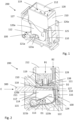
- Fig. 1 shows a connection terminal 200 or a part of a connection terminal 200 with a housing 210 in which a connection arrangement 100 is arranged.
- the housing 210 is made of an insulating material, in particular a plastic material.
- the connection arrangement 100 is arranged in an interior of the housing 210.
- connection arrangement 100 has a current bar 110 which, as shown for example in Fig. 2 can be seen, has a clamping section 111 against which a conductor 300 to be connected can be clamped and thus connected.
- connection arrangement 100 has a clamping spring 112, wherein the conductor 300 to be connected can be clamped in an electrically conductive manner against the current bar 110 or against the clamping section 111 of the current bar 110 by means of the clamping spring 112, as for example in Fig. 4 shown.
- the clamping spring 112 is designed as a leg spring.
- the clamping spring 112 has a holding leg 113 and a clamping leg 114.
- the holding leg 113 and the clamping leg 114 are connected to one another via an arcuate section 115.
- the holding leg 113 is arranged in a fixed position in the housing 210.
- the clamping leg 114 is pivotable relative to the holding leg 113, so that depending on the position of the clamping leg 114, the clamping spring 112 can be moved into an open position, as is the case, for example, in Fig. 1 and 2 shown, and in a clamping position, as for example in Fig. 3 and 4 shown, can be transferred and positioned.
- the clamping spring 112 also has a locking leg 116, so that the clamping spring 112 has three legs 113, 114, 116.
- the locking leg 116 is connected to the holding leg 113, so that the holding leg 113 is arranged between the clamping leg 114 and the locking leg 116.
- the locking leg 116 extends essentially at a right angle away from the holding leg 113.
- the locking leg 116 is designed to be so long that, at least in the open position of the clamping spring 112, it projects beyond the clamping leg 114 starting from the holding leg 113.
- the locking leg 116 serves to help hold the clamping spring 112 in the open position.
- the locking leg 116 extends from the holding leg 113 in the direction of the conductor connection space 117 or into the conductor connection space 117 which is formed between the current bar 110 or the clamping section 111 of the current bar 110 and the clamping spring 112, wherein the conductor 300 to be connected is introduced into this conductor connection space 117 in order to connect the conductor 300 and to clamp it against the clamping section 111 of the current bar 110.
- the locking leg 116 is designed to be so long that it delimits the conductor connection space 117 in the conductor insertion direction E.
- the conductor 300 strikes against the locking leg 116, whereby the locking leg 116 can be deflected or pivoted in the conductor insertion direction E.
- the locking leg 116 has a pressure surface 118 pointing in the direction of the conductor connection space 117, against which the conductor 300 can strike when inserted into the conductor connection space 117. So that the locking leg 116 can be deflected, the locking leg 116 is connected to the holding leg 113 in a spring-elastic manner.
- connection arrangement 100 further has a first actuating element 119.
- the first actuating element 119 is guided purely linearly in the housing 210.
- the first actuating element 119 is moved in the first actuating direction B1, in which the first actuating element 119 is moved in the direction of the clamping spring 112.
- the first actuating element 119 interacts with the clamping leg 114 of the clamping spring 112 in that the first actuating element 119 applies a force to the clamping leg 114 in the first actuating direction B1, so that it is pivoted in the direction of the holding leg 113 in order to release the conductor connection space 117.
- the first actuating element 119 has a U-shaped cross-section in the embodiment shown here.
- the first actuating element 119 has two actuating arms 120a, 120b extending parallel to one another. A free space is formed between the two actuating arms 120a, 120b through which the conductor 300 to be connected can be guided in order to be clamped against the clamping section 111 of the current bar 110.
- the two actuating arms 120a, 120b are designed to be long enough that they laterally delimit the conductor connection space 117 and can thus form a lateral guide for the conductor 300 to be connected.
- An actuating surface 121a, 121b is formed on the edge surfaces of the actuating arms 120a, 120b pointing in the direction of the clamping spring 114, which interact with the clamping spring 112 to actuate the clamping spring 112. With its two actuating surfaces 121a, 121b, the first actuating element 119 rests on the clamping leg 114 of the clamping spring 112 when it is transferred from the clamping position to the open position.
- the clamping leg 114 has a clamping tab 122 and two side tabs 123a, 123b arranged to the side of the clamping tab 122.
- the clamping tab 122 has a clamping edge 124 at its free end, by means of which the conductor 300 to be connected is clamped against the current bar 110 or against the clamping section 111 of the current bar 110.
- the clamping tab 122 is arranged between the two side tabs 123a, 123b.
- the clamping tab 122 is longer than the two side tabs 123a, 123b, so that the clamping tab 122 extends beyond the two side tabs 123a, 123b.
- the two side tabs 123a, 123b each have an arcuate shape.
- the two side tabs 123a, 123b can thus each form a sliding skid, which can slide along the actuating surfaces 121a, 121b when interacting with the first actuating element 119.
- the first actuating element 119 is thus in direct contact with the two side tabs 123a, 123b of the clamping spring 112 for actuating the clamping spring 112, whereas the clamping tab 122 has no direct contact with the first actuating element 119.
- the clamping tab 122 is arranged in the free space formed between the two actuating arms 120a, 120b.
- Fig. 1 and 2 show the clamping spring 112 in the open position, in which the conductor connection space 117 is released so that a conductor 300 to be connected can be inserted into it and also led out again.
- the clamping spring 112 and the first actuating element 119 are braced together so that the clamping spring 112 and the first actuating element 119 form a closed force system in which the first actuating element 119 is held in position by the clamping spring 112 without additional aids and the clamping spring 112 is in turn held in position by the first actuating element 119.
- the clamping of the first actuating element 119 with the clamping spring 112 is achieved by the clamping spring 112 applying two opposing pressure forces D1, D2 to the first actuating element 119 in the open position. These two opposing pressure forces D1, D2 allow the first actuating element 119 and thus also the clamping spring 112 to be held in a stable, stationary position in the open position of the clamping spring 112.
- the first pressure force D1 acts on the first actuating element 119 in the opposite direction to the first actuating direction B1.
- the first pressure force D1 is applied to the first actuating element 119 by the clamping leg 114, in particular by the side tabs 123a, 123b of the clamping leg 114.
- the side tabs 123a, 123b press onto the actuating surfaces 121a, 121b of the first actuating element 119 with the first pressure force D1 applied by the spring action of the clamping leg 114.
- the second pressure force D2 acts on the first actuating element 119 in the first actuating direction B1.
- the second pressure force D2 is applied to the first actuating element 119 by the locking leg 116 of the clamping spring 112.
- the locking leg 116 is held with its free end 125 on the first actuating element 119, in particular on the two actuating arms 120a, 120b of the first actuating element 119, in particular locked on the first actuating element 119.
- the free end 125 of the locking leg 116 has a T-shape in that the free end 125 has two holding arms 126a, 126b projecting outwards at the sides. In the open position, the locking leg 116 is held with its first holding arm 126a on the first actuating arm 120a and with its second holding arm 126b on the second actuating arm 120b.
- a holding contour 127 is formed on each of the two actuating arms 120a, 120b.
- the holding contour 127 is formed at a distance from the actuating surfaces 121a, 121b on the first actuating element 119.
- the two holding arms 126a, 126b of the locking leg 116 rest against the holding contour 127 of the actuating arms 120a, 120b in order to hold the locking leg 116 in a fixed position.
- a conductor 300 to be connected is inserted into the conductor connection space 117 via the conductor insertion opening 211 of the housing 210 in the conductor insertion direction E, the conductor 300 strikes the pressure surface 118 of the locking leg 116 of the clamping spring 112, which is arranged in alignment with the conductor insertion opening 211, as shown in Fig. 2 can be seen.
- the locking leg 116 can be pivoted in the conductor insertion direction E, so that the locking leg 116 can come out of engagement with the holding contour 127 of the first actuating element 119.
- the connection arrangement 100 has a second actuating element 128.
- This second actuating element 128 enables the clamping spring 112 to be released from its open position in order to be transferred to the clamping position.
- the second actuating element 128 cooperates with the locking leg 116, in particular with the holding arms 126a, 126b of the locking leg 116.
- the second actuating element 128 therefore does not cooperate with the clamping leg 114 of the clamping spring 112.
- the first actuating element 119 and the second actuating element 128 thus interact with the clamping spring 112 at different areas of the clamping spring 112.
- the second actuating element 128 can be actuated independently of the first actuating element 119.
- the second actuating element 128 can be guided along a second actuating direction B2 in order to release the clamping spring 112 from the open position.
- the second actuating direction B2 extends parallel to the first actuating direction B1, so that the second actuating element 128 is guided in a direction parallel to the first actuating element 119.
- the second actuating element 128 is thus guided linearly in the same way as the first actuating element 119.
- the second actuating element 128 is arranged directly adjacent to the first actuating element 119.
- the housing 210 has a guide shaft 212, wherein the first actuating element 119 and the second actuating element 128 are arranged and guided in this guide shaft 212.
- the first actuating element 119 has a groove 129 on its outer peripheral surface, into which a web 130 formed on the second actuating element 128 engages. The two actuating elements 119, 128 engage with one another in a form-fitting manner via the groove 129 and the web 130.
- the form-fitting engagement and the form-fitting guidance of the two actuating elements 119, 128 prevent the actuating elements 119, 128 from tilting or jamming relative to one another. It is also possible for the groove 129 to be formed on the second actuating element 128 and the web 130 to be formed on the first actuating element 119. It is also possible to provide two or more grooves 129 and two or more webs 130.
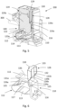
- the second actuating element 128 has a first actuating finger 131a and a second actuating finger 132b, as in particular also in Fig. 6 can be recognized.
- Fig. 6 shows the Fig. 1 to 5 shown connection arrangement 100 only with the current bar 110, the clamping spring 112, and the second actuating element 128.
- the two actuating fingers 131a, 131b cooperate with the two holding arms 126 of the locking leg 126 of the clamping spring 112 in order to release the clamping spring 112 from its open position.
- the two actuating fingers 131a, 131b extend parallel to one another.
- the two actuating fingers 131a, 131b are formed on a base body 132 of the second actuating element 128.
- the two actuating fingers 131a, 131b can be formed in one piece with the base body 132.
- the entire actuating element 128 can then be made of a Insulating material, in particular a plastic material.
- the base body 132 has an actuating surface 133, via which the second actuating element 128 can be actuated by a user.
- the two actuating fingers 131a, 131b each have a sliding surface 134a, 134b over which the actuating fingers 131a, 131b can slide along the holding arms 126a, 126b in order to be able to push the holding arms 126a, 126b and thus the locking leg 116 out of the locking connection with the first actuating element 119 and thus release them, so that the locking leg 116 can be pivoted in the conductor insertion direction E via the second actuating element 128.
- the two sliding surfaces 134a, 134b are each designed in the form of inclined surfaces. Due to the sliding surfaces 134a, 134b designed as inclined surfaces, the actuating fingers 131a, 131b taper towards their free end.
- the two actuating fingers 131a, 131b are designed symmetrically to each other, so that by means of the two actuating fingers 131a, 131b a simultaneous actuation of the two holding arms 126a, 126b of the locking leg 116 is possible.
- the two holding arms 126a, 126b of the locking leg 116 are designed to be so long that they laterally overlap the current bar 110 or the clamping section 111 of the current bar 110.
- the clamping section 111 is surrounded in a U-shape by the locking leg 116, in particular by the free end 125 of the locking leg 116 with the two holding arms 126a, 126b.
- the two holding arms 126a, 126b each have an L-shape here, so that the two holding arms 126a, 126b extend in the direction of the second actuating element 128.
- the two holding arms 126a, 126b are guided out of the area of the conductor connection space 117 in the direction of the second actuating element 128.
- An interaction of the second actuating element 128 with the two holding arms 126a, 126b and thus of the locking leg 116 takes place here outside the conductor connection space 117.
- the clamping section 111 of the current bar 110 has a clamping surface 135 which points in the direction of the conductor connection space 117 and against which the clamping of the conductor 300 to be connected takes place.
- the two holding arms 126a, 126b extend beyond this clamping surface 135 to above an upper surface 136 of the clamping section 111, which is opposite the clamping surface 135.
- the actuation of the holding arms 126a, 126b and thus of the locking leg 116 by means of the second actuating element 128 takes place above the upper surface 136.
- Fig. 7 shows another possible embodiment, whereby the two actuating fingers 131a, 132a are longer than in the Fig. 6
- the design shown in Fig. 7 In the embodiment shown, when the locking leg 116 is actuated by means of the second actuating element 128, the two actuating fingers 131a, 132 of the second actuating element 128 can be guided laterally past the clamping section 111 of the current bar 110 in order to cooperate with the holding arms 126a, 126b of the locking leg 116.
- the two holding arms 126a, 126b of the locking leg 116 are for this purpose in contrast to the Fig. 6 shown design is much shorter.
- the two actuating fingers 131a, 131b are of equal length, so that both actuating fingers 131a, 131b are guided laterally past the clamping section 111 of the current bar 110 to actuate the locking leg 116.
- the second actuating element 128 here encompasses the clamping section 111 of the current bar 110 in a U-shape.
- the two actuating fingers 131a, 131b are spaced apart from one another so far that, in particular when the clamping spring 112 or the locking leg 116 of the clamping spring 112 is actuated, the two actuating fingers 131a, 131b are guided past the clamping section 111 of the current bar 110 on two opposite side surfaces of the clamping section 111 of the current bar 110.
- the actuation of the holding arms 126a, 126b and thus of the locking leg 116 takes place here in the area of the conductor connection space 117.
- the two actuating fingers 131a, 131b can act on the holding arms 126a, 126b in order to release them from the locking connection with the first actuating element 119.
- Two opposing recesses 137a, 137b are formed on the clamping section 111 of the current bar 110, in each of which one of the two actuating fingers 131a, 131b is guided as it passes the clamping section 111 of the current bar 110.
- the actuating fingers 131a, 131b can thus penetrate directly through the clamping section 111 of the current bar 110, as shown in Fig. 7 shown.
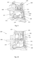
- Fig. 8 to 10 show a terminal 200 with a connection arrangement 100 as shown in Fig. 7
- the clamping spring 112 and the first actuating element 119 correspond to the Fig. 1 to 6 shown design.
- Fig. 8 and 9 show the clamping spring 112 in the open position and
- Fig. 10 show the clamping spring 112 in the clamping position with connected conductor 300.
- the conductor 300 is used in both embodiments of the Fig. 1 to 10 transversely to the actuating direction B1 and B2 of the two actuating elements 119, 128 into the conductor connection space 117 and thus into the connection arrangement 100 or into the connection terminal 200.
- the first actuating element 119 is spring-loaded by means of a spring element 138 in the open position of the clamping spring 112.
- the spring element 138 can cause the first actuating element 119 to be returned to a defined, reproducible position, in particular the starting position, when the clamping spring 112 is transferred from the open position to the clamping position.
- the first actuating element 119 can be spring-loaded, for example, against the current bar 110 or against the clamping section 111 of the current bar 110, as shown in the figures.
- the spring element 138 is designed here in the form of a spiral spring.
Landscapes
- Connections Arranged To Contact A Plurality Of Conductors (AREA)
- Clamps And Clips (AREA)
- Details Of Connecting Devices For Male And Female Coupling (AREA)
Claims (11)
- Ensemble de raccordement (100) destiné au raccordement d'un conducteur électrique (300), ledit ensemble comprenantune barre de courant (110),un ressort de serrage (112) qui peut être transféré dans une position de serrage et dans une position ouverte, le conducteur électrique (300) à raccorder étant serré contre une portion de serrage (111) de la barre de courant (110) lorsque le ressort de serrage (112) est dans la position de serrage,un premier élément d'actionnement (119) qui peut être guidé suivant une première direction d'actionnement (B1) et qui permet de transférer le ressort de serrage (112) de la position de serrage à la position ouverte, etun deuxième élément d'actionnement (128) qui peut être guidé suivant une deuxième direction d'actionnement (B2) et qui permet de dégager le ressort de serrage (112) de la position ouverte, le ressort de serrage (112) comportant une branche de retenue (113) et une branche de serrage (114) destinée à serrer le conducteur (300) à raccorder contre la portion de serrage (111) de la barre de courant (110) lorsque le ressort de serrage (112) est dans la position de serrage et une branche d'encliquetage (116) qui est maintenue dans une position fixe lorsque le ressort de serrage (112) est dans la position ouverte, la branche de serrage (112) pouvant être actionnée au moyen du premier élément d'actionnement (119) et la branche d'encliquetage (116) pouvant être actionnée au moyen du deuxième élément d'actionnement (128),caractérisé en ce que le premier élément d'actionnement (119) présente un contour de retenue (127) contre lequel la branche d'encliquetage (116) est maintenue lorsque le ressort de serrage (112) est dans la position ouverte, la branche d'encliquetage (116) comportant une extrémité libre (125) sur laquelle est formé au moins un bras de retenue (126a, 126b) qui permet de maintenir la branche d'encliquetage (116) contre le contour de retenue (127) du premier élément d'actionnement (119) lorsque le ressort de serrage (112) est dans la position ouverte, le deuxième élément d'actionnement (128) coopérant avec l'au moins un bras de retenue (126a, 126b) pendant le transfert de la position de serrage à la position ouverte.
- Ensemble de raccordement (100) selon la revendication 1, caractérisé en ce que le premier élément d'actionnement (119) et le deuxième élément d'actionnement (128) sont disposés l'un par rapport à l'autre de manière à ce que la première direction d'actionnement (B1) du premier élément d'actionnement (119) soit parallèle à la deuxième direction d'actionnement (B2) du deuxième élément d'actionnement (128) .
- Ensemble de raccordement (100) selon la revendication 1 ou 2, caractérisé en ce que le premier élément d'actionnement (128) comporte un premier bras d'actionnement (120a) et un deuxième bras d'actionnement (120b) disposé à distance du premier bras d'actionnement (120a), le contour de retenue (126) étant formé sur le premier bras d'actionnement (120a) et sur le deuxième bras d'actionnement (120b).
- Ensemble de raccordement (100) selon l'une des revendications 1 à 3, caractérisé en ce que le deuxième élément d'actionnement (128) comporte au moins un doigt d'actionnement (131a, 131b) qui, lorsque le ressort de serrage (112) est transféré de la position ouverte à la position de serrage, coopère avec au moins un bras de retenue (126a, 126b).
- Ensemble de raccordement (100) selon la revendication 4, caractérisé en ce que l'au moins un doigt d'actionnement (131a, 131b) est conçu de manière à avoir une longueur telle que, lorsque le deuxième élément d'actionnement (128) est guidé suivant la deuxième direction d'actionnement (B2), l'au moins un doigt d'actionnement (131a, 131b) dépasse latéralement la portion de serrage (111) de la barre de courant (110) afin d'actionner la branche de verrouillage (116) .
- Ensemble de raccordement (100) selon la revendication 5, caractérisé en ce qu'au moins un évidement (137a, 137b) est formé sur la portion de serrage (111) de la barre de courant (110), évidement dans lequel au moins un doigt d'actionnement (131a, 131b) est amené lors du dépassement latéral.
- Ensemble de raccordement (100) selon la revendication 4, caractérisé en ce que l'au moins un bras de retenue (126a, 126b) est conçu pour avoir une longueur telle que l'au moins un bras de retenue (126a, 126b) chevauche latéralement la portion de serrage (111) de la barre de courant (110).
- Ensemble de raccordement (100) selon l'une des revendications 1 à 7, caractérisé en ce que le premier élément d'actionnement (119) comporte un élément à ressort (138) qui permet de précontraindre élastiquement le premier élément d'actionnement (119) dans la position ouverte.
- Ensemble de raccordement (100) selon l'une des revendications 1 à 8, caractérisé en ce que la première direction d'actionnement (B1) du premier élément d'actionnement (119) et/ou la deuxième direction d'actionnement (B2) du deuxième élément d'actionnement (128) sont conçues pour être transversales à une direction d'insertion (E) du conducteur (300) à raccorder dans un espace de raccordement de conducteur (117) formé entre la portion de serrage (111) de la barre de courant (100) et le ressort de serrage (112).
- Borne de raccordement (200), notamment borne série, comprenant un boîtier (210) et au moins un ensemble de raccordement (100) selon l'une des revendications 1 à 9 disposé dans le boîtier (210).
- Appareil électronique comprenant au moins un ensemble de raccordement (100) selon l'une des revendications 1 à 9 et/ou au moins une borne de raccordement (200) selon la revendication 10.
Applications Claiming Priority (1)
| Application Number | Priority Date | Filing Date | Title |
|---|---|---|---|
| DE102021111072.6A DE102021111072A1 (de) | 2021-04-29 | 2021-04-29 | Anschlussanordnung, Anschlussklemme und elektronisches Gerät |
Publications (2)
| Publication Number | Publication Date |
|---|---|
| EP4084226A1 EP4084226A1 (fr) | 2022-11-02 |
| EP4084226B1 true EP4084226B1 (fr) | 2024-11-13 |
Family
ID=81328185
Family Applications (1)
| Application Number | Title | Priority Date | Filing Date |
|---|---|---|---|
| EP22168713.0A Active EP4084226B1 (fr) | 2021-04-29 | 2022-04-19 | Agencement de borne, borne de connexion et appareil électronique |
Country Status (4)
| Country | Link |
|---|---|
| EP (1) | EP4084226B1 (fr) |
| CN (1) | CN115275667B (fr) |
| DE (1) | DE102021111072A1 (fr) |
| ES (1) | ES3002960T3 (fr) |
Families Citing this family (4)
| Publication number | Priority date | Publication date | Assignee | Title |
|---|---|---|---|---|
| LU503120B1 (de) * | 2022-11-30 | 2024-05-30 | Phoenix Contact Gmbh & Co | Anschlussklemme zum Anschließen einer elektrischen Leitung |
| LU503121B1 (de) * | 2022-11-30 | 2024-05-30 | Phoenix Contact Gmbh & Co | Anschlussklemme zum Anschließen einer elektrischen Leitung |
| CN116487906A (zh) * | 2023-05-24 | 2023-07-25 | 町洋机电(中国)有限公司 | 便捷接线的端子台结构 |
| LU507360B1 (de) * | 2024-05-28 | 2025-11-28 | Phoenix Contact Gmbh & Co | Anschlussklemme zum Anschließen einer elektrischen Leitung |
Family Cites Families (12)
| Publication number | Priority date | Publication date | Assignee | Title |
|---|---|---|---|---|
| DE3044133C2 (de) * | 1980-11-24 | 1982-12-16 | Siemens AG, 1000 Berlin und 8000 München | Schraubenlose Klemme |
| JP3301131B2 (ja) * | 1992-11-30 | 2002-07-15 | 松下電工株式会社 | 端子装置 |
| EP0780923B1 (fr) * | 1995-12-22 | 2003-01-22 | HAGER ELECTRO GmbH | Serrage pour relier une extrémité d'une âme de conducteur avec un contact |
| JPH11273765A (ja) * | 1998-03-25 | 1999-10-08 | Suncall Corp | 端子短絡用板ばね |
| JP2901590B1 (ja) * | 1998-04-30 | 1999-06-07 | 日東工業株式会社 | 端子装置 |
| DE20300266U1 (de) * | 2003-01-08 | 2004-05-19 | Bals Elektrotechnik Gmbh & Co. Kg | Leiteranschlussklemme, insbesondere für Steckverbinder |
| DE202006009460U1 (de) * | 2005-10-29 | 2007-03-15 | Weidmüller Interface GmbH & Co. KG | Anschlussvorrichtung für Leiter |
| CN102969599A (zh) * | 2012-11-14 | 2013-03-13 | 中航光电科技股份有限公司 | 一种弹簧片锁线机构及使用该机构的快速压线电连接器 |
| DE202016102959U1 (de) * | 2016-06-02 | 2017-09-06 | Weidmüller Interface GmbH & Co. KG | Federkraftklemme für Leiter |
| DE102016115601A1 (de) * | 2016-08-23 | 2018-03-01 | Wago Verwaltungsgesellschaft Mbh | Federkraftklemmanschluss |
| DE202016105826U1 (de) * | 2016-10-18 | 2018-01-19 | Wago Verwaltungsgesellschaft Mbh | Leiteranschlussklemme mit wenigstens einem Federkraftklemmanschluss |
| DE202018102218U1 (de) * | 2018-04-20 | 2019-07-23 | Phoenix Contact Gmbh & Co. Kg | Elektrische Anschlussklemme |
-
2021
- 2021-04-29 DE DE102021111072.6A patent/DE102021111072A1/de active Pending
-
2022
- 2022-04-19 ES ES22168713T patent/ES3002960T3/es active Active
- 2022-04-19 EP EP22168713.0A patent/EP4084226B1/fr active Active
- 2022-04-28 CN CN202210460181.0A patent/CN115275667B/zh active Active
Also Published As
| Publication number | Publication date |
|---|---|
| CN115275667A (zh) | 2022-11-01 |
| ES3002960T3 (en) | 2025-03-10 |
| EP4084226A1 (fr) | 2022-11-02 |
| CN115275667B (zh) | 2026-03-31 |
| DE102021111072A1 (de) | 2022-11-03 |
Similar Documents
| Publication | Publication Date | Title |
|---|---|---|
| EP4084226B1 (fr) | Agencement de borne, borne de connexion et appareil électronique | |
| EP3298659B1 (fr) | Borne de connexion de conducteur | |
| EP3477775B1 (fr) | Borne de connexion de conducteur et insert de contact | |
| DE102020104140A1 (de) | Anschlussanordnung | |
| EP1251590B1 (fr) | Borne électrique | |
| DE102021117396A1 (de) | Anschlussanordnung, Anschlussklemme und elektronisches Gerät | |
| DE19835459C2 (de) | Anschlußklemme für elektrische Leiter | |
| DE4433983A1 (de) | Anschlußklemme für elektrische Installationen | |
| EP3504756B1 (fr) | Borne de connexion | |
| EP1818964B1 (fr) | Barrette de fusibles avec contacts de sortie latéraux et module adaptateur latéral | |
| DE102020104138B4 (de) | Anschlussanordnung | |
| EP4062494B1 (fr) | Dispositif de connexion, pince de connexion et dispositif électronique | |
| EP1217692A2 (fr) | Borne de connection pour conducteurs électriques | |
| DE3830442A1 (de) | Klemmvorrichtung zum schraubenlosen anschluss mindestens eines elektrischen leiterdrahts an ein geraet | |
| EP1753087B1 (fr) | Borne électrique | |
| DE102021104504A1 (de) | Anschlussanordnung, Anschlussklemme und elektronisches Gerät | |
| EP1523065B1 (fr) | Borne électrique | |
| DE2511385B2 (de) | Elektrische anschlussklemme | |
| EP1086513B1 (fr) | Borne de connexion | |
| WO2000070714A1 (fr) | Borne de raccordement sans vis | |
| DE2706988A1 (de) | Schraubenlose anschlussklemme zur stromuebertragung von elektrischen leitern | |
| DE202015104145U1 (de) | Klemme | |
| EP0336251B1 (fr) | Borne à vis | |
| EP4047754A1 (fr) | Ressort de serrage, agencement de connexion et borne | |
| EP4060817A1 (fr) | Système de compensation de potentiel et système modulaire |
Legal Events
| Date | Code | Title | Description |
|---|---|---|---|
| PUAI | Public reference made under article 153(3) epc to a published international application that has entered the european phase |
Free format text: ORIGINAL CODE: 0009012 |
|
| STAA | Information on the status of an ep patent application or granted ep patent |
Free format text: STATUS: THE APPLICATION HAS BEEN PUBLISHED |
|
| AK | Designated contracting states |
Kind code of ref document: A1 Designated state(s): AL AT BE BG CH CY CZ DE DK EE ES FI FR GB GR HR HU IE IS IT LI LT LU LV MC MK MT NL NO PL PT RO RS SE SI SK SM TR |
|
| STAA | Information on the status of an ep patent application or granted ep patent |
Free format text: STATUS: REQUEST FOR EXAMINATION WAS MADE |
|
| 17P | Request for examination filed |
Effective date: 20230302 |
|
| RBV | Designated contracting states (corrected) |
Designated state(s): AL AT BE BG CH CY CZ DE DK EE ES FI FR GB GR HR HU IE IS IT LI LT LU LV MC MK MT NL NO PL PT RO RS SE SI SK SM TR |
|
| P01 | Opt-out of the competence of the unified patent court (upc) registered |
Effective date: 20230512 |
|
| GRAP | Despatch of communication of intention to grant a patent |
Free format text: ORIGINAL CODE: EPIDOSNIGR1 |
|
| GRAP | Despatch of communication of intention to grant a patent |
Free format text: ORIGINAL CODE: EPIDOSNIGR1 |
|
| STAA | Information on the status of an ep patent application or granted ep patent |
Free format text: STATUS: GRANT OF PATENT IS INTENDED |
|
| INTG | Intention to grant announced |
Effective date: 20240614 |
|
| RIC1 | Information provided on ipc code assigned before grant |
Ipc: H01R 13/193 20060101ALI20240531BHEP Ipc: H01R 4/48 20060101AFI20240531BHEP |
|
| GRAS | Grant fee paid |
Free format text: ORIGINAL CODE: EPIDOSNIGR3 |
|
| GRAA | (expected) grant |
Free format text: ORIGINAL CODE: 0009210 |
|
| STAA | Information on the status of an ep patent application or granted ep patent |
Free format text: STATUS: THE PATENT HAS BEEN GRANTED |
|
| AK | Designated contracting states |
Kind code of ref document: B1 Designated state(s): AL AT BE BG CH CY CZ DE DK EE ES FI FR GB GR HR HU IE IS IT LI LT LU LV MC MK MT NL NO PL PT RO RS SE SI SK SM TR |
|
| REG | Reference to a national code |
Ref country code: GB Ref legal event code: FG4D Free format text: NOT ENGLISH |
|
| REG | Reference to a national code |
Ref country code: CH Ref legal event code: EP |
|
| REG | Reference to a national code |
Ref country code: DE Ref legal event code: R096 Ref document number: 502022002107 Country of ref document: DE |
|
| REG | Reference to a national code |
Ref country code: IE Ref legal event code: FG4D Free format text: LANGUAGE OF EP DOCUMENT: GERMAN |
|
| REG | Reference to a national code |
Ref country code: LT Ref legal event code: MG9D Ref country code: ES Ref legal event code: FG2A Ref document number: 3002960 Country of ref document: ES Kind code of ref document: T3 Effective date: 20250310 |
|
| REG | Reference to a national code |
Ref country code: NL Ref legal event code: MP Effective date: 20241113 |
|
| PG25 | Lapsed in a contracting state [announced via postgrant information from national office to epo] |
Ref country code: HR Free format text: LAPSE BECAUSE OF FAILURE TO SUBMIT A TRANSLATION OF THE DESCRIPTION OR TO PAY THE FEE WITHIN THE PRESCRIBED TIME-LIMIT Effective date: 20241113 Ref country code: IS Free format text: LAPSE BECAUSE OF FAILURE TO SUBMIT A TRANSLATION OF THE DESCRIPTION OR TO PAY THE FEE WITHIN THE PRESCRIBED TIME-LIMIT Effective date: 20250313 Ref country code: PT Free format text: LAPSE BECAUSE OF FAILURE TO SUBMIT A TRANSLATION OF THE DESCRIPTION OR TO PAY THE FEE WITHIN THE PRESCRIBED TIME-LIMIT Effective date: 20250313 |
|
| PG25 | Lapsed in a contracting state [announced via postgrant information from national office to epo] |
Ref country code: FI Free format text: LAPSE BECAUSE OF FAILURE TO SUBMIT A TRANSLATION OF THE DESCRIPTION OR TO PAY THE FEE WITHIN THE PRESCRIBED TIME-LIMIT Effective date: 20241113 Ref country code: NL Free format text: LAPSE BECAUSE OF FAILURE TO SUBMIT A TRANSLATION OF THE DESCRIPTION OR TO PAY THE FEE WITHIN THE PRESCRIBED TIME-LIMIT Effective date: 20241113 |
|
| PG25 | Lapsed in a contracting state [announced via postgrant information from national office to epo] |
Ref country code: BG Free format text: LAPSE BECAUSE OF FAILURE TO SUBMIT A TRANSLATION OF THE DESCRIPTION OR TO PAY THE FEE WITHIN THE PRESCRIBED TIME-LIMIT Effective date: 20241113 |
|
| PG25 | Lapsed in a contracting state [announced via postgrant information from national office to epo] |
Ref country code: NO Free format text: LAPSE BECAUSE OF FAILURE TO SUBMIT A TRANSLATION OF THE DESCRIPTION OR TO PAY THE FEE WITHIN THE PRESCRIBED TIME-LIMIT Effective date: 20250213 |
|
| PG25 | Lapsed in a contracting state [announced via postgrant information from national office to epo] |
Ref country code: GR Free format text: LAPSE BECAUSE OF FAILURE TO SUBMIT A TRANSLATION OF THE DESCRIPTION OR TO PAY THE FEE WITHIN THE PRESCRIBED TIME-LIMIT Effective date: 20250214 Ref country code: LV Free format text: LAPSE BECAUSE OF FAILURE TO SUBMIT A TRANSLATION OF THE DESCRIPTION OR TO PAY THE FEE WITHIN THE PRESCRIBED TIME-LIMIT Effective date: 20241113 |
|
| PG25 | Lapsed in a contracting state [announced via postgrant information from national office to epo] |
Ref country code: PL Free format text: LAPSE BECAUSE OF FAILURE TO SUBMIT A TRANSLATION OF THE DESCRIPTION OR TO PAY THE FEE WITHIN THE PRESCRIBED TIME-LIMIT Effective date: 20241113 |
|
| PG25 | Lapsed in a contracting state [announced via postgrant information from national office to epo] |
Ref country code: RS Free format text: LAPSE BECAUSE OF FAILURE TO SUBMIT A TRANSLATION OF THE DESCRIPTION OR TO PAY THE FEE WITHIN THE PRESCRIBED TIME-LIMIT Effective date: 20250213 |
|
| PG25 | Lapsed in a contracting state [announced via postgrant information from national office to epo] |
Ref country code: SM Free format text: LAPSE BECAUSE OF FAILURE TO SUBMIT A TRANSLATION OF THE DESCRIPTION OR TO PAY THE FEE WITHIN THE PRESCRIBED TIME-LIMIT Effective date: 20241113 |
|
| PGFP | Annual fee paid to national office [announced via postgrant information from national office to epo] |
Ref country code: DE Payment date: 20250626 Year of fee payment: 4 |
|
| PG25 | Lapsed in a contracting state [announced via postgrant information from national office to epo] |
Ref country code: DK Free format text: LAPSE BECAUSE OF FAILURE TO SUBMIT A TRANSLATION OF THE DESCRIPTION OR TO PAY THE FEE WITHIN THE PRESCRIBED TIME-LIMIT Effective date: 20241113 |
|
| PGFP | Annual fee paid to national office [announced via postgrant information from national office to epo] |
Ref country code: ES Payment date: 20250513 Year of fee payment: 4 |
|
| PGFP | Annual fee paid to national office [announced via postgrant information from national office to epo] |
Ref country code: IT Payment date: 20250430 Year of fee payment: 4 |
|
| PG25 | Lapsed in a contracting state [announced via postgrant information from national office to epo] |
Ref country code: EE Free format text: LAPSE BECAUSE OF FAILURE TO SUBMIT A TRANSLATION OF THE DESCRIPTION OR TO PAY THE FEE WITHIN THE PRESCRIBED TIME-LIMIT Effective date: 20241113 |
|
| PGFP | Annual fee paid to national office [announced via postgrant information from national office to epo] |
Ref country code: FR Payment date: 20250424 Year of fee payment: 4 |
|
| PG25 | Lapsed in a contracting state [announced via postgrant information from national office to epo] |
Ref country code: RO Free format text: LAPSE BECAUSE OF FAILURE TO SUBMIT A TRANSLATION OF THE DESCRIPTION OR TO PAY THE FEE WITHIN THE PRESCRIBED TIME-LIMIT Effective date: 20241113 |
|
| PGFP | Annual fee paid to national office [announced via postgrant information from national office to epo] |
Ref country code: AT Payment date: 20250721 Year of fee payment: 4 |
|
| PG25 | Lapsed in a contracting state [announced via postgrant information from national office to epo] |
Ref country code: SK Free format text: LAPSE BECAUSE OF FAILURE TO SUBMIT A TRANSLATION OF THE DESCRIPTION OR TO PAY THE FEE WITHIN THE PRESCRIBED TIME-LIMIT Effective date: 20241113 |
|
| PG25 | Lapsed in a contracting state [announced via postgrant information from national office to epo] |
Ref country code: CZ Free format text: LAPSE BECAUSE OF FAILURE TO SUBMIT A TRANSLATION OF THE DESCRIPTION OR TO PAY THE FEE WITHIN THE PRESCRIBED TIME-LIMIT Effective date: 20241113 |
|
| REG | Reference to a national code |
Ref country code: DE Ref legal event code: R097 Ref document number: 502022002107 Country of ref document: DE |
|
| PG25 | Lapsed in a contracting state [announced via postgrant information from national office to epo] |
Ref country code: SE Free format text: LAPSE BECAUSE OF FAILURE TO SUBMIT A TRANSLATION OF THE DESCRIPTION OR TO PAY THE FEE WITHIN THE PRESCRIBED TIME-LIMIT Effective date: 20241113 |
|
| PLBE | No opposition filed within time limit |
Free format text: ORIGINAL CODE: 0009261 |
|
| STAA | Information on the status of an ep patent application or granted ep patent |
Free format text: STATUS: NO OPPOSITION FILED WITHIN TIME LIMIT |
|
| 26N | No opposition filed |
Effective date: 20250814 |
|
| REG | Reference to a national code |
Ref country code: CH Ref legal event code: H13 Free format text: ST27 STATUS EVENT CODE: U-0-0-H10-H13 (AS PROVIDED BY THE NATIONAL OFFICE) Effective date: 20251125 |
|
| PG25 | Lapsed in a contracting state [announced via postgrant information from national office to epo] |
Ref country code: LU Free format text: LAPSE BECAUSE OF NON-PAYMENT OF DUE FEES Effective date: 20250419 |
|
| PG25 | Lapsed in a contracting state [announced via postgrant information from national office to epo] |
Ref country code: MC Free format text: LAPSE BECAUSE OF FAILURE TO SUBMIT A TRANSLATION OF THE DESCRIPTION OR TO PAY THE FEE WITHIN THE PRESCRIBED TIME-LIMIT Effective date: 20241113 |
|
| REG | Reference to a national code |
Ref country code: BE Ref legal event code: MM Effective date: 20250430 |
|
| PG25 | Lapsed in a contracting state [announced via postgrant information from national office to epo] |
Ref country code: BE Free format text: LAPSE BECAUSE OF NON-PAYMENT OF DUE FEES Effective date: 20250430 |
|
| PG25 | Lapsed in a contracting state [announced via postgrant information from national office to epo] |
Ref country code: CH Free format text: LAPSE BECAUSE OF NON-PAYMENT OF DUE FEES Effective date: 20250430 |
|
| PG25 | Lapsed in a contracting state [announced via postgrant information from national office to epo] |
Ref country code: IE Free format text: LAPSE BECAUSE OF NON-PAYMENT OF DUE FEES Effective date: 20250419 |