EP4084251A1 - Schaltung zur verhinderung des umgekehrten anschlusses einer stromquelle, stromverteilungsvorrichtung und stromversorgungs- und verteilungssystem - Google Patents
Schaltung zur verhinderung des umgekehrten anschlusses einer stromquelle, stromverteilungsvorrichtung und stromversorgungs- und verteilungssystem Download PDFInfo
- Publication number
- EP4084251A1 EP4084251A1 EP21890605.5A EP21890605A EP4084251A1 EP 4084251 A1 EP4084251 A1 EP 4084251A1 EP 21890605 A EP21890605 A EP 21890605A EP 4084251 A1 EP4084251 A1 EP 4084251A1
- Authority
- EP
- European Patent Office
- Prior art keywords
- circuit breaker
- diode
- actuation unit
- connection preventing
- power connection
- Prior art date
- Legal status (The legal status is an assumption and is not a legal conclusion. Google has not performed a legal analysis and makes no representation as to the accuracy of the status listed.)
- Granted
Links
Images




Classifications
-
- H—ELECTRICITY
- H02—GENERATION; CONVERSION OR DISTRIBUTION OF ELECTRIC POWER
- H02H—EMERGENCY PROTECTIVE CIRCUIT ARRANGEMENTS
- H02H11/00—Emergency protective circuit arrangements for preventing the switching-on in case an undesired electric working condition might result
- H02H11/002—Emergency protective circuit arrangements for preventing the switching-on in case an undesired electric working condition might result in case of inverted polarity or connection; with switching for obtaining correct connection
-
- Y—GENERAL TAGGING OF NEW TECHNOLOGICAL DEVELOPMENTS; GENERAL TAGGING OF CROSS-SECTIONAL TECHNOLOGIES SPANNING OVER SEVERAL SECTIONS OF THE IPC; TECHNICAL SUBJECTS COVERED BY FORMER USPC CROSS-REFERENCE ART COLLECTIONS [XRACs] AND DIGESTS
- Y02—TECHNOLOGIES OR APPLICATIONS FOR MITIGATION OR ADAPTATION AGAINST CLIMATE CHANGE
- Y02B—CLIMATE CHANGE MITIGATION TECHNOLOGIES RELATED TO BUILDINGS, e.g. HOUSING, HOUSE APPLIANCES OR RELATED END-USER APPLICATIONS
- Y02B70/00—Technologies for an efficient end-user side electric power management and consumption
- Y02B70/30—Systems integrating technologies related to power network operation and communication or information technologies for improving the carbon footprint of the management of residential or tertiary loads, i.e. smart grids as climate change mitigation technology in the buildings sector, including also the last stages of power distribution and the control, monitoring or operating management systems at local level
-
- Y—GENERAL TAGGING OF NEW TECHNOLOGICAL DEVELOPMENTS; GENERAL TAGGING OF CROSS-SECTIONAL TECHNOLOGIES SPANNING OVER SEVERAL SECTIONS OF THE IPC; TECHNICAL SUBJECTS COVERED BY FORMER USPC CROSS-REFERENCE ART COLLECTIONS [XRACs] AND DIGESTS
- Y04—INFORMATION OR COMMUNICATION TECHNOLOGIES HAVING AN IMPACT ON OTHER TECHNOLOGY AREAS
- Y04S—SYSTEMS INTEGRATING TECHNOLOGIES RELATED TO POWER NETWORK OPERATION, COMMUNICATION OR INFORMATION TECHNOLOGIES FOR IMPROVING THE ELECTRICAL POWER GENERATION, TRANSMISSION, DISTRIBUTION, MANAGEMENT OR USAGE, i.e. SMART GRIDS
- Y04S20/00—Management or operation of end-user stationary applications or the last stages of power distribution; Controlling, monitoring or operating thereof
- Y04S20/20—End-user application control systems
Definitions
- This application relates to the field of circuit technologies, and in particular, to a reverse power connection preventing circuit, a power distribution apparatus, and a power supply and distribution system.
- a storage battery is an important component of a power supply and distribution system.
- the storage battery provides a safe, stable, and reliable power guarantee for a communications device when alternating current power supply is interrupted or fails for short time, thereby ensuring normal operation of the communications device.
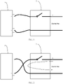
- a storage battery 1 is usually connected to a system bus by using a circuit breaker 2. Due to manual wiring, an operational error, shown in FIG. 2 , that cables of the storage battery 1 are reversely connected is unavoidable, and device damage and a safety accident that are caused by the reverse connection of the storage battery 1 sometimes occur.
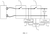
- a magnetic contactor 3 is connected in series behind the circuit breaker 2, and voltage sampling circuits 41 and 42 are respectively disposed at two ends of the magnetic contactor 3. Only when determining that voltages detected by the two voltage sampling circuits 41 and 42 have same polarity, a control unit 5 sends an instruction for closing the magnetic contactor 3.
- the voltage sampling circuit 41 at one end that is of the magnetic contactor 3 and that is close to the circuit breaker 2 samples a voltage of the reversely connected storage battery 1
- the voltage sampling circuit 42 at the other end of the magnetic contactor 3 samples a voltage on the system bus. Therefore, the voltages of the two ends are inconsistent, and the magnetic contactor 3 is not closed, thereby preventing a short-circuit failure.
- adding the magnetic contactor and the voltage sampling circuits causes higher costs, a larger volume, a higher loss, and a higher heat dissipating requirement.
- This application provides a reverse power connection preventing circuit, a power distribution apparatus, and a power supply and distribution system, to avoid a loss caused by a reverse connection between a power supply and a circuit breaker.
- this application provides a reverse power connection preventing circuit, including a diode and an actuation unit that are connected in series.
- the diode and the actuation unit that are connected in series are configured to connect a positive input terminal and a negative input terminal of the circuit breaker.
- a positive electrode of the diode points to the negative wiring terminal of the circuit breaker, and a negative electrode of the diode points to the positive input terminal of the circuit breaker.
- the actuation unit When the power supply is reversely connected to the circuit breaker, the diode is conducted, and the actuation unit is configured to prevent closing of the circuit breaker, or the actuation unit is configured to perform an alarm prompt, to perform an early warning to prompt an operator not to close the circuit breaker.
- the actuation unit may be alternatively configured to: when the diode is conducted, prevent closing of the circuit breaker and also perform an alarm prompt. Therefore, a short-circuit accident caused by the reverse connection of the power supply is completely prevented.
- the reverse power connection preventing circuit also ensures safety of on-site construction, thereby fundamentally avoiding a safety risk caused by the reverse connection.
- the reverse power connection preventing circuit provided in this application is simple in structure, so that a volume and costs can be reduced compared with the conventional technology.
- the reverse power connection preventing circuit provided in this application may further include a current limiting resistor. After being connected in series to the diode and the actuation unit, the current limiting resistor is configured to connect the positive input terminal and the negative input terminal of the circuit breaker. The current limiting resistor can limit a current flowing through the diode and the actuation unit, thereby reducing power consumption and protecting components.
- the reverse power connection preventing circuit provided in this application may further include a fuse. After being connected in series to the current limiting resistor, the diode, and the actuation unit, the fuse is configured to connect the positive input terminal and the negative input terminal of the circuit breaker. The fuse is blown due to overcurrent during a lightning surge, to prevent a case in which because lightning breaks down the diode, the circuit breaker cannot be normally closed when the power supply is forward connected.
- the circuit breaker includes a switch on mechanism.
- the switch on mechanism is configured to: when being manipulated, control the circuit breaker to be closed or open.
- the actuation unit is specifically configured to lock the switch on mechanism when the diode is conducted.
- the actuation unit when the actuation unit is configured to lock the switch on mechanism when the diode is conducted, the actuation unit may include an electromagnet, and a clamping slot is disposed on the switch on mechanism of the circuit breaker.
- the electromagnet is connected in series to the diode and the current limiting resistor.
- the electromagnet is configured to: when the diode is conducted, drive an armature of the electromagnet to be inserted into the clamping slot, to lock the switch on mechanism of the circuit breaker to prevent closing of the circuit breaker.
- the circuit breaker includes a switch off mechanism.
- the switch off mechanism is configured to: when being driven, control the circuit breaker to be in an open state.
- the actuation unit is specifically configured to drive the switch off mechanism when the diode is conducted.
- the actuation unit when the actuation unit is specifically configured to drive the switch off mechanism when the diode is conducted, the actuation unit may include a first electromagnetic tripper.
- the first electromagnetic tripper is connected in series to the diode and the current limiting resistor.
- the first electromagnetic tripper is configured to drive the switch off mechanism of the circuit breaker when the diode is conducted, to control the circuit breaker to be in the open state.
- the circuit breaker further includes a second electromagnetic tripper.
- An iron core of the second electromagnetic tripper is reused as an iron core of the first electromagnetic tripper.
- An armature of the second electromagnetic tripper is reused as an armature of the first electromagnetic tripper.
- the original components of the second electromagnetic tripper are reused.
- the actuation unit includes only a third coil sleeved onto a second iron core of the second electromagnetic tripper. Therefore, a structure of the reverse power connection preventing circuit is simplified, so that both a volume of the reverse power connection preventing circuit and costs can be reduced.
- the actuation unit when the actuation unit is specifically configured to drive the switch off mechanism when the diode is conducted, the actuation unit includes a first thermal tripper.
- the first thermal tripper is connected in series to the diode and the current limiting resistor.
- the first thermal tripper is configured to drive the switch off mechanism of the circuit breaker when the diode is conducted, to control the circuit breaker to be in the open state.
- the circuit breaker further includes a second thermal tripper.
- the second thermal tripper includes a thermal deformation metal.
- the second thermal tripper is reused as the first thermal tripper, that is, the second thermal tripper needs to be connected in series to the diode and the current limiting resistor, to avoid adding an additional thermal tripper. Therefore, a structure of the reverse power connection preventing circuit is simplified, so that both a volume of the reverse power connection preventing circuit and costs can be reduced.
- the actuation unit when the circuit breaker further includes the second thermal tripper, includes a heat emitting element.
- the heat emitting element is connected in series to the diode and the current limiting resistor.
- the heat emitting element is configured to deform the thermal deformation metal when the diode is conducted, to drive the switch off mechanism of the circuit breaker to control the circuit breaker to be in the open state.
- the actuation unit may further include a buzzer and/or a prompt light.
- the diode When the power supply is reversely connected, the diode is conducted, and the buzzer sends a sound alarm, the prompt light sends a light alarm, or the buzzer sends a sound alarm and simultaneously the prompt light sends a light alarm, to perform an early warning to prompt an operator not to close the circuit breaker.
- the power supply When the power supply is forward connected, the diode is cut off, and the actuation unit is not powered on.
- the fuse is reused as at least a part of a coil of the electromagnet.
- this application further provides a power distribution apparatus, including a circuit breaker and the foregoing reverse power connection preventing circuit.
- the reverse power connection preventing circuit is connected between a positive input terminal and a negative input terminal of the circuit breaker.
- this application further provides a power supply and distribution system, including a power supply and the foregoing power distribution apparatus.
- a positive electrode of the power supply is connected to a positive input terminal of a circuit breaker in the power distribution apparatus, and a negative electrode of the power supply is connected to a negative input terminal of the circuit breaker in the power distribution apparatus.
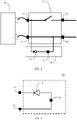
- FIG. 4 shows a possible application scenario according to an embodiment of this application.
- a power supply and distribution system includes a power supply 10, a circuit breaker 20, and a reverse power connection preventing circuit 30.
- the circuit breaker 20 is configured to conduct, carry, or cut off a current between a power supply network and electric equipment. When a circuit between the power supply network or the power supply and the electric equipment needs to be connected, the circuit breaker 20 may be switched to a closed state.
- the circuit breaker 20 When the circuit between the power supply network and the electric equipment needs to be disconnected, the circuit breaker 20 may be switched to an open state.
- the power supply 10 provides a safe, stable, and reliable power guarantee for a communications device when alternating current power supply is interrupted or fails for short time, thereby ensuring normal operation of the communications device.
- the power supply 10 may be a storage battery, an electric generator, or the like. Because the power supply 10 is usually manually connected to the circuit breaker 20, an operational error that cables of the power supply 10 are reversely connected is unavoidable. If the reverse power connection preventing circuit 30 in this application is not disposed, the reverse connection of the power supply 10 may cause device damage and a safety accident.
- the reverse power connection preventing circuit 30 can determine, when the power supply 10 is connected to the circuit breaker 20 and before the circuit breaker 20 is closed, whether the power supply is reversely connected, and perform an early warning or prevent closing of the circuit breaker, to avoid a short-circuit current generated by the reverse connection.
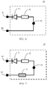
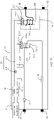
- FIG. 5 is a schematic diagram of a structure of the reverse power connection preventing circuit according to an embodiment of this application.
- the reverse power connection preventing circuit 30 provided in this embodiment of this application includes a diode 31 and an actuation unit 33 that are connected in series.
- the diode 31 and the actuation unit 33 that are connected in series are configured to connect a positive input terminal A1 and a negative input terminal A2 of the circuit breaker.
- a positive electrode of the diode 31 points to the negative wiring terminal A2 of the circuit breaker, and a negative electrode of the diode 31 points to the positive input terminal A1 of the circuit breaker.
- the diode 31 When the power supply is forward connected to the circuit breaker, the diode 31 is cut off, there is no current on the actuation unit 33, and the reverse power connection preventing circuit 30 is in a power-off state.
- the diode 31 When the power supply is reversely connected to the circuit breaker, the diode 31 is conducted, and the actuation unit 33 is configured to prevent closing of the circuit breaker, or the actuation unit 33 is configured to perform an alarm prompt, to perform an early warning to prompt an operator not to close the circuit breaker.
- the actuation unit 33 may be alternatively configured to: when the diode 31 is conducted, prevent closing of the circuit breaker and also perform an alarm prompt. Therefore, a short-circuit accident caused by the reverse connection of the power supply is completely prevented.
- the reverse power connection preventing circuit also ensures safety of on-site construction, thereby fundamentally avoiding a safety risk caused by the reverse connection.
- the reverse power connection preventing circuit provided in this application is simple in structure, so that a volume and costs can be reduced compared with the conventional technology.
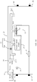
- the reverse power connection preventing circuit 30 provided in this application may further include a current limiting resistor 32.
- the current limiting resistor 32 After being connected in series to the diode 31 and the actuation unit 33, the current limiting resistor 32 is configured to connect the positive input terminal A1 and the negative input terminal A2 of the circuit breaker (not shown in FIG. 6 ).
- the current limiting resistor 32 can limit a current flowing through the diode 31 and the actuation unit 33, thereby reducing power consumption and protecting components.
- the reverse power connection preventing circuit 30 provided in this application may further include a fuse 34.
- the fuse 34 After being connected in series to the current limiting resistor 32, the diode 31, and the actuation unit 33, the fuse 34 is configured to connect the positive input terminal A1 and the negative input terminal A2 of the circuit breaker (not shown in FIG. 7 ). The fuse is blown due to overcurrent during a lightning surge, to prevent a case in which because lightning breaks down the diode, the circuit breaker cannot be normally closed when the power supply is forward connected.
- positions of the diode 31, current limiting resistor 32, actuation unit 33, and fuse 34 are not limited in this application, provided that the four components are connected in series.
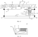
- the circuit breaker 20 may include a housing 21 and a switch on mechanism 22 disposed on the housing 21. Switching of the circuit breaker 20 between the closed state and the open state may be implemented by controlling the switch on mechanism 22.
- the circuit breaker 20 further includes input terminals and output terminals that are disposed in the housing 21. The input terminals are configured to be connected to a power supply line, and the output terminals are configured to be connected to a power receiving line. There are two input terminals: a positive input terminal A1 and a negative input terminal A2.
- the positive input terminal A1 is configured to be connected to a positive electrode of the power supply line
- the negative input terminal A2 is configured to be connected to a negative electrode of the power supply line.
- the positive output terminal B1 is configured to be connected to a positive electrode of the power receiving line
- the negative output terminal B2 is configured to be connected to a negative electrode of the power receiving line.
- the positive input terminal A1 may be electrically connected to the positive output terminal B1
- the negative input terminal A2 may be electrically connected to the negative output terminal B2.
- an on/off control system 23 is usually disposed in the circuit breaker 20.
- a power supply on/off status of the electric equipment can be controlled by controlling either of a connection between the positive input terminal A1 and the positive output terminal B1 and a connection between the negative input terminal A2 and the negative output terminal B2.
- a process of controlling the on/off status between the input terminal and the output terminal in this embodiment of this application is described by using an example in which the on/off control system 23 is disposed between the positive input terminal A1 and the positive output terminal B1.
- a connection manner may be but is not limited to a direct electrical connection performed by using a conducting wire.
- the circuit breaker 20 further includes a slide buckle 24 and a switch off structure 25.
- the switch off structure 25 is configured to: when being driven, control the circuit breaker 20 to be in the open state.
- the switch off structure 25 may include a connecting rod mechanism 251 and a rotating shaft 252.
- the positive input terminal A1 is connected to a first contact Q1 of the on/off control system 23, and the positive output terminal B1 is connected to a second contact Q2 of the on/off control system 23.
- the switch on mechanism 22 When the switch on mechanism 22 is pushed in a direction close to the slide buckle 24, the switch on mechanism 22 pushes the connecting rod mechanism 251 to rotate around the rotating shaft 252, so that a first connecting rod 2511 of the connecting rod mechanism 251 pushes the first contact Q1 of the on/off control system 23 to rotate towards the second contact Q2, until the first contact Q1 is in contact with the second contact Q2. In this way, the positive input terminal A1 and the positive output terminal B1 are in a circuit-conducted state, so that the circuit breaker 20 is closed.
- the connecting rod mechanism 251 rotates around the rotating shaft 252 in a reverse direction, so that the first contact Q1 of the on/off control system 23 rotates in a direction away from the second contact Q2. In this way, the positive input terminal A1 and the positive output terminal B1 are in a circuit-broken state, so that the circuit breaker 20 is open.
- an electromagnetic tripper may be further disposed in the circuit breaker.
- a second electromagnetic tripper 26 in FIG. 8 is used as an example. When the short-circuit failure exists in the power receiving line, the second electromagnetic tripper 26 drives the switch off mechanism 25, so that the switch off structure 25 controls the circuit breaker 20 to be in the open state, thereby implementing short-circuit protection.
- the second electromagnetic tripper 26 mainly includes an electromagnet.
- the second electromagnetic tripper 26 may include a second coil 261, a second iron core 262, and a second armature 263.
- the second coil 261 is sleeved onto the second iron core 262.
- One end of the second coil 261 may be electrically connected to the second contact Q2 by using a conductor (for example, a metal wire or a metal sheet), and the other end may be electrically connected to the positive output terminal B1.
- a current of the positive input terminal A1 flows to the positive output terminal B1 after passing through the conductor and the second coil 261.
- a current flowing through the second coil 261 is excessively large.
- the second coil 261 When the current exceeds a preset current threshold of the circuit breaker 20, the second coil 261 generates a relatively large magnetic field, so that the second iron core 262 generates an electromagnetic force for moving the second armature 263.
- a second connecting rod 2512 of the connecting rod mechanism 251 When the second iron core 262 acts on the second armature 263, a second connecting rod 2512 of the connecting rod mechanism 251 is pushed.
- the second connecting rod 2512 causes the connecting rod mechanism 251 to rotate around the rotating shaft 252, so that the first contact Q1 moves in the direction away from the second contact Q2, until the first contact Q1 is separated from the second contact Q2. Therefore, a current path between the positive input terminal A1 and the positive output terminal B1 is cut off, thereby implementing short-circuit protection.
- an overload failure may alternatively occur in the power receiving line. If the power supply line still supplies electric energy to the power receiving line after the failure occurs, a severer accident may be caused. Therefore, there is a relatively severe safety risk.
- a thermal tripper may be further disposed in the circuit breaker.
- a second thermal tripper 27 in FIG. 8 is used as an example. When the overload failure exists in the power receiving line, the second thermal tripper 27 drives the switch off mechanism 25, so that the switch off structure 25 controls the circuit breaker 20 to be in the open state, thereby implementing overload protection.
- the second thermal tripper 27 may include a first thermal deformation metal.
- One end of the first thermal deformation metal may be electrically connected to the second contact Q2, and the other end may be electrically connected to the positive output terminal B1.
- the overload failure exists in the power receiving line, a large amount of heat is generated in the power receiving line.
- the first thermal deformation metal is deformed, and a third connecting rod 2513 causes the connecting rod mechanism 251 to rotate around the rotating shaft 252, so that the first contact Q1 moves in the direction away from the second contact Q2, until the first contact Q1 is separated from the second contact Q2. Therefore, a current path between the positive input terminal A1 and the positive output terminal B1 is cut off, thereby implementing overload protection.
- the actuation unit may be specifically configured to lock the switch on mechanism when the diode is conducted. That is, when the power supply is reversely connected, the diode in the reverse power connection preventing circuit is conducted. However, because the actuation unit can lock the switch on mechanism, the switch on mechanism can be prevented from being manipulated, thereby preventing closing of the circuit breaker.
- the actuation unit may include a first electromagnet 331, and a clamping slot 332 is disposed on the switch on mechanism 22 of the circuit breaker 20.
- the first electromagnet 331 is connected in series to the diode 31 and the current limiting resistor 32.
- the first electromagnet 331 is configured to: when the diode 31 is conducted, drive an armature of the first electromagnet 331 to be inserted into the clamping slot 332, to lock the switch on mechanism 22 of the circuit breaker 20, thereby preventing closing of the circuit breaker 20.
- the first electromagnet 331 includes a first coil 3311, a first iron core 3312, and a first armature 3313.
- the first coil 3311 is connected in series to the diode 31 and the current limiting resistor 32.
- the diode 31 is conducted, and the first coil 3311 is powered on and drives the first armature 3313 to be inserted into the clamping slot 332, to lock the switch on mechanism 22 of the circuit breaker 20, thereby preventing closing of the circuit breaker 20.
- the power supply is forward connected, referring to FIG. 10b , the diode 31 is cut off, the first armature 3313 is away from the clamping slot 332, and the reverse power connection preventing circuit 30 is in a power-off state and does not act on the circuit breaker 20.
- clamping slot 332 may be disposed at any position that can lock the switch on mechanism 22. This is not limited herein.
- the fuse when a fuse is disposed in the reverse power connection preventing circuit 30, the fuse may be reused as at least a part of the first coil 3311. Specifically, this may be implemented by adjusting a structure and a material of a part of the first coil 3311. This is not limited herein.
- the actuation unit in this application may be specifically configured to drive the switch off mechanism when the diode is conducted. That is, when the power supply is reversely connected, the diode in the reverse power connection preventing circuit is conducted. However, because the actuation unit can drive the switch off mechanism, the switch off mechanism controls the circuit breaker to be in the open state.
- the actuation unit may include a first electromagnetic tripper 334.
- the first electromagnetic tripper 334 is connected in series to the diode 31 and the current limiting resistor 32.
- the first electromagnetic tripper 334 is configured to drive the switch off mechanism 25 of the circuit breaker 20 when the diode 31 is conducted, to control the circuit breaker 20 to be in the open state.
- the first electromagnetic tripper 334 mainly includes an electromagnet.
- the first electromagnetic tripper 334 may include a third coil 3341, a third iron core 3342, and a third armature 3343.
- the third coil 3341 is connected in series to the diode 31 and the current limiting resistor 32.
- the diode 31 is conducted, and a current of the negative input terminal A2 flows to the positive input terminal A1 after passing through the third coil 3341.
- the current flowing through the third coil 3341 generates a relatively large magnetic field, so that the third iron core 3342 generates an electromagnetic force for moving the third armature 3343.
- the third armature 3343 pushes a fourth connecting rod 2514 of the connecting rod mechanism 251.
- the fourth connecting rod 2514 causes the connecting rod mechanism 251 to rotate around the rotating shaft 252, so that the first contact moves in the direction away from the second contact, until the first contact is separated from the second contact. Therefore, a current path between the positive input terminal A1 and the positive output terminal B1 is cut off, so that the circuit breaker 20 is in the open state.
- the second iron core 262 of the second electromagnetic tripper 26 is reused as a third iron core of the first electromagnetic tripper, and the second armature 263 of the second electromagnetic tripper 26 is reused as an armature of the first electromagnetic tripper. That is, the third coil 3341 is sleeved onto the second iron core 262 of the second electromagnetic tripper 26.
- the diode 31 is conducted, and a current of the negative input terminal A2 flows to the positive input terminal A1 after passing through the third coil 3341.
- the current flowing through the third coil 3341 generates a relatively large magnetic field, so that the second iron core 262 generates an electromagnetic force for moving the second armature 263.
- the second connecting rod 2512 of the connecting rod mechanism 251 is pushed.
- the second connecting rod 2512 causes the connecting rod mechanism 251 to rotate around the rotating shaft 252, so that the first contact moves in the direction away from the second contact, until the first contact is separated from the second contact. Therefore, a current path between the positive input terminal A1 and the positive output terminal B1 is cut off, so that the circuit breaker 20 is in the open state.
- the original components of the second electromagnetic tripper 26 are reused.
- the actuation unit 33 includes only the third coil 3341 sleeved onto the second iron core 262 of the second electromagnetic tripper 26. Therefore, a structure of the reverse power connection preventing circuit is simplified, so that both a volume of the reverse power connection preventing circuit and costs can be reduced.
- the fuse when a fuse is disposed in the reverse power connection preventing circuit 30, the fuse may be reused as at least a part of the third coil 3341. Specifically, this may be implemented by adjusting a structure and a material of a part of the third coil 3341. This is not limited herein.
- the electromagnet has a plurality of structural forms. Based on a magnetic path system form, the plurality of structural forms may be classified into a snap-fit type, a disk type, an E-shaped type, a solenoid type, and the like. Based on an armature movement manner, the plurality of structural forms may be classified into a rotating type and a direct-acting type. This is not limited herein.
- an electromagnet 40 mainly includes three parts: a coil 41, an iron core 42, and an armature 43.
- the iron core 42 and the armature 43 are usually made of a soft magnetic material, the iron core 42 is usually stationary, and the coil 41 is sleeved onto the iron core.
- the electromagnet 40 further includes a spring.
- the coil 41 When the coil 41 is powered on, the iron core and the armature are magnetized to become two magnets with opposite polarity or same polarity.
- An electromagnetic attraction force or repulsion force is generated between the two magnets.
- the attraction force or repulsion force is greater than a reaction force of the spring, the armature starts to move towards the iron core 42 or against the iron core 42.
- a current in the coil 41 is less than a preset value, or power supply is interrupted, an electromagnetic force is less than a reaction force of the spring, and the armature 43 returns to an original release position under the action of the reaction force.
- the actuation unit 33 includes a first thermal tripper 335.
- the first thermal tripper 335 is connected in series to the diode 31 and the current limiting resistor 32.
- the first thermal tripper 335 is configured to drive the switch off mechanism 25 of the circuit breaker 20 when the diode 31 is conducted, to control the circuit breaker 20 to be in the open state.
- the first thermal tripper 335 includes a second thermal deformation metal, and the second thermal deformation metal is connected in series to the diode 31 and the current limiting resistor 32.
- the original second thermal tripper 27 in the circuit breaker 20 is reused as the first thermal tripper 335, and the second thermal tripper 27 needs to be connected in series to the diode 31 and the current limiting resistor 32.
- the diode 31 is conducted, the first thermal deformation metal in the second thermal tripper 27 is deformed, and the third connecting rod 2513 causes the connecting rod mechanism 251 to rotate around the rotating shaft 252, so that the first contact moves in the direction away from the second contact, until the first contact is separated from the second contact. Therefore, a current path between the positive input terminal A1 and the positive output terminal B1 is cut off, so that the circuit breaker 20 is in the open state.
- the second thermal tripper 27 is reused as the first thermal tripper 335, to avoid adding an additional thermal tripper. Therefore, a structure of the reverse power connection preventing circuit is simplified, so that both a volume of the reverse power connection preventing circuit and costs can be reduced.
- the actuation unit 33 includes a heat emitting element.
- the heat emitting element is connected in series to the diode 31 and the current limiting resistor 32.
- the heat emitting element is configured to deform the first thermal deformation metal of the second thermal tripper 27 in the circuit breaker 20 when the diode is conducted, to drive the switch off mechanism 25 of the circuit breaker 20 to control the circuit breaker 20 to be in the open state.
- the heat emitting element deforms the first thermal deformation metal of the second thermal tripper 27 in the circuit breaker 20, and the third connecting rod 2513 causes the connecting rod mechanism 251 to rotate around the rotating shaft 252, so that the first contact moves in the direction away from the second contact, until the first contact is separated from the second contact. Therefore, a current path between the positive input terminal A1 and the positive output terminal B1 is cut off, so that the circuit breaker 20 is in the open state.
- the thermal deformation metal may be made of a shape memory alloy.
- the shape memory alloy is a material that has a shape memory effect through thermoelasticity, Martensite phase transformation, and inverse Martensite phase transformation and that is made of more than two metal elements.
- the thermal deformation metal made of the shape memory alloy may be embodied as follows: After being plastically deformed in a specific temperature range, the thermal deformation metal can recover to an original shape in another temperature range. For example, at a normal temperature or a relatively low temperature, the thermal deformation metal made of the shape memory alloy keeps or approximately keeps in a straight line shape after being straightened. After the thermal deformation metal is heated to a specific temperature, the thermal deformation metal may automatically recover to an original curve shape.
- the thermal deformation metal may be alternatively made of a bimetallic finger.
- the bimetallic finger is a composite material made of two or more metals or other materials with proper properties.
- the bimetallic finger is also referred to as a thermal bimetallic finger. Due to different coefficients of thermal expansion of component layers, when a temperature changes, deformation of an active layer is greater than deformation of a passive layer, so that the entire bimetallic finger bends toward a passive layer side.
- the actuation unit in this application may include a buzzer and/or a prompt light.
- the diode When the power supply is reversely connected, the diode is conducted, and the buzzer sends a sound alarm, the prompt light sends a light alarm, or the buzzer sends a sound alarm and simultaneously the prompt light sends a light alarm, to perform an early warning to prompt an operator not to close the circuit breaker.
- the power supply When the power supply is forward connected, the diode is cut off, and the actuation unit is not powered on.
- the third case is combined with the first case or the second case. That is, in this application, when an implementation of the actuation unit is the first case or the second case, the actuation unit may further include a buzzer and/or a prompt light. In this way, when the power supply is reversely connected, the reverse power connection preventing circuit can prevent closing of the circuit breaker, and also perform an alarm prompt.
- this application further provides a power distribution apparatus 100, including a circuit breaker 20 and a reverse power connection preventing circuit 30.
- the reverse power connection preventing circuit 30 is connected to a positive input terminal A1 and a negative input terminal A2 of the circuit breaker 20.
- a problem resolving principle of the power distribution apparatus 100 is similar to that of the foregoing reverse power connection preventing circuit 30. Therefore, for an implementation of the power distribution apparatus 100, refer to the foregoing implementation of the reverse power connection preventing circuit 30. Repeated parts are not described again.
- this application further provides a power supply and distribution system 1000, including a power supply 10 and a power distribution apparatus 100.
- a positive electrode of the power supply 10 is connected to a positive input terminal A1 of a circuit breaker 20 in the power distribution apparatus 100, and a negative electrode of the power supply 10 is connected to a negative input terminal A2 of the circuit breaker 20 in the power distribution apparatus 100.
- the power supply and distribution system 1000 may be a power supply and distribution system of a 5G (5th generation, 5G for short) high-power radio base station, or may be a power supply and distribution system of a home circuit.
- An application field of the power supply and distribution system 1000 is not limited in this embodiment, and the power supply and distribution system 1000 may be applied to a line connection in any field.
Landscapes
- Emergency Protection Circuit Devices (AREA)
Applications Claiming Priority (2)
| Application Number | Priority Date | Filing Date | Title |
|---|---|---|---|
| CN202011269747.9A CN112510670B (zh) | 2020-11-13 | 2020-11-13 | 防电源反接电路、配电装置及供配电系统 |
| PCT/CN2021/097935 WO2022100074A1 (zh) | 2020-11-13 | 2021-06-02 | 防电源反接电路、配电装置及供配电系统 |
Publications (3)
| Publication Number | Publication Date |
|---|---|
| EP4084251A1 true EP4084251A1 (de) | 2022-11-02 |
| EP4084251A4 EP4084251A4 (de) | 2023-08-30 |
| EP4084251B1 EP4084251B1 (de) | 2025-03-26 |
Family
ID=74957530
Family Applications (1)
| Application Number | Title | Priority Date | Filing Date |
|---|---|---|---|
| EP21890605.5A Active EP4084251B1 (de) | 2020-11-13 | 2021-06-02 | Schaltung zur verhinderung des umgekehrten anschlusses einer stromquelle, stromverteilungsvorrichtung und stromversorgungs- und verteilungssystem |
Country Status (4)
| Country | Link |
|---|---|
| US (1) | US11936175B2 (de) |
| EP (1) | EP4084251B1 (de) |
| CN (1) | CN112510670B (de) |
| WO (1) | WO2022100074A1 (de) |
Families Citing this family (4)
| Publication number | Priority date | Publication date | Assignee | Title |
|---|---|---|---|---|
| CN112510670B (zh) | 2020-11-13 | 2022-08-09 | 华为数字能源技术有限公司 | 防电源反接电路、配电装置及供配电系统 |
| CN115932655A (zh) * | 2023-01-05 | 2023-04-07 | 桂林电子科技大学 | 一种火线和零线自矫正装置 |
| CN116436146B (zh) * | 2023-06-13 | 2023-09-12 | 苏州浪潮智能科技有限公司 | 掉电保持电路、供电保护方法、供电控制电路及装置 |
| CN118920639B (zh) * | 2024-07-22 | 2025-04-01 | 江西米聚科技有限公司 | 一种防反接的锂电池充电器及应用方法 |
Family Cites Families (27)
| Publication number | Priority date | Publication date | Assignee | Title |
|---|---|---|---|---|
| JP2992449B2 (ja) * | 1994-11-15 | 1999-12-20 | 松下電工株式会社 | 回路遮断器 |
| JPH08315666A (ja) * | 1995-05-12 | 1996-11-29 | Mitsubishi Electric Corp | 遮断器および遮断装置 |
| US6078160A (en) * | 1997-10-31 | 2000-06-20 | Cilluffo; Anthony | Bidirectional DC motor control circuit including overcurrent protection PTC device and relay |
| US6657839B2 (en) * | 2000-08-25 | 2003-12-02 | Tyco Electronics Corporation | Protective relay |
| JP2002157946A (ja) * | 2000-11-20 | 2002-05-31 | Mitsubishi Electric Corp | 開閉器の操作装置 |
| US6680548B2 (en) * | 2001-11-20 | 2004-01-20 | Luxon Energy Devices Corporation | Electronic timers using supercapacitors |
| US8203810B2 (en) * | 2006-04-04 | 2012-06-19 | Tyco Electronics Corporation | Solid state pre-charge module |
| CN2911950Y (zh) * | 2006-04-22 | 2007-06-13 | 陈贵 | 具有故障指示及强制脱扣功能的gfci |
| US7616421B2 (en) * | 2006-12-18 | 2009-11-10 | Caterpillar Inc. | Electrical interface system |
| CN101630611B (zh) * | 2008-07-15 | 2012-04-18 | 浙江正泰电器股份有限公司 | 选择性保护断路器 |
| US9142951B2 (en) * | 2009-07-28 | 2015-09-22 | Stmicroelectronics (Rousset) Sas | Electronic device for protecting against a polarity reversal of a DC power supply voltage, and its application to motor vehicles |
| CN102339696B (zh) * | 2010-07-15 | 2014-09-24 | 北京翠祥电器元件有限公司 | 具有选择性保护的断路器 |
| EP2498369B1 (de) * | 2011-06-08 | 2015-03-25 | Huawei Technologies Co., Ltd. | Steuerschaltung zur verhinderung des umgekehrten anschlusses einer batteriegruppe und stromversorgungssystem für eine basisstation |
| CN102496923B (zh) * | 2011-11-14 | 2016-10-19 | 株洲南车时代电气股份有限公司 | 一种防反接保护的输入电路 |
| CN103545804B (zh) * | 2013-07-23 | 2017-02-08 | 特变电工新疆新能源股份有限公司 | 一种直流输入端防反接保护电路和方法、直流输入设备 |
| CN103489723A (zh) | 2013-08-29 | 2014-01-01 | 董刚 | 可以连接传感器的空气开关 |
| CN204480986U (zh) | 2015-03-31 | 2015-07-15 | 江苏华唐电器有限公司 | 断路器合闸闭锁机构 |
| DE102015214966A1 (de) * | 2015-08-05 | 2017-02-09 | Ellenberger & Poensgen Gmbh | Schutzschalter |
| US10326267B2 (en) * | 2016-03-15 | 2019-06-18 | Littelfuse, Inc. | Method and apparatus for protecting a polarity sensitive load |
| CN107578936A (zh) | 2017-10-11 | 2018-01-12 | 孝感汉光森源电气有限责任公司 | 一种断路器用合闸闭锁装置 |
| CN108305820B (zh) | 2018-02-23 | 2019-10-25 | 南京飞腾电子科技有限公司 | 一种断路器 |
| CN208608710U (zh) | 2018-08-29 | 2019-03-15 | 北京新能源汽车股份有限公司 | 一种过载保护装置和汽车 |
| CN209448232U (zh) * | 2018-12-21 | 2019-09-27 | 华为数字技术(苏州)有限公司 | 一种配电设备及配电系统 |
| CN109546642B (zh) * | 2019-01-02 | 2021-04-13 | 阳光电源股份有限公司 | 一种逆变器直流输入反接保护模块和装置 |
| US11551899B2 (en) * | 2019-05-18 | 2023-01-10 | Amber Semiconductor, Inc. | Intelligent circuit breakers with solid-state bidirectional switches |
| EP4148931B1 (de) * | 2020-06-15 | 2025-11-26 | Huawei Digital Power Technologies Co., Ltd. | Schutzschaltung zur verhinderung der fehlverbindung von eingangsenden und fotovoltaisches stromerzeugungssystem |
| CN112510670B (zh) * | 2020-11-13 | 2022-08-09 | 华为数字能源技术有限公司 | 防电源反接电路、配电装置及供配电系统 |
-
2020
- 2020-11-13 CN CN202011269747.9A patent/CN112510670B/zh active Active
-
2021
- 2021-06-02 EP EP21890605.5A patent/EP4084251B1/de active Active
- 2021-06-02 WO PCT/CN2021/097935 patent/WO2022100074A1/zh not_active Ceased
-
2022
- 2022-07-15 US US17/865,656 patent/US11936175B2/en active Active
Also Published As
| Publication number | Publication date |
|---|---|
| US11936175B2 (en) | 2024-03-19 |
| CN112510670B (zh) | 2022-08-09 |
| WO2022100074A1 (zh) | 2022-05-19 |
| US20220352713A1 (en) | 2022-11-03 |
| CN112510670A (zh) | 2021-03-16 |
| EP4084251B1 (de) | 2025-03-26 |
| EP4084251A4 (de) | 2023-08-30 |
Similar Documents
| Publication | Publication Date | Title |
|---|---|---|
| US11936175B2 (en) | Reverse power connection preventing circuit, power distribution apparatus, and power supply and distribution system | |
| US6570269B2 (en) | Method and apparatus for supplying power to a load circuit from alternate electric power sources | |
| CN114430877B (zh) | 电流断路装置以及电流断路方法 | |
| US12308191B2 (en) | Circuit breaker and power distribution box | |
| JP2007157700A (ja) | 超電導体を利用する電力回路保護装置 | |
| US9312084B2 (en) | Contact slider unit for a switching unit, in particular for a circuit breaker | |
| RU2658349C2 (ru) | Гибридное устройство отключения для электрической цепи | |
| CN107864683B (zh) | 电流断续器 | |
| CN220367830U (zh) | 断路器 | |
| EP2731122B1 (de) | Magnetischer wärmeschutzschalter und energieverteilungsvorrichtung | |
| CN202231403U (zh) | 一种永磁操动机构的合闸保护装置 | |
| CN114450865A (zh) | 防电源反接电路、配电装置及供配电系统 | |
| US9362067B2 (en) | Contact slider unit for a switching unit, in particular for a circuit breaker | |
| CN113257639B (zh) | 一种断路器和配电盒 | |
| EP1218899B1 (de) | Elektrischer pol für einen niederspannungsschutzschalter | |
| JP2013535072A (ja) | 短絡故障状態の早期検出のための自動的かつ自律的な電子システム | |
| CN222762902U (zh) | 一种断路器及配电设备 | |
| CN104992887A (zh) | 一种永磁机构断路器的欠压脱扣装置 | |
| CN224037071U (zh) | 电流保护装置及供电系统 | |
| CN221708643U (zh) | 后备保护分断器及浪涌保护器 | |
| US11509159B2 (en) | System and method for thermal cutoff protection device control from an external component | |
| CN121813270A (zh) | 直流断路器及其控制方法 | |
| CN121356323A (zh) | 一种换流阀功率模块的旁路装置及其控制方法 | |
| KR20040003596A (ko) | 배선용 차단기의 트립부 구조 | |
| CN121395670A (zh) | 一种双电源自动转换装置 |
Legal Events
| Date | Code | Title | Description |
|---|---|---|---|
| STAA | Information on the status of an ep patent application or granted ep patent |
Free format text: STATUS: THE INTERNATIONAL PUBLICATION HAS BEEN MADE |
|
| PUAI | Public reference made under article 153(3) epc to a published international application that has entered the european phase |
Free format text: ORIGINAL CODE: 0009012 |
|
| STAA | Information on the status of an ep patent application or granted ep patent |
Free format text: STATUS: REQUEST FOR EXAMINATION WAS MADE |
|
| 17P | Request for examination filed |
Effective date: 20220725 |
|
| AK | Designated contracting states |
Kind code of ref document: A1 Designated state(s): AL AT BE BG CH CY CZ DE DK EE ES FI FR GB GR HR HU IE IS IT LI LT LU LV MC MK MT NL NO PL PT RO RS SE SI SK SM TR |
|
| A4 | Supplementary search report drawn up and despatched |
Effective date: 20230731 |
|
| RIC1 | Information provided on ipc code assigned before grant |
Ipc: H02H 11/00 20060101AFI20230725BHEP |
|
| DAV | Request for validation of the european patent (deleted) | ||
| DAX | Request for extension of the european patent (deleted) | ||
| STAA | Information on the status of an ep patent application or granted ep patent |
Free format text: STATUS: EXAMINATION IS IN PROGRESS |
|
| 17Q | First examination report despatched |
Effective date: 20240319 |
|
| GRAP | Despatch of communication of intention to grant a patent |
Free format text: ORIGINAL CODE: EPIDOSNIGR1 |
|
| STAA | Information on the status of an ep patent application or granted ep patent |
Free format text: STATUS: GRANT OF PATENT IS INTENDED |
|
| INTG | Intention to grant announced |
Effective date: 20241126 |
|
| GRAS | Grant fee paid |
Free format text: ORIGINAL CODE: EPIDOSNIGR3 |
|
| GRAA | (expected) grant |
Free format text: ORIGINAL CODE: 0009210 |
|
| STAA | Information on the status of an ep patent application or granted ep patent |
Free format text: STATUS: THE PATENT HAS BEEN GRANTED |
|
| P01 | Opt-out of the competence of the unified patent court (upc) registered |
Free format text: CASE NUMBER: APP_4468/2025 Effective date: 20250127 |
|
| AK | Designated contracting states |
Kind code of ref document: B1 Designated state(s): AL AT BE BG CH CY CZ DE DK EE ES FI FR GB GR HR HU IE IS IT LI LT LU LV MC MK MT NL NO PL PT RO RS SE SI SK SM TR |
|
| REG | Reference to a national code |
Ref country code: GB Ref legal event code: FG4D |
|
| REG | Reference to a national code |
Ref country code: CH Ref legal event code: EP |
|
| REG | Reference to a national code |
Ref country code: DE Ref legal event code: R096 Ref document number: 602021028307 Country of ref document: DE |
|
| REG | Reference to a national code |
Ref country code: IE Ref legal event code: FG4D |
|
| PG25 | Lapsed in a contracting state [announced via postgrant information from national office to epo] |
Ref country code: RS Free format text: LAPSE BECAUSE OF FAILURE TO SUBMIT A TRANSLATION OF THE DESCRIPTION OR TO PAY THE FEE WITHIN THE PRESCRIBED TIME-LIMIT Effective date: 20250626 |
|
| PG25 | Lapsed in a contracting state [announced via postgrant information from national office to epo] |
Ref country code: FI Free format text: LAPSE BECAUSE OF FAILURE TO SUBMIT A TRANSLATION OF THE DESCRIPTION OR TO PAY THE FEE WITHIN THE PRESCRIBED TIME-LIMIT Effective date: 20250326 |
|
| REG | Reference to a national code |
Ref country code: LT Ref legal event code: MG9D |
|
| PG25 | Lapsed in a contracting state [announced via postgrant information from national office to epo] |
Ref country code: NO Free format text: LAPSE BECAUSE OF FAILURE TO SUBMIT A TRANSLATION OF THE DESCRIPTION OR TO PAY THE FEE WITHIN THE PRESCRIBED TIME-LIMIT Effective date: 20250626 |
|
| PG25 | Lapsed in a contracting state [announced via postgrant information from national office to epo] |
Ref country code: HR Free format text: LAPSE BECAUSE OF FAILURE TO SUBMIT A TRANSLATION OF THE DESCRIPTION OR TO PAY THE FEE WITHIN THE PRESCRIBED TIME-LIMIT Effective date: 20250326 |
|
| PG25 | Lapsed in a contracting state [announced via postgrant information from national office to epo] |
Ref country code: LV Free format text: LAPSE BECAUSE OF FAILURE TO SUBMIT A TRANSLATION OF THE DESCRIPTION OR TO PAY THE FEE WITHIN THE PRESCRIBED TIME-LIMIT Effective date: 20250326 |
|
| PG25 | Lapsed in a contracting state [announced via postgrant information from national office to epo] |
Ref country code: GR Free format text: LAPSE BECAUSE OF FAILURE TO SUBMIT A TRANSLATION OF THE DESCRIPTION OR TO PAY THE FEE WITHIN THE PRESCRIBED TIME-LIMIT Effective date: 20250627 Ref country code: BG Free format text: LAPSE BECAUSE OF FAILURE TO SUBMIT A TRANSLATION OF THE DESCRIPTION OR TO PAY THE FEE WITHIN THE PRESCRIBED TIME-LIMIT Effective date: 20250326 |
|
| PGFP | Annual fee paid to national office [announced via postgrant information from national office to epo] |
Ref country code: AT Payment date: 20250721 Year of fee payment: 5 |
|
| REG | Reference to a national code |
Ref country code: NL Ref legal event code: MP Effective date: 20250326 |
|
| PG25 | Lapsed in a contracting state [announced via postgrant information from national office to epo] |
Ref country code: NL Free format text: LAPSE BECAUSE OF FAILURE TO SUBMIT A TRANSLATION OF THE DESCRIPTION OR TO PAY THE FEE WITHIN THE PRESCRIBED TIME-LIMIT Effective date: 20250326 |
|
| PG25 | Lapsed in a contracting state [announced via postgrant information from national office to epo] |
Ref country code: SE Free format text: LAPSE BECAUSE OF FAILURE TO SUBMIT A TRANSLATION OF THE DESCRIPTION OR TO PAY THE FEE WITHIN THE PRESCRIBED TIME-LIMIT Effective date: 20250326 |
|
| REG | Reference to a national code |
Ref country code: AT Ref legal event code: MK05 Ref document number: 1779935 Country of ref document: AT Kind code of ref document: T Effective date: 20250326 |
|
| PG25 | Lapsed in a contracting state [announced via postgrant information from national office to epo] |
Ref country code: SM Free format text: LAPSE BECAUSE OF FAILURE TO SUBMIT A TRANSLATION OF THE DESCRIPTION OR TO PAY THE FEE WITHIN THE PRESCRIBED TIME-LIMIT Effective date: 20250326 |
|
| PG25 | Lapsed in a contracting state [announced via postgrant information from national office to epo] |
Ref country code: ES Free format text: LAPSE BECAUSE OF FAILURE TO SUBMIT A TRANSLATION OF THE DESCRIPTION OR TO PAY THE FEE WITHIN THE PRESCRIBED TIME-LIMIT Effective date: 20250326 Ref country code: PT Free format text: LAPSE BECAUSE OF FAILURE TO SUBMIT A TRANSLATION OF THE DESCRIPTION OR TO PAY THE FEE WITHIN THE PRESCRIBED TIME-LIMIT Effective date: 20250728 |
|
| PG25 | Lapsed in a contracting state [announced via postgrant information from national office to epo] |
Ref country code: IT Free format text: LAPSE BECAUSE OF FAILURE TO SUBMIT A TRANSLATION OF THE DESCRIPTION OR TO PAY THE FEE WITHIN THE PRESCRIBED TIME-LIMIT Effective date: 20250326 Ref country code: PL Free format text: LAPSE BECAUSE OF FAILURE TO SUBMIT A TRANSLATION OF THE DESCRIPTION OR TO PAY THE FEE WITHIN THE PRESCRIBED TIME-LIMIT Effective date: 20250326 |
|
| PG25 | Lapsed in a contracting state [announced via postgrant information from national office to epo] |
Ref country code: AT Free format text: LAPSE BECAUSE OF FAILURE TO SUBMIT A TRANSLATION OF THE DESCRIPTION OR TO PAY THE FEE WITHIN THE PRESCRIBED TIME-LIMIT Effective date: 20250326 |
|
| PG25 | Lapsed in a contracting state [announced via postgrant information from national office to epo] |
Ref country code: EE Free format text: LAPSE BECAUSE OF FAILURE TO SUBMIT A TRANSLATION OF THE DESCRIPTION OR TO PAY THE FEE WITHIN THE PRESCRIBED TIME-LIMIT Effective date: 20250326 |
|
| PG25 | Lapsed in a contracting state [announced via postgrant information from national office to epo] |
Ref country code: RO Free format text: LAPSE BECAUSE OF FAILURE TO SUBMIT A TRANSLATION OF THE DESCRIPTION OR TO PAY THE FEE WITHIN THE PRESCRIBED TIME-LIMIT Effective date: 20250326 |
|
| PG25 | Lapsed in a contracting state [announced via postgrant information from national office to epo] |
Ref country code: SK Free format text: LAPSE BECAUSE OF FAILURE TO SUBMIT A TRANSLATION OF THE DESCRIPTION OR TO PAY THE FEE WITHIN THE PRESCRIBED TIME-LIMIT Effective date: 20250326 |
|
| PG25 | Lapsed in a contracting state [announced via postgrant information from national office to epo] |
Ref country code: IS Free format text: LAPSE BECAUSE OF FAILURE TO SUBMIT A TRANSLATION OF THE DESCRIPTION OR TO PAY THE FEE WITHIN THE PRESCRIBED TIME-LIMIT Effective date: 20250726 |
|
| REG | Reference to a national code |
Ref country code: DE Ref legal event code: R097 Ref document number: 602021028307 Country of ref document: DE |
|
| PG25 | Lapsed in a contracting state [announced via postgrant information from national office to epo] |
Ref country code: DK Free format text: LAPSE BECAUSE OF FAILURE TO SUBMIT A TRANSLATION OF THE DESCRIPTION OR TO PAY THE FEE WITHIN THE PRESCRIBED TIME-LIMIT Effective date: 20250326 |
|
| PG25 | Lapsed in a contracting state [announced via postgrant information from national office to epo] |
Ref country code: CZ Free format text: LAPSE BECAUSE OF FAILURE TO SUBMIT A TRANSLATION OF THE DESCRIPTION OR TO PAY THE FEE WITHIN THE PRESCRIBED TIME-LIMIT Effective date: 20250326 |
|
| REG | Reference to a national code |
Ref country code: CH Ref legal event code: H13 Free format text: ST27 STATUS EVENT CODE: U-0-0-H10-H13 (AS PROVIDED BY THE NATIONAL OFFICE) Effective date: 20260127 |
|
| PG25 | Lapsed in a contracting state [announced via postgrant information from national office to epo] |
Ref country code: MC Free format text: LAPSE BECAUSE OF FAILURE TO SUBMIT A TRANSLATION OF THE DESCRIPTION OR TO PAY THE FEE WITHIN THE PRESCRIBED TIME-LIMIT Effective date: 20250326 |
|
| PLBE | No opposition filed within time limit |
Free format text: ORIGINAL CODE: 0009261 |
|
| STAA | Information on the status of an ep patent application or granted ep patent |
Free format text: STATUS: NO OPPOSITION FILED WITHIN TIME LIMIT |
|
| REG | Reference to a national code |
Ref country code: CH Ref legal event code: L10 Free format text: ST27 STATUS EVENT CODE: U-0-0-L10-L00 (AS PROVIDED BY THE NATIONAL OFFICE) Effective date: 20260211 |
|
| PG25 | Lapsed in a contracting state [announced via postgrant information from national office to epo] |
Ref country code: LU Free format text: LAPSE BECAUSE OF NON-PAYMENT OF DUE FEES Effective date: 20250602 |
|
| GBPC | Gb: european patent ceased through non-payment of renewal fee |
Effective date: 20250626 |
|
| REG | Reference to a national code |
Ref country code: BE Ref legal event code: MM Effective date: 20250630 |
|
| 26N | No opposition filed |
Effective date: 20260105 |
|
| PG25 | Lapsed in a contracting state [announced via postgrant information from national office to epo] |
Ref country code: GB Free format text: LAPSE BECAUSE OF NON-PAYMENT OF DUE FEES Effective date: 20250626 |
|
| PG25 | Lapsed in a contracting state [announced via postgrant information from national office to epo] |
Ref country code: IE Free format text: LAPSE BECAUSE OF NON-PAYMENT OF DUE FEES Effective date: 20250602 |
|
| PG25 | Lapsed in a contracting state [announced via postgrant information from national office to epo] |
Ref country code: BE Free format text: LAPSE BECAUSE OF NON-PAYMENT OF DUE FEES Effective date: 20250630 |
|
| PG25 | Lapsed in a contracting state [announced via postgrant information from national office to epo] |
Ref country code: FR Free format text: LAPSE BECAUSE OF NON-PAYMENT OF DUE FEES Effective date: 20250630 |
|
| PG25 | Lapsed in a contracting state [announced via postgrant information from national office to epo] |
Ref country code: CH Free format text: LAPSE BECAUSE OF NON-PAYMENT OF DUE FEES Effective date: 20250630 |
|
| PG25 | Lapsed in a contracting state [announced via postgrant information from national office to epo] |
Ref country code: LT Free format text: LAPSE BECAUSE OF FAILURE TO SUBMIT A TRANSLATION OF THE DESCRIPTION OR TO PAY THE FEE WITHIN THE PRESCRIBED TIME-LIMIT Effective date: 20250326 |
|
| PGFP | Annual fee paid to national office [announced via postgrant information from national office to epo] |
Ref country code: DE Payment date: 20260506 Year of fee payment: 6 |
|
| PG25 | Lapsed in a contracting state [announced via postgrant information from national office to epo] |
Ref country code: CY Free format text: LAPSE BECAUSE OF FAILURE TO SUBMIT A TRANSLATION OF THE DESCRIPTION OR TO PAY THE FEE WITHIN THE PRESCRIBED TIME-LIMIT Effective date: 20250326 |