EP4084257A1 - Agencement de commande d'une centrale éolienne - Google Patents
Agencement de commande d'une centrale éolienne Download PDFInfo
- Publication number
- EP4084257A1 EP4084257A1 EP21171198.1A EP21171198A EP4084257A1 EP 4084257 A1 EP4084257 A1 EP 4084257A1 EP 21171198 A EP21171198 A EP 21171198A EP 4084257 A1 EP4084257 A1 EP 4084257A1
- Authority
- EP
- European Patent Office
- Prior art keywords
- power
- wind
- grid
- sub
- control arrangement
- Prior art date
- Legal status (The legal status is an assumption and is not a legal conclusion. Google has not performed a legal analysis and makes no representation as to the accuracy of the status listed.)
- Ceased
Links
Images




Classifications
-
- F—MECHANICAL ENGINEERING; LIGHTING; HEATING; WEAPONS; BLASTING
- F03—MACHINES OR ENGINES FOR LIQUIDS; WIND, SPRING, OR WEIGHT MOTORS; PRODUCING MECHANICAL POWER OR A REACTIVE PROPULSIVE THRUST, NOT OTHERWISE PROVIDED FOR
- F03D—WIND MOTORS
- F03D7/00—Controlling wind motors
- F03D7/02—Controlling wind motors the wind motors having rotation axis substantially parallel to the air flow entering the rotor
- F03D7/028—Controlling wind motors the wind motors having rotation axis substantially parallel to the air flow entering the rotor controlling wind motor output power
- F03D7/0284—Controlling wind motors the wind motors having rotation axis substantially parallel to the air flow entering the rotor controlling wind motor output power in relation to the state of the electric grid
-
- H—ELECTRICITY
- H02—GENERATION; CONVERSION OR DISTRIBUTION OF ELECTRIC POWER
- H02J—ELECTRIC POWER NETWORKS; CIRCUIT ARRANGEMENTS OR SYSTEMS FOR SUPPLYING OR DISTRIBUTING ELECTRIC POWER; SYSTEMS FOR STORING ELECTRIC ENERGY
- H02J3/00—Circuit arrangements for AC mains or AC distribution networks
- H02J3/38—Arrangements for feeding a single network from two or more generators or sources in parallel; Arrangements for feeding already energised networks from additional generators or sources in parallel
- H02J3/381—Dispersed generators
-
- H—ELECTRICITY
- H02—GENERATION; CONVERSION OR DISTRIBUTION OF ELECTRIC POWER
- H02J—ELECTRIC POWER NETWORKS; CIRCUIT ARRANGEMENTS OR SYSTEMS FOR SUPPLYING OR DISTRIBUTING ELECTRIC POWER; SYSTEMS FOR STORING ELECTRIC ENERGY
- H02J13/00—Circuit arrangements for providing remote monitoring or remote control of equipment in a power distribution network
- H02J13/12—Monitoring network conditions, e.g. electrical magnitudes or operational status
-
- H—ELECTRICITY
- H02—GENERATION; CONVERSION OR DISTRIBUTION OF ELECTRIC POWER
- H02J—ELECTRIC POWER NETWORKS; CIRCUIT ARRANGEMENTS OR SYSTEMS FOR SUPPLYING OR DISTRIBUTING ELECTRIC POWER; SYSTEMS FOR STORING ELECTRIC ENERGY
- H02J3/00—Circuit arrangements for AC mains or AC distribution networks
- H02J3/28—Arrangements for balancing of the load in networks by storage of energy
- H02J3/30—Arrangements for balancing of the load in networks by storage of energy using dynamo-electric machines coupled to flywheels
-
- H—ELECTRICITY
- H02—GENERATION; CONVERSION OR DISTRIBUTION OF ELECTRIC POWER
- H02J—ELECTRIC POWER NETWORKS; CIRCUIT ARRANGEMENTS OR SYSTEMS FOR SUPPLYING OR DISTRIBUTING ELECTRIC POWER; SYSTEMS FOR STORING ELECTRIC ENERGY
- H02J3/00—Circuit arrangements for AC mains or AC distribution networks
- H02J3/38—Arrangements for feeding a single network from two or more generators or sources in parallel; Arrangements for feeding already energised networks from additional generators or sources in parallel
- H02J3/46—Controlling the sharing of generated power between the generators, sources or networks
- H02J3/48—Controlling the sharing of active power
-
- F—MECHANICAL ENGINEERING; LIGHTING; HEATING; WEAPONS; BLASTING
- F05—INDEXING SCHEMES RELATING TO ENGINES OR PUMPS IN VARIOUS SUBCLASSES OF CLASSES F01-F04
- F05B—INDEXING SCHEME RELATING TO WIND, SPRING, WEIGHT, INERTIA OR LIKE MOTORS, TO MACHINES OR ENGINES FOR LIQUIDS COVERED BY SUBCLASSES F03B, F03D AND F03G
- F05B2270/00—Control
- F05B2270/10—Purpose of the control system
- F05B2270/103—Purpose of the control system to affect the output of the engine
- F05B2270/1033—Power (if explicitly mentioned)
-
- F—MECHANICAL ENGINEERING; LIGHTING; HEATING; WEAPONS; BLASTING
- F05—INDEXING SCHEMES RELATING TO ENGINES OR PUMPS IN VARIOUS SUBCLASSES OF CLASSES F01-F04
- F05B—INDEXING SCHEME RELATING TO WIND, SPRING, WEIGHT, INERTIA OR LIKE MOTORS, TO MACHINES OR ENGINES FOR LIQUIDS COVERED BY SUBCLASSES F03B, F03D AND F03G
- F05B2270/00—Control
- F05B2270/30—Control parameters, e.g. input parameters
- F05B2270/32—Wind speeds
-
- F—MECHANICAL ENGINEERING; LIGHTING; HEATING; WEAPONS; BLASTING
- F05—INDEXING SCHEMES RELATING TO ENGINES OR PUMPS IN VARIOUS SUBCLASSES OF CLASSES F01-F04
- F05B—INDEXING SCHEME RELATING TO WIND, SPRING, WEIGHT, INERTIA OR LIKE MOTORS, TO MACHINES OR ENGINES FOR LIQUIDS COVERED BY SUBCLASSES F03B, F03D AND F03G
- F05B2270/00—Control
- F05B2270/30—Control parameters, e.g. input parameters
- F05B2270/327—Rotor or generator speeds
-
- F—MECHANICAL ENGINEERING; LIGHTING; HEATING; WEAPONS; BLASTING
- F05—INDEXING SCHEMES RELATING TO ENGINES OR PUMPS IN VARIOUS SUBCLASSES OF CLASSES F01-F04
- F05B—INDEXING SCHEME RELATING TO WIND, SPRING, WEIGHT, INERTIA OR LIKE MOTORS, TO MACHINES OR ENGINES FOR LIQUIDS COVERED BY SUBCLASSES F03B, F03D AND F03G
- F05B2270/00—Control
- F05B2270/30—Control parameters, e.g. input parameters
- F05B2270/328—Blade pitch angle
-
- H—ELECTRICITY
- H02—GENERATION; CONVERSION OR DISTRIBUTION OF ELECTRIC POWER
- H02J—ELECTRIC POWER NETWORKS; CIRCUIT ARRANGEMENTS OR SYSTEMS FOR SUPPLYING OR DISTRIBUTING ELECTRIC POWER; SYSTEMS FOR STORING ELECTRIC ENERGY
- H02J2101/00—Supply or distribution of decentralised, dispersed or local electric power generation
- H02J2101/20—Dispersed power generation using renewable energy sources
- H02J2101/28—Wind energy
-
- H—ELECTRICITY
- H02—GENERATION; CONVERSION OR DISTRIBUTION OF ELECTRIC POWER
- H02J—ELECTRIC POWER NETWORKS; CIRCUIT ARRANGEMENTS OR SYSTEMS FOR SUPPLYING OR DISTRIBUTING ELECTRIC POWER; SYSTEMS FOR STORING ELECTRIC ENERGY
- H02J2103/00—Details of circuit arrangements for mains or AC distribution networks
- H02J2103/30—Simulating, planning, modelling, reliability check or computer assisted design [CAD] of electric power networks
-
- H—ELECTRICITY
- H02—GENERATION; CONVERSION OR DISTRIBUTION OF ELECTRIC POWER
- H02J—ELECTRIC POWER NETWORKS; CIRCUIT ARRANGEMENTS OR SYSTEMS FOR SUPPLYING OR DISTRIBUTING ELECTRIC POWER; SYSTEMS FOR STORING ELECTRIC ENERGY
- H02J2103/00—Details of circuit arrangements for mains or AC distribution networks
- H02J2103/30—Simulating, planning, modelling, reliability check or computer assisted design [CAD] of electric power networks
- H02J2103/35—Grid-level management of power transmission or distribution systems, e.g. load flow analysis or active network management
-
- Y—GENERAL TAGGING OF NEW TECHNOLOGICAL DEVELOPMENTS; GENERAL TAGGING OF CROSS-SECTIONAL TECHNOLOGIES SPANNING OVER SEVERAL SECTIONS OF THE IPC; TECHNICAL SUBJECTS COVERED BY FORMER USPC CROSS-REFERENCE ART COLLECTIONS [XRACs] AND DIGESTS
- Y02—TECHNOLOGIES OR APPLICATIONS FOR MITIGATION OR ADAPTATION AGAINST CLIMATE CHANGE
- Y02E—REDUCTION OF GREENHOUSE GAS [GHG] EMISSIONS, RELATED TO ENERGY GENERATION, TRANSMISSION OR DISTRIBUTION
- Y02E10/00—Energy generation through renewable energy sources
- Y02E10/70—Wind energy
- Y02E10/72—Wind turbines with rotation axis in wind direction
Definitions
- a wind power plant may comprise any number of wind turbines. It is usual to operate a wind power plant to convert as much wind energy as possible into electrical power, and to export this to a grid. Since wind speed fluctuates, commercially operated wind power plants generally deploy variable-speed wind turbines.
- a wind power plant must be controlled in such a way as to comply with various grid requirements, one of which is the ability to respond to grid under-frequency events in order to contribute to grid frequency stability. In case of a drop in grid frequency, a variable-speed wind turbine can release kinetic energy stored in its rotating mass. In this way, additional power can be injected into the grid for a short period of time, assisting the grid frequency to return to its nominal level.
- This inertial response may also be referred to as inertia emulation, virtual inertia and synthetic inertia.
- the inertial response of a wind turbine is limited. Furthermore, the rotational speed of the wind turbine's aerodynamic rotor decreases as it releases the stored kinetic energy. When the aerodynamic rotor has slowed to its minimum allowable rotational speed, it takes some time for the wind turbine to recover towards its operating point prior to the under-frequency event.
- the grid frequency may exhibit a further subsequent "dip" or decrease during the recovery period of the wind power plant. As a result, it takes longer for the system frequency to return to its nominal value.
- a wind power plant (or “wind energy plant”) shall be understood to comprise a number of wind turbines and a number of storage devices.
- the control arrangement comprises at least the following: a monitoring module configured to determine a first quantity of power stored in the rotating mass of a wind turbine at a current operating point; a computation module configured to predict the power curve progression during injection of the first power quantity into the grid and during a subsequent recovery phase towards the previous operating point; a monitoring module configured to determine a second quantity of power available in a storage device; and a response management module configured to identify a time instant at which to commence release of the second power quantity in order to maintain the combined output power of the wind power plant at pre-defined threshold during inertial response following a grid under-frequency event.
- the first power quantity can be regarded as a "surplus power” or “power boost”, i.e. the amount of power in excess of the power output at the operating point of the wind turbine.
- a variable-speed wind turbine operating at a certain operating point may be able to increase its power output for a brief period following a negative grid excursion.
- the rotor speed will have decreased to its minimum allowable speed and the store of kinetic energy will be depleted.
- the power curve progression then enters a deficit or recovery phase, as the rotor speed and power output increase once more towards the previous operating point.
- the power output by a wind energy plant controlled using a prior art approach is lower than the power it was generating prior to the negative frequency event.
- the duration of the recovery phase will depend on the time it takes for the rotational velocity of the aerodynamic rotor to increase.
- An advantage of the inventive control arrangement is that, by identifying the optimal time to commence releasing the second quantity of stored power, as well as identifying the optimal shape of active power provision of this stored energy, a second frequency dip during the recovery period of the wind turbines can be avoided and the resulting combined active power provision of the power plant remains positive throughout the grid frequency event.
- the power deficit of the power progression curve is negated by careful timed release of the additional power from the storage arrangement. In other words, the grid will not notice the recovery period of the wind energy plant and will not experience a secondary frequency dip.
- the inventive control method ensures positive active power provision following a grid under-frequency event, i.e.
- the total or net active power injected by the wind power plant into the grid remains above a pre-defined level following the grid frequency event, without any power deficit, and this pre-defined level is preferably the power output immediately prior to the frequency event.
- this pre-defined level is preferably the power output immediately prior to the frequency event.
- the method of controlling a wind power plant comprises the steps of determining a first quantity of power stored in the rotating masses of the wind turbines of the wind power plant; predicting the power curve progression through injection and recovery if the stored kinetic energy would be used to inject additional power into the grid; monitoring the change in wind speed during release of the stored kinetic energy of the wind turbine rotor; determining a second quantity of power available in storage devices of the wind power plant; and identifying a time instant at which to release the second power quantity in order to maintain the combined output power of the wind power plant above a pre-defined threshold during inertial response following a grid under-frequency event. The time instant is identified on the basis of the predicted power curve progression and the available second power quantity.
- Various units or modules of the control arrangement can be completely or partially realised as software modules running on a processor of a controller of the wind power plant.
- a wind turbine is its aerodynamic rotor, usually comprising three rotor blades mounted to a hub or spinner. It may also be assumed that a wind turbine is a variable-speed wind turbine with rotor blades that can be pitched to adjust the rotor speed and torque, and which can be controlled to provide inertial response following a negative grid frequency event.
- a negative frequency event can be identified by a grid frequency monitor, for example, as will be known to the skilled person.
- a variable-speed wind turbine may be assumed to include a power converter with a generator-side converter and a grid-side converter connected by a DC-link, and a converter controller.
- the first power quantity is a measure of the kinetic energy stored in the rotating mass of a variable-speed wind turbine, and may be referred to as the rotor kinetic energy.
- the advantage of the inventive approach is that the total output power - power from the rotor kinetic energy plus stored power - can be maintained above a desired minimum level or threshold. In a preferred embodiment of the invention, this threshold is the power output prior to the negative frequency event.
- a suitable threshold may be identified during a planning stage of a wind power plant.
- the threshold is identified on the basis of the wind turbine types deployed in the wind power plant, and on the basis of the storage device types deployed in the wind power plant.
- a suitable threshold may be identified as: at least 90%, more preferably at least 95%, most preferably at least 99% of the power output level preceding the under-frequency event.
- the kinetic energy stored in the rotating mass of a wind turbine can be released by increasing the electrical torque of the generator through appropriate adjustment of converter control setpoints. This torque increase, under constant or falling wind speed will result in reduction of the rotational speed of the generator.
- the power curve progression i.e. the predicted shape of the power curve - is preferably determined on the basis of various inputs such as wind speed, wind speed evolution during providing inertial response, pitch angle, rotational speed of the aerodynamic rotor, aerodynamic rotor speed deceleration rate, rotational speed of the generator rotor, grid frequency, etc. These parameters may be provided by various sensors, monitoring arrangements etc., as will be known to the skilled person.
- the second monitoring module is configured to determine the second power quantity available in a storage arrangement, for example in one or more storage devices such as super-capacitors, batteries, flywheels, etc.
- the available quantity of power stored in these devices can be monitored using any suitable means, as will be known to the skilled person. Knowing the type(s) of storage device and the quantity of stored power, the response management module can determine the level of control with which the power can be released, and the most suitable point in time at which to commence release following a negative frequency event.
- a wind power plant may be a wind park with many wind turbines, for example an offshore wind park with 100 or more wind turbines. It is generally the case that, at any one point in time, the wind turbines of a wind park will be operating at different setpoints chosen by the park controller to achieve a target output power. In other words, the quantities of kinetic energy stored in the rotors of the individual wind turbines may differ greatly. Therefore, the inventive method preferably also comprises a step of determining the total amount of kinetic energy stored in the rotors of the wind turbines, and using this information (as well as the monitored parameters mentioned above) to determine the shape of the inertial response of each individual wind turbine.
- a central controller of the wind power plant dictates changes in the inertial response of each individual wind turbine, depending on the monitored parameters of the whole wind park with the aim of minimizing the recovery period of the inertial response of the collective wind power plant.
- the power available in the various storage arrangements is released as described above to optimize the recovery period of the wind power plant.
- the step of predicting the power curve progression comprises a step of identifying the time at which the power output decreases to the previous output power level.
- the step of predicting the power curve progression comprises a step of identifying the power nadir, i.e. the lowest level of power output when the rotor speed has reduced to its minimum allowable level.
- the inventive control arrangement is preferably configured to provide at least the first monitoring module and the computation module with real-time and/or predicted operating parameters.
- the operating parameters may comprise any of wind speed, aerodynamic rotor velocity, aerodynamic rotor deceleration rate, generator rotor velocity, etc.
- the power curve progression PCP shall be understood as the shape of the power curve from the time at which inertial response begins to the time at which the speed of the rotating mass has recovered to its pre-event state.
- This power curve progression can be computed using various relevant parameters such as those mentioned above. It shall be understood that the shape of the power curve, i.e. the power curve progression, will depend on various factors such as the wind speed and rate of change of wind speed during the inertial response or "power boost". If the wind speed decreases significantly during the first phase of inertial response, the duration of the recovery period will be correspondingly longer because the new operating point of the turbine after inertial response will be lower than before. Similarly, if wind speed increases during the initial stage of inertial response, the recovery period will be shorter.
- the severity (duration) of the recovery period depends largely also on the predetermined value of active power increase, i.e. on the quantity of kinetic energy that can be stored in the rotor of the wind turbine.
- This value can be fixed for a wind power plant (e.g. 1%, 5%, 10% of nominal power) or it can change depending on the severity of the grid frequency event. For larger frequency disturbances it can be selected to provide a larger active power increase, resulting however in a steeper recovery period.
- the length of time for the wind turbine to return to its prior operating point is directly related to the magnitude of the power boost.
- a wind turbine of the wind power plant comprises a grid-forming inverter, instead of a grid-following inverter.
- the grid-side inverter of the wind turbine is operated in grid-forming mode.
- a grid-forming inverter refers to an inverter with the capability of controlling its terminal voltage (amplitude and phase) directly without the need to calculate the grid frequency explicitly.
- the inherent benefit of grid-forming inverters is that since no frequency measurement mechanism is present, they can react significantly faster to grid under-frequencies than converters without grid-forming control.
- a storage arrangement comprises a grid-side inverter, which is operated in grid-forming mode.
- Figures 1 and 2 each show an exemplary realisation of a wind energy plant 2, with wind turbines 20 and storage arrangements 21.
- a storage arrangement 21 is provided at the LV side of a generator-side transformer.
- a storage arrangement 21 is provided at the MV side of a generator-side transformer.
- the total combined power is fed into a point of common connection (PCC) at the grid 3.
- a storage arrangement 21 can comprise one or more power storage devices that are maintained in a charged state, for example by using surplus wind power.
- a power storage device can be any of a super-capacitor, a battery, a flywheel, etc.
- the total combined power originates from the wind turbines 20.
- a park controller (not shown) can issue setpoints to the wind turbines to ensure that the total combined power meets the grid requirements at any one time.
- the storage arrangements 21 can contribute to the total combined power following a grid under-frequency event.
- the output power P exp depends on wind conditions and is referred to as the available power, since it is usually the maximum available power that can be harvested under the current wind conditions and exported to the grid.
- the available power is usually the maximum available power that can be harvested under the current wind conditions and exported to the grid.
- the kinetic energy stored in the rotating mass 200 can be released, i.e. additional power can be injected into the grid 3 during phase T i to contribute to grid stability.
- the output power drops at some point to a minimum or power nadir P min and the rotor is prevented from slowing down any further in order to avoid stalling.
- the converter controller can issue appropriate control setpoints to allow the generator to increase speed during a recovery period T r to return towards the operating point prior to the frequency event, i.e. to return towards the previous level of output power P exp .
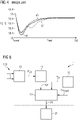
- the diagram also shows two possible response curves.
- a first curve 41 shows the frequency response in the case that the wind power plant does not provide inertial response.
- the grid frequency is not prevented from dropping to an unfavourably low level near 58.2 Hz.
- the grid requirement, indicated by curve 40 states that the frequency may not drop below 58.4 Hz.
- Such a wind power plant would therefore fail to comply with the benchmark frequency response.
- By constructing the wind power plant to provide inertial response e.g. using variable-speed wind turbines
- the frequency response 41 exhibits a second undesirable "dip" in grid frequency from about 59 Hz down to 58.8 Hz.
- this second under-frequency event may be even more severe than the first under-frequency event.
- the inertial response of the wind power plant would have worsened the transient event and would have failed to make a positive contribution towards restoring grid frequency. Severe frequency dips can lead to load shedding or even to blackouts in extreme cases.
- the primary response stage begins with the first few seconds and can last up to a few minutes.
- a grid operator attempts to bring the grid frequency back towards its nominal power with appropriate primary response switching events.
- the grid frequency may have returned to a higher level (59.6 Hz in this example). It is then the task of secondary and tertiary reserve to bring the system back to its nominal frequency, and this can take up to several hours. Similar frequency curves would apply for a different nominal system frequency, for example 50 Hz.
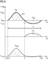
- FIG. 5 is a simplified block diagram of an embodiment of the inventive control arrangement 1, and Figure 6 shows exemplary power curves during an inertial response situation.
- the wind power plant 2 comprises a number of wind turbines 20 and a storage arrangement 21 comprising one or more power storage devices 21.
- the wind power plant 2 can provide inertial response following a grid under-frequency event.
- the control arrangement 1 comprises a monitoring module 10 which is realised to determine the power P 20 stored in the rotating mass 200 of a wind turbine 20 at any one time, for example at the current operating point.
- a computation module 11 is configured to predict the power curve progression PCP if the first power quantity P 20 were to be injected into the grid.
- the power curve progression PCP describes the shape of the power curve during injection (timespan T i ) and subsequent recovery (timespan T r ) towards an operating point for the hypothetical case in which only the stored kinetic energy would provide the power boost in response to a grid under-frequency event.
- the monitoring module 10 is configured to relate the quantity of stored power P 20 (i.e. the magnitude of this "power boost") to the time it would take for the wind turbine to return to the prior operating point, and to predict the shape of the power curve PCP. With this information, it is possible to determine the area of the "power deficit" P def , i.e the area defined by the horizontal axis (the previous power output P exp ) and the PCP curve for all values of output power less than the previous power output P exp .
- the operating point is the initial output power level P exp .
- the stored power P 20 available in the rotating mass 200 and the associated power curve progression PCP can be computed from various inputs 100, for example wind speed, pitch angle, aerodynamic rotor velocity, aerodynamic rotor deceleration rate, generator rotor velocity, etc.
- a second monitoring module 12 keeps track of a second power quantity P 21 available in the storage arrangement 21.
- the available power quantity P 21 can be tracked in real time by individual storage controllers. With suitable communication links between the distributed individual storage controllers and the central monitoring module 10, this can keep track of the total power quantity P 21 available in the storage arrangement 21.
- this is reported to the control arrangement 1, for example as an input signal 13 event to a response management module 13. Knowing the quantity of stored power P 20 available from the kinetic energy of the rotating mass, the power curve progression PCP, and the second power quantity P 21 , the response management module 13 identifies the optimal time instant t 0 at which to commence releasing the second power quantity P 21 so that the combined output power P total of the wind power plant 2 will remain above a pre-defined threshold P limit , in this case the power output P exp immediately preceding the under-frequency event.
- this pre-defined threshold P limit may be defined as a percentage of the previous output level P exp , for example 0.95P exp or 0.99P exp .
- the second power quantity P 21 can be released in a controlled manner by issuing an appropriate setpoint 130 or sequence of setpoints 130.
- the outcome of this controlled power release over phase T i is a combined output power P total that does not exhibit any "deficit", i.e. without any recovery phase as is the case in the prior art and explained in Figure 3 .
- the monitoring module keeps track of the power stored in the available storage device(s). With this information, the response management module can identify the time instant t 0 at which to commence releasing the second power quantity P 21 in order to maintain the combined output power above the pre-defined threshold up until time t end . For example, the response management module 13 may determine the expected rates of increase and decrease in total power output, as well as the shape of the total power curve, in order to determine a favourable time instant t 0 .
- a storage device such as a flywheel may release energy at a slower rate than a battery, for example; one type of storage device may release a large quantity of power in a brief time, compared to another type of storage device which may release its stored power in a slower manner.
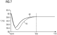
- FIG 7 shows frequency response curves for an exemplary power network as explained in Figure 4 above, with the benchmark curve 40 again showing the expected or required frequency response for this network fed by a wind power plant.
- the curve 43 describes the frequency response when the grid is fed by a wind power plant controlled according to the inventive method. This curve 43 achieves the benchmark minimum frequency, and essentially follows the benchmark curve 40 as the grid frequency returns towards the nominal level. Because of the carefully choreographed release of stored power, there is no "second dip" in grid frequency, which instead follows a favourably smooth progression.
- Figure 8 shows further exemplary power curves for a wind power plant controlled according to the invention.
- the quantity of power P 21 in the storage device arrangement is more than is needed to counteract the negative region of the power curve PCP (the surplus is indicated by the broken line), and the stored power P 21 is released in a controlled manner as described above so that the total combined output power or power boost P total is correspondingly larger (the additional quantity is indicated by the broken line), and also does not drop below the power output level P exp prior to the under-frequency event.
- a wind energy plant can be configured to deploy a grid-forming inverter.
- Figure 9 shows power curves of such a wind energy plant controlled using the prior art approach.
- the stored power P20, P21 is released at a greater rate, and the maximum of the power boost P total is reached sooner.
- the system still shows a pronounced power "dip" P neg and recovery period T r during which the wind energy plant must return towards its previous operating point.
- Figure 10 shows power curves for a wind energy plant with grid-forming functionality, controlled according to the inventive method.
- Release of the stored power P 21 commences at the beginning of the frequency event at time t event , but in such a way as to compensate the negative region of the power curve progression PCP.
- the amplitude of the combined stored power P total is lower in the first seconds compared to the prior art approach shown in Figure 9 , but the wind energy plant avoids the negative effect of a recovery period seen in the prior art approach of Figure 9 , since the output power remains essentially at the pre-event level P exp .
Landscapes
- Engineering & Computer Science (AREA)
- Power Engineering (AREA)
- Life Sciences & Earth Sciences (AREA)
- Sustainable Development (AREA)
- Sustainable Energy (AREA)
- Chemical & Material Sciences (AREA)
- Combustion & Propulsion (AREA)
- Mechanical Engineering (AREA)
- General Engineering & Computer Science (AREA)
- Wind Motors (AREA)
- Control Of Eletrric Generators (AREA)
Priority Applications (7)
| Application Number | Priority Date | Filing Date | Title |
|---|---|---|---|
| EP21171198.1A EP4084257A1 (fr) | 2021-04-29 | 2021-04-29 | Agencement de commande d'une centrale éolienne |
| US18/556,956 US20240209835A1 (en) | 2021-04-29 | 2022-03-22 | Control arrangement of a wind power plant |
| CN202280031661.3A CN117223185A (zh) | 2021-04-29 | 2022-03-22 | 风力发电站的控制装置 |
| EP22717135.2A EP4298706B1 (fr) | 2021-04-29 | 2022-03-22 | Agencement de commande d'une centrale éolienne |
| PCT/EP2022/057480 WO2022228782A1 (fr) | 2021-04-29 | 2022-03-22 | Agencement de commande d'une centrale éolienne |
| ES22717135T ES2995070T3 (en) | 2021-04-29 | 2022-03-22 | Control arrangement of a wind power plant |
| DK22717135.2T DK4298706T3 (da) | 2021-04-29 | 2022-03-22 | Styrearrangement til et vindkraftanlæg |
Applications Claiming Priority (1)
| Application Number | Priority Date | Filing Date | Title |
|---|---|---|---|
| EP21171198.1A EP4084257A1 (fr) | 2021-04-29 | 2021-04-29 | Agencement de commande d'une centrale éolienne |
Publications (1)
| Publication Number | Publication Date |
|---|---|
| EP4084257A1 true EP4084257A1 (fr) | 2022-11-02 |
Family
ID=75746254
Family Applications (2)
| Application Number | Title | Priority Date | Filing Date |
|---|---|---|---|
| EP21171198.1A Ceased EP4084257A1 (fr) | 2021-04-29 | 2021-04-29 | Agencement de commande d'une centrale éolienne |
| EP22717135.2A Active EP4298706B1 (fr) | 2021-04-29 | 2022-03-22 | Agencement de commande d'une centrale éolienne |
Family Applications After (1)
| Application Number | Title | Priority Date | Filing Date |
|---|---|---|---|
| EP22717135.2A Active EP4298706B1 (fr) | 2021-04-29 | 2022-03-22 | Agencement de commande d'une centrale éolienne |
Country Status (6)
| Country | Link |
|---|---|
| US (1) | US20240209835A1 (fr) |
| EP (2) | EP4084257A1 (fr) |
| CN (1) | CN117223185A (fr) |
| DK (1) | DK4298706T3 (fr) |
| ES (1) | ES2995070T3 (fr) |
| WO (1) | WO2022228782A1 (fr) |
Cited By (1)
| Publication number | Priority date | Publication date | Assignee | Title |
|---|---|---|---|---|
| US20240254971A1 (en) * | 2021-06-09 | 2024-08-01 | Siemens Gamesa Renewable Energy Innovation & Technology S.L. | Estimating an upgraded power curve |
Citations (3)
| Publication number | Priority date | Publication date | Assignee | Title |
|---|---|---|---|---|
| US20150381089A1 (en) * | 2013-02-07 | 2015-12-31 | Vestas Wind Systems A/S | Power plant & energy storage system for provision of grid ancillary services |
| US20170298904A1 (en) * | 2016-04-18 | 2017-10-19 | Siemens Aktiengesellschaft | Method for responding to a grid event |
| CN111900742A (zh) * | 2020-07-02 | 2020-11-06 | 武汉大学 | 一种风储系统基于双层协同控制的调频方法 |
Family Cites Families (5)
| Publication number | Priority date | Publication date | Assignee | Title |
|---|---|---|---|---|
| US10756543B2 (en) * | 2012-09-13 | 2020-08-25 | Stem, Inc. | Method and apparatus for stabalizing power on an electrical grid using networked distributed energy storage systems |
| CA2829247C (fr) * | 2012-10-12 | 2017-03-14 | General Electric Company | Systeme et procede de repartition de l'energie eolienne dans un parc eolien |
| US9458828B2 (en) * | 2013-12-09 | 2016-10-04 | Siemens Aktiengesellschaft | Controlling wind power plant with negative power capability to respond to grid frequency instability |
| ES3001116T3 (es) * | 2018-07-09 | 2025-03-04 | Vestas Wind Sys As | Una central eléctrica híbrida y un método para controlar una central eléctrica híbrida |
| WO2020125883A1 (fr) * | 2018-12-21 | 2020-06-25 | Vestas Wind Systems A/S | Centrale électrique hybride et procédé destiné à commander une centrale électrique hybride |
-
2021
- 2021-04-29 EP EP21171198.1A patent/EP4084257A1/fr not_active Ceased
-
2022
- 2022-03-22 US US18/556,956 patent/US20240209835A1/en active Pending
- 2022-03-22 CN CN202280031661.3A patent/CN117223185A/zh active Pending
- 2022-03-22 ES ES22717135T patent/ES2995070T3/es active Active
- 2022-03-22 EP EP22717135.2A patent/EP4298706B1/fr active Active
- 2022-03-22 DK DK22717135.2T patent/DK4298706T3/da active
- 2022-03-22 WO PCT/EP2022/057480 patent/WO2022228782A1/fr not_active Ceased
Patent Citations (3)
| Publication number | Priority date | Publication date | Assignee | Title |
|---|---|---|---|---|
| US20150381089A1 (en) * | 2013-02-07 | 2015-12-31 | Vestas Wind Systems A/S | Power plant & energy storage system for provision of grid ancillary services |
| US20170298904A1 (en) * | 2016-04-18 | 2017-10-19 | Siemens Aktiengesellschaft | Method for responding to a grid event |
| CN111900742A (zh) * | 2020-07-02 | 2020-11-06 | 武汉大学 | 一种风储系统基于双层协同控制的调频方法 |
Non-Patent Citations (1)
| Title |
|---|
| AL KEZ DLZAR ET AL: "A critical evaluation of grid stability and codes, energy storage and smart loads in power systems with wind generation", ENERGY, ELSEVIER, AMSTERDAM, NL, vol. 205, 26 April 2020 (2020-04-26), XP086207866, ISSN: 0360-5442, [retrieved on 20200426], DOI: 10.1016/J.ENERGY.2020.117671 * |
Cited By (1)
| Publication number | Priority date | Publication date | Assignee | Title |
|---|---|---|---|---|
| US20240254971A1 (en) * | 2021-06-09 | 2024-08-01 | Siemens Gamesa Renewable Energy Innovation & Technology S.L. | Estimating an upgraded power curve |
Also Published As
| Publication number | Publication date |
|---|---|
| EP4298706A1 (fr) | 2024-01-03 |
| ES2995070T3 (en) | 2025-02-06 |
| CN117223185A (zh) | 2023-12-12 |
| US20240209835A1 (en) | 2024-06-27 |
| EP4298706B1 (fr) | 2024-07-10 |
| DK4298706T3 (da) | 2024-09-16 |
| WO2022228782A1 (fr) | 2022-11-03 |
Similar Documents
| Publication | Publication Date | Title |
|---|---|---|
| CN112636374B (zh) | 用于风电场站的一次调频和虚拟惯量响应控制方法及装置 | |
| US9690267B2 (en) | Selective droop response control for a wind turbine power plant | |
| EP2532888B1 (fr) | Agencement de génération d'un signal de commande pour contrôler la sortie d'alimentation d'un système de génération de puissance | |
| CN104271942B (zh) | 用于利用调度算法运行风力发电系统的电力系统和方法 | |
| JP4551921B2 (ja) | 蓄電システム併設型風力発電システム | |
| CN103097726B (zh) | 具有减小的功率波动的风电生产 | |
| CN104321944B (zh) | 用于协调传统发电厂与风力发电厂之间的频率控制特性的方法 | |
| EP4045792B1 (fr) | Commande de système d'alimentation auxiliaire dans des centrales électriques hybrides | |
| US11929638B2 (en) | Full DC voltage power backup system for wind turbine | |
| US20230223760A1 (en) | Hybrid power plant fast frequency response | |
| EP4298706B1 (fr) | Agencement de commande d'une centrale éolienne | |
| EP2280167A2 (fr) | Système de génération d'éolienne d'un type fourni avec un système de stockage d'alimentation | |
| Conte et al. | Optimal control of a wind farm-bess unit to combine synthetic inertia and fast reserve | |
| Rapizza et al. | Droop control of wind turbines to provide upward support in frequency regulation | |
| Li et al. | Model predictive control based power scheduling of offshore wind farm for primary frequency support considering turbulent wind uncertainty | |
| Lyu et al. | An active power regulation strategy for wind farm considering wake effect | |
| US12372059B2 (en) | Wind energy plant | |
| Islam et al. | A Coordinated Wind Deloading Estimation Approach for Frequency Control of a Renewable Integrated Grid | |
| Hafiz et al. | Optimal inertial support from the variable speed wind turbines using particle swarm optimization | |
| Li et al. | Delayed Complementation Control for Wind Turbines Participating in Primary Frequency Regulation | |
| EP4454091A1 (fr) | Système et procédé de commande pour une centrale électrique renouvelable |
Legal Events
| Date | Code | Title | Description |
|---|---|---|---|
| PUAI | Public reference made under article 153(3) epc to a published international application that has entered the european phase |
Free format text: ORIGINAL CODE: 0009012 |
|
| STAA | Information on the status of an ep patent application or granted ep patent |
Free format text: STATUS: THE APPLICATION HAS BEEN PUBLISHED |
|
| AK | Designated contracting states |
Kind code of ref document: A1 Designated state(s): AL AT BE BG CH CY CZ DE DK EE ES FI FR GB GR HR HU IE IS IT LI LT LU LV MC MK MT NL NO PL PT RO RS SE SI SK SM TR |
|
| STAA | Information on the status of an ep patent application or granted ep patent |
Free format text: STATUS: THE APPLICATION HAS BEEN REFUSED |
|
| 18R | Application refused |
Effective date: 20221120 |