EP4084288B1 - Module de bobine pour une machine électrique - Google Patents
Module de bobine pour une machine électrique Download PDFInfo
- Publication number
- EP4084288B1 EP4084288B1 EP21170784.9A EP21170784A EP4084288B1 EP 4084288 B1 EP4084288 B1 EP 4084288B1 EP 21170784 A EP21170784 A EP 21170784A EP 4084288 B1 EP4084288 B1 EP 4084288B1
- Authority
- EP
- European Patent Office
- Prior art keywords
- coil
- ceramic
- windings
- delimitation
- disc
- Prior art date
- Legal status (The legal status is an assumption and is not a legal conclusion. Google has not performed a legal analysis and makes no representation as to the accuracy of the status listed.)
- Active
Links
Images






Classifications
-
- H—ELECTRICITY
- H02—GENERATION; CONVERSION OR DISTRIBUTION OF ELECTRIC POWER
- H02K—DYNAMO-ELECTRIC MACHINES
- H02K1/00—Details of the magnetic circuit
- H02K1/04—Details of the magnetic circuit characterised by the material used for insulating the magnetic circuit or parts thereof
-
- H—ELECTRICITY
- H02—GENERATION; CONVERSION OR DISTRIBUTION OF ELECTRIC POWER
- H02K—DYNAMO-ELECTRIC MACHINES
- H02K21/00—Synchronous motors having permanent magnets; Synchronous generators having permanent magnets
- H02K21/12—Synchronous motors having permanent magnets; Synchronous generators having permanent magnets with stationary armatures and rotating magnets
- H02K21/24—Synchronous motors having permanent magnets; Synchronous generators having permanent magnets with stationary armatures and rotating magnets with magnets axially facing the armatures, e.g. hub-type cycle dynamos
-
- H—ELECTRICITY
- H02—GENERATION; CONVERSION OR DISTRIBUTION OF ELECTRIC POWER
- H02K—DYNAMO-ELECTRIC MACHINES
- H02K3/00—Details of windings
- H02K3/46—Fastening of windings on the stator or rotor structure
- H02K3/47—Air-gap windings, i.e. iron-free windings
-
- H—ELECTRICITY
- H02—GENERATION; CONVERSION OR DISTRIBUTION OF ELECTRIC POWER
- H02K—DYNAMO-ELECTRIC MACHINES
- H02K7/00—Arrangements for handling mechanical energy structurally associated with dynamo-electric machines, e.g. structural association with mechanical driving motors or auxiliary dynamo-electric machines
- H02K7/003—Couplings; Details of shafts
-
- H—ELECTRICITY
- H02—GENERATION; CONVERSION OR DISTRIBUTION OF ELECTRIC POWER
- H02K—DYNAMO-ELECTRIC MACHINES
- H02K7/00—Arrangements for handling mechanical energy structurally associated with dynamo-electric machines, e.g. structural association with mechanical driving motors or auxiliary dynamo-electric machines
- H02K7/006—Structural association of a motor or generator with the drive train of a motor vehicle
-
- H—ELECTRICITY
- H02—GENERATION; CONVERSION OR DISTRIBUTION OF ELECTRIC POWER
- H02K—DYNAMO-ELECTRIC MACHINES
- H02K7/00—Arrangements for handling mechanical energy structurally associated with dynamo-electric machines, e.g. structural association with mechanical driving motors or auxiliary dynamo-electric machines
- H02K7/14—Structural association with mechanical loads, e.g. with hand-held machine tools or fans
-
- H—ELECTRICITY
- H02—GENERATION; CONVERSION OR DISTRIBUTION OF ELECTRIC POWER
- H02K—DYNAMO-ELECTRIC MACHINES
- H02K9/00—Arrangements for cooling or ventilating
- H02K9/19—Arrangements for cooling or ventilating for machines with closed casing and closed-circuit cooling using a liquid cooling medium, e.g. oil
-
- H—ELECTRICITY
- H02—GENERATION; CONVERSION OR DISTRIBUTION OF ELECTRIC POWER
- H02K—DYNAMO-ELECTRIC MACHINES
- H02K9/00—Arrangements for cooling or ventilating
- H02K9/22—Arrangements for cooling or ventilating by solid heat conducting material embedded in, or arranged in contact with, the stator or rotor, e.g. heat bridges
-
- H—ELECTRICITY
- H02—GENERATION; CONVERSION OR DISTRIBUTION OF ELECTRIC POWER
- H02K—DYNAMO-ELECTRIC MACHINES
- H02K2213/00—Specific aspects, not otherwise provided for and not covered by codes H02K2201/00 - H02K2211/00
- H02K2213/03—Machines characterised by numerical values, ranges, mathematical expressions or similar information
-
- H—ELECTRICITY
- H02—GENERATION; CONVERSION OR DISTRIBUTION OF ELECTRIC POWER
- H02K—DYNAMO-ELECTRIC MACHINES
- H02K2213/00—Specific aspects, not otherwise provided for and not covered by codes H02K2201/00 - H02K2211/00
- H02K2213/12—Machines characterised by the modularity of some components
Definitions
- the present invention relates to a coil module for an electrical machine, an electrical machine, a vehicle and/or a machine tool.
- the present invention is therefore based on the object of proposing a coil module for an electrical machine with which these disadvantages can be overcome and a compact design with a reduced space requirement can be implemented.
- a further object on which the invention is based is to provide reliable, effective, space-saving and/or weight-saving cooling of the electrical machine and/or to increase the service life of the electrical machine.
- the GB 2485185A relates to an electrical machine with an axial gap.
- the CN 204 559 345 U relates to a hub motor with a stator and two rotor discs, the windings of which are applied to printed circuit boards.
- the U.S. 2010/001610 A1 relates to a coil assembly for a rotating electric machine with an axial gap.
- the CA 2 262 732 A1 relates to a rotating electrical machine.
- an electrical machine is to be understood as a device that converts electrical energy into mechanical work or vice versa.
- the term "electrical machine” can be understood in particular as an electric power machine or an electric motor or an electric motor or an electric generator or electric generator.
- a coil module for an electrical machine has at least two coil disks.
- Each coil disk in turn has a coil carrier made of an electrically insulating material and a large number of individual windings made of an electrically conductive material, typically in wire form.
- the windings are embedded in the coil carrier, for example cast.
- the windings are arranged around a center point of the at least one coil disk on the at least one coil disk.
- Each of the windings has two active regions extending radially from the midpoint and two passive regions extending tangentially at its radially outer and inner edges.
- the active areas of different windings do not overlap each other, but each passive area of one of the windings partially overlaps the corresponding passive areas of the two immediately adjacent windings.
- a thickness of the respective winding in the axial direction is greater than in the passive areas of the respective winding.
- the active areas can be understood to mean the areas of the windings that are suitable for contributing to the torque of the electrical machine and/or are located in the magnetic field of at least one adjacent magnet module of the electrical machine. Accordingly, the passive areas of the windings are not suitable for contributing to the torque of the electric machine and/or are not in the magnetic field of an adjacent magnet module of the electric machine.
- the term “thickness of the respective winding in the axial direction” or “thickness in the axial direction” of the winding is to be understood as meaning the thickness of the winding measured in the axial direction.
- the “width in the tangential or radial direction” of the winding is to be understood as meaning the width of the winding measured in the tangential or radial direction.
- an amount of electrically conductive material, preferably copper, in the passive areas is typically twice that in the active areas.
- the thickness in the axial direction in the cross section is greater in the active areas than in the passive areas, so that a compact structure is ensured.
- An electrically insulating material is to be understood as meaning a material with an electrical conductivity of less than 10 ⁇ 8 S/m at a temperature of 25°C. Any material whose electrical conductivity is greater than 10 6 S/m at a temperature of 25° C. is to be understood as an electrically conductive material.
- the radial direction is to be understood as the direction running from the center in a straight line to the edge, and the tangential direction is accordingly a direction running at right angles to the radial direction.
- the passive areas can be understood to mean those areas of the windings which do not run radially and which connect the two active areas of the respective individual winding to one another. However, the passive areas do not have to be exactly tangential.
- the passive areas can also preferably have short, radially running areas which adjoin the active areas and in which, for example, a change in cross section takes place.
- a top view should be understood as a view along a normal vector of the at least one coil disk, and a side view should be understood as a position angled by 90° compared to the top view.
- the normal vector should start from the area in which the length and width of the at least one coil disk are greater than a thickness of the at least one coil disk.
- windings In the electrical machine, the normal vector is thus parallel to the axis of rotation.
- the windings also referred to as coils, are preferably present as coreless or iron-core windings.
- the term “coil carrier” is to be understood in particular as meaning a carrier for windings or coils, which typically mechanically connects the windings and preferably consists of an epoxy resin or other temperature-resistant plastic.
- the term “coil disk” means a corresponding ring fixed by the coil carrier with the coils or windings, while the term “coil module” is intended to mean a complete built-in part with at least one coil disk, but typically two or more coil disks.
- the multiplicity of individual windings can, for example, be cast into the material of the coil carrier, preferably epoxy resin, and thus form the coil disk.
- a ratio of the thickness of the respective winding in the passive areas to the thickness in the active areas can be less than 1.
- the ratio is preferably greater than or equal to 0.3 and less than 1, particularly preferably exactly 0.5 in the case of outer passive areas, in order to utilize the larger installation space and when considering the coil disk, a uniform relative thickness with the active area of equal to 1 generate.
- the shape of the cross-sectional area of the respective winding changes during a transition from an active region to a passive region.
- a surface area of the cross-sectional area remains the same and a filling factor is maximum, which can occur with pressing, for example, but the changed shape allows the magnetic field lines to flow through more material and thus the drive can be made more efficient.
- the installation space available for the electrically conductive material can be used in the electrical machine with the magnet distance remaining the same, thus increasing performance and efficiency accordingly.
- all active areas of different windings are arranged in and/or intersect a single plane in side view.
- This plane can be orthogonal to the axial direction of the coil disk or the electrical machine.
- the active areas e.g., in the fanned-out embodiment, may have a varying thickness such that their top and/or bottom surfaces may not be parallel to the plane.
- the active regions are preferably formed in such a way that they intersect the plane. A single active area or a small number of active areas can be excluded from this, in which or in which the web described herein is formed, for example.
- the active areas of the various windings can all be arranged at the same height in side view in the direction along the normal vector of the coil disc, so that, for example, no active area protrudes with respect to the other active areas.
- a single active area or a small number of active areas can be excluded from this, in which or in which the web described herein is formed, for example.
- the arrangement in a single plane ensures that all active areas are equally located in the magnetic field of a magnetic module.
- the web described herein can be arranged in this area.
- the thickness in the axial direction of the active areas of the respective windings preferably decreases in the radial direction outwards. Furthermore, the width in the tangential direction of the active areas of the respective windings increases in the radial direction outwards.
- the active areas are fanned out towards the outside.
- this fanning out does not have to be present in the entire active areas of the windings.
- the active areas adjacent to the passive areas may have respective transitions that are exempt from this fanning out.
- the cross-sectional area of the active regions remains constant along the radial direction.
- the windings are formed from a fine strand of several wires that are electrically insulated from one another, with the wires that are electrically insulated from one another having a wire diameter of less than or equal to 0.1 mm.
- a plurality of strands provided with an electrically insulating coating can ensure sufficient flexibility of the winding formed from the wire during production and also achieve sufficiently high electrical conductivity.
- a number of windings preferably corresponds to an integer multiple of 3, so that the windings enable three-phase operation.
- a total of three strands of different phases are thus formed from the windings.
- all active areas of the windings of all phases are in a single plane when viewed from the side, while the passive areas of the different phases are distributed over two planes.
- the passive areas of two phases are each in one level and the passive areas of the third phase undergo an additional level change.
- the two planes are typically different or offset from each other, but parallel to each other.
- the coil disk can be designed in such a way that an inner passive area and an outer passive area of one of the windings differ in terms of their thickness in the axial direction.
- the inner passive area is arranged at a smaller distance from the center point of the coil disk and the coil module than the outer passive area.
- the thickness of the outer passive area of one of the windings is typically chosen such that a ratio of the thickness of this area to the thickness of the active areas is less than or equal to 0.5.
- the inner passive area can be provided that the ratio of the thickness of this inner passive area to the thickness of the active areas is less than 1.
- the cooling surface can be extended from the active areas to the outer passive areas.
- the invention also relates to an electrical machine with a bearing and a shaft guided in the bearing, at least one magnet module with a plurality of permanent magnets and at least one coil module disclosed in this document being arranged concentrically along the shaft.
- the electric machine such as an electric motor or electric motor or an electric generator or electric generator, has a bearing and a shaft guided in the bearing. At least one magnet module with a plurality of permanent magnets and at least one coil module with the properties described above are arranged concentrically along the shaft, the magnet module being attached to the shaft and the coil module being connected to a housing. Due to the high packing density of the windings, a particularly advantageous efficiency and power density is achieved during operation of the electrical machine.
- the at least one coil module can have a film made of an electrically insulating material stuck to it, at least on its side facing the magnet module, in order to prevent the passage of liquid and to enable the formation of cooling channels.
- the film can also be applied by another connection such as a welded connection as a material connection or a non-positive connection, for example by a screwed-on ring.
- the at least one coil module can have at least two coil disks connected to one another and a cooling channel formed by a cavity between the two coil disks.
- the cooling channel can also be formed and delimited by the coil disk or the coil module and the foil.
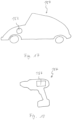
- the invention also relates to a vehicle or a machine tool or a tool with an electrical machine disclosed in this document.
- a further coil module, a further electrical machine and/or a further vehicle or a further machine tool are disclosed below.
- the coil module described below contains a number of features that are also disclosed in connection with the coil module described above, the technical effects, advantages and explanations described above also apply to corresponding features described below.
- the coil module described below can preferably have any of the features described above in connection with the coil module.
- the coil module has a first coil disk with at least one winding made of an electrically conductive material and a second coil disk with at least one winding made of an electrically conductive material.
- the first coil disk and/or the second coil disk have/have a substantially annular recess.
- the first coil disk and the second coil disk are also attached to one another in such a way that a substantially annular cooling channel for a coolant is formed between the first coil disk and the second coil disk through the annular recesses/recess.
- the coil module, the first coil disk, the second coil disk and the windings of the first and second coil disks can be designed as disclosed above.
- An essentially annular recess can be understood to mean a recess which extends essentially around the entire circumference of the reel disc.
- the statement “essentially” means that the recess has, for example, one (or more) webs, described in more detail below, which interrupt the essentially annular recess.
- the substantially annular recess may extend around a center point of the reel disk and may not be located at the center point of the reel disk.
- the center point of the coil disk is to be understood as meaning the point on the coil disk through which the axis of rotation of the shaft or of the electrical machine runs.
- the radially outer and/or the radially inner edge of the substantially annular recess may be circular in a plan view (i.e. a view orthogonal to the longitudinal and width directions) of the reel disc.
- the radially outer and radially inner edge of the recess in this case designate the transition from the essentially flat surface of the coil disk to the essentially ring-shaped recess.
- the shape of the outer and/or inner edge can also deviate from an exact circular shape.
- the outer and/or inner edge can be wavy.
- the outer and/or inner edge can also have a polygonal shape.
- the recess can have a rectangular cross-section with two opposite
- the recess can also have a trapezoidal cross section, in which the distance between the opposite side surfaces and the bottom surfaces decreases.
- the recess can also have a circular arc-shaped or curved cross section.
- the ring-shaped recess can be understood to mean a substantially ring-shaped indentation in the coil disk.
- the coil disc can have a smaller thickness in the area of the essentially ring-shaped recess than in areas outside of the ring-shaped recess.
- the coil disk is preferably made by potting the at least one winding in the electrically insulating material such as epoxy resin. To do this, the windings can be placed in a mold that is then filled with the electrically insulating material.
- the essentially ring-shaped recess can then be produced in a pressing process. For example by means of a substantially ring-shaped mold or a punch.
- the form in which the at least one winding is inserted may have projections that keep the gaps between the active areas of the windings free, so that the coil disk in a substantially annular area in which the active areas of the windings are located between the active areas has air gaps.
- the coil disk with these gaps can be particularly suitable for air cooling of the electrical machine, with another form of cooling being preferred, for example by means of a coolant (e.g. water-glycol mixture).
- these protrusions in the mold can preferably be omitted, so that the distances between the active areas can be very small and no gap remains between the active areas after molding.
- the essentially ring-shaped recess can also be produced by means of other methods.
- the mold itself into which the electrically insulating material is inserted can define the recess, so that no subsequent pressing process is required.
- the essentially ring-shaped recess can also be produced, for example, by milling.
- Such a substantially annular recess may be provided in one of the first and/or second reel disc.
- both in the first and in the second coil disc each provided a substantially annular recess.
- a disk is to be understood as a body whose length and width or diameter are significantly greater, e.g. by a factor of 10, than its thickness.
- the sides of the disc are to be understood as meaning the sides of the body which are parallel to the plane spanned by length and width, i.e. orthogonal to the axial direction of the electric machine.
- the substantially annular recess is provided in one of the sides of the reel disc.
- the coil disk can also have a substantially ring-shaped recess on both sides.
- the first and second coil disks may be attached to each other such that one of the two sides of the first coil disk abuts one of the two sides of the second coil disk, not excluding the interposition of a sealing layer.
- the first and second coil disks can be glued to one another, with the adhesive being able to seal off the coolant channel from the environment at the same time, for example.
- the sides of the first and second coil disks that abut the other coil disk are each called the inner side.
- the sides of the first and second reel discs that face outward and do not abut the other reel disc are called outer sides. It can therefore be understood that the substantially annular recess is provided on the inner side of the first reel disc and/or the inner side of the second reel disc.
- the recesses of the first and second reel discs preferably have identical shapes and are preferably arranged such that they lie exactly opposite and/or overlap one another.
- the recess in the first coil disk it is also possible for the recess in the first coil disk to have a different shape than the recess in the second coil disk and/or for them to be offset from one another when the coil module is in the assembled state.
- the essentially annular cooling channel can be understood to mean a space delimited by the first and second coil disks, which is delimited on the one hand by the wall of the recess in the first or second coil disk and on the other hand by the inner side of the second coil disk.
- the essentially ring-shaped cooling channel is delimited by two recesses provided in the first coil disk and the second coil disk.
- the essentially annular cooling channel does not have to be completely delimited. This means that the essentially ring-shaped cooling channel can have, for example, an inlet opening and/or an outlet opening, by means of which coolant can get into the cooling channel and/or be discharged from it.
- This cooling duct offers the advantage that a coolant can be brought very close to the windings, so that the electric machine can be cooled very effectively. At the same time, this cooling structure does not require any additional components for conducting the coolant, so this cooling structure saves space and weight. In addition, this cooling structure is also very robust and not prone to failure.
- the coolant is preferably a water-based coolant, more preferably a water-glycol mixture.
- transformer oil can also be used as a coolant.
- the coil module described herein can also be air-cooled.
- the first coil disk and/or the second coil disk preferably have/have an inlet opening in the region of the recess in order to conduct coolant into the essentially annular cooling channel.
- the first coil disk and/or the second coil disk have/have an outlet opening in the area of the recess in order to direct coolant outwards from the essentially ring-shaped cooling channel.
- the inlet opening and/or outlet openings can be provided, for example, in the radially outer side surface of the recess.
- the inlet port is provided in the side surface of the recess of the first reel disk and the outlet port is in the side surface of the second recess, or vice versa.
- An inlet channel can extend in the first spool disk starting from the inlet opening and an outlet channel can extend in the second spool disk starting from the outlet opening.
- the inlet channel and the outlet channel can each extend radially outwards from the inlet or outlet opening.
- the inlet channel can be formed as a recess in the first spool disk and the outlet channel can be formed as a recess in the second spool disk.
- an intake hole and/or an intake through hole may be provided in the first and second spool discs to direct the coolant into the intake port.
- an exhaust hole and/or an exhaust through hole in the spool disk may be provided in the first and second spool disks to direct the coolant out of the exhaust port.
- the inlet duct and/or the outlet duct preferably extend in an outer passive area of a winding which does not or only partially covers the outer passive areas of the immediately adjacent windings.
- the inlet and/or outlet channel is arranged in an area in which the thickness of the windings is as small as possible is. This allows a space-saving arrangement.
- the inlet and outlet openings and the inlet and outlet channels can be provided in only one of the two spool disks or in both spool disks.
- the coil spacer can also have inlet and outlet holes.
- the inlet holes of the various coil modules and the coil spacers arranged between them overlap.
- the outlet holes of the various coil modules and the coil spacers arranged between them overlap. In other words, all of the inlet and outlet holes can each lie in one line.
- the inlet and outlet holes can be omitted in the case of the coil disk or coil spacer located at one end of the electrical machine, viewed in the axial direction.
- the coolant can be conducted into the individual coil modules through the inlet and outlet holes. In this way, the different coil modules can be connected to one another in parallel with regard to the coolant flow.
- a first connecting line between the inlet opening and the center point of the spool disk and a second connecting line between the outlet opening and the center point of the spool disk can enclose an angle in a plan view of the spool disk which is preferably smaller than 30°, more preferably smaller than 20°, even further is preferably less than 10°.
- the first coil disk and/or the second coil disk preferably has a web in the recess between the inlet opening and the outlet opening, which is designed such that the essentially ring-shaped cooling channel has a partition wall between the inlet opening and the outlet opening. It should be understood that the ridge between the shortest connection of the inlet port and the outlet port is located in the recess to force the coolant to flow around almost the entire circumference of the spool disc.
- the web can be understood as an interruption of the recess. In other words, it can be understood that the web runs from the radially inner edge of the recess to the radially outer edge of the recess.
- the web can, for example, run radially from the inner edge of the recess to the outer edge of the recess. Alternatively, the web can form an angle to the radial direction.
- the web can have an upper side which lies above the bottom surface of the recess, preferably in the same plane as the rest of the inner side of the reel disk. In this case, the web is preferably designed to be as narrow as possible, so that it continues to represent an effective blockage for the coolant.
- the first connecting line between the inlet opening and the center point of the spool disk and the second connecting line between the outlet opening and the center point of the spool disk also enclose an angle that is less than 30°. Due to the web between the inlet and outlet openings, the coolant cannot take the "short way" between the inlet and outlet openings and is forced to flow around the remaining, significantly larger circular arc section of the cooling channel.
- This web forms a barrier for the coolant in the cooling channel. This web therefore ensures that the coolant flows through all relevant areas of the first and second coil disks and thus cools all relevant areas of the first and second coil disks.
- the first and second coil disks each have a recess and a ridge.
- the web of the first coil disk and the web of the second coil disk lie on top of one another, although it is not excluded that an adhesive and/or sealing layer is arranged between them, with the adhesive being able to represent the seal at the same time.
- the first coil disk and the second coil disk each have: at least one coil carrier made of an electrically insulating material and a large number of individual windings made of an electrically conductive material, which are arranged on the at least one coil disk around a center point of the at least one coil disk.
- each of the windings has two active regions running radially from the center and two passive regions running tangentially on its radially outer and inner edge.
- the active areas of different windings do not overlap one another, but each passive area of one of the windings partially overlaps the corresponding passive areas of the two immediately adjacent windings.
- the respective windings in the active areas have a greater thickness in the axial direction in cross-section than in the passive areas.
- the recesses/recesses are/is arranged at least in the area of the radially extending active areas, preferably also in the area of the radially outer passive areas.
- the recesses/recesses can also be provided at least partially in the passive areas, preferably in the radially outer passive areas.
- the radially outer passive areas can have a greater width in the radial direction than the radially inner passive areas, so that it is possible to form the radially outer passive areas with a smaller thickness in the axial direction. It is also possible that not all of the passive areas of the different windings cover the passive areas of the immediately adjacent windings. In this way, for example, there can also be space for the recess in the passive areas.
- the thickness in the axial direction of the active areas of the respective winding of the first and/or second coil disk decreases outwards in the radial direction. Furthermore, the width in the tangential direction of the active areas of the respective winding of the first and/or second coil disk increases outwards in the radial direction.
- This structure is also referred to as "fan out" of the active areas.
- the thickness in the axial direction does not have to decrease outwards along the entire length of the active areas and the width in the tangential direction does not have to increase outwards along the entire length of the active areas.
- the active ones are preferred Areas fanned out along at least 70%, preferably at least 90%, of their length.
- a further advantage of this fanning out is that the distance or gap between an active area of a winding and the active areas of the immediately adjacent windings can be reduced.
- a resulting advantage is that when the recess is in the active areas of the winding or windings, the bottom surface of the recess is sealed by the coil disc itself. This means that there is no gap between the active areas of the winding or windings that would have to be additionally sealed.
- the coil disc is thus not only self-supporting but also self-sealing.
- the foil described above can be dispensed with, so that the coil module has a smaller thickness overall in the axial direction.
- the magnet module in the electric machine can be brought closer to the winding or windings, which in turn increases the performance and/or the efficiency of the electric machine.
- the distance between an active area of a winding and the active areas of the immediately adjacent windings is preferably a few micrometers.
- a depth in the axial direction of the recess preferably increases outwards in the radial direction.
- the depth in the axial direction of the recess is to be understood as the depth of the recess measured in the axial direction, eg the difference between the lowest point (eg the bottom surface) of the recess and a plane defined by the inner side of the reel disk.
- the fact that the depth in the axial direction of the recess increases outwards in the radial direction can be understood to mean that an inner, radial, essentially ring-shaped area of the recess has a smaller depth than an essentially ring-shaped area of the recess that is further to the outside.
- the depth can increase continuously (i.e. steadily) or in steps (i.e. discontinuously) from the inside to the outside.
- the depth can also increase linearly or non-linearly from the inside to the outside.
- This geometry of the recess is also called "V-Cooling" geometry.
- a ratio of the thickness of the respective winding in the passive areas to the thickness in the active areas is preferably less than 1.
- the ratio of the thickness of the respective winding in the passive areas to the thickness in the active areas is greater than or equal to 0.3 and less than 1.
- the added thickness in the axial direction of two immediately adjacent windings in the area of the overlapping passive areas is greater than the thickness in the axial direction of each of the two immediately adjacent windings in the active areas.
- the added axial thickness of two immediately adjacent windings in the area of the overlapping inner passive areas and in the area of the overlapping outer passive areas is greater than the axial thickness of each of the two immediately adjacent windings in the active areas.
- the added axial thickness of two immediately adjacent windings in the area of the overlapping inner passive regions may be greater than the axial thickness of each of the two immediately adjacent windings in the active regions.
- the added thickness in the axial direction of the two immediately adjacent windings in the area of the overlapping outer passive regions can be smaller than the thickness in the axial direction each of the two immediately adjacent windings in the active areas.
- an active area or a few active areas can lie in the area of the ridge described herein and thus have a greater thickness than the other active areas.
- the total thickness in the axial direction of two immediately adjacent windings in the area of the overlapping passive areas is the sum of the respective thickness in the axial direction of the respective passive areas of the respective windings, with the thickness of the respective passive areas being measured in an area in which the passive areas of the immediately adjacent windings overlap.
- the total thickness in the axial direction of the two immediately adjacent windings can also be greater than the thickness in the axial direction of each of the two immediately adjacent windings in the active areas only in the area of the radially inner passive areas.
- the active areas and optionally the outer passive areas preferably take up less space overall in the axial direction than the passive areas.
- the recess in the coil disks in the area of the active areas and, if applicable, the outer passive areas.
- a ratio of the total thickness in the axial direction of two immediately adjacent windings in the area of the overlapping passive areas to the maximum thickness in the axial direction of each of the two immediately adjacent windings in the active areas is preferably greater than 1.
- the shape of the cross-sectional area of the respective winding preferably changes during a transition from an active area to a passive area.
- all active areas of different windings are arranged in a single plane in side view.
- the windings are preferably formed from a fine strand of several wires which are electrically insulated from one another and have a wire diameter of less than or equal to 0.1 mm.
- a number of windings preferably corresponds to an integer multiple of 3, so that the windings enable three-phase operation.
- An inner passive area and an outer passive area of one of the windings preferably differ in their thickness in the axial direction.
- the thickness of the outer passive area of one of the windings is preferably chosen such that a ratio of the thickness of this area to the thickness of the active areas is less than or equal to 0.5.
- the invention also relates to an electrical machine with a bearing and a shaft guided in the bearing, at least one magnet module with a plurality of permanent magnets and at least one coil module disclosed in this document being arranged concentrically along the shaft.
- the electrical machine preferably has at least one coil module, preferably at least one coil module and a maximum of six coil modules, particularly preferably at least one coil module and a maximum of three coil modules.
- the electrical machine preferably has one more magnet module than coil modules.
- the invention also relates to a vehicle or a machine tool with an electrical machine disclosed within the scope of this document.
- the coil module described below contains a number of features that are also disclosed in connection with the coil module described above, the technical effects, advantages and explanations described above also apply to corresponding features described below.
- the coil module described below can preferably have any of the features described above in connection with the coil module.
- the coil module according to the invention for an electrical machine has a first coil disk with a first coil carrier made of an electrically insulating material, at least one winding made of an electrically conductive material embedded in the first coil carrier and a first ceramic boundary. Furthermore, the coil module has a second coil disk a second coil support made of an electrically insulating material, at least one winding made of an electrically conductive material embedded in the second coil support, and a second ceramic boundary.
- the first coil disk and the second coil disk are designed and attached to one another in such a way that a substantially annular cooling channel for a coolant is formed between the first coil disk and the second coil disk.
- the first ceramic boundary and the second ceramic boundary each at least partially form an inner wall of the essentially annular cooling channel.
- the cooling channel preferably has an axial extent of between 1 mm and 2 mm.
- the coil module, the first coil disk, the second coil disk and the windings of the first and second coil disks can be designed as disclosed above.
- the first coil disk and the second coil disk are designed in such a way that when they are assembled and/or in contact with one another, they form a substantially annular cooling channel between them.
- the cooling channel can be a cavity between the first coil disk and the second coil disk, which is suitable and/or designed to transport a coolant, as a result of which heat is effectively transported away from the first coil disk and/or the second coil disk can.
- the first and/or second coil carrier has/has an essentially annular recess which forms the cooling channel when the first and second coil disks are in the assembled state.
- the first and second coil carriers can, for example, each have a raised and/or thicker radially inner area which rests against one another when the first and second coil disks are in the assembled state.
- the radially outer areas of the first and second coil carriers can be spaced apart from one another when the first and second coil disks are in the assembled state and thus form the essentially annular cooling channel. Seen in the radial direction, this coolant channel can be delimited outwards by a further delimitation, for example the radially outer ceramic delimitation described herein and/or the coil carrier ring.
- the first ceramic delimitation can be understood to mean a structure made of ceramic material of the first coil disk, which at least partially forms and/or lines the inner wall of the essentially ring-shaped cooling channel.
- the second ceramic boundary can be understood to mean a structure made of ceramic material of the second coil disk, which at least partially defines the inner wall of the essentially annular cooling channel forms and/or lines.
- the first ceramic delimitation can delimit the interior of the essentially ring-shaped cooling channel from the first coil carrier and the second ceramic demarcation may demarcate the interior of the substantially annular cooling passage from the second bobbin.
- the ceramic borders can be provided in different ways.
- the ceramic boundaries are provided in the form of disks of ceramic material which are placed between the coil disks on the first and second coil supports, respectively.
- the first and second ceramic demarcations may be two separate structures that are bonded, e.g., bonded, together upon assembly of the first coil disk and the second coil disk to form the interior wall of the substantially annular cooling passage.
- the first and second ceramic boundaries may also be formed in one piece and/or integrally with each other.
- the ceramic contained in the ceramic boundary is vapour-tight or essentially vapour-tight.
- the ceramic boundaries therefore do not absorb any water and/or prevent water from the cooling channel from accumulating in the insulating material of the coil carrier.
- ceramics have a high resistance to media and/or chemicals.
- the ceramic of the ceramic boundary has a significantly higher thermal conductivity than the material of the coil carrier. For example, the thermal conductivity of ceramics is around 100 times higher than that of plastic.
- the ceramic barrier can provide better heat dissipation through the coolant in the cooling channel.
- Ceramic is also electrically insulating.
- the first and second ceramic barriers can therefore prevent the coolant in the cooling channel from contacting the first and second bobbins and concentrating in the material of the first and second bobbins.
- Such enrichment of the coolant can lead to the material of the coil carrier losing its insulating effect, for example if the coolant contains water.
- the ceramic delimitations By providing the ceramic delimitations, a water-based coolant can therefore be used and it can be ensured that the coil carriers retain their insulating effect maintained for a long time.
- Aqueous coolants are due to the high Heat capacity and the good heat conduction of water are advantageous. Therefore, the cooling of the coil disk of the electrical machine can be improved and the service life of the electrical machine can be increased at the same time. At the same time, the dissipation of heat from the coil discs is also improved.
- the ceramic boundary offers the advantage that the thickness of the electrically insulating material of the coil carrier can be reduced, which in turn improves the cooling capacity and the efficiency of the electrical machine.
- the ceramic of the ceramic boundaries is a mechanically very strong material.
- the ceramic boundaries can therefore also ensure or improve the mechanical strength and/or stability of the reel disks.
- the mechanical strength of the coil disks can prevent the coil disks from expanding in the axial direction due to the internal pressure of the coolant and the electromagnetic forces acting in the coil module, so that the rotor would possibly rub against the coil module. In this way, the focus when selecting the material for the coil carrier can be placed on heat conduction and heat resistance, while the mechanical strength of the coil disks can be guaranteed by the ceramic boundary.
- the first and/or second ceramic boundary preferably has/has an aluminum-based and/or silicon-based ceramic, preferably a material from the group consisting of aluminum oxide, aluminum nitride, silicon carbide and silicon nitride.
- these ceramic materials are suitable for use as a ceramic boundary.
- Aluminum oxide is also widely used and readily available, among other things, and is therefore particularly suitable.
- the first ceramic delimitation forms the inner wall of the essentially annular cooling duct in the entire radial area of the essentially annular cooling duct; and/or the second ceramic boundary forms the inner wall of the essentially annular cooling duct in the entire radial area of the essentially annular cooling duct.
- the first ceramic delimitation and/or the second ceramic delimitation has a first or second ceramic disk arranged on the first coil carrier or the second coil carrier.
- Such ceramic disks can, for example, be cut out or punched out of a flat ceramic raw material.
- the ceramic disc can be placed on the coil carrier and glued to it after embedding, e.g. casting, the windings.
- the ceramic disk can be placed in the tool when casting the windings to produce the coil carrier and cast together with the windings.
- the first ceramic disc and/or the second ceramic disc preferably have/have a thickness of between 0.1 mm and 1 mm, preferably between 0.2 mm and 0.8 mm, more preferably between 0.35 mm and 0.7 mm.
- the confinement of the coolant as well as the strength of the coil disc can be ensured on the one hand, while the additional axial expansion of the coil disc by the ceramic confinement is reduced to a minimum.
- one of the ceramic demarcations may be in the form of a ceramic disk as described hereinabove, with the other ceramic demarcation having a ceramic coating applied to the second bobbin.
- a very thin ceramic border can be provided.
- this reduces the installation space of the coil module, which in turn increases the efficiency of the electrical machine.
- a coating can have high thermal conductivity. Since such a coating can be applied directly, an additional adhesive layer between the coil carrier and the boundary is not required, so that the installation space can be further reduced. This also eliminates the thermal resistance of the adhesive.
- the coating can be applied, for example, by means of vapor deposition, preferably physical vapor deposition (PVD).
- PVD physical vapor deposition
- CVD chemical vapor deposition
- the first ceramic coating and/or the second ceramic coating preferably have/have a thickness of between 1 ⁇ m and 100 ⁇ m, preferably between 1 ⁇ m and 50 ⁇ m, more preferably between 1 ⁇ m and 30 ⁇ m.
- the first coil carrier and/or the second coil carrier has/has a substantially annular recess.
- the first ceramic demarcation and/or the second ceramic demarcation is/are further provided according to the invention in the form of a substantially annular ceramic disk which is arranged in the substantially annular recess on the first coil support and the second coil support, respectively.
- the essentially ring-shaped recess of the first coil carrier and/or the second coil carrier can be provided, for example, by increasing a radially inner area of the first and/or second coil carrier compared to a radially outer area of the first or second coil carrier and/or by increasing the axial thickness of the coil carrier is greater in the radially inner area than in the radially outer area.
- the inner passive areas of the windings disclosed herein can be arranged in the radially inner areas of the coil carriers, whereas the active areas and outer passive areas of the windings are arranged in the radially outer areas of the coil carriers.
- the essentially ring-shaped ceramic disc can have a radially inner recess which essentially coincides with the radially inner areas of the coil carriers.
- the outer diameter of the ring-shaped ceramic disc can essentially match the diameter of the coil carrier.
- the coil module preferably has at least one connecting element, which is arranged in a substantially ring-shaped coolant channel and is connected, preferably integrally formed, to both the first ceramic boundary and the second ceramic boundary.
- the at least one connecting element can connect the first ceramic boundary and the second ceramic boundary to one another.
- the connecting elements can increase the cooling surface of the cooling channel and thus improve heat dissipation from the coil disks.
- the connecting elements can be arranged and/or designed in the cooling channel in such a way that they lead to turbulence in the coolant, which in turn can additionally improve the heat dissipation.
- the connecting elements can be formed integrally and/or in one piece in the ceramic borders.
- the at least one connecting element preferably has an aluminum-based and/or silicon-based ceramic, preferably a material from the group consisting of aluminum oxide, aluminum nitride, silicon carbide and silicon nitride.
- the at least one connecting element is preferably bonded to the first ceramic delimitation and/or the second ceramic delimitation or formed integrally.
- the at least one connecting element preferably has a strut which is preferably arranged perpendicular to the first and/or second coil disk.
- the at least one connecting element preferably has a rib that extends parallel to the first and/or second coil disk.
- Such connecting elements can improve the stability of the coil module and the cooling capacity at the same time.
- the coil module preferably has a radially inner ceramic boundary, the radially inner ceramic boundary being more preferably collar- and/or clamp-shaped and being arranged adjacent to the first ceramic boundary and the second ceramic boundary viewed in the radial direction.
- the radially inner ceramic delimitation can prevent the region of the coil carrier adjoining the cooling channel radially on the inside from coming into contact with the coolant and absorbing it.
- the radially inner ceramic demarcation may be provided as a separate element, for example bonded to the first and/or second ceramic demarcation.
- the radially inner ceramic delimitation can also be part, integral with and/or be formed integrally with the first and/or second ceramic demarcation.
- the coil module preferably has a radially outer ceramic delimitation, the radially outer ceramic delimitation preferably being in the form of a collar and/or clamp and, seen in the radial direction, being arranged on the outside adjoining the first ceramic delimitation and the second ceramic delimitation.
- the radially outer ceramic delimitation can prevent the cooling channel from being delimited to the outside as seen in the radial direction. Furthermore, the radially outer ceramic delimitation can prevent the coolant from escaping outwards in the radial direction in order to then come into contact with adjoining areas of the coil carrier and/or be absorbed by them.
- the radially outer ceramic demarcation may be provided as a separate element, for example bonded to the first and/or second ceramic demarcation.
- the radially outer ceramic barrier may be formed as part of, integral with, and/or in one piece with the first and/or second ceramic barrier.
- the first coil disk and/or the second coil disk has an inlet opening for directing coolant into the substantially annular cooling channel.
- the first coil disk and/or the second coil disk has/has an outlet opening in order to direct coolant outwards from the essentially annular cooling channel.
- the inlet opening and/or outlet opening can/can be provided in a region of the first and/or second coil disk, which is arranged outside of the coil carrier when viewed in the radial direction.
- each coil disk can have a coil carrier ring, which is arranged radially outside of the coil carrier and/or surrounds it.
- the inlet and/or outlet opening can/can be arranged in the coil carrier ring.
- the inlet and/or outlet opening can/can be provided in the form of a borehole aligned in the axial direction.
- the coolant can enter the cooling channel through the inlet opening, flow through the cooling channel and then exit again through the outlet opening.
- the inlet port and the outlet port are offset by 180° with respect to the axial axis of the coil module.
- a plurality of individual windings of a electrically conductive material embedded which are each embedded circumferentially around a center point of the first bobbin in the first bobbin.
- a multiplicity of individual windings made of an electrically conductive material are embedded in the second coil carrier, which are each embedded in the second coil carrier so as to run around a center point of the second coil carrier.
- Each of the windings has two active regions extending radially from the midpoint and two passive regions extending tangentially at its radially outer and inner edges.
- the active areas of different windings do not overlap in a plan view of the coil disk, but each passive area of one of the windings partially covers the corresponding passive areas of the two immediately adjacent windings, with the respective winding having a greater thickness in cross section in the active areas in the axial direction than in the passive areas.
- adjacent active areas of the plurality of individual windings of the first coil disc and the second coil disc are spaced apart in a tangential direction such that a gap is disposed between the adjacent active areas, the first ceramic demarcation and the second ceramic demarcation each having protrusions which protrude into the gaps arranged between the adjacent active regions.
- the adjacent active areas of the multiplicity of individual windings can be spaced apart from one another in such a way that the first coil support or the second coil support respectively has a gap between adjacent active areas of the multiplicity of individual windings. Projections of the first and second ceramic boundaries may extend axially into these gaps.
- the gaps and projections can preferably have the shape of circular sectors or "pieces of cake”.
- the projections can be part of the ceramic border or inserted separately into the gaps and optionally glued to the ceramic border.
- the protrusions may be of or made of the same ceramic material as the ceramic border or a different material.
- these projections can further increase the stability of the bobbin disks and/or additionally stiffen the bobbin disk. As a result, the load from the internal pressure of the coolant in the cooling channel can be better absorbed. Furthermore, there can be a form fit between the projections of the ceramic boundary and the gaps in the coil carrier, which can absorb a torque. Due to electromagnetic interactions, for example, a torque arises between the rotor and the windings of the stator or coil module. On the one hand, this torque causes the rotor to rotate and must be dissipated at the stator. By providing the pieces of cake, the torque can be transmitted from the coil carrier to the ceramic boundary due to the form fit between the coil carrier and the ceramic boundary.
- the ceramic boundary can then direct the torque to the housing of the coil module or the electrical machine. In this way, deformation of the windings, in particular of the active areas of the windings, can be prevented.
- the protrusions can also improve heat dissipation from the windings. In this way, the cooling capacity can be significantly increased.
- the cooling channel is preferably arranged at least in the area of the radially running active areas and preferably also in the area of the radially outer passive areas.
- the cooling channel can extend in a radial area of the first and second coil disks, in which at least the active areas of the windings are arranged. Since most of the heat is generated in the active areas of the windings, heat dissipation can be improved in this way.
- the cooling channel preferably extends at least in the entire radial area of the first and second coil disks, in which the active areas of the windings are completely arranged.
- the thickness in the axial direction of the active areas of the respective winding of the first and/or second coil disk decreases outwards in the radial direction.
- the width in the tangential direction of the active areas of the respective winding of the first and/or second coil disk preferably increases outwards in the radial direction.
- a depth in the axial direction of the recess in the region of the active regions preferably increases outwards in the radial direction.
- a ratio of the thickness of the respective winding in the passive areas to the thickness in the active areas is preferably less than 1.
- the ratio of the thickness of the respective winding in the passive areas to the thickness in the active areas is preferably greater than or equal to 0.3 and less than 1.
- the shape of the cross-sectional area of the respective winding preferably changes during a transition from an active area to a passive area.
- all active areas of different windings of the first coil disk are arranged in a single plane in side view.
- all active areas of different windings of the second coil disc are arranged in a single plane in side view.
- the windings are preferably formed from a fine strand of several wires which are electrically insulated from one another and have a wire diameter of less than or equal to 0.1 mm.
- a number of windings of the first coil disk and/or the second coil disk preferably corresponds to an integer multiple of 3 in each case, so that the windings enable three-phase operation.
- An inner passive area and an outer passive area of one of the windings preferably differ in their thickness in the axial direction.
- the thickness of the outer passive area of one of the windings is preferably selected such that a ratio of the thickness of this area to the thickness of the active areas is less than or equal to 0.5.
- the invention also relates to an electrical machine with a bearing and a shaft guided in the bearing, wherein at least one magnet module with a plurality of permanent magnets and at least one coil module disclosed in this document are arranged concentrically along the shaft.
- the invention also relates to a vehicle or a machine tool with an electrical machine disclosed within the scope of this document.
- FIG 1 an electric motor is shown in an exploded view.
- a first end shield 1 together with a second end shield 3 forms a bearing for a motor shaft 2.
- the motor shaft 2 is guided centrally in the end shields 1 and 3, which is equipped with a bearing cover 7 and a fixed bearing 8 in the area of the first end shield 1 and with a movable bearing 12 is provided in the area of the second end shield 3 .
- the end shields 1 and 3, the bearing cover 7 and a coil spacer 10 and a magnet spacer 9 are made of polyamide in the illustrated embodiment, the motor shaft 2 is made of stainless steel and the fixed bearing 8 and the loose bearing 12 are deep groove ball bearings made of steel.
- a coil module 18 is located between the first bearing plate 1 and the second bearing plate 3 two coil disks 6 arranged axially one behind the other and a magnet disk or magnet module 4 arranged visibly, which are held by the coil spacer 10 and the magnet spacer 9 at a predetermined spatial distance from one another.
- the coil module 18 is disk-shaped, i.e. its length and width are significantly greater than its thickness (which in figure 1 is measured in the axial direction). The term “significantly larger” is to be understood here as meaning that its thickness is at most 10 percent of its length or width. The length and width are typically equal.
- the coil module 18 serves as a stator which, stacked on the motor shaft 2 , is adjacent to two magnetic discs or magnetic modules 4 serving as rotors.
- the stator is arranged centrally between the two magnetic disks 4 .
- an iron yoke 11 is provided between the magnetic disc 4 and the second bearing plate 3, but this iron yoke 11 can also be omitted in other exemplary embodiments or be designed as an alternative.
- the magnetic disks 4 are made of a non-magnetizable, preferably electrically non-conductive material such as aluminum and are attached to the motor shaft 2, which is mounted in the bearings 8 and 12 of the end shields 1 and 3. Also mounted on the motor shaft 2 is the magnet spacer 9, which creates an air gap between the magnet disks 4 in which the coil module 18 is arranged.
- Permanent magnets 5 are arranged radially circumferentially on the magnetic disc 4 in an alternating orientation, i.e. always alternating with the north pole and south pole pointing in the direction of the stator, i.e. in the axial direction.
- a number of permanent magnets 5 is always an even number.
- the number of permanent magnets 5 preferably corresponds to twice the number of windings per phase.
- a single coil module 18 can be manufactured from two coil disks 6, but it can also be provided that three or more of these coil disks 6 are connected to one another and the coil module 18 is thus obtained.
- a cooling medium can be conducted into a cavity that forms between the individual coil disks 6 .
- a single coil module 18 with a single coil disk 6 and two magnetic disks 4 is the simplest but at the same time efficiently operable structure of the motor, but it can also be provided to provide a corresponding number of coil modules 18 and magnetic disks 4, with a number of magnetic disks 4 preferably being around one is greater than a number of coil modules 18.
- the advantages of a corresponding modular design result, especially with a corresponding shaft and bearing design, from the variable number of installed coil modules 18 and magnet disks 4.
- the variation of the individual modules for further flexibility in motor design.
- the coil module 18 and the magnetic disc 4 can be adjusted independently, e.g. B. can only an adjustment of the permanent magnets 5 may be necessary, while the rest of the structure remains unchanged.
- FIG 2 In a plan view, that is to say along a normal direction which is perpendicular both to the length and perpendicular to the width of the coil module 18, a coil carrier 15 forming the coil disk 6 is shown with windings 13 arranged thereon. Recurring features are provided with identical reference symbols in this figure as well as in the following figures.
- the coil carrier 15 is round in plan view, ie the length corresponds exactly to the width, and is made of an electrically insulating material.
- a plurality of individual windings 13 are arranged on the coil carrier 15 so as to run radially around a center point 14 of the coil carrier 15 , with each of the windings 13 being electrically insulated from immediately adjacent windings 13 .
- windings 13 are wound in three phases. Each winding consists of several turns of stranded wire. This means that every third winding 13 has the same arrangement in the assembly. These windings 13 are also positioned in the same way in terms of their depth orientation and arrangement: a first phase is therefore represented by the in figure 1 windings 13 visible as the uppermost layer, a second phase formed by the windings 13 that are half covered when viewed from above, and a third phase by the windings 13 that are completely covered when viewed from above.
- Each of the windings 13 has two radially extending active regions 16 emanating from the center 14 of the coil disc 6, which contribute to the torque of the motor, and two passive regions 17a and 17b approximately tangentially at their radially outer edge and inner edge, i.e. a radially inner one passive area 17a and a radially outer passive area 17b.
- the inner passive areas 17a which are therefore arranged closer to the center 14 than the outer passive areas 17b, are shorter in length than the outer passive areas 17b.
- the active areas 16 of different windings 13 overlap each other in plan view, i. H. in a view along the motor shaft 2, each of the inner and outer passive areas 17a and 17b of one of the windings 13 partially overlaps the corresponding passive areas 17a and 17b of the two immediately adjacent windings 13, respectively.
- the circles K1 and K2 represent the radially inner and radially outer limits of the active areas 16. This means that the active areas 16 extend from the inner circle K1 to the outer circle K2. The areas of the windings that lie outside of these circles K1 and K2 are assigned to the passive areas 17a and 17b.
- each of the three phases is made up of individual teeth, ie individual windings 13, the individual windings 13 being wound around several times, but only a single round can also be provided.
- a special feature lies in the fact that the different phases in the spoke-like active regions 16 lie next to one another in a single plane. In figure 2 these active areas 16 are identified by the two circular lines above the windings 13 .
- the active areas 16 are therefore also identical in their shape and their dimensions, while the passive areas 17a and 17b are constructed differently both in terms of shape and in terms of dimensions.
- the passive areas 17a and 17b always have two adjacent teeth overlapping, as a result of which the individual phases have to change planes. Without a change in cross section, the thickness of the coil disk 6 doubles in the axial direction in the area of the passive areas 17a and 17b in the case of direct overlapping. A resulting increase in an axial distance between the permanent magnets 5 can be influenced by a change in cross section, ie a change in the thickness-to-width ratio or height-to-width ratio, of the windings 13 .
- a ratio of the thickness of the respective winding 13 in the active areas 16 to the thickness in the passive areas 17a and 17b is exactly 2 in the exemplary embodiment shown (which in the exemplary embodiment shown are all identical in terms of their thickness), whereas the passive regions 17a and 17b (which in the exemplary embodiment shown are also all identical in terms of their thickness) have a lower thickness of 0 in relation to this normalized thickness, 75, but in a side view these thicknesses of the passive regions 17a and 17b add up to only 1.5 because of their aligned arrangement one behind the other. Such an arrangement is shown, for example, in the sectional view in figure 2 shown on the right.
- the passive areas 17a and 17b considered individually, each have a smaller thickness or height than the active areas 16, in the arrangement of the windings 13 one on top of the other the passive areas 17 appear thicker due to the overlaps and there is additional installation space in the central part, in which the permanent magnets 5 can be guided closer to the active areas 16 .
- a course of the outer passive regions 17b is shown schematically. It is clear here that every third winding 13 undergoes a level change in its passive region 17b.
- the number of windings 13 corresponds to an integer multiple of three, so that the windings 13 enable three-phase operation.
- a total of three strands of different phases are thus formed from the windings 13, with all active areas 16 of the windings 13 lying in a single plane in a side view, while the passive areas 17a and 17b are distributed over two levels. Two phases are each in one level and a third phase completes an additional level change.
- Two phases can, for example, be stacked or placed next to one another in the radial direction instead of in the axial direction by a corresponding change in cross section, which leads to an enlargement of the coil disk 6 in the radial direction. If the height or thickness of the passive regions 17a and 17b is doubled in the radial direction, a doubling of the two phases in the axial direction is compensated and a plane is obtained for the entire coil disk 6. This results in a three-phase, ironless coil module 18 with adjustable cross-section change of the windings 13 and thus adjustable axial height of the coil module 18 for use in ironless axial flux electric motors.
- the exemplary embodiment shown thus forms a coil in each case with eight windings 13 arranged in a circle and electrically connected in series. Three of these coils are combined with the coil carrier 15 in the coil disc 6 and the coil module 18 according to the three phases of the electric current.
- a size of the cavity between the active regions 16 can be adjusted by changing the cross section of the coil structure formed by the windings 13 .
- the coil carrier 15 is designed in such a way that a cooling channel is formed when two such coil carriers 15 are placed one on top of the other. Furthermore, the coil carrier 15 is provided with the ceramic boundaries disclosed in this document.
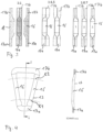
- FIG 3 shows corresponding changes in cross section on the coil disk 6 in a schematic side view figure 3 a winding 13 is shown schematically on the left under the ratio 1:1, in which the passive areas 17a and 17b are only half as thick as the active areas 16. In a single coil disk 6, only the passive areas 17a and 17b always partially overlap ( and never complete either), but never the active areas 16.
- the thicker active areas 16 are in the same plane in the left view of FIG figure 3 arranged one behind the other, while the passive areas 17a and 17b are only half as thick due to the change in cross section and the different levels result in an overall ratio between active areas 16 and passive areas 17a and 17b of 1:1, ie the sum of the thicknesses of the passive areas 17a and 17b just the thickness of the active regions 16 in cross section is equivalent to.
- the coil disk 6 is again shown in cross section.
- the passive areas 17 in the cross-sectional view shown are just 1.5 times thicker than the active areas 16 as a result of the overlap, which require less installation space in a lateral view because of their arrangement one behind the other.
- the two exemplary embodiments shown at 1:1.5 show different plane changes, resulting in a cavity to the right of active region 16 in the first exemplary embodiment (left) and two cavities on both sides of active region 16 in the second exemplary embodiment (right).
- the magnets of the magnet arrangement can be introduced into cavities designed in this way and the axial distance or gap between the active regions 16 and the permanent magnets 5 can thus be reduced (even if this cannot disappear completely). The available installation space is therefore used more efficiently.
- the cavities that form can also be used for cooling.
- a ratio of 1:0.7 is shown.
- the three exemplary embodiments shown show the formation of cavities by corresponding changes in cross section and level in the passive regions 17a and 17b. These cavities can also be used for cooling.
- flexible stranded wires made of copper or aluminum with a diameter of less than 2 mm, namely 1.2 mm in the illustrated exemplary embodiment are preferably used for the windings 13, consisting of several individual wires which are electrically insulated from one another and have a diameter of less than 0.2 mm, but typically 0.05 mm in the illustrated embodiment.
- a hollow space formed between the active regions 16 embodied as webs of the coil disks 6 forming the coil module 18 can be used for a cooling medium to flow through.
- the coil disks 6 are covered with a fluid-tight film made of an electrically non-conductive material on a side facing the magnet disk 4, so that the coil module 18 formed from a plurality of coil disks 6 is sealed off from the outside.
- the cavities can be rectangular, triangular or trapezoidal or in complex shapes.
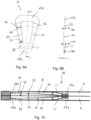
- figure 4 is in the left figure in a plan view one of the windings 13 as shown in FIG figure 2 played back. From the on the right side of figure 4 The sectional view shown through the winding 13 shows that the thickness in the active areas 16 is greater than in the passive areas 17a and 17b.
- the circles K1 and K2 represent as in 2 represents the extent of the active areas 16.
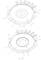
- figure 5 shows in one figure 2 a corresponding top view of a coil module 18, in which two coil disks 6 are arranged one behind the other in the axial direction and are each embedded in a coil carrier ring 20 supplementing the coil carrier 15, with electrical contacts 19 being led out of the coil carrier ring 20 from the windings 13.
- the coil support ring 20 is made of a fiberglass-epoxy resin fabric.
- FIG 6 a sectional view of the coil module 18 is shown, the two coil disks 6 combined with one another being arranged in such a way that a cavity 21 is formed between the active regions 16 of both coil disks 6 and forms the cooling channel described in this document. Since the coil disks are sealed in a fluid-tight manner by means of a foil, a cooling medium can be introduced into this cavity 21 .
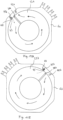
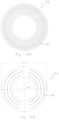
- FIG 7 shows an inner side of a coil disk 6 of a coil module for an electrical machine, on the basis of which the cooling geometry is explained in more detail.
- the coil disk 5 has a coil carrier 15 made of an electrically insulating material and at least one winding 13 made of an electrically conductive material, which is arranged on or in the coil disk 6 encircling a center point 14 of the at least one coil disk 6 .
- the windings 13 are advantageously the windings with active areas 16 and passive areas 17a, 17b described in more detail in this document, the active areas 16 of different windings 13 not overlapping one another, but each passive area 17a, 17b of one of the windings 13 partially covers the corresponding passive areas 17a, 17b of the two immediately adjacent windings 13, and in the active areas 16 the respective winding 13 has a greater thickness in the axial direction in cross-section than in the passive areas 17.
- the at least one winding 13 can, for example, also be in the form of at least one winding which is arranged in a meandering manner around the center point 14 .
- the reel disk 6 also has a substantially annular recess 22 .
- the recess 22 is located on the inner side of the coil disk 6, ie the side that faces the other coil disk in the coil module, so that the recess 22 is enclosed within the two coil disks and thus forms the cooling channel.
- the recess 22 has an outer edge 24 and an inner edge 26 from which the recess 22 is recessed relative to the remaining surface of the reel disc 6 . That is, the inner side of the coil disk 6 apart from the recess 22 substantially in a Level is, so that the edges 24 and 26 each represent the transition from the flat inner side of the coil disc 6 to the recess 22.
- the recess 22 is drawn exactly as a ring in this exemplary embodiment, it does not have to be an exact ring shape according to the invention.
- the recess 22 extends essentially around the center 14 and is not located in the center 14 itself.
- the recess 22 can have a web or a plurality of webs, which are explained in more detail elsewhere in this document, which interrupt the recess 22 .
- the inner edge 26 and/or outer edge 24 of the recess 22 need not be exactly circular and may be polygonal or irregular in shape, for example.
- the inner edge 26 of the recess 22 is located in the area of the transition from the active areas 16 to the inner passive areas 17a of the windings 13.
- the outer edge 24 of the recess 22 is located at the radially outermost area of the outer passive areas 17b of the windings 13.
- This arrangement of the recess 22 can be advantageous since the radially inner passive areas 17a are thicker than the radially outer passive areas 17b due to the limited space and the inner passive areas 17a of immediately adjacent windings 13 overlap in contrast to the active areas 16, so that the total thickness in the axial direction of the radially inner passive areas 17a is greater than the thickness of the active areas 16.
- Space for the recess 22 is therefore available in the area of the active areas 16 and possibly in the area of the outer passive areas 17b.
- the outer edge 24 of the recess 22 can also lie at the transition between the active areas 16 and the radially outer passive areas 17b.
- the recess 22 can be arranged differently, e.g., where space, capability, and/or efficiency are compromised.
- the recess 22 can have different cross sections, as shown in Figures 8A to 8D is shown as an example.
- the Figures 8A to 8D each show a sectional view of the in figure 7 shown level BB.
- the coil disk 6 has a ceramic boundary, which is described in this document and which separates the coil carrier 15 from the cooling channel formed by the recess 22, so that the material of the coil carrier 15 does not absorb the coolant (in particular coolant containing water). .
- Figure 8A shows a recess 22 with a rectangular cross-section.
- the recess 22 has an outer side surface 30, a bottom surface 28 and an inner side surface 32, with the inner and outer side surfaces 30, 32 being respectively orthogonal to the bottom surface 28 and the bottom surface 28 being parallel to the inner side of the reel disc.
- the recess 22 thus has a constant depth 34 along the radial direction from the inside to the outside, i.e. from the inner edge 26 to the outer edge 24.
- Figure 8B shows a recess 22 with a trapezoidal cross-section.
- the side walls 30 and 32 are not orthogonal to the bottom surface 28, but inclined to the bottom surface 28, so that the depth of the recess 22 in the region of the side walls 30, 32 towards the bottom surface 28 steadily increases.
- Figure 8C shows a recess 22 with a depth 34a, 34b increasing in the radial direction from the inside to the outside, ie from the inner edge 26 to the outer edge 24. That is, the bottom surface 28 is at least partially non-parallel to the inner side of the reel disk.
- a portion of the bottom surface 28, such as a radially outer portion of the bottom surface 28 may be parallel to the inner side of the coil disk, while another portion of the bottom surface 28, such as a radially inner portion of the bottom surface 28, may be inclined such that the Depth 34a, 34b of the recess 22 increases from radially inside to radially outside.
- the inner side surface 32 and the outer side surface 30 may each be orthogonal or angled to the inner side of the reel disk. In the present example, the outer side surface 30 is orthogonal to the inner side of the coil disc, whereas the inner side surface 32 is angled thereto.
- the recess 22 can be arranged in the coil disk in such a way that the above-described part of the bottom surface 28 lying parallel to the inner side of the coil disk is in the region of the radially outer passive regions 17b of the windings, including their radially running regions in which a change in cross section occurs.
- the inclined part of the bottom surface 28 lies in the area of the fanned out active areas of the windings.
- the inner side face 32 lies in the area of the inner passive areas of the windings, in which a change in cross section occurs.
- Figure 8D shows a cross-section of a recess 22, in which the transitions from the inner side of the coil disc to the inner side surface 32, to the bottom surface 28 and to the outer Side surface 30 are continuous and / or continuous. Such steady and/or continuous transitions are also possible for the in Figures 8A to 8C shown cross-sections possible.
- the recess 22 can also have a cross-sectional shape resulting from a combination of the Figures 8A to 8D shown cross sections results.
- FIGS 9A and 9B shows a top view of a winding 13, on the basis of which the "fanning out” disclosed in the context of the document is explained in more detail.
- the winding has two radially extending active areas 16 and an inner tangentially extending passive area 17a and an outer tangentially extending passive area 17b, which respectively connect the two active areas 16 to one another.
- the thickness in the axial direction of the winding 13 in the area of the active areas 16 is greater than the thickness in the axial direction of the passive areas 17a, 17b.
- the passive areas 17a, 17b Adjacent to the active areas 16, the passive areas 17a, 17b have short, radial areas 35 and 36, in which there are changes in the cross section of the respective winding 13, which can also be associated with a change in level. Such transition areas can also be located in the active areas 16 .
- the active areas 16 have a fanned out geometry. That is, in the radial direction from the inside to the outside, the width in the tangential direction of the winding 13 in the active areas 16 increases, i.e. the width in the tangential direction of the winding 13 in the active areas 16 has at the radially innermost point, which is at the inner Cross-section change 35 borders, a minimum value 38 and at the radially outermost point, which borders on the outer cross-section change 36, a maximum value 40.
- the width of the winding in the cross-section changes 35, 36 can be within and/or outside of these values.
- the thickness in the axial direction of the winding in the active areas 16 decreases in the radial direction from the inside to the outside, i.e.
- the thickness of the winding can lie within and/or outside of these values.
- the cross-sectional area of the winding 13 in the active regions 16 remains essentially constant along the radial direction.
- This form of winding with the fanned-out active areas 16 can advantageously be combined with the Figure 8C shown recess, ie the "V-Cooling Geometry" can be combined. For example, this is in figure 10 shown.
- FIG 10 shows a sectional view through a coil module 18.
- the coil module has first and second coil disks 6, which each have windings 13, which in Figures 9A and 9B have the fanned out geometry shown.
- the first and second coil disk 6 each have a substantially ring-shaped recess 22, which each extend from the inner cross-sectional changes 35 of the windings 13 to the outer passive areas 17b of the windings. Between the changes in cross section 35 and 36, the depth of the recesses 22 increases continuously from radially inwards to radially outwards, so that the recesses have the so-called “V-Cooling” geometry.
- both the first and the second coil disk 6 have a recess 22 which, when the coil module 18 is in the assembled state, lies exactly opposite one another and thus delimits and forms the cooling channel 23 .
- the Figures 11A and 11B 12 and 12 each show a plan view of the inner side of a first coil disk 6a and a second coil disk 6b, which are intended to be assembled into a coil module. For the sake of clarity, the windings are not shown in these figures.
- the first coil disk 6a and the second coil disk 6b each have a substantially annular recess 22a, 22b. Furthermore, a web 38a is formed in the recess 22a and a web 38b is formed in the recess, the upper side of which lies in the same plane as the remaining inner side of the coil disk 6a, 6b (ie apart from the recess 22a, 22b).
- the first spool disk 6a further has an inlet hole 40a, an inlet channel 44 and an outlet hole 42a.
- the inlet port 44 forms an inlet port 43 in the side surface of the recess 22a.
- the second spool disc 6b has an inlet hole 40b, an outlet hole 42b, and an outlet port 46 forming an outlet port 45 in the side surface of the recess 22b.
- the coolant in the assembled state of the coil module, can flow through the inlet hole 40a, b, the inlet channel 44, the inlet opening 43 into the coolant channel formed by the recesses 22a, 22b and then through the outlet opening 45 into the outlet channel 46 and the outlet hole 42a, b flow, as visualized by means of arrows.
- the electrical machine typically has a number of such coil modules, which are connected to one another via coil spacers.
- the coil spacers have corresponding inlet and outlet holes so that when assembled all Inlet holes line up and all outlet holes line up.
- the inlet and outlet holes can be omitted in the coil module or in the spacer, which is located at an axial end of the electrical machine.
- the coolant can be supplied and removed through the inlet and outlet holes in the coil module or spacer, which lies at the opposite axial end of the electric machine.
- FIGS. 12A, 12B and 12C show a coil module, on the basis of which the "fanning out” of the active areas disclosed herein and the "V-Cooling" are explained.
- the coil module comprises a first coil disk 6a and a second coil disk 6b.
- the first coil disk 6a and the second coil disk 6b are attached to each other such that inner sides thereof face each other.
- the two recesses 22a, 22b provided on the inner side thus point towards one another or lie on top of one another, so that they form a cooling channel 23 between the coil disks 6a, 6b.
- the first coil disk 6a and the second coil disk 6b each comprise a plurality of windings 13. These windings 13 of each coil disk 6a, 6b can be configured differently.
- a first group of windings 13a lies in a first plane, so that both the active areas 16a and the passive areas lie in the first plane.
- a second group of windings 13b is arranged such that the tangential areas lie in a second plane offset from the first plane and the active areas 16b lie in the first plane. The level change takes place at the transitions to the active areas 16b.
- a third group of windings 13c is arranged in such a way that the tangential areas lie both in the first plane and in the second plane, so that there is a plane change in the tangential areas.
- Figure 12B shows a plan view of the coil module 18.
- the windings have active areas 16 and passive areas 17a, 17b as disclosed herein. It can be clearly seen that the active areas 16 of the windings 13 have the fanned out shape described herein.
- windings 13a, 13b and 13c located. It is clearly visible that their adjacent active regions 16a, 16b, 16 essentially adjoin one another, so that there is preferably no gap.
- Figure 12C shows a perspective view of the coil module 18 with some of the windings omitted so that the channel 23 between the first coil disc 6a and the second coil disc 6b is clearly visible. This means that a space is formed between the windings 13d of the first coil disk 6a and the windings 13e of the second coil disk, which space increases in its axial height (or thickness in the axial direction) from radially inside to radially outside.
- the coil module has a first coil disk 6a and a second coil disk 6b.
- the first coil disk 6a has a first coil carrier 15a and a first coil carrier ring 20a, which surrounds the first coil carrier 15a radially on the outside.
- the second coil disk 6b has a second coil carrier 15b and a second coil carrier ring 20b, which surrounds the second coil carrier radially on the outside.
- windings 13 are embedded in the first and second coil carriers 15a, 15b.
- the windings 13 have essentially radially running active regions 16 and essentially tangentially running inner passive regions 17a and outer passive regions 17b.
- the windings 13 are electrically connected to contacts 19 .
- Figure 13B shows a plan view of the in 13A coil carrier shown.
- Figure 13C shows a cross-section along the in Figure 13B shown cutting plane AA.
- the first and second coil disks 6a and 6b are formed such that a substantially annular cooling passage 23 is formed between them.
- the cooling channel 23 extends in a radial area of the coil disks 6a and 6b and coil carriers 15a and 15b, in which the active areas 16 and the outer passive areas 17b of the windings 13 are arranged.
- the coil module 18 also has first and second ceramic boundaries 56a and 56b, a radially inner ceramic boundary 57 and a radially outer ceramic boundary 58 which surround the cooling channel 23 and delimit it from the first coil carrier 15a and second coil carrier 15b.
- Figure 13D shows a cross-section along the in Figure 13B shown cutting plane BB.
- the inlet opening 54 and the outlet opening 55 are shown.
- the first and second ceramic barriers 56a and 56b have an opening 62 and 61, respectively, which corresponds to the inlet opening 54 and the outlet opening 55, respectively.
- coolant can enter the cooling channel 23 through the inlet opening 54 , flow through it and exit again through the outlet opening 55 .
- the seals 56a, 56b, 57 and 58 ensure that the coolant does not come into contact with the material of the coil carriers 15a and 15b.
- FIG 14A shows a coil disk 6, as is the case, for example, in Figures 13A-C shown coil module 18 is installed.
- the coil disk 6 has a coil carrier 15 which contains the windings disclosed in this document, and a coil carrier ring 20 .
- the coil carrier 15 has a radially inner area 50 and a radially outer area 51 , the radially inner area 50 being higher than the radially outer area 51 .
- the radially inner area 50 has a greater axial thickness than the radially outer area 51.
- the radially inner passive areas of the windings are arranged in the radially inner area 50.
- the active areas and the radially outer areas of the windings are arranged in the radially outer area 51 .
- the coil carrier ring 20 is in turn raised in relation to the radially outer region 51 of the coil carrier 15, so that it is essentially at the same height as the radially inner region 50 of the coil carrier 15.
- the coil carrier ring 20 also has an inlet opening 54 and an outlet opening 55 .
- the coil carrier ring 20 Around the inlet opening 54 the coil carrier ring 20 has a recessed area 52 which is essentially at the same level as the radially outer area 51 of the coil carrier 15 and merges into it.
- the coil carrier ring 20 Around the outlet opening 55, the coil carrier ring 20 has a recessed area 53 which is essentially at the same level as the radially outer area 51 of the coil carrier 15 and merges into it.
- Figure 14B shows the in Figure 14A bobbin disc 6 shown with a ceramic border 56.
- the ceramic border 56 is essentially in the form of an annular disc which is arranged in the radially outer region 51 and in the recessed regions 52 and 53 of the bobbin ring.
- the substantially ring-shaped ceramic disk 56 has two projections 59 and 60 which correspond to the recessed areas 52 and 53 of the bobbin ring 20 .
- the coil disc 6 is shown as having a radially inner boundary 57 surrounding the radially inner edge of the annular ceramic disc 56 .
- the coil disk 6 further includes a radially outer boundary 58 surrounding the radially outer edge of the annular ceramic disk 56 .
- the annular ceramic disk 56 also has two openings 61 and 62 corresponding to the inlet opening 54 and the outlet opening 55 .
- the cooling channel is completely delimited from the surrounding material of the coil carrier 15 and the coil carrier ring 20 .
- the coil disk 6 is a first coil disk and the ceramic boundary 56 is a first coil disk.
- the coil module disclosed in this document also has a second coil disk, which essentially corresponds to a coil disk that is mirrored to the coil disk 6, and a second ceramic boundary.
- Figure 15A 12 shows a first or second ceramic demarcation 56.
- the ceramic demarcation 56 has a plurality of fasteners 53 oriented perpendicular to the ceramic demarcation 56 in the form of .
- the connecting elements 53 connect the first and second ceramic borders.
- FIG. 12 shows a first or second ceramic boundary 56 with connecting elements 64 in the form of conductive structures or conductive ribs. These connecting elements 64 connect the first and second ceramic boundaries in the coil module to two ceramic boundaries 56.
- the ceramic border 56 has a plurality of projections 65 which are in the shape of "pie slices" or sectors of a circle.
- the projections 65 are adapted to protrude into corresponding gaps formed in the bobbin between two adjacent active areas of the windings.
- 17 shows a vehicle 150 with an electric machine 152 disclosed in this document.
- FIG. 18 shows a machine tool 154 with an electrical machine 156 disclosed in this document.
Landscapes
- Engineering & Computer Science (AREA)
- Power Engineering (AREA)
- Windings For Motors And Generators (AREA)
- Motor Or Generator Cooling System (AREA)
Claims (14)
- Module de bobine (18) pour une machine électrique, présentant :un premier disque de bobine (6, 6a) avec un premier support de bobine (15, 15a) en un matériau électriquement isolant et au moins un enroulement (13) en un matériau électriquement conducteur incorporé dans le premier support de bobine (15, 15a) ;un deuxième disque de bobine (6, 6b) avec un deuxième support de bobine (15, 15b) en un matériau électriquement isolant et au moins un enroulement (13) en un matériau électriquement conducteur incorporé dans le deuxième support de bobine (15, 15b) ;les disques de bobine (6, 6a, 6b) étant agencés l'un derrière l'autre dans une direction axiale de la machine électrique ;le premier disque de bobine (6, 6a) et le deuxième disque de bobine (6b) étant configurés et montés l'un sur l'autre de telle sorte qu'un canal de refroidissement (23) essentiellement annulaire pour un agent de refroidissement est formé dans la direction axiale entre le premier disque de bobine (6, 6a) et le deuxième disque de bobine (6b) ;caractérisé en ce quele premier disque de bobine (6, 6a) présente une première délimitation céramique (56, 56a) ;le deuxième disque de bobine (6, 6b) présente une deuxième délimitation céramique (56, 56b) ;la première délimitation céramique (56, 56a) et la deuxième délimitation céramique (56, 56b) forment chacune au moins partiellement une paroi intérieure du canal de refroidissement (23) essentiellement annulaire ;le premier support de bobine (15, 15a) et/ou le deuxième support de bobine (15, 15b) présente(nt), sur un côté tourné vers le deuxième (6b) et respectivement le premier disque de bobine (6, 6a) dans la direction axiale, un évidement (22) essentiellement annulaire, de telle sorte que l'évidement (22) est enfermé à l'intérieur des deux disques de bobine (6, 6a, 6b) et forme ainsi le canal de refroidissement (23) ; etla première délimitation céramique (56, 56a) et/ou la deuxième délimitation céramique (56, 56b) est/sont fournie(s) sous la forme d'un disque céramique essentiellement annulaire qui est agencé dans l'évidement essentiellement annulaire (22) sur le premier support de bobine et respectivement le deuxième support de bobine.
- Module de bobine (18) selon la revendication 1, la première et/ou la deuxième délimitation céramique (56, 56a, 56b) présentant une céramique à base d'aluminium et/ou à base de silicium, de préférence un matériau du groupe constitué par l'oxyde d'aluminium, le nitrure d'aluminium, le carbure de silicium et le nitrure de silicium.
- Module de bobine (18) selon l'une quelconque des revendications précédentes, la première délimitation céramique (56, 56a) formant, dans toute la zone radiale du canal de refroidissement essentiellement annulaire, la paroi intérieure du canal de refroidissement essentiellement annulaire (23) ; et/ ou
la deuxième délimitation céramique (56, 56b) formant, dans toute la zone radiale du canal de refroidissement essentiellement annulaire, la paroi intérieure du canal de refroidissement essentiellement annulaire (23). - Module de bobine (18) selon l'une quelconque des revendications précédentes, la première délimitation céramique (56, 56a) présentant un premier disque céramique agencé sur le premier support de bobine (15, 15a) et la deuxième délimitation céramique (56, 56b) présentant un deuxième disque céramique agencé sur le deuxième support de bobine (15, 15b) ;
le premier disque céramique (56, 56a) et/ou le deuxième disque céramique (56, 56b) présentant de préférence une épaisseur comprise entre 0,1 mm et 1 mm, de préférence entre 0,2 mm et 0,8 mm, de manière davantage préférée entre 0,35 mm et 0,7 mm. - Module de bobine (18) selon l'une quelconque des revendications 1 à 3, l'une des délimitations céramiques (56, 56a ; 56b) étant fournie sous la forme du disque céramique et l'autre délimitation céramique (56b ; 56, 56a) présentant un revêtement céramique appliqué sur le premier support de bobine (15, 15a) ;
le premier revêtement céramique et/ou le deuxième revêtement céramique présentant de préférence une épaisseur comprise entre 1 µm et 100 µm, de préférence entre 1 µm et 50 µm, de manière davantage préférée entre 1 µm et 30 µm. - Module de bobine (18) selon l'une quelconque des revendications précédentes, présentant en outre :au moins un élément de liaison (63, 64), qui est agencé dans le canal de refroidissement essentiellement annulaire (23) et est relié, de préférence est configuré d'un seul tenant, à la fois avec la première délimitation céramique (56, 56a) et la deuxième délimitation céramique (56, 56b) ;l'au moins un élément de liaison (63, 64) de préférence- présentant une céramique à base d'aluminium et/ou à base de silicium, de préférence un matériau du groupe constitué par l'oxyde d'aluminium, le nitrure d'aluminium, le carbure de silicium et le nitrure de silicium ; et/ou- l'au moins un élément de liaison (63, 64) étant de préférence collé ou configuré d'un seul tenant avec la première délimitation céramique et/ou la deuxième délimitation céramique ; et/ou- présentant une entretoise agencée de préférence perpendiculairement au premier et/ou au deuxième disque de bobine (6, 6a, 6b) ; et/ou- présentant une nervure s'étendant parallèlement au premier et/ou au deuxième disque de bobine (6, 6a, 6b).
- Module de bobine (18) selon l'une quelconque des revendications précédentes, présentant en outre une délimitation céramique radialement intérieure (57) et une délimitation céramique radialement extérieure ;la délimitation céramique radialement intérieure (57) étant de préférence configurée sous forme de collerette et/ou de collier et étant agencée, vue dans la direction radiale, à l'intérieur de manière adjacente à la première délimitation céramique (56, 56a) et à la deuxième délimitation céramique (56, 56b) ; etla délimitation céramique radialement extérieure (58) étant de préférence configurée sous forme de collerette et/ou de collier et étant agencée, vue dans la direction radiale, à l'extérieur de manière adjacente à la première délimitation céramique (56, 56a) et à la deuxième délimitation céramique (56, 56b).
- Module de bobine (18) selon l'une quelconque des revendications précédentes, le premier disque de bobine (6, 6a) et/ou le deuxième disque de bobine (6, 6b) présentant une ouverture d'entrée (43, 54) pour diriger un agent de refroidissement dans le canal de refroidissement essentiellement annulaire (23) ; et/ou
le premier disque de bobine (6, 6a) et/ou le deuxième disque de bobine (6, 6b) présentant une ouverture de sortie (45, 55) pour diriger un agent de refroidissement vers l'extérieur à partir du canal de refroidissement essentiellement annulaire (23). - Module de bobine (18) selon l'une quelconque des revendications précédentes, une pluralité d'enroulements individuels (13) en un matériau électriquement conducteur étant incorporés dans le premier support de bobine (15, 15a), lesquels sont chacun incorporés dans le premier support de bobine (15, 15a) circonférentiellement autour d'un centre (14) du premier support de bobine (15, 15a),une pluralité d'enroulements individuels (13) en un matériau électriquement conducteur étant incorporés dans le deuxième support de bobine (15, 15b), lesquels sont chacun incorporés dans le deuxième support de bobine (15, 15b) circonférentiellement autour d'un centre (14) du deuxième support de bobine (15, 15b),chacun des enroulements (13) présentant deux zones actives (16) s'étendant radialement à partir du centre (14) et deux zones passives (17b) s'étendant tangentiellement sur son bord radialement extérieur et intérieur et,en vue de dessus sur le disque de bobine (6, 6a, 6b), les zones actives (16) de différents enroulements (13) ne se recouvrant pas, mais chaque zone passive (17a, 17b) de l'un des enroulements (13) recouvrant partiellement les zones passives (17a, 17b) correspondantes des deux enroulements (13) directement voisins, l'enroulement (13) respectif présentant dans les zones actives (16), en coupe transversale, une épaisseur plus grande dans la direction axiale que dans les zones passives (17a, 17b).
- Module de bobine (18) selon la revendication 9, des zones actives voisines (16) de la pluralité d'enroulements individuels (13) du premier disque de bobine (6, 6a) et du deuxième disque de bobine (6, 6b) étant espacées les unes des autres dans la direction tangentielle, de telle sorte qu'un espace est agencé entre les zones actives voisines (16), et
la première délimitation céramique (56, 56a) et la deuxième délimitation céramique (56, 56b) présentant chacune des saillies (65) qui pénètrent dans les espaces agencés entre les zones actives voisines (16). - Module de bobine (18) selon la revendication 9 ou 10, le canal de refroidissement (23) étant agencé au moins dans la zone des zones actives (16) s'étendant radialement et de préférence également dans la zone des zones passives (17b) radialement extérieures.
- Module de bobine (18) selon l'une quelconque des revendications 9 à 11, les enroulements étant formés d'un toron fin de plusieurs fils isolés électriquement les uns des autres, qui présentent un diamètre de fil inférieur ou égal à 0,1 mm.
- Machine électrique avec un palier (1, 3) et un arbre (2) guidé dans le palier (1, 3), au moins un module magnétique (4) avec plusieurs aimants permanents (5) et au moins un module de bobine (18) selon l'une quelconque des revendications précédentes étant agencés de manière concentrique le long de l'arbre (2).
- Véhicule (150) ou machine-outil (154) avec une machine électrique selon la revendication 13.
Priority Applications (12)
| Application Number | Priority Date | Filing Date | Title |
|---|---|---|---|
| HRP20230967TT HRP20230967T1 (hr) | 2021-04-27 | 2021-04-27 | Zavojnični modul za električni stroj |
| ES21170784T ES2953788T3 (es) | 2021-04-27 | 2021-04-27 | Módulo de bobina para una máquina eléctrica |
| EP21170784.9A EP4084288B1 (fr) | 2021-04-27 | 2021-04-27 | Module de bobine pour une machine électrique |
| PL21170784.9T PL4084288T3 (pl) | 2021-04-27 | 2021-04-27 | Moduł cewki dla maszyny elektrycznej |
| HUE21170784A HUE063126T2 (hu) | 2021-04-27 | 2021-04-27 | Tekercsmodul villamos géphez |
| MX2023012817A MX2023012817A (es) | 2021-04-27 | 2022-04-27 | Modulo de bobina para maquina electrica. |
| PCT/EP2022/061234 WO2022229272A1 (fr) | 2021-04-27 | 2022-04-27 | Module de bobine pour une machine électrique |
| JP2023566535A JP2024516832A (ja) | 2021-04-27 | 2022-04-27 | 電気機械用のコイルモジュール |
| AU2022264829A AU2022264829A1 (en) | 2021-04-27 | 2022-04-27 | Coil module for an electric machine |
| CN202280045828.1A CN117581450A (zh) | 2021-04-27 | 2022-04-27 | 用于电机的线圈模块 |
| US18/557,679 US20240322616A1 (en) | 2021-04-27 | 2022-04-27 | Coil module for electric machine |
| KR1020237040705A KR20240026902A (ko) | 2021-04-27 | 2022-04-27 | 전기 기계의 코일 모듈 |
Applications Claiming Priority (1)
| Application Number | Priority Date | Filing Date | Title |
|---|---|---|---|
| EP21170784.9A EP4084288B1 (fr) | 2021-04-27 | 2021-04-27 | Module de bobine pour une machine électrique |
Publications (2)
| Publication Number | Publication Date |
|---|---|
| EP4084288A1 EP4084288A1 (fr) | 2022-11-02 |
| EP4084288B1 true EP4084288B1 (fr) | 2023-06-07 |
Family
ID=75728623
Family Applications (1)
| Application Number | Title | Priority Date | Filing Date |
|---|---|---|---|
| EP21170784.9A Active EP4084288B1 (fr) | 2021-04-27 | 2021-04-27 | Module de bobine pour une machine électrique |
Country Status (12)
| Country | Link |
|---|---|
| US (1) | US20240322616A1 (fr) |
| EP (1) | EP4084288B1 (fr) |
| JP (1) | JP2024516832A (fr) |
| KR (1) | KR20240026902A (fr) |
| CN (1) | CN117581450A (fr) |
| AU (1) | AU2022264829A1 (fr) |
| ES (1) | ES2953788T3 (fr) |
| HR (1) | HRP20230967T1 (fr) |
| HU (1) | HUE063126T2 (fr) |
| MX (1) | MX2023012817A (fr) |
| PL (1) | PL4084288T3 (fr) |
| WO (1) | WO2022229272A1 (fr) |
Families Citing this family (1)
| Publication number | Priority date | Publication date | Assignee | Title |
|---|---|---|---|---|
| TWI852894B (zh) * | 2024-03-21 | 2024-08-11 | 吳翔安 | 馬達、發電機或電磁輸送帶之定子或轉子之繞組結構 |
Family Cites Families (72)
| Publication number | Priority date | Publication date | Assignee | Title |
|---|---|---|---|---|
| US405858A (en) * | 1889-06-25 | Nikola Tesla | Magnetic Motor | |
| FR77407E (fr) * | 1960-03-17 | 1962-03-02 | Electronique & Automatisme Sa | Machines électriques tournantes perfectionnées |
| FR79354E (fr) * | 1960-09-08 | 1962-11-23 | Electronique & Automatisme Sa | Machines électriques tournantes perfectionnées |
| US2970238A (en) * | 1959-02-12 | 1961-01-31 | Printed Motors Inc | Printed circuit armature |
| FR78826E (fr) * | 1960-09-08 | 1962-09-14 | Electronique & Automatisme Sa | Machines électriques tournantes perfectionnées |
| US3450919A (en) * | 1965-09-16 | 1969-06-17 | Electronique & Automatisme Sa | Multiple member windings for electrical rotating machines |
| DE2409681A1 (de) * | 1974-02-28 | 1975-09-11 | Retobobina Handelsanstalt | Elektrische ankerwicklung |
| US4187453A (en) * | 1975-01-06 | 1980-02-05 | Jim Zegeer | Electric motor drive system |
| US4115915A (en) * | 1975-07-31 | 1978-09-26 | General Electric Company | Process for manufacturing motor having windings constructed for automated assembly |
| JPS5678342A (en) * | 1979-11-26 | 1981-06-27 | Kangiyou Denki Kiki Kk | Printed circuit |
| US4645961A (en) * | 1983-04-05 | 1987-02-24 | The Charles Stark Draper Laboratory, Inc. | Dynamoelectric machine having a large magnetic gap and flexible printed circuit phase winding |
| DE3526166C2 (de) * | 1984-07-23 | 1996-05-02 | Asahi Chemical Ind | Bürstenloser Elektromotor und Verfahren zum Herstellen einer Spuleneinheit für diesen |
| CH660542A5 (fr) * | 1984-08-31 | 1987-04-30 | Asgalium Sa | Moteur electrique. |
| JPS6244056A (ja) * | 1985-08-20 | 1987-02-26 | Kiyonori Fujisaki | 直流モ−タ |
| US4933584A (en) * | 1988-12-22 | 1990-06-12 | General Electric Company | Electronically commutated motor having skewed magnetics |
| US6033764A (en) * | 1994-12-16 | 2000-03-07 | Zecal Corp. | Bumped substrate assembly |
| US5789841A (en) * | 1995-06-07 | 1998-08-04 | Kollmorgen Corporation | Axial air gap brushless motor with layered disk stator |
| CA2262732C (fr) * | 1996-08-09 | 2006-05-23 | The Turbo Genset Company Limited | Machine electrique rotative |
| DE19958682A1 (de) * | 1999-12-06 | 2001-06-28 | Siemens Ag | Permanenterregter Synchronmotor |
| CN1520632A (zh) * | 2001-06-26 | 2004-08-11 | �Ƚ�ת��ϵͳ���Ϲ�˾ | 无刷直流电动机 |
| WO2004015843A1 (fr) * | 2002-08-07 | 2004-02-19 | Hitachi Metals, Ltd. | Bobine laminee et moteur sans balai l'utilisant |
| PT1590871E (pt) * | 2003-02-07 | 2008-08-27 | Core Motion Inc | Dispositivo energético rotativo de campo axial de condutor optimizado |
| US7156611B2 (en) * | 2003-03-13 | 2007-01-02 | Sanyo Denki Co., Ltd. | Counterrotating axial blower |
| US6998751B2 (en) * | 2003-09-16 | 2006-02-14 | Rotys Inc. | High reliability electric drive |
| US7607220B2 (en) * | 2004-03-22 | 2009-10-27 | Gm Global Technology Operations, Inc. | Method for establishing electrical connections in a hybrid electro-mechanical transmission |
| US7081696B2 (en) * | 2004-08-12 | 2006-07-25 | Exro Technologies Inc. | Polyphasic multi-coil generator |
| US7514833B2 (en) * | 2004-09-03 | 2009-04-07 | Ut-Battelle Llc | Axial gap permanent-magnet machine with reluctance poles and PM element covers |
| US20060055265A1 (en) * | 2004-09-16 | 2006-03-16 | Zalusky James T | Printed circuit board motor |
| US7180216B2 (en) * | 2004-12-18 | 2007-02-20 | Light Engineering, Inc. | High-intensity discharge lighting system and alternator power supply |
| US8058762B2 (en) * | 2005-01-19 | 2011-11-15 | Daikin Industries, Ltd. | Rotor, axial gap type motor, method of driving motor, and compressor |
| US20070296369A1 (en) * | 2005-09-16 | 2007-12-27 | Showway Yeh | Thin linear, rotary, and step motor and electromagnet driver using printed coil board |
| JP4844877B2 (ja) * | 2006-05-29 | 2011-12-28 | 日本電産株式会社 | 直列式軸流ファンおよび軸流ファン |
| CN102647058A (zh) * | 2006-06-08 | 2012-08-22 | Exro技术公司 | 电力设备 |
| JP4434181B2 (ja) * | 2006-07-21 | 2010-03-17 | 株式会社日立製作所 | 電力変換装置 |
| JP4699961B2 (ja) * | 2006-08-30 | 2011-06-15 | 本田技研工業株式会社 | 回転電機用コイルとその製造方法、並びに回転電機とその製造方法 |
| GB0617989D0 (en) * | 2006-09-13 | 2006-10-18 | Denne Phillip R M | Improvements in electrical machines |
| US8558425B2 (en) * | 2006-10-26 | 2013-10-15 | Deere & Company | Motor having stator with generally planar windings |
| US20080100166A1 (en) * | 2006-10-26 | 2008-05-01 | Deere & Company | Motor having stator with generally planar windings |
| EP2327137B1 (fr) * | 2008-08-15 | 2020-01-22 | Millennial Research Corporation | Moteur régénérateur et bobine |
| US10038349B2 (en) * | 2008-08-15 | 2018-07-31 | Millennial Research Corporation | Multi-phase modular coil element for electric motor and generator |
| CN101741153B (zh) * | 2008-11-10 | 2013-07-31 | 株式会社日立产机系统 | 电枢铁心、使用了该电枢铁心的电动机、轴向间隙型旋转电动机、及其制造方法 |
| JP2010138895A (ja) * | 2008-11-11 | 2010-06-24 | Nippon Densan Corp | 直列式軸流ファン |
| CN102292897B (zh) * | 2009-01-16 | 2014-04-02 | 科尔风力发电公司 | 用于轴向场装置的扇块式定子 |
| TWI388109B (zh) * | 2009-08-14 | 2013-03-01 | Metal Ind Res & Dev Ct | A stator structure and a micro motor having the stator structure and a method of manufacturing the same |
| JP4699570B1 (ja) * | 2009-12-22 | 2011-06-15 | 株式会社コスモメカニクス | ディスク型コイル |
| US8319595B2 (en) * | 2010-01-13 | 2012-11-27 | Cosmo Mechanics Co., Ltd. | Coil apparatus |
| JP5653072B2 (ja) * | 2010-05-19 | 2015-01-14 | 本田技研工業株式会社 | ステータコイルアッセンブリ |
| JP5534338B2 (ja) * | 2010-09-30 | 2014-06-25 | 日立工機株式会社 | ディスクモータ及び電動作業機 |
| JP5534337B2 (ja) * | 2010-09-30 | 2014-06-25 | 日立工機株式会社 | ディスクモータ及び電動作業機 |
| GB2485185A (en) * | 2010-11-04 | 2012-05-09 | Pipera Technologies Ltd | Axial gap electrical machine having integrated stator |
| JP2012152028A (ja) * | 2011-01-19 | 2012-08-09 | Denso Corp | 回転電機 |
| JP6003015B2 (ja) * | 2011-06-24 | 2016-10-05 | ソニー株式会社 | リチウムイオン二次電池、リチウムイオン二次電池用負極、電池パック、電動車両、電力貯蔵システム、電動工具および電子機器 |
| TWI440281B (zh) * | 2011-08-31 | 2014-06-01 | 建準電機工業股份有限公司 | 馬達定子 |
| WO2013032405A1 (fr) * | 2011-09-01 | 2013-03-07 | Agency For Science, Technology And Research | Dispositif de stockage de données |
| JP5880817B2 (ja) * | 2011-09-28 | 2016-03-09 | 日立工機株式会社 | ディスクモータ及びそれを備えた電動作業機 |
| CN103959611B (zh) * | 2011-11-22 | 2015-12-09 | 本田技研工业株式会社 | 电动机的连接机构 |
| WO2013122542A1 (fr) * | 2012-02-13 | 2013-08-22 | Agency For Science, Technology And Research | Moteur et procédé d'assemblage de celui-ci |
| US8736133B1 (en) * | 2013-03-14 | 2014-05-27 | Boulder Wind Power, Inc. | Methods and apparatus for overlapping windings |
| GB201322478D0 (en) * | 2013-12-18 | 2014-02-05 | Gyo Gym Ltd | Improvements in or relating to generating your own power |
| CN104734389A (zh) * | 2013-12-20 | 2015-06-24 | 湖北海山科技有限公司上海分公司 | 定子盘及轴向磁通永磁动能装置 |
| JP6392252B2 (ja) * | 2014-01-21 | 2018-09-19 | 株式会社羽野製作所 | 発電装置および発電装置用電機子構造並びに電機子の製造方法 |
| JP2015228780A (ja) * | 2014-06-03 | 2015-12-17 | 株式会社日立製作所 | アキシャルギャップ型回転電機 |
| US10256758B2 (en) * | 2014-11-26 | 2019-04-09 | Kohler Co. | Printed circuit board based exciter |
| TWI551008B (zh) * | 2015-01-27 | 2016-09-21 | 建準電機工業股份有限公司 | 馬達繞組 |
| CN204559345U (zh) * | 2015-03-31 | 2015-08-12 | 无锡新大力电机有限公司 | 采用印制电路绕组的单定子双转子盘式永磁轮毂电机 |
| US9800109B2 (en) * | 2015-10-02 | 2017-10-24 | E-Circuit Motors, Inc. | Structures and methods for controlling losses in printed circuit boards |
| US9859763B2 (en) * | 2015-10-02 | 2018-01-02 | E-Circuit Motors, Inc. | Structures and methods for controlling losses in printed circuit boards |
| US11342813B2 (en) * | 2016-04-30 | 2022-05-24 | Blue Canyon Technologies Inc. | Printed circuit board axial flux motor with thermal element |
| DE102017204072A1 (de) * | 2017-03-13 | 2018-09-13 | Green Fox e-solutions GmbH | Elektrische Maschine |
| JP7056070B2 (ja) * | 2017-10-13 | 2022-04-19 | 株式会社アイシン | 回転電機 |
| WO2019190959A1 (fr) * | 2018-03-26 | 2019-10-03 | Infinitum Electric Inc. | Système et appareil pour dispositif d'énergie rotatif à champ axial |
| US11283319B2 (en) * | 2019-11-11 | 2022-03-22 | Infinitum Electric, Inc. | Axial field rotary energy device with PCB stator having interleaved PCBS |
-
2021
- 2021-04-27 ES ES21170784T patent/ES2953788T3/es active Active
- 2021-04-27 HR HRP20230967TT patent/HRP20230967T1/hr unknown
- 2021-04-27 HU HUE21170784A patent/HUE063126T2/hu unknown
- 2021-04-27 PL PL21170784.9T patent/PL4084288T3/pl unknown
- 2021-04-27 EP EP21170784.9A patent/EP4084288B1/fr active Active
-
2022
- 2022-04-27 KR KR1020237040705A patent/KR20240026902A/ko active Pending
- 2022-04-27 US US18/557,679 patent/US20240322616A1/en active Pending
- 2022-04-27 AU AU2022264829A patent/AU2022264829A1/en active Pending
- 2022-04-27 WO PCT/EP2022/061234 patent/WO2022229272A1/fr not_active Ceased
- 2022-04-27 CN CN202280045828.1A patent/CN117581450A/zh active Pending
- 2022-04-27 MX MX2023012817A patent/MX2023012817A/es unknown
- 2022-04-27 JP JP2023566535A patent/JP2024516832A/ja active Pending
Also Published As
| Publication number | Publication date |
|---|---|
| US20240322616A1 (en) | 2024-09-26 |
| WO2022229272A1 (fr) | 2022-11-03 |
| MX2023012817A (es) | 2024-01-25 |
| CN117581450A (zh) | 2024-02-20 |
| HRP20230967T1 (hr) | 2023-12-08 |
| JP2024516832A (ja) | 2024-04-17 |
| EP4084288A1 (fr) | 2022-11-02 |
| KR20240026902A (ko) | 2024-02-29 |
| AU2022264829A1 (en) | 2023-11-09 |
| ES2953788T3 (es) | 2023-11-16 |
| HUE063126T2 (hu) | 2024-01-28 |
| PL4084288T3 (pl) | 2023-11-06 |
Similar Documents
| Publication | Publication Date | Title |
|---|---|---|
| EP4035253B1 (fr) | Machine à flux axial | |
| DE3904516C1 (fr) | ||
| EP2368308B1 (fr) | Machine électrique à courant de refroidissement axial et déplacé radialement, et procédé correspondant | |
| DE102008064495B3 (de) | Elektrische Maschine mit mehreren Kühlströmen und Kühlverfahren | |
| WO2021003510A2 (fr) | Stator pour une machine à flux axial | |
| EP4449586A1 (fr) | Rotor pour une machine électrique comprenant un canal de refroidissement dans un séparateur de pôles | |
| EP0952657A2 (fr) | Machine à flux transversal | |
| EP4320709A1 (fr) | Stator de machine électrique à flux axial et machine à flux axial | |
| DE112016003840T5 (de) | Magnetgetriebevorrichtung und Polstück für eine solche Vorrichtung | |
| EP4335020A1 (fr) | Refroidissement de tête d'enroulement | |
| DE102014205034A1 (de) | Statoreinheit für eine elektrische Maschine sowie elektrische Maschine | |
| EP4320708A1 (fr) | Stator de machine électrique à flux axial et machine à flux axial | |
| EP3813237B1 (fr) | Module de bobine pour une machine électrique | |
| EP4084288B1 (fr) | Module de bobine pour une machine électrique | |
| EP1368883A1 (fr) | Sous-ensemble pour une machine electrique et machine electrique comportant un tel sous-ensemble | |
| EP1711994A1 (fr) | Unite modulaire stator | |
| DE102020132094A1 (de) | Elektroblechlamellen mit integrierten Kühlkanälen sowie statischen Strömungswiderständen in einem Stator, einer elektrischen Maschine und einem Kraftfahrzeug | |
| DE19800667C2 (de) | Transversalflußmaschine mit massearmem passiven Rotor | |
| DE19753261A1 (de) | Verfahren zur Kühlung einer Wechselstrommaschine, insbesondere Transversalflußmaschine und Wechselstrommaschine, insbesondere Transversalflußmaschine | |
| WO1994002984A1 (fr) | Machine electrique | |
| DE10020705A1 (de) | Elektrische Maschine | |
| DE102014001023B4 (de) | Elektrische Maschine | |
| WO2011026600A2 (fr) | Machine électrique et procédé de fabrication de ladite machine | |
| DE102023121670A1 (de) | Wicklung und elektrische Rotationsmaschine | |
| DE102024205359A1 (de) | Elektromaschine mit direkter Statorkühlung |
Legal Events
| Date | Code | Title | Description |
|---|---|---|---|
| REG | Reference to a national code |
Ref country code: HR Ref legal event code: TUEP Ref document number: P20230967T Country of ref document: HR |
|
| PUAI | Public reference made under article 153(3) epc to a published international application that has entered the european phase |
Free format text: ORIGINAL CODE: 0009012 |
|
| STAA | Information on the status of an ep patent application or granted ep patent |
Free format text: STATUS: REQUEST FOR EXAMINATION WAS MADE |
|
| 17P | Request for examination filed |
Effective date: 20220216 |
|
| AK | Designated contracting states |
Kind code of ref document: A1 Designated state(s): AL AT BE BG CH CY CZ DE DK EE ES FI FR GB GR HR HU IE IS IT LI LT LU LV MC MK MT NL NO PL PT RO RS SE SI SK SM TR |
|
| GRAP | Despatch of communication of intention to grant a patent |
Free format text: ORIGINAL CODE: EPIDOSNIGR1 |
|
| STAA | Information on the status of an ep patent application or granted ep patent |
Free format text: STATUS: GRANT OF PATENT IS INTENDED |
|
| INTG | Intention to grant announced |
Effective date: 20221222 |
|
| GRAS | Grant fee paid |
Free format text: ORIGINAL CODE: EPIDOSNIGR3 |
|
| GRAA | (expected) grant |
Free format text: ORIGINAL CODE: 0009210 |
|
| STAA | Information on the status of an ep patent application or granted ep patent |
Free format text: STATUS: THE PATENT HAS BEEN GRANTED |
|
| AK | Designated contracting states |
Kind code of ref document: B1 Designated state(s): AL AT BE BG CH CY CZ DE DK EE ES FI FR GB GR HR HU IE IS IT LI LT LU LV MC MK MT NL NO PL PT RO RS SE SI SK SM TR |
|
| REG | Reference to a national code |
Ref country code: GB Ref legal event code: FG4D Free format text: NOT ENGLISH |
|
| P01 | Opt-out of the competence of the unified patent court (upc) registered |
Effective date: 20230425 |
|
| REG | Reference to a national code |
Ref country code: CH Ref legal event code: EP Ref country code: AT Ref legal event code: REF Ref document number: 1577815 Country of ref document: AT Kind code of ref document: T Effective date: 20230615 Ref country code: DE Ref legal event code: R096 Ref document number: 502021000771 Country of ref document: DE |
|
| REG | Reference to a national code |
Ref country code: SE Ref legal event code: TRGR |
|
| REG | Reference to a national code |
Ref country code: LT Ref legal event code: MG9D |
|
| REG | Reference to a national code |
Ref country code: NL Ref legal event code: MP Effective date: 20230607 |
|
| PG25 | Lapsed in a contracting state [announced via postgrant information from national office to epo] |
Ref country code: NO Free format text: LAPSE BECAUSE OF FAILURE TO SUBMIT A TRANSLATION OF THE DESCRIPTION OR TO PAY THE FEE WITHIN THE PRESCRIBED TIME-LIMIT Effective date: 20230907 |
|
| REG | Reference to a national code |
Ref country code: SK Ref legal event code: T3 Ref document number: E 42161 Country of ref document: SK |
|
| REG | Reference to a national code |
Ref country code: ES Ref legal event code: FG2A Ref document number: 2953788 Country of ref document: ES Kind code of ref document: T3 Effective date: 20231116 |
|
| PG25 | Lapsed in a contracting state [announced via postgrant information from national office to epo] |
Ref country code: RS Free format text: LAPSE BECAUSE OF FAILURE TO SUBMIT A TRANSLATION OF THE DESCRIPTION OR TO PAY THE FEE WITHIN THE PRESCRIBED TIME-LIMIT Effective date: 20230607 Ref country code: NL Free format text: LAPSE BECAUSE OF FAILURE TO SUBMIT A TRANSLATION OF THE DESCRIPTION OR TO PAY THE FEE WITHIN THE PRESCRIBED TIME-LIMIT Effective date: 20230607 Ref country code: LV Free format text: LAPSE BECAUSE OF FAILURE TO SUBMIT A TRANSLATION OF THE DESCRIPTION OR TO PAY THE FEE WITHIN THE PRESCRIBED TIME-LIMIT Effective date: 20230607 Ref country code: LT Free format text: LAPSE BECAUSE OF FAILURE TO SUBMIT A TRANSLATION OF THE DESCRIPTION OR TO PAY THE FEE WITHIN THE PRESCRIBED TIME-LIMIT Effective date: 20230607 Ref country code: GR Free format text: LAPSE BECAUSE OF FAILURE TO SUBMIT A TRANSLATION OF THE DESCRIPTION OR TO PAY THE FEE WITHIN THE PRESCRIBED TIME-LIMIT Effective date: 20230908 |
|
| REG | Reference to a national code |
Ref country code: HR Ref legal event code: T1PR Ref document number: P20230967 Country of ref document: HR |
|
| PG25 | Lapsed in a contracting state [announced via postgrant information from national office to epo] |
Ref country code: FI Free format text: LAPSE BECAUSE OF FAILURE TO SUBMIT A TRANSLATION OF THE DESCRIPTION OR TO PAY THE FEE WITHIN THE PRESCRIBED TIME-LIMIT Effective date: 20230607 |
|
| PG25 | Lapsed in a contracting state [announced via postgrant information from national office to epo] |
Ref country code: IS Free format text: LAPSE BECAUSE OF FAILURE TO SUBMIT A TRANSLATION OF THE DESCRIPTION OR TO PAY THE FEE WITHIN THE PRESCRIBED TIME-LIMIT Effective date: 20231007 |
|
| REG | Reference to a national code |
Ref country code: HU Ref legal event code: AG4A Ref document number: E063126 Country of ref document: HU |
|
| PG25 | Lapsed in a contracting state [announced via postgrant information from national office to epo] |
Ref country code: SM Free format text: LAPSE BECAUSE OF FAILURE TO SUBMIT A TRANSLATION OF THE DESCRIPTION OR TO PAY THE FEE WITHIN THE PRESCRIBED TIME-LIMIT Effective date: 20230607 Ref country code: RO Free format text: LAPSE BECAUSE OF FAILURE TO SUBMIT A TRANSLATION OF THE DESCRIPTION OR TO PAY THE FEE WITHIN THE PRESCRIBED TIME-LIMIT Effective date: 20230607 Ref country code: PT Free format text: LAPSE BECAUSE OF FAILURE TO SUBMIT A TRANSLATION OF THE DESCRIPTION OR TO PAY THE FEE WITHIN THE PRESCRIBED TIME-LIMIT Effective date: 20231009 Ref country code: IS Free format text: LAPSE BECAUSE OF FAILURE TO SUBMIT A TRANSLATION OF THE DESCRIPTION OR TO PAY THE FEE WITHIN THE PRESCRIBED TIME-LIMIT Effective date: 20231007 Ref country code: EE Free format text: LAPSE BECAUSE OF FAILURE TO SUBMIT A TRANSLATION OF THE DESCRIPTION OR TO PAY THE FEE WITHIN THE PRESCRIBED TIME-LIMIT Effective date: 20230607 |
|
| REG | Reference to a national code |
Ref country code: DE Ref legal event code: R097 Ref document number: 502021000771 Country of ref document: DE |
|
| PLBE | No opposition filed within time limit |
Free format text: ORIGINAL CODE: 0009261 |
|
| STAA | Information on the status of an ep patent application or granted ep patent |
Free format text: STATUS: NO OPPOSITION FILED WITHIN TIME LIMIT |
|
| PG25 | Lapsed in a contracting state [announced via postgrant information from national office to epo] |
Ref country code: DK Free format text: LAPSE BECAUSE OF FAILURE TO SUBMIT A TRANSLATION OF THE DESCRIPTION OR TO PAY THE FEE WITHIN THE PRESCRIBED TIME-LIMIT Effective date: 20230607 |
|
| PG25 | Lapsed in a contracting state [announced via postgrant information from national office to epo] |
Ref country code: SI Free format text: LAPSE BECAUSE OF FAILURE TO SUBMIT A TRANSLATION OF THE DESCRIPTION OR TO PAY THE FEE WITHIN THE PRESCRIBED TIME-LIMIT Effective date: 20230607 |
|
| REG | Reference to a national code |
Ref country code: HR Ref legal event code: ODRP Ref document number: P20230967 Country of ref document: HR Payment date: 20240422 Year of fee payment: 4 |
|
| 26N | No opposition filed |
Effective date: 20240308 |
|
| PG25 | Lapsed in a contracting state [announced via postgrant information from national office to epo] |
Ref country code: SI Free format text: LAPSE BECAUSE OF FAILURE TO SUBMIT A TRANSLATION OF THE DESCRIPTION OR TO PAY THE FEE WITHIN THE PRESCRIBED TIME-LIMIT Effective date: 20230607 |
|
| PG25 | Lapsed in a contracting state [announced via postgrant information from national office to epo] |
Ref country code: BG Free format text: LAPSE BECAUSE OF FAILURE TO SUBMIT A TRANSLATION OF THE DESCRIPTION OR TO PAY THE FEE WITHIN THE PRESCRIBED TIME-LIMIT Effective date: 20230607 |
|
| PG25 | Lapsed in a contracting state [announced via postgrant information from national office to epo] |
Ref country code: MC Free format text: LAPSE BECAUSE OF FAILURE TO SUBMIT A TRANSLATION OF THE DESCRIPTION OR TO PAY THE FEE WITHIN THE PRESCRIBED TIME-LIMIT Effective date: 20230607 |
|
| PG25 | Lapsed in a contracting state [announced via postgrant information from national office to epo] |
Ref country code: MC Free format text: LAPSE BECAUSE OF FAILURE TO SUBMIT A TRANSLATION OF THE DESCRIPTION OR TO PAY THE FEE WITHIN THE PRESCRIBED TIME-LIMIT Effective date: 20230607 Ref country code: BG Free format text: LAPSE BECAUSE OF FAILURE TO SUBMIT A TRANSLATION OF THE DESCRIPTION OR TO PAY THE FEE WITHIN THE PRESCRIBED TIME-LIMIT Effective date: 20230607 |
|
| REG | Reference to a national code |
Ref country code: CH Ref legal event code: PL |
|
| PG25 | Lapsed in a contracting state [announced via postgrant information from national office to epo] |
Ref country code: LU Free format text: LAPSE BECAUSE OF NON-PAYMENT OF DUE FEES Effective date: 20240427 |
|
| PG25 | Lapsed in a contracting state [announced via postgrant information from national office to epo] |
Ref country code: LU Free format text: LAPSE BECAUSE OF NON-PAYMENT OF DUE FEES Effective date: 20240427 |
|
| PG25 | Lapsed in a contracting state [announced via postgrant information from national office to epo] |
Ref country code: CH Free format text: LAPSE BECAUSE OF NON-PAYMENT OF DUE FEES Effective date: 20240430 |
|
| PGFP | Annual fee paid to national office [announced via postgrant information from national office to epo] |
Ref country code: SE Payment date: 20250314 Year of fee payment: 5 |
|
| PG25 | Lapsed in a contracting state [announced via postgrant information from national office to epo] |
Ref country code: IE Free format text: LAPSE BECAUSE OF NON-PAYMENT OF DUE FEES Effective date: 20240427 |
|
| REG | Reference to a national code |
Ref country code: HR Ref legal event code: ODRP Ref document number: P20230967 Country of ref document: HR Payment date: 20250411 Year of fee payment: 5 |
|
| PGFP | Annual fee paid to national office [announced via postgrant information from national office to epo] |
Ref country code: DE Payment date: 20250430 Year of fee payment: 5 |
|
| PGFP | Annual fee paid to national office [announced via postgrant information from national office to epo] |
Ref country code: ES Payment date: 20250507 Year of fee payment: 5 |
|
| PGFP | Annual fee paid to national office [announced via postgrant information from national office to epo] |
Ref country code: HU Payment date: 20250429 Year of fee payment: 5 |
|
| PGFP | Annual fee paid to national office [announced via postgrant information from national office to epo] |
Ref country code: BE Payment date: 20250414 Year of fee payment: 5 Ref country code: IT Payment date: 20250411 Year of fee payment: 5 |
|
| PGFP | Annual fee paid to national office [announced via postgrant information from national office to epo] |
Ref country code: HR Payment date: 20250411 Year of fee payment: 5 |
|
| PGFP | Annual fee paid to national office [announced via postgrant information from national office to epo] |
Ref country code: FR Payment date: 20250410 Year of fee payment: 5 |
|
| PGFP | Annual fee paid to national office [announced via postgrant information from national office to epo] |
Ref country code: AT Payment date: 20250721 Year of fee payment: 5 |
|
| PGFP | Annual fee paid to national office [announced via postgrant information from national office to epo] |
Ref country code: SK Payment date: 20250414 Year of fee payment: 5 |
|
| PGFP | Annual fee paid to national office [announced via postgrant information from national office to epo] |
Ref country code: CZ Payment date: 20250422 Year of fee payment: 5 |
|
| PG25 | Lapsed in a contracting state [announced via postgrant information from national office to epo] |
Ref country code: CY Free format text: LAPSE BECAUSE OF FAILURE TO SUBMIT A TRANSLATION OF THE DESCRIPTION OR TO PAY THE FEE WITHIN THE PRESCRIBED TIME-LIMIT; INVALID AB INITIO Effective date: 20210427 |
|
| PGFP | Annual fee paid to national office [announced via postgrant information from national office to epo] |
Ref country code: GB Payment date: 20260323 Year of fee payment: 6 |
|
| PGFP | Annual fee paid to national office [announced via postgrant information from national office to epo] |
Ref country code: PL Payment date: 20260331 Year of fee payment: 6 |