EP4084332A1 - Reflexionsfreies filter und elektronisches gerät - Google Patents
Reflexionsfreies filter und elektronisches gerät Download PDFInfo
- Publication number
- EP4084332A1 EP4084332A1 EP20907583.7A EP20907583A EP4084332A1 EP 4084332 A1 EP4084332 A1 EP 4084332A1 EP 20907583 A EP20907583 A EP 20907583A EP 4084332 A1 EP4084332 A1 EP 4084332A1
- Authority
- EP
- European Patent Office
- Prior art keywords
- parallel resonator
- parallel
- resonator unit
- series
- unit
- Prior art date
- Legal status (The legal status is an assumption and is not a legal conclusion. Google has not performed a legal analysis and makes no representation as to the accuracy of the status listed.)
- Pending
Links
- 238000010586 diagram Methods 0.000 description 18
- 230000005540 biological transmission Effects 0.000 description 5
- 238000003780 insertion Methods 0.000 description 2
- 238000010897 surface acoustic wave method Methods 0.000 description 2
- 239000000919 ceramic Substances 0.000 description 1
- 239000003814 drug Substances 0.000 description 1
- 238000001914 filtration Methods 0.000 description 1
- 230000037431 insertion Effects 0.000 description 1
- 239000013067 intermediate product Substances 0.000 description 1
- 238000012986 modification Methods 0.000 description 1
- 230000004048 modification Effects 0.000 description 1
- 239000000047 product Substances 0.000 description 1
- 239000004065 semiconductor Substances 0.000 description 1
- 230000035945 sensitivity Effects 0.000 description 1
Images

Classifications
-
- H—ELECTRICITY
- H03—ELECTRONIC CIRCUITRY
- H03H—IMPEDANCE NETWORKS, e.g. RESONANT CIRCUITS; RESONATORS
- H03H9/00—Networks comprising electromechanical or electro-acoustic elements; Electromechanical resonators
- H03H9/15—Constructional features of resonators consisting of piezoelectric or electrostrictive material
- H03H9/17—Constructional features of resonators consisting of piezoelectric or electrostrictive material having a single resonator
-
- H—ELECTRICITY
- H03—ELECTRONIC CIRCUITRY
- H03H—IMPEDANCE NETWORKS, e.g. RESONANT CIRCUITS; RESONATORS
- H03H9/00—Networks comprising electromechanical or electro-acoustic elements; Electromechanical resonators
- H03H9/46—Filters
- H03H9/54—Filters comprising resonators of piezoelectric or electrostrictive material
- H03H9/542—Filters comprising resonators of piezoelectric or electrostrictive material including passive elements
-
- H—ELECTRICITY
- H03—ELECTRONIC CIRCUITRY
- H03H—IMPEDANCE NETWORKS, e.g. RESONANT CIRCUITS; RESONATORS
- H03H9/00—Networks comprising electromechanical or electro-acoustic elements; Electromechanical resonators
- H03H9/02—Details
-
- H—ELECTRICITY
- H03—ELECTRONIC CIRCUITRY
- H03H—IMPEDANCE NETWORKS, e.g. RESONANT CIRCUITS; RESONATORS
- H03H9/00—Networks comprising electromechanical or electro-acoustic elements; Electromechanical resonators
- H03H9/46—Filters
- H03H9/54—Filters comprising resonators of piezoelectric or electrostrictive material
- H03H9/56—Monolithic crystal filters
- H03H9/566—Electric coupling means therefor
-
- H—ELECTRICITY
- H03—ELECTRONIC CIRCUITRY
- H03H—IMPEDANCE NETWORKS, e.g. RESONANT CIRCUITS; RESONATORS
- H03H9/00—Networks comprising electromechanical or electro-acoustic elements; Electromechanical resonators
- H03H9/46—Filters
- H03H9/54—Filters comprising resonators of piezoelectric or electrostrictive material
- H03H9/58—Multiple crystal filters
- H03H9/60—Electric coupling means therefor
Definitions
- Embodiments of the present disclosure relate to the field of semiconductors, and in particular, to a reflectionless filter and an electronic device having the reflectionless filter.
- a Film Bulk Acoustic Resonator is very important in the field of communication when used as a MEMS chip.
- Traditional surface acoustic wave (SAW) filters and ceramic filters are gradually replaced by the FBAR filters due to their small size ( ⁇ m level), high resonant frequency (GHz), high quality factor (1000), large power capacity, good roll-off effect, and other excellent characteristics.
- SAW surface acoustic wave
- GHz high resonant frequency
- 1000 high quality factor
- Such the FBAR filters are used widely in the field of wireless communication radio frequency, and can be also applicable to the sensing filed such as biology, physics, and medicine due to their high sensitivity.
- the film bulk acoustic resonator is used in a bulk acoustic wave filter.
- the bulk acoustic wave filter is widely used in the current wireless communication systems due to its advantages of low insertion loss, high rectangular coefficient, high power capacity and the like, which is an important element to determine quality of a radio frequency signal being transmitted into and from a communication system.
- FIG. 9 is an abstract circuit diagram of a filter with a Ladder topology (a common structure).
- the filter includes an input terminal (Input) and an output terminal (Output), four series bulk acoustic wave resonators Rs1 to 4 located between the output terminal and the input terminal, and three parallel bulk acoustic wave resonators Rp1 to 3 located between the series bulk acoustic wave resonators and ground terminals (GNDs).
- Input input terminal
- Output output terminal
- Rp1 to 3 located between the series bulk acoustic wave resonators and ground terminals (GNDs).
- the "Input” represents an input port and the “Output” represents an output port.
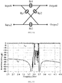
- FIG. 10 is an abstract circuit diagram of a filter with a Lattice topology (a common structure) in the related art.
- Input1 and Input2 represent input ports
- Output1 and Output2 represent output ports
- Rp1 and Rp2 represent parallel resonators
- Rs1 and Rs2 represent series resonators.
- FIG. 11 shows a graph of frequency-insertion loss of common filters in FIGS. 9 and 10 .
- a reflection coefficient within a passband is low, but is high beyond the passband (in a stopband) with strong reflection. That is, an input electrical signal at the input terminal is transmitted to the output terminal if it is located within the passband, it is, and it is totally reflected to the input terminal without signal output at the output terminal if it is located within the stopband.
- the reflected signal with a high power is returned to the input terminal, the reflected signal may disadvantageously affect subsequent circuits after being transmitted back to the input terminal, thereby destroying stability of the active circuit.
- inter-stage reflection degrades the response of the filter
- the inter-stage reflection cannot be enhanced by direct cascading
- performance of a terminal mixer at an out-of-band port of a reflective filter is sensitive, and performance of the system is influenced by a reactive terminal within its stopband.
- a reflectionless filter system is demanded increasingly.
- a filter having a traditional bulk acoustic wave resonator cannot be implemented for some special situations which require low reflection or even no reflection in a full band.
- it is greatly required to develop and realize a reflectionless filter based on a bulk acoustic wave resonator with customized response, which is also an acknowledged technical problem in this industry.
- a bulk acoustic wave resonator that includes a symmetrical two-port circuit.
- the symmetrical two-port circuit includes a plurality of series resonator branches and a plurality of parallel resonator branches.
- Each of the plurality of series resonator branches is provided with a series resonator unit, and each of the plurality of parallel resonator branches is provided with a parallel resonator unit.
- the series resonator unit includes a parallel module formed by a bulk acoustic wave resonator and an inductor that are connected in parallel to each other, and the parallel resonator units of at least two of the plurality of parallel resonator branches each include a series module formed by a bulk acoustic wave resonator and an inductor that are connected in series to each other.
- the series resonator unit includes a series module formed by a bulk acoustic wave resonator and an inductor that are connected in series to each other
- the parallel resonator units of at least two of the plurality of parallel resonator branches each include a parallel module formed by a bulk acoustic wave resonator and an inductor that are connected in parallel to each other.
- an electronic device which includes the reflectionless filter described above.
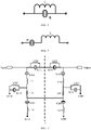
- FIG. 1 is a circuit structural diagram of a parallel module formed by a bulk acoustic wave resonator R and an inductor L that are connected to each other in parallel according to an exemplary embodiment of the present disclosure.
- FIG. 2 is a circuit structural diagram of a series module formed by a bulk acoustic wave resonator R and an inductor L that are connected to each other in series according to an exemplary embodiment of the present disclosure.
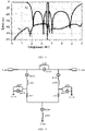
- FIG. 3 is a circuit structural diagram of a reflectionless filter according to an exemplary embodiment of the present disclosure.
- the circuit structure is divided into a left portion and a right portion by a dotted line B-B' in FIG. 3 , which are symmetrical relative to each other.
- the circuit structure includes an input port (Input) and an output port (Output).
- the left portion includes four bulk acoustic wave resonators R101, R102, R103 and R104, four inductors L101, L102, L103 and L104, and a resistor r101.
- the resonator R101, the inductor L101, the resonator R103 and the inductor L103 form a parallel module to achieve parallel inductance on the bulk acoustic wave resonator.
- the resonator R102, the inductor L102, the resonator R104 and the inductor L104 form a series module to achieve series inductance on the bulk acoustic wave resonator.
- the left-right symmetry of the circuit structure means not only structural symmetry, but also numerical symmetry. That is, values of components arranged at symmetrical positions are the same.
- the left portion of the circuit structure includes a first series resonator unit, a first parallel resonator unit, a second parallel resonator unit, a resistance element or resistor r101, and a third parallel resonator unit.
- the first series resonator unit includes a parallel module formed by the bulk acoustic wave resonator R101 and the inductor L101, which are connected in parallel to each other.
- the first parallel resonator unit includes a series module formed by the bulk acoustic wave resonator R102 and the inductor L102, which are connected in series to each other.
- the second parallel resonator unit includes a series module formed by the bulk acoustic wave resonator R104 and the inductor L104, which are connected in series to each other.
- One end of the first parallel resonator unit is connected between the input port and the first series resonator unit, and the other end of the first parallel resonator unit is connected to one end of the resistance element r101.
- the other end of the resistance element r101 is connected to one end of the second parallel resonator unit, and the other end of the second parallel resonator unit is grounded (GND).
- the third parallel resonator unit includes a parallel module formed by the bulk acoustic wave resonator R103 and the inductor L103, which are connected in parallel to each other.
- One end of the third parallel resonator unit is connected between the other end of the first parallel resonator unit and the one end of the resistance element r101, and the other end of the third parallel resonator unit is grounded.
- the other end of the resistance element r101 and the other end of a resistance element r201 are electrically connected to each other.
- FIG. 4 shows a graph of transmission characteristics and reflection characteristics of a reflectionless filter based on a structure in FIG. 3 according to an embodiment of the present disclosure.
- return loss of a port reflection coefficient S11 of a single-stage filter in a full band is -35 dB or less.
- the circuit structure in FIG. 3 can achieve low-pass, band-pass, and high-pass characteristics.
- FIG. 5 is a circuit structural diagram of a reflectionless filter according to another exemplary embodiment of the present disclosure.
- FIG. 5 is a simplified diagram of circuit elements of the circuit structure in FIG. 3 .
- the two parallel modules connected between the two ports are combined into one parallel module, and second ends of the resistance elements or the resistors are connected to one parallel resonator unit.
- the circuit structure in FIG. 5 includes a first series resonator unit, a first parallel resonator unit, a first resistance element r301, a second parallel resonator unit, a second resistance element r302, a third parallel resonator unit, a fourth parallel resonator unit, and a fifth parallel resonator unit.
- the first series resonator unit is connected between an input port and an output port.
- the first series resonator unit includes a parallel module formed by a bulk acoustic wave resonator R301 and an inductor L301, which are connected in parallel to each other.
- the first parallel resonator unit includes a series module formed by a bulk acoustic wave resonator R302 and an inductor L302, which are connected in series to each other.
- One end of the first parallel resonator unit is connected between the input port and the first series resonator unit, and the other end of the first parallel resonator unit is connected to one end of the first resistance element r301.
- the second parallel resonator unit includes a series module formed by a bulk acoustic wave resonator R304 and an inductor L304, which are connected in series to each other.
- One end of the second parallel resonator unit is connected between the output port and the first series resonator unit, and the other end of the second parallel resonator unit is connected to one end of the second resistance element r302.
- the third parallel resonator unit includes a series module formed by a bulk acoustic wave resonator R306 and an inductor L306, which are connected in series to each other.
- One end of the third parallel resonator unit is connected to the other end of the first resistor r301 and the other end of the second resistor r302, and the other end of the third parallel resonator unit is grounded.
- the fourth parallel resonator unit includes a parallel module formed by a bulk acoustic wave resonator R303 and an inductor L303, which are connected in parallel to each other.
- One end of the fourth parallel resonator unit is connected between the other end of the first parallel resonator unit and the one end of the first resistance element, and the other end of the fourth parallel resonator unit is grounded.
- the fifth parallel resonator unit includes a parallel module formed by a bulk acoustic wave resonator R305 and an inductor L305, which are connected in parallel to each other.
- One end of the fifth parallel resonator unit is connected between the other end of the second parallel resonator unit and the one end of the second resistance element, and the other end of the fifth parallel resonator unit is grounded.
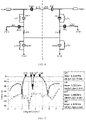
- FIG. 6 is a circuit structural diagram of a reflectionless filter according to yet another exemplary embodiment of the present disclosure.
- FIG. 6 differs from FIG. 3 in that positions of the series modules and the parallel modules in FIG. 3 and FIG. 6 are interchanged.
- the circuit structure is divided into a left portion and a right portion by a dotted line B-B' in FIG. 6 , which are symmetrical relative to each other.
- the circuit structure includes an input port (Input) and an output port (Output).
- the left portion includes four bulk acoustic wave resonators R401, R402, R403 and R404, four inductors L401, L402, L403 and L404, and a resistor r401.
- the resonator R401, the inductor L401, the resonator R403 and the inductor L403 form a series module to achieve series inductance on the bulk acoustic wave resonator.
- the resonator R402, the inductor L402, the resonator R404 and the inductor L404 form a parallel module to achieve parallel inductance on the bulk acoustic wave resonator.
- the left portion of the circuit structure includes a first series resonator unit, a first parallel resonator unit, a second parallel resonator unit, a resistance element or resistor r401, and a third parallel resonator unit.
- the first series resonator unit includes a series module formed by the bulk acoustic wave resonator R401 and the inductor L401, which are connected in series to each other.
- the first parallel resonator unit includes a parallel module formed by the bulk acoustic wave resonator R402 and the inductor L402, which are connected in parallel to each other.
- the second parallel resonator unit includes a parallel module formed by the bulk acoustic wave resonator R404 and the inductor L404, which are connected in parallel to each other.
- One end of the first parallel resonator unit is connected between the input port and the first series resonator unit, and the other end of the first parallel resonator unit is connected to one end of the resistance element r401.
- the other end of the resistance element r401 is connected to one end of the second parallel resonator unit, and the other end of the second parallel resonator unit is grounded (GND).
- the third parallel resonator unit includes a series module formed by the bulk acoustic wave resonator R403 and the inductor L403, which are connected in series to each other.
- One end of the third parallel resonator unit is connected between the other end of the first parallel resonator unit and the one end of the resistance element r401, and the other end of the third parallel resonator unit is grounded.
- the other end of the resistance element r401 and the other end of a resistance element r501 are electrically connected to each other.
- FIG. 7 shows a graph of transmission characteristics and reflection characteristics of a reflectionless filter based on a structure in FIG. 7 according to an embodiment of the present disclosure.
- return loss of a port reflection coefficient S11 of a single-stage filter in a frequency band of 0 to 6.5 GHz is -35 dB or less.
- the circuit structure in FIG. 6 can realize dual-bandpass characteristics.
- the filter in FIG. 6 is a dual-bandpass filter.
- FIG. 8 is a circuit structural diagram of a reflectionless filter according to another exemplary embodiment of the present disclosure.
- FIG. 8 is a simplified diagram of circuit elements of the circuit structure in FIG. 6 .
- two series modules are combined into one series module, and second ends of resistance elements or resistors are connected to a parallel resonator unit.
- the circuit structure in FIG. 8 includes a first series resonator unit, a first parallel resonator unit, a first resistance element r401, a second parallel resonator unit, a second resistance element r501, a third parallel resonator unit, a fourth parallel resonator unit, and a fifth parallel resonator unit.
- the first series resonator unit is connected between an input port and an output port.
- the first series resonator unit includes a series module formed by a bulk acoustic wave resonator R401 and an inductor L401, which are connected in series to each other.
- the first parallel resonator unit includes a parallel module formed by a bulk acoustic wave resonator R402 and an inductor L402, which are connected in parallel to each other.
- One end of the first parallel resonator unit is connected between the input port and the first series resonator unit, and the other end of the first parallel resonator unit is connected to one end of the first resistance element r401.
- the second parallel resonator unit includes a parallel module formed by a bulk acoustic wave resonator R502 and an inductor L502, which are connected in parallel to each other.
- One end of the second parallel resonator unit is connected between the output port and the first series resonator unit, and the other end of the second parallel resonator unit is connected to one end of the second resistance element r501.
- the third parallel resonator unit includes a parallel module formed by a bulk acoustic wave resonator R404 and an inductor L404, which are connected in parallel to each other.
- One end of the third parallel resonator unit is connected to the other end of the first resistor r401 and the other end of the second resistance element r501, and the other end of the third parallel resonator unit is grounded.
- the fourth parallel resonator unit includes a series module formed by a bulk acoustic wave resonator R403 and an inductor L403, which are connected in series to each other.
- One end of the fourth parallel resonator unit is connected between the other end of the first parallel resonator unit and the one end of the first resistance element, and the other end of the fourth parallel resonator unit is grounded.
- the fifth parallel resonator unit includes a series module formed by a bulk acoustic wave resonator R503 and an inductor L503, which are connected in series to each other.
- One end of the fifth parallel resonator unit is connected between the other end of the second parallel resonator unit and the one end of the second resistance element, and the other end of the fifth parallel resonator unit is grounded.
- the reflectionless filter according to the present disclosure can be used in combination with an LC reflectionless bandpass filter in the related art. Accordingly, the present disclosure provides a filter assembly that includes an input port, an output port, an LC reflectionless bandpass filter, and the above reflectionless filter. At least one reflectionless filter (or a plurality of reflectionless filters in cascaded form) and the LC bandpass filter are sequentially connected in series between the input port and the output port.
- resistance of the resistance elements are equivalent to or the same as port impedance at the ports.
- the port impedance is 50 Ohm
- the resistance of the two resistance elements are also 50 Ohm.
- Equivalent herein means that a difference between them is no more than 10%.
- a plurality of the reflectionless filters described above are cascaded to form a cascaded unit of the reflectionless filters.
Landscapes
- Physics & Mathematics (AREA)
- Acoustics & Sound (AREA)
- Chemical & Material Sciences (AREA)
- Crystallography & Structural Chemistry (AREA)
- Surface Acoustic Wave Elements And Circuit Networks Thereof (AREA)
- Piezo-Electric Or Mechanical Vibrators, Or Delay Or Filter Circuits (AREA)
Applications Claiming Priority (2)
| Application Number | Priority Date | Filing Date | Title |
|---|---|---|---|
| CN201911344202.7A CN111262550B (zh) | 2019-12-24 | 2019-12-24 | 无反射滤波器和电子设备 |
| PCT/CN2020/088718 WO2021128694A1 (zh) | 2019-12-24 | 2020-05-06 | 无反射滤波器和电子设备 |
Publications (2)
| Publication Number | Publication Date |
|---|---|
| EP4084332A1 true EP4084332A1 (de) | 2022-11-02 |
| EP4084332A4 EP4084332A4 (de) | 2023-07-05 |
Family
ID=70953954
Family Applications (1)
| Application Number | Title | Priority Date | Filing Date |
|---|---|---|---|
| EP20907583.7A Pending EP4084332A4 (de) | 2019-12-24 | 2020-05-06 | Reflexionsfreies filter und elektronisches gerät |
Country Status (3)
| Country | Link |
|---|---|
| EP (1) | EP4084332A4 (de) |
| CN (1) | CN111262550B (de) |
| WO (1) | WO2021128694A1 (de) |
Cited By (2)
| Publication number | Priority date | Publication date | Assignee | Title |
|---|---|---|---|---|
| EP4383565A1 (de) * | 2022-12-07 | 2024-06-12 | Qorvo US, Inc. | Akustische filter mit verbessertem reflexionsverlust |
| US12500566B2 (en) | 2022-07-26 | 2025-12-16 | Chengdu Boe Optoelectronics Technology Co., Ltd. | Filter, radio frequency device and electronic apparatus |
Families Citing this family (3)
| Publication number | Priority date | Publication date | Assignee | Title |
|---|---|---|---|---|
| CN112909461B (zh) * | 2021-01-25 | 2021-08-03 | 北京邮电大学 | 一种互补双工结构全频段吸收双频带通滤波器 |
| CN115051680B (zh) * | 2021-03-08 | 2026-01-09 | 诺思(天津)微系统有限责任公司 | 具有单晶和多晶体声波谐振器的滤波器及电子设备 |
| CN117375573B (zh) * | 2023-12-07 | 2024-04-12 | 华南理工大学 | 无反射声波滤波器单元、无反射声波滤波器及制作方法 |
Family Cites Families (9)
| Publication number | Priority date | Publication date | Assignee | Title |
|---|---|---|---|---|
| DE10342991A1 (de) * | 2002-09-18 | 2004-04-22 | Nrs Technologies Inc. | SAW-Filter |
| JP2007074698A (ja) * | 2005-08-08 | 2007-03-22 | Fujitsu Media Device Kk | 分波器及びラダー型フィルタ |
| US7339445B2 (en) * | 2005-10-07 | 2008-03-04 | Infineon Technologies Ag | BAW duplexer without phase shifter |
| US20070159274A1 (en) * | 2005-12-26 | 2007-07-12 | Tatsunori Onzuka | SAW filter and portable terminal |
| US8392495B2 (en) * | 2009-02-09 | 2013-03-05 | Associated Universities, Inc. | Reflectionless filters |
| CN103259501B (zh) * | 2013-05-31 | 2016-06-29 | 电子科技大学 | 一种通信系统用带阻滤波器 |
| CN107078708B (zh) * | 2014-06-25 | 2021-02-09 | 联合大学公司 | 子网络增强型无反射滤波器拓扑 |
| US10263599B2 (en) * | 2015-12-21 | 2019-04-16 | Qorvo Us, Inc. | Bulk acoustic wave (BAW) filter with coupled inductors |
| CN107342749B (zh) * | 2017-06-05 | 2020-08-28 | 锐迪科微电子科技(上海)有限公司 | 一种带通滤波器 |
-
2019
- 2019-12-24 CN CN201911344202.7A patent/CN111262550B/zh active Active
-
2020
- 2020-05-06 EP EP20907583.7A patent/EP4084332A4/de active Pending
- 2020-05-06 WO PCT/CN2020/088718 patent/WO2021128694A1/zh not_active Ceased
Cited By (3)
| Publication number | Priority date | Publication date | Assignee | Title |
|---|---|---|---|---|
| US12500566B2 (en) | 2022-07-26 | 2025-12-16 | Chengdu Boe Optoelectronics Technology Co., Ltd. | Filter, radio frequency device and electronic apparatus |
| EP4383565A1 (de) * | 2022-12-07 | 2024-06-12 | Qorvo US, Inc. | Akustische filter mit verbessertem reflexionsverlust |
| US12500567B2 (en) | 2022-12-07 | 2025-12-16 | Qorvo Us, Inc. | Acoustic filters with improved return loss |
Also Published As
| Publication number | Publication date |
|---|---|
| EP4084332A4 (de) | 2023-07-05 |
| CN111262550A (zh) | 2020-06-09 |
| WO2021128694A1 (zh) | 2021-07-01 |
| CN111262550B (zh) | 2021-04-16 |
Similar Documents
| Publication | Publication Date | Title |
|---|---|---|
| EP4084332A1 (de) | Reflexionsfreies filter und elektronisches gerät | |
| US9165101B2 (en) | Network synthesis design of microwave acoustic wave filters | |
| US10873318B2 (en) | Filter circuits having acoustic wave resonators in a transversal configuration | |
| US3879690A (en) | Distributed transmission line filter | |
| US10277198B2 (en) | High power and low loss acoustic filter | |
| CN216794959U (zh) | 切比雪夫带通滤波电路和射频前端模组 | |
| CN103413993A (zh) | 分布式微型带通平衡滤波器 | |
| CN104716926A (zh) | 压电滤波器 | |
| CN112953432A (zh) | 一种带阻滤波器 | |
| CN212305276U (zh) | 带通滤波器和滤波器 | |
| CN213402952U (zh) | 一种滤波器结构 | |
| CN118214390A (zh) | 滤波器、多工器以及射频前端模组 | |
| CN210093186U (zh) | 一种对偶互补式双工滤波器 | |
| KR100752733B1 (ko) | 박막 공진기 필터 및 박막 공진기 필터 설계 방법 | |
| EP1126604A2 (de) | Filter mit Dünnfilmresonatoren und einer Induktanz | |
| CN216390937U (zh) | Wifi 6e带通滤波器、相关设备及芯片 | |
| US6064281A (en) | Semi-lumped bandpass filter | |
| CN111988007A (zh) | 带通滤波器和滤波器 | |
| CN114337594B (zh) | 滤波电路和双工器 | |
| JP2853702B2 (ja) | 誘電体フィルタ | |
| JP3230623B2 (ja) | 複合フィルタ | |
| CN222366255U (zh) | 低通滤波电路、低通滤波器和电子设备 | |
| US12184257B2 (en) | Hybrid signal filter | |
| CN204011614U (zh) | 叉指型开路线微带滤波器 | |
| CN217957049U (zh) | 一种滤波器和射频前端模组 |
Legal Events
| Date | Code | Title | Description |
|---|---|---|---|
| STAA | Information on the status of an ep patent application or granted ep patent |
Free format text: STATUS: THE INTERNATIONAL PUBLICATION HAS BEEN MADE |
|
| PUAI | Public reference made under article 153(3) epc to a published international application that has entered the european phase |
Free format text: ORIGINAL CODE: 0009012 |
|
| STAA | Information on the status of an ep patent application or granted ep patent |
Free format text: STATUS: REQUEST FOR EXAMINATION WAS MADE |
|
| 17P | Request for examination filed |
Effective date: 20220725 |
|
| AK | Designated contracting states |
Kind code of ref document: A1 Designated state(s): AL AT BE BG CH CY CZ DE DK EE ES FI FR GB GR HR HU IE IS IT LI LT LU LV MC MK MT NL NO PL PT RO RS SE SI SK SM TR |
|
| DAV | Request for validation of the european patent (deleted) | ||
| DAX | Request for extension of the european patent (deleted) | ||
| REG | Reference to a national code |
Ref country code: DE Ref legal event code: R079 Free format text: PREVIOUS MAIN CLASS: H03H0009170000 Ipc: H03H0009540000 |
|
| A4 | Supplementary search report drawn up and despatched |
Effective date: 20230605 |
|
| RIC1 | Information provided on ipc code assigned before grant |
Ipc: H03H 9/60 20060101ALI20230530BHEP Ipc: H03H 9/58 20060101ALI20230530BHEP Ipc: H03H 9/56 20060101ALI20230530BHEP Ipc: H03H 9/54 20060101AFI20230530BHEP |