EP4084385B1 - Procédé de commutation d'antenne, dispositif terminal, et dispositif de communication - Google Patents
Procédé de commutation d'antenne, dispositif terminal, et dispositif de communication Download PDFInfo
- Publication number
- EP4084385B1 EP4084385B1 EP20920574.9A EP20920574A EP4084385B1 EP 4084385 B1 EP4084385 B1 EP 4084385B1 EP 20920574 A EP20920574 A EP 20920574A EP 4084385 B1 EP4084385 B1 EP 4084385B1
- Authority
- EP
- European Patent Office
- Prior art keywords
- srs resource
- srs
- resource set
- resources
- set group
- Prior art date
- Legal status (The legal status is an assumption and is not a legal conclusion. Google has not performed a legal analysis and makes no representation as to the accuracy of the status listed.)
- Active
Links
Images

Classifications
-
- H—ELECTRICITY
- H04—ELECTRIC COMMUNICATION TECHNIQUE
- H04B—TRANSMISSION
- H04B7/00—Radio transmission systems, i.e. using radiation field
- H04B7/02—Diversity systems; Multi-antenna system, i.e. transmission or reception using multiple antennas
- H04B7/04—Diversity systems; Multi-antenna system, i.e. transmission or reception using multiple antennas using two or more spaced independent antennas
- H04B7/08—Diversity systems; Multi-antenna system, i.e. transmission or reception using multiple antennas using two or more spaced independent antennas at the receiving station
- H04B7/0802—Diversity systems; Multi-antenna system, i.e. transmission or reception using multiple antennas using two or more spaced independent antennas at the receiving station using antenna selection
- H04B7/0805—Diversity systems; Multi-antenna system, i.e. transmission or reception using multiple antennas using two or more spaced independent antennas at the receiving station using antenna selection with single receiver and antenna switching
- H04B7/0814—Diversity systems; Multi-antenna system, i.e. transmission or reception using multiple antennas using two or more spaced independent antennas at the receiving station using antenna selection with single receiver and antenna switching based on current reception conditions, e.g. switching to different antenna when signal level is below threshold
-
- H—ELECTRICITY
- H04—ELECTRIC COMMUNICATION TECHNIQUE
- H04L—TRANSMISSION OF DIGITAL INFORMATION, e.g. TELEGRAPHIC COMMUNICATION
- H04L5/00—Arrangements affording multiple use of the transmission path
- H04L5/003—Arrangements for allocating sub-channels of the transmission path
- H04L5/0048—Allocation of pilot signals, i.e. of signals known to the receiver
- H04L5/0051—Allocation of pilot signals, i.e. of signals known to the receiver of dedicated pilots, i.e. pilots destined for a single user or terminal
-
- H—ELECTRICITY
- H04—ELECTRIC COMMUNICATION TECHNIQUE
- H04B—TRANSMISSION
- H04B7/00—Radio transmission systems, i.e. using radiation field
- H04B7/02—Diversity systems; Multi-antenna system, i.e. transmission or reception using multiple antennas
- H04B7/04—Diversity systems; Multi-antenna system, i.e. transmission or reception using multiple antennas using two or more spaced independent antennas
- H04B7/06—Diversity systems; Multi-antenna system, i.e. transmission or reception using multiple antennas using two or more spaced independent antennas at the transmitting station
- H04B7/0686—Hybrid systems, i.e. switching and simultaneous transmission
- H04B7/0691—Hybrid systems, i.e. switching and simultaneous transmission using subgroups of transmit antennas
-
- H—ELECTRICITY
- H04—ELECTRIC COMMUNICATION TECHNIQUE
- H04B—TRANSMISSION
- H04B7/00—Radio transmission systems, i.e. using radiation field
- H04B7/02—Diversity systems; Multi-antenna system, i.e. transmission or reception using multiple antennas
- H04B7/04—Diversity systems; Multi-antenna system, i.e. transmission or reception using multiple antennas using two or more spaced independent antennas
- H04B7/08—Diversity systems; Multi-antenna system, i.e. transmission or reception using multiple antennas using two or more spaced independent antennas at the receiving station
- H04B7/0868—Hybrid systems, i.e. switching and combining
- H04B7/0874—Hybrid systems, i.e. switching and combining using subgroups of receive antennas
-
- H—ELECTRICITY
- H04—ELECTRIC COMMUNICATION TECHNIQUE
- H04L—TRANSMISSION OF DIGITAL INFORMATION, e.g. TELEGRAPHIC COMMUNICATION
- H04L5/00—Arrangements affording multiple use of the transmission path
- H04L5/0001—Arrangements for dividing the transmission path
- H04L5/0014—Three-dimensional division
- H04L5/0023—Time-frequency-space
-
- H—ELECTRICITY
- H04—ELECTRIC COMMUNICATION TECHNIQUE
- H04L—TRANSMISSION OF DIGITAL INFORMATION, e.g. TELEGRAPHIC COMMUNICATION
- H04L5/00—Arrangements affording multiple use of the transmission path
- H04L5/003—Arrangements for allocating sub-channels of the transmission path
- H04L5/0053—Allocation of signalling, i.e. of overhead other than pilot signals
-
- H—ELECTRICITY
- H04—ELECTRIC COMMUNICATION TECHNIQUE
- H04L—TRANSMISSION OF DIGITAL INFORMATION, e.g. TELEGRAPHIC COMMUNICATION
- H04L5/00—Arrangements affording multiple use of the transmission path
- H04L5/0091—Signalling for the administration of the divided path, e.g. signalling of configuration information
- H04L5/0094—Indication of how sub-channels of the path are allocated
-
- H—ELECTRICITY
- H04—ELECTRIC COMMUNICATION TECHNIQUE
- H04W—WIRELESS COMMUNICATION NETWORKS
- H04W52/00—Power management, e.g. Transmission Power Control [TPC] or power classes
- H04W52/04—Transmission power control [TPC]
- H04W52/06—TPC algorithms
- H04W52/14—Separate analysis of uplink or downlink
- H04W52/146—Uplink power control
-
- H—ELECTRICITY
- H04—ELECTRIC COMMUNICATION TECHNIQUE
- H04W—WIRELESS COMMUNICATION NETWORKS
- H04W52/00—Power management, e.g. Transmission Power Control [TPC] or power classes
- H04W52/04—Transmission power control [TPC]
- H04W52/30—Transmission power control [TPC] using constraints in the total amount of available transmission power
- H04W52/32—TPC of broadcast or control channels
- H04W52/325—Power control of control or pilot channels
Definitions
- the present disclosure relates to the communication field, and more particularly, to an antenna switching method, a terminal device, and a communication device.
- MIMO Multiple Input Multiple Output
- various kinds of gains can be obtained, e.g. a space diversity gain, a beamforming gain (also referred to as a pre-coding gain), a space multiplexing gain.
- a transmitter needs to determine a beamforming matrix/pre-coding matrix for signal transmission.
- a basic requirement is to obtain some form of channel information of a transmission channel corresponding to the terminal.
- a channel reciprocity method in order to obtain the channel information of the transmission channel of the terminal, a channel reciprocity method may be adopted.
- the channel reciprocity method needs the terminal to transmit a Sounding Reference Signal (SRS) according to configuration information from a base station, and the configuration information is related to an antenna switching configuration of the terminal.
- the antenna switching configuration may be represented by xTyR or txry, wherein x and y are positive integers, specifically indicating that the SRS may be transmitted through x antenna ports, and y corresponds to the number of all or part of the receiving antennas of a terminal device.
- the terminal may improve a downlink receiving capability with more receiving antennas.
- the antenna switching configuration, xTyR, of the terminal device has a large value of y, for example, y is greater than 4. At present, there is no suitable configuration mode to support antenna switching for these terminal devices which have more (such as more than 4) receiving antennas.
- an SRS configuration is received from a network in which at least four antennas of a scheduled entity are configured based on the SRS configuration.
- the SRS configuration configures at least one antenna to simultaneously support SRS antenna switching and an uplink (UL) multiple-input multiple-output (MIMO) communication.
- An SRS communication is then transmitted according to the SRS configuration.
- a transmission capability reporting is received form a scheduled entity comprising at least four antennas.
- a determination is then made of whether the scheduled entity may simultaneously support SRS antenna switching and an UL MIMO communication.
- An SRS configuration is then generated for the scheduled entity based on the determination in which a default SRS configuration configures at least one antenna to simultaneously support the SRS antenna switching and the UL MIMO communication.
- WO 2018/126474 A1 provides methods and apparatus for transmitting multiplexed sounding reference signal (SRS) ports in communication systems operating according to new radio (NR) technologies.
- An exemplary method includes obtaining an indication of a technique to use in transmitting sounding reference signals (SRS) via five or more antenna ports in one slot and transmitting the SRS via the five or more antenna ports according to the indicated technique.
- SRS sounding reference signals
- EP 4042647 A1 (QUALCOMM INC [US]), 17 August 2022 , provides methods, devices and systems for channel sounding for wireless communications. Some implementations more specifically relate to scheduling sounding reference signal (SRS) resource sets for wireless devices having more than (4) receive (RX) antenna ports.
- a base station may determine an antenna switching capability of a user equipment (UE). The antenna switching capability indicates a number of RX antenna ports of the UE. The base station schedules a number of SRS resource sets for the UE based at least in part on the number of RX antenna ports in excess of four. For example, the number of RX antenna ports may be equal to (8). As another example, the number of RX antenna ports may be equal to (6). The base station further receives, from the UE, uplink transmissions of one or more SRS resources for each of the scheduled SRS resource sets.
- Embodiments of the present disclosure provide an antenna switching method, and a terminal device, as defined in the appended claims, which can achieve antenna switching of a terminal device having many (e.g., more than four) receiving antennas.
- the present disclosure also discloses an antenna switching method, defined by independent claim 1, the method carried out by a terminal device, configured to be operable in a radio communication system, according to the 3GPP standard, the method comprising: receiving configuration information sent by a network device; wherein the configuration information indicates M Sounding Reference Signal, SRS, resource set groups, each of which contains at least one SRS resource set; wherein M is a positive integer; each of the SRS resource set groups corresponds to a corresponding antenna switching configuration that supports the first terminal device to have more than four receiving antennas; wherein, the antenna switching configuration is represented by xTyR; wherein y is an integer greater than 4, and x is a positive integer; the xTyR indicates that an SRS supports transmission by x antenna ports, and y corresponds to a number of all or part of receiving antennas of the first terminal device; wherein the antenna switching method further comprises: reporting an antenna switching capability that supports the antenna switching configuration represented by the xTyR; wherein the antenna switching method further comprises: when a plurality
- the present disclosure also discloses a terminal device, according to independent claim 13, and fully corresponding to the independent method claim 1.
- GSM Global System of Mobile Communication
- CDMA Code Division Multiple Access
- WCDMA Wideband Code Division Multiple Access
- GPRS General Packet Radio Service
- LTE Long Term Evolution
- LTE-A Advanced Long Term Evolution
- NR New Radio
- UMTS Universal Mobile Telecommunications System
- WLAN Wireless Local Area Networks
- WiFi Wireless Fidelity
- 5G next generation communication
- D2D Device to Device
- M2M Machine to Machine
- MTC Machine Type Communication
- V2V Vehicle to Vehicle
- a communication system in the embodiments of the present disclosure may be applied to a Carrier Aggregation (CA) scenario, or a Dual Connectivity (DC) scenario, or a Standalone (SA) network deployment scenario.
- CA Carrier Aggregation
- DC Dual Connectivity
- SA Standalone
- a frequency spectrum to which an embodiment of the present disclosure is applied is not limited.
- the embodiment of the present disclosure may be applied to a licensed spectrum, or an unlicensed spectrum.
- the terminal device may also be referred to as a User Equipment (UE), an access terminal, a subscriber unit, a subscriber station, a mobile station, a mobile platform, a remote station, a remote terminal, a mobile device, a user terminal, a terminal, a wireless communication device, a user agent, or a user apparatus, etc.
- UE User Equipment
- the terminal device may be a STATION (ST) in the WLAN, or may be a cellular phone, a cordless phone, a Session Initiation Protocol (SIP) phone, a Wireless Local Loop (WLL) station, a Personal Digital Assistant (PDA) device, a handheld device with a wireless communication function, a computing device, or another processing device connected to a wireless modem, a vehicle-mounted device, a wearable device, or a next generation communication system, e.g., a terminal device in an NR network, or a terminal device in a future evolved Public Land Mobile Network (PLMN).
- ST STATION
- PDA Personal Digital Assistant
- the terminal device may also be a wearable device.
- the wearable device may also be referred to as a wearable smart device, which is a general term of wearable devices, e.g., glasses, gloves, a watch, clothing, or shoes, which are intelligent designed for daily wear and developed by using wearing technologies.
- the wearable device is a portable device that is worn directly on a body, or integrated into clothes or an accessory of a user.
- the wearable device is not only a hardware device, but also achieves powerful functions through software support, data interaction, and cloud interaction.
- Generalized wearable smart devices include a device that is full functioned, large sized, and may achieve complete or partial functions without relying on a smart phone, such as a smart watch, or smart glasses, and include a device that only focuses on a kind of application function, and needs to be used in conjunction with another device such as a smart phone, such as various types of smart bracelets, smart jewelry, or the like, for monitoring physical signs.
- the network device may be a device configured to communicate with a mobile device, and may be an Access Point (AP) in WLAN, or a Base Transceiver Station (BTS) in GSM or CDMA, or may be a NodeB (NB) in WCDMA, or an Evolutional Node B (eNB or eNodeB) in LTE, or a relay station or an access point, or a vehicle-mounted device, a wearable device, a network device (gNB) in an NR network, or a network device in a future evolved PLMN network, etc.
- AP Access Point
- BTS Base Transceiver Station
- NB NodeB
- eNB or eNodeB Evolutional Node B
- gNB network device
- gNB network device
- gNB network device in an NR network
- future evolved PLMN network etc.
- a network device provides a service for a cell
- a terminal device communicates with the network device through a transmission resource (e.g., a frequency domain resource, or referred to as a spectrum resource) used for the cell
- the cell may be a cell corresponding to the network device (e.g., a base station).
- the cell may belong to a macro base station, or a base station corresponding to a Small cell.
- the Small cell here may include: a Metro cell, a Micro cell, a Pico cell, or a Femto cell, etc. These Small cells have characteristics of a small coverage range and a low transmission power, and are suitable for providing high-speed data transmission services.
- FIG. 1 exemplarily illustrates one network device 110 and two terminal devices 120.
- a wireless communication system 100 may include a plurality of network devices 110, and another quantity of terminal devices may be included within a coverage range of each network device 110, which is not limited in the embodiments of the present disclosure.
- Embodiments of the present disclosure may be applied to one terminal device 120 and one network device 110, and may also be applied to one terminal device 120 and another terminal device 120.
- the wireless communication system 100 may further include another network entity such as a Mobility Management Entity (MME), and an Access and Mobility Management Function (AMF), which is not limited in the embodiments of the present disclosure.
- MME Mobility Management Entity
- AMF Access and Mobility Management Function
- FIG. 2 is a flow chart of an implementation of an antenna switching method according to an embodiment of the present disclosure, including the following act S210.
- a first terminal device receives configuration information, the configuration information indicates M Sounding Reference Signal (SRS) resource set groups, each of which contains at least one SRS resource set; wherein M is a positive integer; and each SRS resource set group corresponds to a corresponding antenna switching configuration that supports a first terminal device to have more than four receiving antennas.
- SRS Sounding Reference Signal
- the antenna switching configuration is represented by xTyR; wherein y is an integer greater than 4 and x is a positive integer; xTyR indicates that the SRS may be transmitted by x antenna ports, y corresponds to the number of all or part of receiving antennas of the first terminal device.
- the antenna port may refer to a transmitting antenna.
- the SRS resource set group may represent one or more SRS resource sets.
- One or more SRS resource sets may be regarded as one whole, which is referred to as for short an SRS resource set group, and it is not necessary to define one or more SRS resource sets as an SRS resource set group.
- the SRS resource set group contains one SRS resource set. That is, the corresponding SRS resource set group is equal to the SRS resource set (the SRS resource set group contains only one SRS resource set).
- resourceType fields corresponding to SRS resource sets in different SRS resource set groups are configured to be different values.
- resourceType fields corresponding to SRS resource sets in different SRS resource set groups are configured to be a same value or different values.
- the configuration information is sent from a network device to the first terminal device.
- the configuration information is sent from another terminal device (such as a second terminal device) to the first terminal device, which can better support communication between terminals, such as Device-to-Device (D2D) communication, Vehicle to Everything (V2X) communication, or Sidelink communication.
- D2D Device-to-Device
- V2X Vehicle to Everything
- Sidelink communication such as Sidelink communication
- the first terminal device reports an antenna switching capability that supports the antenna switching configuration represented by the xTyR.
- the antenna switching capability can also be referred to as an antenna switching capability corresponding to xTyR.
- the first terminal device may report the antenna switching capability via Radio Resource Control (RRC) signaling.
- RRC Radio Resource Control
- M 1, 2, or 3 therefore more configurations can be supported, flexibility of a system configuration can be improved, and system performance can be improved.
- the M SRS resource set groups contain at least one first SRS resource set group, and the first SRS resource set group corresponds to an antenna switching configuration corresponding to 8T8R; wherein, the first SRS resource set group contains one SRS resource set; each SRS resource set contains one SRS resource, and each SRS resource is configured with eight SRS ports.
- the M SRS resource set groups contain at least one second SRS resource set group, and the second SRS resource set group corresponds to an antenna switching configuration corresponding to 4T8R; wherein, the second SRS resource set group contains one SRS resource set, each SRS resource set contains two SRS resources, and each SRS resource is configured with four SRS ports.
- the M SRS resource set groups contain at least one third SRS resource set group, and the third SRS resource set group corresponds to an antenna switching configuration corresponding to 2T8R; if a resource Type field corresponding to an SRS resource set in the third SRS resource set group is configured to be periodic or semipersistent, the third SRS resource set group contains one SRS resource set, and the SRS resource set contains four SRS resources, and each SRS resource is configured with two SRS ports.
- the M SRS resource set groups contain at least one fourth SRS resource set group, and the fourth SRS resource set group corresponds to an antenna switching configuration corresponding to 2T8R. If a resourceType field corresponding to an SRS resource set in the fourth SRS resource set group is configured to be aperiodic, then: the fourth SRS resource set group contains two SRS resource sets, and each SRS resource set contains two SRS resources, each SRS resource is configured with 2 SRS ports, SRS resources in different SRS resource sets are transmitted on different slots, and SRS resources in a same resource set are transmitted on different symbols of a same slot; or, the fourth SRS resource set group contains two SRS resource sets, one of the two SRS resource set contains one SRS resource and the other SRS resource set contains three SRS resources, each SRS resource is configured with 2 SRS ports; SRS resources in different SRS resource sets are transmitted on different slots, and SRS resources in a same resource set are transmitted on different symbols of a same slot; or, the fourth SRS resource set group contains one SRSRS resource
- the M SRS resource set groups contain at least one fifth SRS resource set group, and the fifth SRS resource set group corresponds to an antenna switching configuration corresponding to 1T8R.
- the fifth SRS resource set group contains one SRS resource set.
- the SRS resource set contains eight SRS resources. Each SRS resource is configured with one SRS port.
- the M SRS resource set groups contain at least one sixth SRS resource set group, and the sixth SRS resource set group corresponds to an antenna switching configuration corresponding to 1T8R.
- the sixth SRS resource set group contains two SRS resource sets, the two SRS resource sets contain eight SRS resources in total (for example, each of the two SRS resource sets contains four SRS resources, respectively), each SRS resource is configured with one SRS port; SRS resources in different SRS resource sets are transmitted on different slots, and SRS resources in a same resource set are transmitted on different symbols of a same slot; or, the sixth SRS resource set group contains three SRS resource sets, the three SRS resource sets contain eight SRS resources (for example, the three SRS resource sets contains three, three and two SRS resources, respectively), each SRS resource is configured with one SRS port; SRS resources in different SRS resource sets are transmitted on different slots, and SRS resources in a same resource set are transmitted on different symbols of a same slot; or, the sixth SRS resource set group contains four SRS resource sets, the four SRS resource sets contain eight SRS resources in total (for example, each of the two SRS resource sets contains four SRS resources, respectively), each SRS resource is configured with one SRS port; S
- the M SRS resource set groups contain at least one seventh SRS resource set group, and the seventh SRS resource set group corresponds to an antenna switching configuration corresponding to 4T6R; each seventh SRS resource set group contains one SRS resource set.
- Each SRS resource set contains two SRS resources, one of the two SRS resources is configured with four SRS ports, and the other SRS resource set is configured with two SRS ports; or, each SRS resource set contains three SRS resources, each SRS resource is configured with two SRS ports.
- the M SRS resource set groups contain at least one eighth SRS resource set group, and the eighth SRS resource set group corresponds to an antenna switching configuration corresponding to 2T6R.
- the eighth SRS resource set group contains one SRS resource set, and the SRS resource set contains three SRS resources, and each SRS resource is configured with two SRS ports.
- the M SRS resource set groups contain at least one ninth SRS resource set group, and the ninth SRS resource set group corresponds to an antenna switching configuration corresponding to 2T6R.
- the ninth SRS resource set group contains one SRS resource set, the SRS resource set contains three SRS resources, and each SRS resource is configured with two SRS ports; or, the ninth SRS resource set group contains two SRS resource sets; one of the two SRS resource sets contains one SRS resource and the other SRS resource set contains two SRS resources, each SRS resource is configured with 2 SRS ports; SRS resources in different SRS resource sets are transmitted on different slots, and SRS resources in a same resource set are transmitted on different symbols of a same slot.
- the M SRS resource set groups contain at least one tenth SRS resource set group, and the tenth SRS resource set group corresponds to an antenna switching configuration corresponding to 1T6R.
- the tenth SRS resource set group contains one SRS resource set, and the SRS resource set contains six SRS resources, and each SRS resource is configured with one SRS port.
- the M SRS resource set groups contain at least one eleventh SRS resource set group, and the eleventh SRS resource set group corresponds to an antenna switching configuration corresponding to 1T6R.
- the eleventh SRS resource set group contains two SRS resource sets; the two SRS resource sets contain six SRS resources in total (for example, each of the two SRS resource sets contains three SRS resources, respectively), each SRS resource is configured with one SRS port; SRS resources in different SRS resource sets are transmitted on different slots, and SRS resources in a same resource set are transmitted on different symbols of a same slot; or, the eleventh SRS resource set group contains three SRS resource sets; the three SRS resource sets contain six SRS resources in total (for example, each of the three SRS resource sets contains two SRS resources), each SRS resource is configured with one SRS port; SRS resources in different SRS resource sets are transmitted on different slots, and SRS resources in a same resource set are transmitted on different symbols of a same slot; or, the eleventh SRS resource set group contains one SRS resource set, the SRS resource set contains six SRS resources,
- the first terminal device does not transmit other signals on Y symbols of a guard period between adjacent SRS resources, wherein Y is a positive integer.
- Y corresponds to different values according to different subcarrier spacings, that is, the value of Y is determined according to the subcarrier spacing.
- the value of Y may be specified according to a protocol.
- the value of Y is determined according to a first UE capability reported by the first terminal device; for another part of the subcarriers, the value of Y may be specified according to the protocol.
- this method can reduce the guard period and system overhead for UE with strong capability; on the other hand, this method can reduce the implementation complexity and/or cost of UE with low capability, which is convenient for the popularization of the UE with low capability.
- a guard period between SRS resources transmitted on different slots in a same SRS resource set is at least greater than, or is equal to or greater than Y symbols.
- a guard period between SRS resources in different SRS resource sets in a same SRS resource set group is at least greater than, or is equal to or greater than Y symbols.
- a guard period between SRS resources in different SRS resource sets is at least greater than, or is equal to or greater than Y symbols.
- the predetermined threshold value and the predetermined value may be specified by the protocol.
- an SRS resource contained in the SRS resource set occupies all or part of the symbols of one slot, specifically may occupy at least one symbol in the last six symbols of one slot.
- the symbol(s) occupied by the SRS resource may be determined according to a second UE capability reported by the first terminal device. In this way, different resources may be allocated for UEs with different capabilities, so that an SRS capacity can be improved.
- the second UE capability is used to indicate available symbol information that the first terminal device may use for SRS resource configuration in one slot. For example, it indicates that all 14 symbols of one slot may support the SRS resource configuration, or it indicates that the last 8 symbols of one slot may support the SRS resource configuration.
- the SRS resource contained in the SRS resource set occupies at least one of the last six symbols of one slot. In other words, when the UE does not report a stronger capability, a capability supported by a terminal in the existing protocol is used by default.
- the network device or the second terminal device can obtain more complete channel information between itself and the first terminal device, assisting in pre-coding determination, and improving communication performance between each other.
- SRS ports for an SRS resource(s) in one SRS resource set group correspond to different antenna ports of the first terminal device.
- the configuration information corresponds to a third UE capability reported by the first terminal device.
- the third UE capability indicates that the first terminal device has an antenna switching capability corresponding to xTyR; wherein there is at least one y, which takes one of 6 and 8, in the xTyR corresponding to the antenna switching capability, or there is at least one y, which takes 8, in the xTyR corresponding to the antenna switching capability.
- y may be one of 1, 2, 4.
- y may be one of 1, 2, 4, 6, 8; and there is at least one y that is equal to 6, or at least one y that is equal to one of 6 and 8.
- a Usage field in the RRC Information Element (IE) corresponding to the SRS resource set is configured to be AntennaSwitching.
- a resourceType field corresponding to at least one SRS resource set in one SRS resource set group is configured to be a same value.
- the resourceType field may be configured to one of the following: aperiodic, semiPersistent, periodic.
- a subcarrier spacing corresponding to an SRS resource in an SRS resource set is:
- the first terminal device does not support the antenna switching capability corresponding to xTyR (y > 4) when the subcarrier spacing is larger than the first threshold; or, the first terminal device does not support the antenna switching capability corresponding to xTyR (y > 6) when the subcarrier spacing is larger than the first threshold.
- the first threshold corresponds to a subcarrier spacing of 120KHz.
- a part or all of the following power parameters corresponding to the plurality of SRS resource sets are the same: alpha; p0; pathlossReferenceRS; and srs-Power Control Adjustment States.
- the method further includes: the first terminal device sends an SRS signal according to the configuration information.
- the network device or the second terminal device receives the SRS signal sent by the first terminal device, then the network device or the second terminal device performs measurement according to the received SRS signal, determines a pre-coding matrix corresponding to the first terminal device, and transmits a corresponding Physical Downlink Shared Channel (PDSCH) or Physical Downlink Control Channel (PDCCH) or another channel or a signal.
- PDSCH Physical Downlink Shared Channel
- PDCCH Physical Downlink Control Channel
- the present embodiment may support a terminal which is of 8 receiving antennas and 8 transmitting antennas (hereinafter referred to as a first terminal A).
- SRS resource set groups (hereinafter referred to as SRS resource set groups) indicated by the configuration information at least contain one SRS resource set group corresponding to 8T8R antenna switching configuration.
- M SRS resource set groups may be configured for the first terminal A, each SRS resource set group contains only one SRS resource set, resourceType values corresponding to SRS resource sets in different SRS resource set groups are different, each SRS resource set contains one SRS resource, and each SRS resource is configured with eight SRS ports.
- the present embodiment may support a terminal which is of 8 receiving antennas and 4 transmitting antennas (hereinafter referred to as a first terminal A).
- M M 1, 2, or 3
- SRS resource set groups indicated by the configuration information at least contain one SRS resource set group corresponding to 4T8R antenna switching configuration.
- the first terminal A may be configured with M SRS resource set groups.
- the present embodiment may support a terminal which is of 8 receiving antennas and 2 transmitting antennas (hereinafter referred to as a first terminal A).
- M M 1, 2, or 3
- SRS resource set groups indicated by the configuration information at least contain one SRS resource set group corresponding to 2T8R antenna switching configuration.
- the first terminal A may be configured with M SRS resource set groups.
- the present embodiment may support a terminal which is of 8 receiving antennas and 1 transmitting antennas (hereinafter referred to as a first terminal A).
- SRS resource set groups indicated by the configuration information at least contain one SRS resource set group corresponding to 1T8R antenna switching configuration.
- the first terminal A may be configured with M SRS resource set groups.
- the present embodiment may support a terminal which is of 6 receiving antennas and 4 transmitting antennas (hereinafter referred to as a first terminal A).
- SRS resource set groups indicated by the configuration information at least contain one SRS resource set group corresponding to 4T6R antenna switching configuration.
- the first terminal A can be configured with M SRS resource set groups.
- the present embodiment may support a terminal which is of 6 receiving antennas and 2 transmitting antennas (hereinafter referred to as a first terminal A).
- SRS resource set groups indicated by the configuration information at least contain one SRS resource set group corresponding to 2T6R antenna switching configuration.
- the first terminal A can be configured with M SRS resource set groups.
- the present embodiment may support a terminal which is of 6 receiving antennas and 1 transmitting antennas (hereinafter referred to as a first terminal A).
- SRS resource set groups indicated by the configuration information at least contain one SRS resource set group corresponding to 1T6R antenna switching configuration.
- the first terminal A may be configured with M SRS resource set groups.
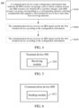
- FIG. 3 is a flow chart of an implementation of another antenna switching method according to an embodiment of the present disclosure, including the following act S310.
- a communication device sends configuration information; the configuration information indicates M Sounding Reference Signal (SRS) resource set groups, each of which contains at least one SRS resource set; wherein M is a positive integer; each SRS resource set group corresponds to a corresponding antenna switching configuration that supports a first terminal device to have more than four receiving antennas.
- SRS Sounding Reference Signal
- the antenna switching configuration is represented by xTyR; wherein y is an integer greater than 4 and x is a positive integer; xTyR indicates that the SRS supports transmission by x antenna ports, y corresponds to the number of all or part of receiving antennas of the first terminal device.
- the communication device is a network device or a second terminal device.
- the communication device sends the configuration information to the first terminal device.
- the communication device receives an antenna switching capability reported by the first terminal device, and the antenna switching capability supports the antenna switching configuration represented by the xTyR.
- the communication device receives the antenna switching capability reported by the first terminal through an RRC signaling.
- FIG. 4 is a flow chart of an implementation of another antenna switching method according to an embodiment of the present disclosure. As shown in FIG. 4 , the act S310 may be followed by acts S420 and S430.
- the communication device receives an SRS signal sent by the first terminal device according to the configuration information.
- a pre-coding matrix or a beamforming matrix of the first terminal device is determined according to the SRS signal.
- FIG. 5 is a schematic diagram of a structure of a terminal device 500 according to an embodiment of the present disclosure.
- the terminal device 500 includes: a receiving module 510, which is configured to receive configuration information; wherein the configuration information indicates M Sounding Reference Signal (SRS) resource set groups, each of which contains at least one SRS resource set; wherein M is a positive integer; each SRS resource set group corresponds to a corresponding antenna switching configuration that supports a first terminal device to have more than four receiving antennas.
- SRS Sounding Reference Signal
- the antenna switching configuration is represented by xTyR; wherein y is an integer greater than 4 and x is a positive integer; xTyR indicates that the SRS supports transmission by x antenna ports, y corresponds to the number of all or part of receiving antennas of the first terminal device.
- FIG. 6 is a schematic diagram of a structure of a communication device 600 according to an embodiment of the present disclosure.
- the communication device 600 includes: a sending module 611, which is configured to send configuration information; wherein the configuration information indicates M Sounding Reference Signal (SRS) resource set groups, each of which contains at least one SRS resource set; wherein M is a positive integer; each SRS resource set group corresponds to a corresponding antenna switching configuration that supports a first terminal device to have more than four receiving antennas.
- SRS Sounding Reference Signal
- the antenna switching configuration is represented by xTyR; wherein y is an integer greater than 4 and x is a positive integer; xTyR indicates that the SRS supports transmission by x antenna ports, y corresponds to the number of all or part of receiving antennas of the first terminal device.
- the communication device may be a network device or a terminal device.
- FIG. 7 is a schematic diagram of a structure of a communication device 700 according to an embodiment of the present disclosure.
- the communication device 700 shown in FIG. 7 includes a processor 610, which may invoke and run a computer program from a memory to implement any of the methods in the embodiments of the present disclosure.
- the communication device 700 may further include a memory 620.
- the processor 610 may invoke and run a computer program from the memory 620 to implement any of the methods in the embodiments of the present disclosure.
- the memory 620 may be a separate device independent of the processor 610, or may be integrated in the processor 610.
- the communication device 700 may further include a transceiver 630, and the processor 610 may control the transceiver 630 to communicate with another device.
- the transceiver 630 may send information or data to another device or receive information or data sent by another device.
- the transceiver 630 may include a transmitter and a receiver.
- the transceiver 630 may further include antennas, a quantity of which may be one or more.
- the communication device 700 may be the first terminal device according to the embodiments of the present disclosure, and the communication device 700 may implement corresponding flows implemented by the first terminal device in various methods of the embodiments of the present disclosure, which will not be repeated here for brevity.
- the communication device 700 may be a communication device according to the embodiments of the present disclosure (such as the network device or the second terminal device), and the communication device 700 may implement corresponding flows implemented by the communication device in various methods according to the embodiments of the present disclosure, which will not be repeated here for brevity.
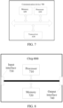
- FIG. 8 is a schematic diagram of a structure of a chip 800 according to an embodiment of the present disclosure.
- the chip 800 shown in FIG. 8 includes a processor 710, wherein the processor 710 may invoke and run a computer program from a memory to implement any of the methods in the embodiments of the present disclosure.
- the chip 800 may further include a memory 720.
- the processor 710 may invoke and run a computer program from the memory 720 to implement any of the methods in the embodiments of the present disclosure.
- the memory 720 may be a separate device independent of the processor 710, or may be integrated in the processor 710.
- the chip 700 may further include an input interface 730.
- the processor 710 may control the input interface 730 to communicate with another device or chip. Specifically, the processor 710 may acquire information or data sent by another device or chip.
- the chip 700 may further include an output interface 740.
- the processor 710 may control the output interface 740 to communicate with another device or chip. Specifically, the processor 710 may output information or data to another device or chip.
- the chip may be applied to the first terminal device in the embodiments of the present disclosure, and the chip may implement the corresponding flows implemented by the first terminal device in various methods of the embodiments of the present disclosure, which will not be repeated here for brevity.
- the chip may be applied to a communication device in the embodiment of the present disclosure, such as the network device or the second terminal device, and the chip may implement corresponding flows implemented by the communication device in various methods according to the embodiments of the present disclosure, which will not be repeated here for brevity.
- chip mentioned in the embodiments of the present disclosure may also be referred to as a system-level chip, a system chip, a chip system, or a system on chip, etc.
- the above-mentioned processor may be a general purpose processor, a Digital Signal Processor (DSP), a Field Programmable Gate Array (FPGA), an Application Specific Integrated Circuit (ASIC) or another programmable logic device, a transistor logic device, or a discrete hardware component, etc.
- DSP Digital Signal Processor
- FPGA Field Programmable Gate Array
- ASIC Application Specific Integrated Circuit
- the above-mentioned general-purpose processor may be a microprocessor or any conventional processor, etc.
- the above-mentioned memory may be a volatile memory or non-volatile memory, or may include both volatile and non-volatile memories.
- the non-volatile memory may be a Read-Only Memory (ROM), a Programmable ROM (PROM), an Erasable PROM (EPROM), an Electrically EPROM (EEPROM), or a flash memory.
- the volatile memory may be a Random Access Memory (RAM).
- the memory in the embodiment of the present disclosure may be a Static RAM (SRAM), a Dynamic RAM (DRAM), a Synchronous DRAM (SDRAM), a Double Data Rate SDRAM (DDR SDRAM), an Enhanced SDRAM (ESDRAM), a Synch Link DRAM (SLDRAM), and a Direct Rambus RAM (DR RAM), etc.
- SRAM Static RAM
- DRAM Dynamic RAM
- SDRAM Synchronous DRAM
- DDR SDRAM Double Data Rate SDRAM
- ESDRAM Enhanced SDRAM
- SLDRAM Synch Link DRAM
- DR RAM Direct Rambus RAM
- the above-mentioned embodiments may be implemented in whole or in part through software, hardware, firmware, or any combination thereof.
- When implemented through software they may be implemented in whole or in part in a form of a computer program product.
- the computer program product includes one or more computer instructions.
- the computer program instructions When the computer program instructions are loaded and executed on a computer, flows or functions described in the embodiments of the present disclosure are generated in whole or in part.
- the computer may be a general purpose computer, a special purpose computer, a computer network, or another programmable apparatus.
- the computer instructions may be stored in a computer-readable storage medium, or transmitted from one computer-readable storage medium to another computer-readable storage medium, for example, the computer instructions may be transmitted from a website site, a computer, a server, or a data center to another website site, computer, server, or data center through a wired mode (e.g., a coaxial cable, an optical fiber, and a Digital Subscriber Line (DSL)) or a wireless mode (e.g., infrared radiation, radio, and microwave).
- the computer-readable storage medium may be any available medium that can be accessed by a computer or a data storage device such as a server, a data center, or the like that integrates one or more available media.
- the available media may be magnetic media (e.g., floppy disks, hard disks, magnetic tapes), optical media (e.g., Digital Versatile Disks (DVDs)), or semiconductor media (e.g., Solid State Disks (SSDs)), or the like.
- magnetic media e.g., floppy disks, hard disks, magnetic tapes
- optical media e.g., Digital Versatile Disks (DVDs)
- DVDs Digital Versatile Disks
- semiconductor media e.g., Solid State Disks (SSDs)
- sequence numbers of the various processes do not imply an order of execution of the various processes, which should be determined by their functions and internal logics, but should not constitute any limitation on implementation processes of the embodiments of the present disclosure.
Landscapes
- Engineering & Computer Science (AREA)
- Signal Processing (AREA)
- Computer Networks & Wireless Communication (AREA)
- Mobile Radio Communication Systems (AREA)
Claims (19)
- Procédé (200) de commutation d'antenne mis en œuvre par un premier dispositif terminal configuré pour être utilisable dans un système de communication radio selon la norme 3GPP, le procédé comprenant les étapes suivantes :recevoir (S210) des informations de configuration envoyées par un dispositif de réseau ;où les informations de configuration indiquent M groupes d'ensembles de ressources de signal de référence de sondage, SRS, chacun d'eux contenant au moins un ensemble de ressources SRS ; où M est un nombre entier positif ; où :chacun des groupes d'ensembles de ressources SRS correspond à une configuration de commutation d'antenne qui permet au premier dispositif terminal d'avoir plus de quatre antennes de réception ;où la configuration de commutation d'antenne est représentée par xTyR ; où y est un nombre entier supérieur à 4, et x est un nombre entier positif ; xTyR indique qu'un SRS prend en charge la transmission par x ports d'antenne, et y correspond à au nombre de la totalité ou d'une partie des antennes de réception du premier dispositif terminal ;où le procédé de commutation d'antenne comprend en outre : le signalement d'une première capacité de commutation d'antenne qui prend en charge la configuration de commutation d'antenne représentée par xTyR ;où le procédé de commutation d'antenne comprend en outre : lorsqu'une pluralité de ressources SRS dans un ensemble de ressources SRS sont transmises sur un même créneau, la non-transmission, par le premier dispositif terminal, d'autres signaux sur Y symboles d'une période de garde entre des ressources SRS adjacentes, où Y est un nombre entier positif ;la valeur de Y étant déterminée en fonction de l'espacement des sous-porteuses ;lorsque la valeur de Y est supérieure à une valeur seuil prédéterminée ou égale à une valeur prédéterminée, une période de garde entre des ressources SRS dans différents ensembles de ressources SRS dans un même groupe d'ensembles de ressources SRS est supérieure ou égale à Y symboles ;où une valeur configurable d'un champ resourceType correspondant à un ensemble de ressources SRS est apériodique, semi-persistante ou périodique ; et M est égal à 1, 2 ou 3,le procédé comprenant de transmettre un signal SRS conformément aux informations de configuration.
- Procédé selon la revendication 1, dans lequel, si un champ resourceType correspondant à un ensemble de ressources SRS contenu dans un groupe d'ensembles de ressources SRS est configuré pour être périodique ou semi-persistant, le groupe d'ensembles de ressources SRS contient un ensemble de ressources SRS.
- Procédé selon la revendication 1, dans lequel : lorsque x n'est pas égal à y, les champs resourceType correspondant aux ensembles de ressources SRS dans différents groupes d'ensembles de ressources SRS sont configurés pour prendre des valeurs différentes.
- Procédé selon l'une quelconque des revendications 1 à 3, dans lequel :les M groupes d'ensembles de ressources SRS contiennent au moins un deuxième groupe d'ensembles de ressources SRS, et un deuxième groupe d'ensembles de ressources SRS correspond à une configuration de commutation d'antenne correspondant à 4T8R ;le deuxième groupe d'ensembles de ressources SRS contient un ensemble de ressources SRS, chaque ensemble de ressources SRS contient deux ressources SRS et chaque ressource SRS est configurée avec quatre ports SRS.
- Procédé selon l'une quelconque des revendications 1 à 3, dans lequel :les M groupes d'ensembles de ressources SRS contiennent au moins un troisième groupe d'ensembles de ressources SRS, et un troisième groupe d'ensembles de ressources SRS correspond à une configuration de commutation d'antenne correspondant à 2T8R ;si un champ resourceType correspondant à un ensemble de ressources SRS dans le troisième groupe d'ensembles de ressources SRS est configuré pour être périodique ou semi-persistant, le troisième groupe d'ensembles de ressources SRS contient un ensemble de ressources SRS, et l'ensemble de ressources SRS contient quatre ressources SRS, et chaque ressource SRS est configurée avec deux ports SRS.
- Procédé selon l'une quelconque des revendications 1 à 3, dans lequel :les M groupes d'ensembles de ressources SRS contiennent au moins un quatrième groupe d'ensembles de ressources SRS, et un quatrième groupe d'ensembles de ressources SRS correspond à une configuration de commutation d'antenne correspondant à 2T8R ;si un champ resourceType correspondant à un ensemble de ressources SRS dans le quatrième groupe d'ensembles de ressources SRS est configuré pour être apériodique, le quatrième groupe d'ensembles de ressources SRS contient deux ensembles de ressources SRS, chaque ensemble de ressources SRS contient deux ressources SRS, et chaque ressource SRS est configurée avec deux ports SRS ; les ressources SRS dans différents ensembles de ressources SRS sont transmises sur des créneaux différents, et les ressources SRS dans un même ensemble de ressources sont transmises sur différents symboles d'un même créneau ; oule quatrième groupe d'ensembles de ressources SRS contient deux ensembles de ressources SRS, l'un des deux ensembles de ressources SRS contient une ressource SRS et l'autre ensemble de ressources SRS contient trois ressources SRS ; chaque ressource SRS est configurée avec deux ports SRS ; les ressources SRS dans différents ensembles de ressources SRS sont transmises sur des créneaux différents, et les ressources SRS dans un même ensemble de ressources sont transmises sur des symboles différents d'un même créneau ; oule quatrième groupe d'ensembles de ressources SRS contient un ensemble de ressources SRS, l'ensemble de ressources SRS contient quatre ressources SRS, et chaque ressource SRS est configurée avec deux ports SRS.
- Procédé selon l'une quelconque des revendications 1 à 3, dans lequel :les M groupes d'ensembles de ressources SRS contiennent au moins un cinquième groupe d'ensembles de ressources SRS, et un cinquième groupe d'ensembles de ressources SRS correspond à une configuration de commutation d'antenne correspondant à 1T8R ;si un champ resourceType correspondant à un ensemble de ressources SRS dans le cinquième groupe d'ensembles de ressources SRS est configuré pour être périodique ou semi-persistant, le cinquième groupe d'ensembles de ressources SRS contient un ensemble de ressources SRS, et l'ensemble de ressources SRS contient huit ressources SRS, et chaque ressource SRS est configurée avec un port SRS.
- Procédé selon l'une quelconque des revendications 1 à 3, dans lequel :les M groupes d'ensembles de ressources SRS contiennent au moins un sixième groupe d'ensembles de ressources SRS, et un sixième groupe d'ensembles de ressources SRS correspond à une configuration de commutation d'antenne correspondant à 1T8R ;si un champ resourceType correspondant à un ensemble de ressources SRS dans le sixième groupe d'ensembles de ressources SRS est configuré pour être apériodique, le sixième groupe d'ensembles de ressources SRS contient deux ensembles de ressources SRS, les deux ensembles de ressources SRS sont configurés avec huit ressources SRS au total, chaque ressource SRS est configurée avec un port SRS ; les ressources SRS dans les différents ensembles de ressources SRS sont transmises sur des créneaux différents, et les ressources SRS dans un même ensemble de ressources sont transmises sur des symboles différents d'un même créneau ; oule sixième groupe d'ensembles de ressources SRS contient trois ensembles de ressources SRS, les trois ensembles de ressources SRS contiennent huit ressources SRS au total, et chaque ressource SRS contient un port SRS ; les ressources SRS dans les différents ensembles de ressources SRS sont transmises sur des créneaux différents, et les ressources SRS dans un même ensemble de ressources sont transmises sur des symboles différents d'un même créneau ; oule sixième groupe d'ensembles de ressources SRS contient quatre ensembles de ressources SRS, les quatre ensembles de ressources SRS contiennent huit ressources SRS au total, et chaque ressource SRS est configurée avec un port SRS ; les ressources SRS dans les différents ensembles de ressources SRS sont transmises sur des créneaux différents, et les ressources SRS dans un même ensemble de ressources sont transmises sur des symboles différents d'un même créneau.
- Procédé selon l'une quelconque des revendications 1 à 3, dans lequel :les M groupes d'ensembles de ressources SRS contiennent au moins un huitième groupe d'ensembles de ressources SRS, et un huitième groupe d'ensembles de ressources SRS correspond à une configuration de commutation d'antenne correspondant à 2T6R ;si un champ resourceType correspondant à un ensemble de ressources SRS dans le huitième groupe d'ensembles de ressources SRS est configuré pour être périodique ou semi-persistant, le huitième groupe d'ensembles de ressources SRS contient un ensemble de ressources SRS, et l'ensemble de ressources SRS contient trois ressources SRS, et chaque ressource SRS est configurée avec deux ports SRS.
- Procédé selon l'une quelconque des revendications 1 à 3, dans lequel :les M groupes d'ensembles de ressources SRS contiennent au moins un neuvième groupe d'ensembles de ressources SRS, et un neuvième groupe d'ensembles de ressources SRS correspond à une configuration de commutation d'antenne correspondant à 2T6R ;si un champ resourceType correspondant à un ensemble de ressources SRS dans le neuvième groupe d'ensembles de ressources SRS est configuré pour être apériodique, le neuvième groupe d'ensembles de ressources SRS contient un ensemble de ressources SRS, et l'ensemble de ressources SRS contient trois ressources SRS, et chaque ressource SRS est configurée avec deux ports SRS ; oule neuvième groupe d'ensembles de ressources SRS contient deux ensembles de ressources SRS, l'un des deux ensembles de ressources SRS contient une ressource SRS et l'autre ensemble de ressources SRS contient deux ressources SRS, chaque ressource SRS est configurée avec deux ports SRS ; les ressources SRS dans des ensembles différents de ressources SRS sont transmises sur des créneaux différents, et les ressources SRS dans un même ensemble de ressources sont transmises sur des symboles différents d'un même créneau.
- Procédé selon l'une quelconque des revendications 1 à 3, dans lequel :les M groupes d'ensembles de ressources SRS contiennent au moins un dixième groupe d'ensembles de ressources SRS, et un dixième groupe d'ensembles de ressources SRS correspond à une configuration de commutation d'antenne correspondant à 1T6R ;si un champ resourceType correspondant à un ensemble de ressources SRS dans le dixième groupe d'ensembles de ressources SRS est configuré pour être périodique ou semi-persistant, le dixième groupe d'ensembles de ressources SRS contient un ensemble de ressources SRS, et l'ensemble de ressources SRS contient six ressources SRS, et chaque ressource SRS est configurée avec un port SRS.
- Procédé selon l'une quelconque des revendications 1 à 3, dans lequel :les M groupes d'ensembles de ressources SRS contiennent au moins un onzième groupe d'ensembles de ressources SRS, et un onzième groupe d'ensembles de ressources SRS correspond à une configuration de commutation d'antenne correspondant à 1T6R ;si un champ resourceType correspondant à un ensemble de ressources SRS dans le onzième groupe d'ensembles de ressources SRS est configuré pour être apériodique, le onzième groupe d'ensembles de ressources SRS contient deux ensembles de ressources SRS, les deux ensembles de ressources SRS contiennent six ressources SRS au total, chaque ressource SRS est configurée avec un port SRS ; les ressources SRS dans des ensembles de ressources SRS différents sont transmises sur des créneaux différents, et les ressources SRS dans un même ensemble de ressources sont transmises sur des symboles différents d'un même créneau ; oule onzième groupe d'ensembles de ressources SRS contient trois ensembles de ressources SRS, les trois ensembles de ressources SRS contiennent six ressources SRS au total, et chaque ressource SRS est configurée avec un port SRS ; les ressources SRS dans des ensembles de ressources SRS différents sont transmises sur différents créneaux, et les ressources SRS dans le même ensemble de ressources sont transmises sur des symboles différents d'un même créneau ; oule onzième groupe d'ensembles de ressources SRS contient un ensemble de ressources SRS qui contient six ressources SRS, et chaque ressource SRS est configurée avec un port SRS.
- Dispositif terminal (500) configuré pour fonctionner dans un système de communication radio selon la norme 3GPP, le dispositif terminal comprenant :un module de réception (510), configuré pour recevoir des informations de configuration envoyées par un dispositif de réseau ; où les informations de configuration indiquent M groupes d'ensembles de ressources de signal de référence de sondage, SRS, chacun d'eux contenant au moins un ensemble de ressources SRS ; où M est un nombre entier positif ;où :chacun des groupes d'ensembles de ressources SRS correspond à une configuration de commutation d'antenne qui permet à l'appareil terminal d'avoir plus de quatre antennes de réception ;où la configuration de commutation d'antenne est représentée par xTyR ; où y est un nombre entier supérieur à 4, et x est un nombre entier positif ; xTyR indique que le SRS prend en charge la transmission par x ports d'antenne, y correspond au nombre de la totalité ou d'une partie des antennes de réception du dispositif terminal ;où le dispositif terminal signale une première capacité de commutation d'antenne qui prend en charge la configuration de commutation d'antenne représentée par xTyR ;où, lorsqu'une pluralité de ressources SRS dans un ensemble de ressources SRS sont transmises sur un même créneau, le dispositif terminal ne transmet pas d'autres signaux sur Y symboles d'une période de garde entre des ressources SRS adjacentes, où Y est un nombre entier positif ;une valeur de Y étant déterminée en fonction de l'espacement des sous-porteuses ;lorsque la valeur de Y est supérieure à une valeur seuil prédéterminée ou égale à une valeur prédéterminée, une période de garde entre des ressources SRS dans différents ensembles de ressources SRS dans un même groupe d'ensembles de ressources SRS est supérieure ou égale à Y symboles ;où une valeur configurable d'un champ resourceType correspondant à un ensemble de ressources SRS est apériodique, semi-persistante ou périodique ; et M est égal à 1, 2 ou 3,où le dispositif terminal transmet un signal SRS conformément aux informations de configuration.
- Dispositif terminal selon la revendication 13, dans lequel une ressource SRS contenue dans l'ensemble de ressources SRS occupe la totalité ou une partie des symboles d'un créneau ; etla ressource SRS contenue dans l'ensemble de ressources SRS occupe au moins un symbole des six derniers symboles d'un créneau ; oule symbole occupé par la ressource SRS est déterminé en fonction d'une deuxième capacité signalée par le dispositif terminal ;
etlorsque le dispositif terminal ne signale pas la deuxième capacité, la ressource SRS contenue dans l'ensemble de ressources SRS occupe au moins un symbole des six derniers symboles d'un emplacement ;
oula deuxième capacité est utilisée pour indiquer les informations de symboles disponibles qui sont disponibles pour la configuration des ressources SRS par le dispositif terminal dans un créneau. - Dispositif terminal selon la revendication 13 ou la revendication 14, dans lequel, si la commutation d'antenne correspondant à xTyR est configurée pour l'au moins un ensemble de ressources SRS, où y est égal à 6 ou 8, différents ensembles de ressources SRS sont transmis sur différents créneaux lorsque x est inférieur à y.
- Dispositif terminal selon l'une quelconque des revendications 13 à 15, dans lequel les ports SRS pour une ressource SRS dans un groupe d'ensembles de ressources SRS correspondent à différents ports d'antenne du dispositif terminal.
- Dispositif terminal selon l'une quelconque des revendications 13 à 16, dans lequel les informations de configuration correspondent à une troisième capacité signalée par le dispositif terminal ;où la troisième capacité indique que le dispositif terminal a une capacité de commutation d'antenne correspondant à xTyR ;où il y a au moins un y, qui prend l'une des valeurs 6 et 8, dans le xTyR correspondant à la capacité de commutation d'antenne, ou il y a au moins un y, qui prend la valeur 8, dans le xTyR correspondant à la capacité de commutation d'antenne.
- Dispositif terminal selon l'une quelconque des revendications 13 à 17, dans lequel un champ d'utilisation dans un élément d'informations, IE, de contrôle des ressources radio, RRC, correspondant à l'ensemble de ressources SRS est configuré pour être AntennaSwitching ; ou
un champ resourceType correspondant à au moins un ensemble de ressources SRS dans un groupe d'ensembles de ressources SRS est configuré pour avoir la même valeur. - Dispositif terminal selon l'une quelconque des revendications 13 à 17, dans lequel un espacement entre sous-porteuses correspondant à une ressource SRS dans l'ensemble de ressources SRS est un espacement parmi les suivants : 15 kHz, 30 kHz, 60 kHz et 120 kHz ; oul'un parmi 15 kHz, 30 kHz, 60 kHz, 120 kHz et 240 kHz ; oul'un parmi 15 kHz, 30 kHz, 60 kHz, 120 kHz, 240 kHz et 480 kHz ; oul'un parmi 15 kHz, 30 kHz, 60 kHz, 120 kHz, 240 kHz, 480 kHz et 960 kHz ; oul'un parmi 15 kHz, 30 kHz, 60 kHz, 120 kHz, 240 kHz, 480 kHz, 960 kHz et 1920 kHz.
Priority Applications (1)
| Application Number | Priority Date | Filing Date | Title |
|---|---|---|---|
| EP24157400.3A EP4344084B1 (fr) | 2020-02-19 | 2020-02-19 | Procédé de commutation d'antenne, dispositif terminal et dispositif de communication |
Applications Claiming Priority (1)
| Application Number | Priority Date | Filing Date | Title |
|---|---|---|---|
| PCT/CN2020/075905 WO2021163938A1 (fr) | 2020-02-19 | 2020-02-19 | Procédé de commutation d'antenne, dispositif terminal, et dispositif de communication |
Related Child Applications (2)
| Application Number | Title | Priority Date | Filing Date |
|---|---|---|---|
| EP24157400.3A Division EP4344084B1 (fr) | 2020-02-19 | 2020-02-19 | Procédé de commutation d'antenne, dispositif terminal et dispositif de communication |
| EP24157400.3A Division-Into EP4344084B1 (fr) | 2020-02-19 | 2020-02-19 | Procédé de commutation d'antenne, dispositif terminal et dispositif de communication |
Publications (3)
| Publication Number | Publication Date |
|---|---|
| EP4084385A1 EP4084385A1 (fr) | 2022-11-02 |
| EP4084385A4 EP4084385A4 (fr) | 2023-01-25 |
| EP4084385B1 true EP4084385B1 (fr) | 2024-04-24 |
Family
ID=77390352
Family Applications (2)
| Application Number | Title | Priority Date | Filing Date |
|---|---|---|---|
| EP24157400.3A Active EP4344084B1 (fr) | 2020-02-19 | 2020-02-19 | Procédé de commutation d'antenne, dispositif terminal et dispositif de communication |
| EP20920574.9A Active EP4084385B1 (fr) | 2020-02-19 | 2020-02-19 | Procédé de commutation d'antenne, dispositif terminal, et dispositif de communication |
Family Applications Before (1)
| Application Number | Title | Priority Date | Filing Date |
|---|---|---|---|
| EP24157400.3A Active EP4344084B1 (fr) | 2020-02-19 | 2020-02-19 | Procédé de commutation d'antenne, dispositif terminal et dispositif de communication |
Country Status (4)
| Country | Link |
|---|---|
| US (2) | US12519535B2 (fr) |
| EP (2) | EP4344084B1 (fr) |
| CN (1) | CN115023917A (fr) |
| WO (1) | WO2021163938A1 (fr) |
Families Citing this family (12)
| Publication number | Priority date | Publication date | Assignee | Title |
|---|---|---|---|---|
| KR20210132441A (ko) * | 2020-04-27 | 2021-11-04 | 삼성전자주식회사 | 무선 통신 시스템에서 사운딩 방법 및 장치 |
| US20230336304A1 (en) * | 2020-05-15 | 2023-10-19 | Nec Corporation | Method, device and computer readable medium for communication |
| US12507081B2 (en) * | 2020-08-03 | 2025-12-23 | Beijing Xiaomi Mobile Software Co., Ltd. | Method for signal transmission on reference signal resources and terminal |
| KR20230155477A (ko) * | 2021-03-16 | 2023-11-10 | 인텔 코포레이션 | 안테나 스위칭 및 캐리어 스위칭을 위한 사운딩 레퍼런스 신호 구성 |
| WO2023039769A1 (fr) * | 2021-09-15 | 2023-03-23 | 北京小米移动软件有限公司 | Procédé de déclenchement de signal de référence de sondage (srs) pour commutation d'antenne, et appareil associé |
| EP4404655A4 (fr) * | 2021-09-17 | 2025-07-02 | Beijing Xiaomi Mobile Software Co Ltd | Procédé et appareil pour rapporter la capacité de commutation d'antenne d'un dispositif terminal |
| CN116158041B (zh) * | 2021-09-23 | 2025-10-10 | 北京小米移动软件有限公司 | 一种用于天线切换配置的srs发送方法、装置及存储介质 |
| CN117730597A (zh) * | 2022-03-07 | 2024-03-19 | 北京小米移动软件有限公司 | 确定探测参考信号srs资源配置信息的方法及其装置 |
| WO2023198274A1 (fr) * | 2022-04-12 | 2023-10-19 | Nokia Technologies Oy | Configuration de ressources de signal de référence de liaison montante |
| CN117641395A (zh) * | 2022-08-31 | 2024-03-01 | 华为技术有限公司 | Srs的传输方法和装置 |
| CN118282593A (zh) * | 2022-12-30 | 2024-07-02 | 华为技术有限公司 | 传输参考信号的方法及通信装置 |
| CN117999808A (zh) * | 2023-12-29 | 2024-05-07 | 北京小米移动软件有限公司 | 用于3个发送天线的终端的通信方法、设备及存储介质 |
Family Cites Families (21)
| Publication number | Priority date | Publication date | Assignee | Title |
|---|---|---|---|---|
| WO2018126474A1 (fr) * | 2017-01-09 | 2018-07-12 | Qualcomm Incorporated | Transmission de ports de signaux de référence de sondage multiplexés dans une nouvelle radio |
| CN108111282B (zh) * | 2017-09-30 | 2020-11-24 | 中兴通讯股份有限公司 | 一种无线通信方法及装置 |
| CN109802801B (zh) * | 2017-11-17 | 2021-12-14 | 华为技术有限公司 | 发送和接收信号的方法、装置和系统 |
| KR102504455B1 (ko) * | 2018-01-12 | 2023-03-06 | 삼성전자 주식회사 | 무선 셀룰라 통신 시스템에서 비주기적 srs 전송 타이밍 결정 방법 및 장치 |
| CN110071749B (zh) * | 2018-01-22 | 2021-08-31 | 华为技术有限公司 | 一种天线选择指示方法、装置和系统 |
| US10938529B2 (en) * | 2018-02-14 | 2021-03-02 | Qualcomm Incorporated | Sounding reference signal antenna switching in scheduled entities having at least four antennas |
| CN108260217B (zh) * | 2018-03-05 | 2024-06-04 | 中兴通讯股份有限公司 | 一种信息传输的方法、装置和通信节点 |
| WO2019190236A1 (fr) * | 2018-03-29 | 2019-10-03 | 엘지전자 주식회사 | Procédé de transmission de signal de référence de sondage (srs) dans un système de communication sans fil et appareil associé |
| CN110474727B (zh) * | 2018-05-11 | 2021-04-13 | 中国移动通信有限公司研究院 | 基于上行信号的处理方法、装置、相关设备及存储介质 |
| CN110650485B (zh) * | 2018-06-26 | 2021-02-19 | 维沃移动通信有限公司 | 用于srs的天线切换传输方式指示方法、终端设备和网络设备 |
| CN111464275B (zh) * | 2019-01-21 | 2023-06-27 | 中国移动通信有限公司研究院 | 探测参考信号的发送配置、发送方法、终端及网络设备 |
| US11283651B2 (en) * | 2019-02-08 | 2022-03-22 | Qualcomm Incorporated | Sounding reference signal (SRS) resource and resource set configurations for positioning |
| WO2020168296A1 (fr) * | 2019-02-14 | 2020-08-20 | Hyoungsuk Jeon | Rapport de marge de puissance pour de multiples groupes d'antennes |
| CN111278130B (zh) * | 2019-04-30 | 2022-11-01 | 维沃移动通信有限公司 | Srs资源配置方法、bwp的切换处理方法和相关设备 |
| EP3998793A4 (fr) * | 2019-07-10 | 2023-03-29 | Ntt Docomo, Inc. | Terminal et procédé de communication sans fil |
| KR20220044585A (ko) * | 2019-08-16 | 2022-04-08 | 지티이 코포레이션 | Dl 및 ul 송신을 위한 패널-특정 보고의 방법 |
| US11638217B2 (en) * | 2019-10-09 | 2023-04-25 | Qualcomm Incorporated | SRS antenna switching for multiple receive antennas |
| CN111083773B (zh) * | 2019-10-12 | 2025-04-29 | 中兴通讯股份有限公司 | 功率控制的方法及装置、上行传输的发送方法及装置 |
| US20210135816A1 (en) * | 2019-12-13 | 2021-05-06 | Intel Corporation | Aperiodic sounding reference signal (srs) triggering and low overhead srs transmission with antenna switching |
| CN111262679A (zh) * | 2020-01-17 | 2020-06-09 | 展讯通信(上海)有限公司 | Srs资源的配置方法、系统、设备、介质及基站 |
| EP4104353A4 (fr) * | 2020-02-14 | 2023-11-01 | Lenovo (Beijing) Limited | Signaux de référence de sondage pour commutation d'antenne |
-
2020
- 2020-02-19 EP EP24157400.3A patent/EP4344084B1/fr active Active
- 2020-02-19 EP EP20920574.9A patent/EP4084385B1/fr active Active
- 2020-02-19 WO PCT/CN2020/075905 patent/WO2021163938A1/fr not_active Ceased
- 2020-02-19 CN CN202080094500.XA patent/CN115023917A/zh active Pending
-
2022
- 2022-07-28 US US17/815,759 patent/US12519535B2/en active Active
-
2025
- 2025-12-03 US US19/407,394 patent/US20260088887A1/en active Pending
Also Published As
| Publication number | Publication date |
|---|---|
| EP4084385A1 (fr) | 2022-11-02 |
| EP4084385A4 (fr) | 2023-01-25 |
| EP4344084A2 (fr) | 2024-03-27 |
| US20260088887A1 (en) | 2026-03-26 |
| WO2021163938A1 (fr) | 2021-08-26 |
| US20220368405A1 (en) | 2022-11-17 |
| EP4344084B1 (fr) | 2025-06-04 |
| CN115023917A (zh) | 2022-09-06 |
| US12519535B2 (en) | 2026-01-06 |
| EP4344084A3 (fr) | 2024-06-12 |
Similar Documents
| Publication | Publication Date | Title |
|---|---|---|
| EP4084385B1 (fr) | Procédé de commutation d'antenne, dispositif terminal, et dispositif de communication | |
| US12507158B2 (en) | Method for indicating antenna switching capability, terminal device and communication device | |
| US11937254B2 (en) | Wireless communcation method, terminal device, and network device | |
| US20230179374A1 (en) | Channel transmission method, terminal device, and network device | |
| EP3726767B1 (fr) | Procédé et dispositif de transmission de données et appareil de communication | |
| EP4075905B1 (fr) | Procédé de communication sans fil, équipement terminal et dispositif de réseau | |
| CN111106920B (zh) | 信息确定方法、终端设备和网络设备 | |
| CN113228781A (zh) | 无线通信方法、终端设备和网络设备 | |
| CN114631347A (zh) | 一种小区配置方法及装置、终端设备、网络设备 | |
| US20220338262A1 (en) | Information determination method, information indication method, terminal device, and network device | |
| CN116170117A (zh) | 侧行反馈信息处理方法、终端设备和网络设备 | |
| CN113507348A (zh) | 无线通信方法、终端设备和网络设备 | |
| EP4109938B1 (fr) | Procédé d'envoi de capacité de liaison latérale et dispositif terminal | |
| US20240007250A1 (en) | Wireless communication method, terminal device, and network device | |
| US20200374887A1 (en) | Channel transmission method and apparatus, and computer storage medium | |
| CN113597790A (zh) | 功率控制的方法、终端设备和网络设备 | |
| US20230129834A1 (en) | Method for determining antenna panel for transmission, and terminal device | |
| US20230344601A1 (en) | Wireless communication method, terminal device, and network device | |
| CN112771963A (zh) | 一种信息通知的方法和装置 |
Legal Events
| Date | Code | Title | Description |
|---|---|---|---|
| STAA | Information on the status of an ep patent application or granted ep patent |
Free format text: STATUS: THE INTERNATIONAL PUBLICATION HAS BEEN MADE |
|
| PUAI | Public reference made under article 153(3) epc to a published international application that has entered the european phase |
Free format text: ORIGINAL CODE: 0009012 |
|
| STAA | Information on the status of an ep patent application or granted ep patent |
Free format text: STATUS: REQUEST FOR EXAMINATION WAS MADE |
|
| 17P | Request for examination filed |
Effective date: 20220729 |
|
| AK | Designated contracting states |
Kind code of ref document: A1 Designated state(s): AL AT BE BG CH CY CZ DE DK EE ES FI FR GB GR HR HU IE IS IT LI LT LU LV MC MK MT NL NO PL PT RO RS SE SI SK SM TR |
|
| A4 | Supplementary search report drawn up and despatched |
Effective date: 20221222 |
|
| RIC1 | Information provided on ipc code assigned before grant |
Ipc: H04L 25/03 20060101ALN20221216BHEP Ipc: H04B 7/00 20060101ALI20221216BHEP Ipc: H04B 7/06 20060101ALI20221216BHEP Ipc: H04W 52/32 20090101ALI20221216BHEP Ipc: H04W 52/14 20090101ALI20221216BHEP Ipc: H04B 17/382 20150101ALI20221216BHEP Ipc: H04W 72/04 20090101ALI20221216BHEP Ipc: H04L 5/00 20060101AFI20221216BHEP |
|
| DAV | Request for validation of the european patent (deleted) | ||
| DAX | Request for extension of the european patent (deleted) | ||
| GRAJ | Information related to disapproval of communication of intention to grant by the applicant or resumption of examination proceedings by the epo deleted |
Free format text: ORIGINAL CODE: EPIDOSDIGR1 |
|
| GRAP | Despatch of communication of intention to grant a patent |
Free format text: ORIGINAL CODE: EPIDOSNIGR1 |
|
| RIC1 | Information provided on ipc code assigned before grant |
Ipc: H04L 25/03 20060101ALN20230929BHEP Ipc: H04B 7/08 20060101ALI20230929BHEP Ipc: H04B 7/00 20060101ALI20230929BHEP Ipc: H04B 7/06 20060101ALI20230929BHEP Ipc: H04W 52/32 20090101ALI20230929BHEP Ipc: H04W 52/14 20090101ALI20230929BHEP Ipc: H04B 17/382 20150101ALI20230929BHEP Ipc: H04W 72/04 20090101ALI20230929BHEP Ipc: H04L 5/00 20060101AFI20230929BHEP |
|
| GRAP | Despatch of communication of intention to grant a patent |
Free format text: ORIGINAL CODE: EPIDOSNIGR1 |
|
| STAA | Information on the status of an ep patent application or granted ep patent |
Free format text: STATUS: GRANT OF PATENT IS INTENDED |
|
| INTG | Intention to grant announced |
Effective date: 20231110 |
|
| RIC1 | Information provided on ipc code assigned before grant |
Ipc: H04L 25/03 20060101ALN20231027BHEP Ipc: H04B 7/08 20060101ALI20231027BHEP Ipc: H04B 7/00 20060101ALI20231027BHEP Ipc: H04B 7/06 20060101ALI20231027BHEP Ipc: H04W 52/32 20090101ALI20231027BHEP Ipc: H04W 52/14 20090101ALI20231027BHEP Ipc: H04B 17/382 20150101ALI20231027BHEP Ipc: H04W 72/04 20090101ALI20231027BHEP Ipc: H04L 5/00 20060101AFI20231027BHEP |
|
| INTC | Intention to grant announced (deleted) | ||
| RIC1 | Information provided on ipc code assigned before grant |
Ipc: H04L 25/03 20060101ALN20231103BHEP Ipc: H04B 7/08 20060101ALI20231103BHEP Ipc: H04B 7/00 20060101ALI20231103BHEP Ipc: H04B 7/06 20060101ALI20231103BHEP Ipc: H04W 52/32 20090101ALI20231103BHEP Ipc: H04W 52/14 20090101ALI20231103BHEP Ipc: H04B 17/382 20150101ALI20231103BHEP Ipc: H04W 72/04 20090101ALI20231103BHEP Ipc: H04L 5/00 20060101AFI20231103BHEP |
|
| INTG | Intention to grant announced |
Effective date: 20231120 |
|
| RIC1 | Information provided on ipc code assigned before grant |
Ipc: H04L 25/03 20060101ALN20231110BHEP Ipc: H04B 7/08 20060101ALI20231110BHEP Ipc: H04B 7/00 20060101ALI20231110BHEP Ipc: H04B 7/06 20060101ALI20231110BHEP Ipc: H04W 52/32 20090101ALI20231110BHEP Ipc: H04W 52/14 20090101ALI20231110BHEP Ipc: H04B 17/382 20150101ALI20231110BHEP Ipc: H04W 72/04 20090101ALI20231110BHEP Ipc: H04L 5/00 20060101AFI20231110BHEP |
|
| GRAS | Grant fee paid |
Free format text: ORIGINAL CODE: EPIDOSNIGR3 |
|
| GRAA | (expected) grant |
Free format text: ORIGINAL CODE: 0009210 |
|
| STAA | Information on the status of an ep patent application or granted ep patent |
Free format text: STATUS: THE PATENT HAS BEEN GRANTED |
|
| AK | Designated contracting states |
Kind code of ref document: B1 Designated state(s): AL AT BE BG CH CY CZ DE DK EE ES FI FR GB GR HR HU IE IS IT LI LT LU LV MC MK MT NL NO PL PT RO RS SE SI SK SM TR |
|
| REG | Reference to a national code |
Ref country code: GB Ref legal event code: FG4D |
|
| REG | Reference to a national code |
Ref country code: CH Ref legal event code: EP |
|
| REG | Reference to a national code |
Ref country code: DE Ref legal event code: R096 Ref document number: 602020029823 Country of ref document: DE |
|
| REG | Reference to a national code |
Ref country code: IE Ref legal event code: FG4D |
|
| P01 | Opt-out of the competence of the unified patent court (upc) registered |
Effective date: 20240521 |
|
| REG | Reference to a national code |
Ref country code: LT Ref legal event code: MG9D |
|
| REG | Reference to a national code |
Ref country code: NL Ref legal event code: MP Effective date: 20240424 |
|
| REG | Reference to a national code |
Ref country code: AT Ref legal event code: MK05 Ref document number: 1680774 Country of ref document: AT Kind code of ref document: T Effective date: 20240424 |
|
| PG25 | Lapsed in a contracting state [announced via postgrant information from national office to epo] |
Ref country code: NL Free format text: LAPSE BECAUSE OF FAILURE TO SUBMIT A TRANSLATION OF THE DESCRIPTION OR TO PAY THE FEE WITHIN THE PRESCRIBED TIME-LIMIT Effective date: 20240424 |
|
| PG25 | Lapsed in a contracting state [announced via postgrant information from national office to epo] |
Ref country code: NL Free format text: LAPSE BECAUSE OF FAILURE TO SUBMIT A TRANSLATION OF THE DESCRIPTION OR TO PAY THE FEE WITHIN THE PRESCRIBED TIME-LIMIT Effective date: 20240424 |
|
| PG25 | Lapsed in a contracting state [announced via postgrant information from national office to epo] |
Ref country code: IS Free format text: LAPSE BECAUSE OF FAILURE TO SUBMIT A TRANSLATION OF THE DESCRIPTION OR TO PAY THE FEE WITHIN THE PRESCRIBED TIME-LIMIT Effective date: 20240824 |
|
| PG25 | Lapsed in a contracting state [announced via postgrant information from national office to epo] |
Ref country code: BG Free format text: LAPSE BECAUSE OF FAILURE TO SUBMIT A TRANSLATION OF THE DESCRIPTION OR TO PAY THE FEE WITHIN THE PRESCRIBED TIME-LIMIT Effective date: 20240424 |
|
| PG25 | Lapsed in a contracting state [announced via postgrant information from national office to epo] |
Ref country code: HR Free format text: LAPSE BECAUSE OF FAILURE TO SUBMIT A TRANSLATION OF THE DESCRIPTION OR TO PAY THE FEE WITHIN THE PRESCRIBED TIME-LIMIT Effective date: 20240424 Ref country code: FI Free format text: LAPSE BECAUSE OF FAILURE TO SUBMIT A TRANSLATION OF THE DESCRIPTION OR TO PAY THE FEE WITHIN THE PRESCRIBED TIME-LIMIT Effective date: 20240424 |
|
| PG25 | Lapsed in a contracting state [announced via postgrant information from national office to epo] |
Ref country code: GR Free format text: LAPSE BECAUSE OF FAILURE TO SUBMIT A TRANSLATION OF THE DESCRIPTION OR TO PAY THE FEE WITHIN THE PRESCRIBED TIME-LIMIT Effective date: 20240725 |
|
| PG25 | Lapsed in a contracting state [announced via postgrant information from national office to epo] |
Ref country code: PT Free format text: LAPSE BECAUSE OF FAILURE TO SUBMIT A TRANSLATION OF THE DESCRIPTION OR TO PAY THE FEE WITHIN THE PRESCRIBED TIME-LIMIT Effective date: 20240826 |
|
| PG25 | Lapsed in a contracting state [announced via postgrant information from national office to epo] |
Ref country code: ES Free format text: LAPSE BECAUSE OF FAILURE TO SUBMIT A TRANSLATION OF THE DESCRIPTION OR TO PAY THE FEE WITHIN THE PRESCRIBED TIME-LIMIT Effective date: 20240424 |
|
| PG25 | Lapsed in a contracting state [announced via postgrant information from national office to epo] |
Ref country code: AT Free format text: LAPSE BECAUSE OF FAILURE TO SUBMIT A TRANSLATION OF THE DESCRIPTION OR TO PAY THE FEE WITHIN THE PRESCRIBED TIME-LIMIT Effective date: 20240424 |
|
| PG25 | Lapsed in a contracting state [announced via postgrant information from national office to epo] |
Ref country code: PL Free format text: LAPSE BECAUSE OF FAILURE TO SUBMIT A TRANSLATION OF THE DESCRIPTION OR TO PAY THE FEE WITHIN THE PRESCRIBED TIME-LIMIT Effective date: 20240424 |
|
| PG25 | Lapsed in a contracting state [announced via postgrant information from national office to epo] |
Ref country code: LV Free format text: LAPSE BECAUSE OF FAILURE TO SUBMIT A TRANSLATION OF THE DESCRIPTION OR TO PAY THE FEE WITHIN THE PRESCRIBED TIME-LIMIT Effective date: 20240424 |
|
| PG25 | Lapsed in a contracting state [announced via postgrant information from national office to epo] |
Ref country code: PT Free format text: LAPSE BECAUSE OF FAILURE TO SUBMIT A TRANSLATION OF THE DESCRIPTION OR TO PAY THE FEE WITHIN THE PRESCRIBED TIME-LIMIT Effective date: 20240826 Ref country code: PL Free format text: LAPSE BECAUSE OF FAILURE TO SUBMIT A TRANSLATION OF THE DESCRIPTION OR TO PAY THE FEE WITHIN THE PRESCRIBED TIME-LIMIT Effective date: 20240424 Ref country code: NO Free format text: LAPSE BECAUSE OF FAILURE TO SUBMIT A TRANSLATION OF THE DESCRIPTION OR TO PAY THE FEE WITHIN THE PRESCRIBED TIME-LIMIT Effective date: 20240724 Ref country code: LV Free format text: LAPSE BECAUSE OF FAILURE TO SUBMIT A TRANSLATION OF THE DESCRIPTION OR TO PAY THE FEE WITHIN THE PRESCRIBED TIME-LIMIT Effective date: 20240424 Ref country code: IS Free format text: LAPSE BECAUSE OF FAILURE TO SUBMIT A TRANSLATION OF THE DESCRIPTION OR TO PAY THE FEE WITHIN THE PRESCRIBED TIME-LIMIT Effective date: 20240824 Ref country code: HR Free format text: LAPSE BECAUSE OF FAILURE TO SUBMIT A TRANSLATION OF THE DESCRIPTION OR TO PAY THE FEE WITHIN THE PRESCRIBED TIME-LIMIT Effective date: 20240424 Ref country code: GR Free format text: LAPSE BECAUSE OF FAILURE TO SUBMIT A TRANSLATION OF THE DESCRIPTION OR TO PAY THE FEE WITHIN THE PRESCRIBED TIME-LIMIT Effective date: 20240725 Ref country code: FI Free format text: LAPSE BECAUSE OF FAILURE TO SUBMIT A TRANSLATION OF THE DESCRIPTION OR TO PAY THE FEE WITHIN THE PRESCRIBED TIME-LIMIT Effective date: 20240424 Ref country code: ES Free format text: LAPSE BECAUSE OF FAILURE TO SUBMIT A TRANSLATION OF THE DESCRIPTION OR TO PAY THE FEE WITHIN THE PRESCRIBED TIME-LIMIT Effective date: 20240424 Ref country code: BG Free format text: LAPSE BECAUSE OF FAILURE TO SUBMIT A TRANSLATION OF THE DESCRIPTION OR TO PAY THE FEE WITHIN THE PRESCRIBED TIME-LIMIT Effective date: 20240424 Ref country code: AT Free format text: LAPSE BECAUSE OF FAILURE TO SUBMIT A TRANSLATION OF THE DESCRIPTION OR TO PAY THE FEE WITHIN THE PRESCRIBED TIME-LIMIT Effective date: 20240424 Ref country code: RS Free format text: LAPSE BECAUSE OF FAILURE TO SUBMIT A TRANSLATION OF THE DESCRIPTION OR TO PAY THE FEE WITHIN THE PRESCRIBED TIME-LIMIT Effective date: 20240724 |
|
| PG25 | Lapsed in a contracting state [announced via postgrant information from national office to epo] |
Ref country code: DK Free format text: LAPSE BECAUSE OF FAILURE TO SUBMIT A TRANSLATION OF THE DESCRIPTION OR TO PAY THE FEE WITHIN THE PRESCRIBED TIME-LIMIT Effective date: 20240424 |
|
| PG25 | Lapsed in a contracting state [announced via postgrant information from national office to epo] |
Ref country code: EE Free format text: LAPSE BECAUSE OF FAILURE TO SUBMIT A TRANSLATION OF THE DESCRIPTION OR TO PAY THE FEE WITHIN THE PRESCRIBED TIME-LIMIT Effective date: 20240424 |
|
| PG25 | Lapsed in a contracting state [announced via postgrant information from national office to epo] |
Ref country code: CZ Free format text: LAPSE BECAUSE OF FAILURE TO SUBMIT A TRANSLATION OF THE DESCRIPTION OR TO PAY THE FEE WITHIN THE PRESCRIBED TIME-LIMIT Effective date: 20240424 |
|
| PG25 | Lapsed in a contracting state [announced via postgrant information from national office to epo] |
Ref country code: RO Free format text: LAPSE BECAUSE OF FAILURE TO SUBMIT A TRANSLATION OF THE DESCRIPTION OR TO PAY THE FEE WITHIN THE PRESCRIBED TIME-LIMIT Effective date: 20240424 Ref country code: SK Free format text: LAPSE BECAUSE OF FAILURE TO SUBMIT A TRANSLATION OF THE DESCRIPTION OR TO PAY THE FEE WITHIN THE PRESCRIBED TIME-LIMIT Effective date: 20240424 |
|
| REG | Reference to a national code |
Ref country code: DE Ref legal event code: R097 Ref document number: 602020029823 Country of ref document: DE |
|
| PG25 | Lapsed in a contracting state [announced via postgrant information from national office to epo] |
Ref country code: SM Free format text: LAPSE BECAUSE OF FAILURE TO SUBMIT A TRANSLATION OF THE DESCRIPTION OR TO PAY THE FEE WITHIN THE PRESCRIBED TIME-LIMIT Effective date: 20240424 |
|
| PG25 | Lapsed in a contracting state [announced via postgrant information from national office to epo] |
Ref country code: SM Free format text: LAPSE BECAUSE OF FAILURE TO SUBMIT A TRANSLATION OF THE DESCRIPTION OR TO PAY THE FEE WITHIN THE PRESCRIBED TIME-LIMIT Effective date: 20240424 Ref country code: SK Free format text: LAPSE BECAUSE OF FAILURE TO SUBMIT A TRANSLATION OF THE DESCRIPTION OR TO PAY THE FEE WITHIN THE PRESCRIBED TIME-LIMIT Effective date: 20240424 Ref country code: RO Free format text: LAPSE BECAUSE OF FAILURE TO SUBMIT A TRANSLATION OF THE DESCRIPTION OR TO PAY THE FEE WITHIN THE PRESCRIBED TIME-LIMIT Effective date: 20240424 Ref country code: EE Free format text: LAPSE BECAUSE OF FAILURE TO SUBMIT A TRANSLATION OF THE DESCRIPTION OR TO PAY THE FEE WITHIN THE PRESCRIBED TIME-LIMIT Effective date: 20240424 Ref country code: DK Free format text: LAPSE BECAUSE OF FAILURE TO SUBMIT A TRANSLATION OF THE DESCRIPTION OR TO PAY THE FEE WITHIN THE PRESCRIBED TIME-LIMIT Effective date: 20240424 Ref country code: CZ Free format text: LAPSE BECAUSE OF FAILURE TO SUBMIT A TRANSLATION OF THE DESCRIPTION OR TO PAY THE FEE WITHIN THE PRESCRIBED TIME-LIMIT Effective date: 20240424 |
|
| PLBE | No opposition filed within time limit |
Free format text: ORIGINAL CODE: 0009261 |
|
| STAA | Information on the status of an ep patent application or granted ep patent |
Free format text: STATUS: NO OPPOSITION FILED WITHIN TIME LIMIT |
|
| 26N | No opposition filed |
Effective date: 20250127 |
|
| PG25 | Lapsed in a contracting state [announced via postgrant information from national office to epo] |
Ref country code: SI Free format text: LAPSE BECAUSE OF FAILURE TO SUBMIT A TRANSLATION OF THE DESCRIPTION OR TO PAY THE FEE WITHIN THE PRESCRIBED TIME-LIMIT Effective date: 20240424 |
|
| PG25 | Lapsed in a contracting state [announced via postgrant information from national office to epo] |
Ref country code: SE Free format text: LAPSE BECAUSE OF FAILURE TO SUBMIT A TRANSLATION OF THE DESCRIPTION OR TO PAY THE FEE WITHIN THE PRESCRIBED TIME-LIMIT Effective date: 20240424 |
|
| PG25 | Lapsed in a contracting state [announced via postgrant information from national office to epo] |
Ref country code: MC Free format text: LAPSE BECAUSE OF FAILURE TO SUBMIT A TRANSLATION OF THE DESCRIPTION OR TO PAY THE FEE WITHIN THE PRESCRIBED TIME-LIMIT Effective date: 20240424 |
|
| REG | Reference to a national code |
Ref country code: CH Ref legal event code: PL |
|
| PG25 | Lapsed in a contracting state [announced via postgrant information from national office to epo] |
Ref country code: LU Free format text: LAPSE BECAUSE OF NON-PAYMENT OF DUE FEES Effective date: 20250219 |
|
| PG25 | Lapsed in a contracting state [announced via postgrant information from national office to epo] |
Ref country code: CH Free format text: LAPSE BECAUSE OF NON-PAYMENT OF DUE FEES Effective date: 20250228 |
|
| REG | Reference to a national code |
Ref country code: BE Ref legal event code: MM Effective date: 20250228 |
|
| PG25 | Lapsed in a contracting state [announced via postgrant information from national office to epo] |
Ref country code: BE Free format text: LAPSE BECAUSE OF NON-PAYMENT OF DUE FEES Effective date: 20250228 |
|
| PG25 | Lapsed in a contracting state [announced via postgrant information from national office to epo] |
Ref country code: IE Free format text: LAPSE BECAUSE OF NON-PAYMENT OF DUE FEES Effective date: 20250219 |
|
| PG25 | Lapsed in a contracting state [announced via postgrant information from national office to epo] |
Ref country code: IT Free format text: LAPSE BECAUSE OF FAILURE TO SUBMIT A TRANSLATION OF THE DESCRIPTION OR TO PAY THE FEE WITHIN THE PRESCRIBED TIME-LIMIT Effective date: 20240424 |
|
| PGFP | Annual fee paid to national office [announced via postgrant information from national office to epo] |
Ref country code: GB Payment date: 20260224 Year of fee payment: 7 |
|
| PGFP | Annual fee paid to national office [announced via postgrant information from national office to epo] |
Ref country code: DE Payment date: 20260223 Year of fee payment: 7 |
|
| PGFP | Annual fee paid to national office [announced via postgrant information from national office to epo] |
Ref country code: FR Payment date: 20260224 Year of fee payment: 7 |