EP4084642B1 - Handschuh mit integriertem spannungsdetektor - Google Patents
Handschuh mit integriertem spannungsdetektor Download PDFInfo
- Publication number
- EP4084642B1 EP4084642B1 EP20909372.3A EP20909372A EP4084642B1 EP 4084642 B1 EP4084642 B1 EP 4084642B1 EP 20909372 A EP20909372 A EP 20909372A EP 4084642 B1 EP4084642 B1 EP 4084642B1
- Authority
- EP
- European Patent Office
- Prior art keywords
- glove
- pass filter
- band pass
- inner layer
- outer layer
- Prior art date
- Legal status (The legal status is an assumption and is not a legal conclusion. Google has not performed a legal analysis and makes no representation as to the accuracy of the status listed.)
- Active
Links
Images

Classifications
-
- A—HUMAN NECESSITIES
- A41—WEARING APPAREL
- A41D—OUTERWEAR; PROTECTIVE GARMENTS; ACCESSORIES
- A41D19/00—Gloves
- A41D19/0024—Gloves with accessories
- A41D19/0027—Measuring instruments, e.g. watch, thermometer
-
- A—HUMAN NECESSITIES
- A41—WEARING APPAREL
- A41D—OUTERWEAR; PROTECTIVE GARMENTS; ACCESSORIES
- A41D19/00—Gloves
- A41D19/001—Linings
-
- A—HUMAN NECESSITIES
- A41—WEARING APPAREL
- A41D—OUTERWEAR; PROTECTIVE GARMENTS; ACCESSORIES
- A41D19/00—Gloves
- A41D19/015—Protective gloves
- A41D19/01594—Protective gloves with accessories, e.g. tools, receptacles
-
- A—HUMAN NECESSITIES
- A41—WEARING APPAREL
- A41D—OUTERWEAR; PROTECTIVE GARMENTS; ACCESSORIES
- A41D31/00—Materials specially adapted for outerwear
- A41D31/04—Materials specially adapted for outerwear characterised by special function or use
- A41D31/26—Electrically protective, e.g. preventing static electricity or electric shock
- A41D31/265—Electrically protective, e.g. preventing static electricity or electric shock using layered materials
-
- G—PHYSICS
- G01—MEASURING; TESTING
- G01R—MEASURING ELECTRIC VARIABLES; MEASURING MAGNETIC VARIABLES
- G01R19/00—Arrangements for measuring currents or voltages or for indicating presence or sign thereof
- G01R19/0046—Arrangements for measuring currents or voltages or for indicating presence or sign thereof characterised by a specific application or detail not covered by any other subgroup of G01R19/00
-
- G—PHYSICS
- G01—MEASURING; TESTING
- G01R—MEASURING ELECTRIC VARIABLES; MEASURING MAGNETIC VARIABLES
- G01R19/00—Arrangements for measuring currents or voltages or for indicating presence or sign thereof
- G01R19/0084—Measuring voltage only
-
- G—PHYSICS
- G01—MEASURING; TESTING
- G01R—MEASURING ELECTRIC VARIABLES; MEASURING MAGNETIC VARIABLES
- G01R19/00—Arrangements for measuring currents or voltages or for indicating presence or sign thereof
- G01R19/145—Indicating the presence of current or voltage
- G01R19/155—Indicating the presence of voltage
Definitions
- AC alternating current
- a power line may have been downed by a windstorm, and a first responder will have no idea whether or not the power line remains "live.”
- a plumber repairing a broken copper pipe may be unaware that elsewhere in the building an exposed wire has come into contact with a distant end of the same copper pipe. Every year, there are thousands of accidental electrocutions in occupational settings, making electrical injuries the fourth-leading cause of workplace-related traumatic death.
- non-contact AC voltage detectors which detect the changing electric and magnetic fields around an AC-carrying conductor.
- the technology behind non-contact AC voltage detection is well-understood and commercial hand-held detectors are readily available in the marketplace.
- commercially-available hand-held detectors are inconvenient in that they require the user to remove the detector from a toolbox or pocket, bring the detector probe(s) near the conductive material, and then return the detector to the toolbox or pocket. This inconvenience may transform into actual risk of accidental electrocution. For example, at the beginning of the job, an electrician may confirm, using a hand-held detector, that a circuit box is not energized.
- a better solution might be a non-contact AC voltage detector that is incorporated into something that the worker would be carrying or wearing as part of the course of performance of the work.
- One choice might be something that the worker may be wearing on the hand, such as a glove.
- a voltage detector that has been incorporated into a glove will be of value to a worker only if the glove itself is still useful for its primary purpose, namely use as an article of clothing that protects the hand and/or provides additional grip strength for picking up and holding articles.
- producing such a glove that is useful both as a glove and as a voltage detector has proven elusive.
- WO 2014158030 discloses an "electrical energy detection glove" that uses a wire loop antenna integrated into the back of the hand and/or fingers.
- a wire loop antenna has a number of drawbacks: it requires close (and potentially dangerous) proximity to detect nearby AC voltage, the detected signal will likely lose strength as it passes through the loop, and the disclosed design will have a single point of failure.
- D1 US 9 939 468 B1 , which discloses the preambles of the independent claims, discloses a "Wearable Non Contacting Voltage Detection System" which includes an antenna network located throughout anterior hand and distal ends of a glove.
- Embodiments of the inventive glove solve the problem of incorporating an AC voltage detector into an everyday work glove without adversely affecting the performance of the glove. More particularly, embodiments of the inventive glove use thin, lightweight monopole aerials extending into the top of each of the glove fingers. The aerials are separated from the user's fingers with a thin layer of dielectric material acting as an electrical barrier. This provides suitable sensitivity, from a safe distance, to any nearby AC voltage, it does not require the user to hold the glove at a particular angle to the conductive material, and the AC voltage detector will continue to function even if some of the aerials cease to function because of normal wear and tear or physical impact.
- embodiments of the inventive glove include AC voltage detection and alerting circuitry connected to the aerials.
- This circuity provides, at a minimum, the capability to detect the presence of AC voltage, eliminate background noise, and alert the user to the presence of dangerous AC voltage.
- the circuitry includes a ground connection in physical contact with the user's body, making the detection circuitry more sensitive to the presence of AC voltage. This increased sensitivity allows for the use of a thinner dielectric layer separating the aerials from the user's hand, which in turn avoids unnecessary stiffening of the glove and decreasing its usefulness as a glove.
- the detection circuitry may include a microcontroller or microprocessor, non-volatile memory, an accelerometer, a GPS receiver, a motion-powered charger, visual, audio, and/or haptic alert components, and wired or wireless communications interfaces.
- a microcontroller or microprocessor non-volatile memory
- an accelerometer e.g., a Bosch Sensortec BMA150 accelerometer
- GPS receiver e.g., a Bosch Sensor fidelity
- a motion-powered charger e.g., a GPS receiver
- visual, audio, and/or haptic alert components e.g., a wireless haptic alert components
- inventive glove may be implemented in a variety of embodiments, including the following first embodiment which provides sufficient details so as to enable a person of ordinary skill in the art to make and use the invention without extensive experimentation, as well as variations on this first embodiment that may prove beneficial for certain applications and configurations.
- this disclosure will refer to portions of the glove using terminology corresponding to terminology commonly associated with the human hand, including “fingers” (corresponding to the phalanges), a “palm” (corresponding to the palmar side of the carpals and the metacarpals), a “back” (corresponding to the dorsal side of the carpals and the metacarpals), and a wrist (corresponding to the carpals and the joint between the carpals and the radius).
- a glove finger has a portion that when worn is adjacent to the palmar side of the hand and another portion that is adjacent to the dorsal side of the hand; for purposes of identification, this disclosure uses “bottom” and “top” to denote the palmar and dorsal sides of the glove fingers.
- a glove has an interior portion (that is, the side that is most adjacent to the user's hand) and an exterior portion (that is, the side that faces the external elements); for purposes of identification, this disclosures uses the terms “inner” and “outer” to denote the interior and exterior portions of the glove.
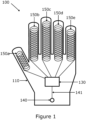
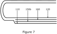
- glove 100 comprises outer layer 110, inner layer 120, circuit board 130, ground buttons 140 and 142 (connected via wires 141 and 143), a plurality of monopole aerials 150a, 150b, 150c, 150d, and 150e (collectively aerials 150), and dielectric layer 160.
- Figures 1 , 2, and 3 show various views of glove 100.
- Each of aerials 150 comprise about 3 meters of 40 gauge polyurethane-insulated copper Litz wire, with the bulk of the wire arranged in a coil lying flat on the top side of each finger of the glove, with a short, generally straight, wire segment extending towards and connects to circuit board 130.
- the coiled portion is about 18 mm wide, and the total length of the coiled segment plus the straight segment of aerials 150b, 150c, 150d, and 150e is about 100 mm; the total length of the coiled segment and the straight segment of aerial 150a (the thumb) is about 70 mm.
- the flattened coils When worn, the flattened coils will bend slightly to fit the shape of the user's finger, and the coiled portion of each of aerials 150 will extend from around the knuckle of each user's finger to the tip of each user's finger. However importantly, when worn, no portion of any of aerials 150 extends beyond the user's fingertips so that the presence of the aerials will not interfere with use of the glove for typical work-related activities such as picking up and holding objects.
- Ground buttons 140 and 141 comprise conductive material and are intended to contact the skin of the user's hand at the user's wrist when worn.
- glove 100 includes a Velcro wrist strap (not shown) to secure the glove 100 such that the inner sides of ground buttons 140 and 142 make electrical contact with the user's hand.
- Ground button 140 is electrically connected to circuit board 130 via wire 141 and to ground button 142 by wire 143.
- Ground button 140, ground button 142, and wire 143 are sewn to the inner side of outer layer 110 at the wrist of glove 100, such that at least a portion of the ground buttons 140 and 142 are exposed to the user's wrist through openings in inner layer 120.
- Aerials 150 are positioned into the fingers of glove 100 between dielectric layer 160 and outer layer 110, and are mechanically attached to dielectric layer 160 with adhesive.
- Dielectric layer 160 is 3 mm neoprene which prevents leakage of any AC voltage detected by aerials 150 into the user's hand.
- Dielectric layer 160 extends through the top side of each finger of glove 100 (under the coiled portions of aerials 150) and across the back of glove 100 (under aerials 150 and circuit board 130).
- Outer layer 110 protects the user's hand, aerials 150, and circuit board 130 from mechanical risks, and is made from cowhide grain leather.
- Inner layer 120 comprises cotton material that provides user comfort and separates the user's hand from direct contact with circuit board 130 and dielectric layer 160. Outer layer 110 and inner layer 120 both follow the shape of a user's hand and are sewn together at the wrist portions of each as well as other portions as needed to keep inner layer 120 in a generally-fixed position within outer layer 110.
- Circuit board 130 comprises conventional low-power electronics for processing signals from aerials 150.
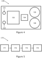
- Figure 4 shows the logical layout of circuit board 130, including aerial connector 131 (to which aerials 150 are connected), ground connector 132 (to which wire 141 is connected), AC voltage detection components 133 (which comprise various resistors, capacitors, transistors, traces, and the like, as needed to perform the functions described in block diagram 170), surface mount buzzer 134, and surface mount coin cell holders 135 and 136 (suitable for holding two CR2032 3v coin cell batteries which provide power to circuit board 130).
- the components of circuit board 130 are physically arranged to provide optimal performance as would be known to one of ordinary skill in the art of designing circuit board layout.
- Block diagram 170 describes the functionality of the components of circuit board 130 when a signal arrives from aerials 150.
- the electrical signal from aerials 150 first passes through band pass filter 171, which eliminates very low and very high frequency signals, for example, low-frequency static fields and highfrequency fields caused by switch-mode power supplies.
- the signal output from bandpass filter 171 then passes through frequency comparator 172, which compares the filtered signal with a reference signal. When the filtered signal has a higher frequency than that of the reference signal, the output of comparator 172 is low, and when the filtered signal has a lower frequency than that of the reference signal, the output of comparator 172 is high.
- the signal output from comparator 172 is a square wave with a frequency equal to that of the electrical signal received by aerials 150.
- This signal feeds into peak detector 173, which outputs a DC voltage equal to the peak value of the signal from comparator 172.
- the output of peak detector 173 drives the circuitry of audio annunciator 174 which emits an audible alert when it receives a sufficient signal.
- the detected voltage results in an audible alert from annunciator 174, and when aerials 150 are not in proximity to commercial AC voltage, annunciator 174 will remain silent.
- inventive glove as described in the foregoing embodiment may be modified and/or extended by one of ordinary skill in the art, so long as the glove (a) maintains its usefulness as a glove and (b) maintains its ability to detect AC voltage at a safe distance. Selection of some of these modifications and extensions may affect the quality of the general operation of the inventive glove in terms of performance when used for particular applications. Other modifications and extensions may be driven by costs of manufacture, availability of materials, physical constraints, and other factors which may be independent of the general operation of the inventive glove. The following variations represent a non-exclusive description of examples of other embodiments which may be mixed and matched as needed and as technically feasible without affecting the general functionality of the inventive glove, as long as they fall within the scope of the claims, which solely define the scope of the invention.
- outer layer 110 comprises material suitable for use in specific applications.
- outer layer 110 may comprise natural or synthetic materials, including cotton, wool, canvas, rubber, latex, nylon, neoprene, nitrile, polyvinyl, polyethylene, silk, Kevlar, metal fiber, and the like, along with blends of such materials.
- outer layer 110 may further comprise outer coatings such as polyurethane, Teflon, nitrile, and latex.
- a portion of outer layer 110 may comprise one material while another portion may comprise other materials, for example, the front side of the fingertips of glove 100 may comprise material that enhances the user's grip, while the wrist portion may be made from flexible material that enhances the fit of glove 100.
- inner layer 120 comprises material suitable for use in specific applications.
- inner layer 120 may comprise nature or synthetic materials, including silk, wool, leather, and the like, along with blends of such materials.
- inner layer 120 is fully attached to outer layer 110 using thread, adhesive, or other suitable means commonly known to those of ordinary skill in the art.
- the length, configuration, and composition of aerials 150 may vary provided that (a) aerials 150 remain sufficiently sensitive to AC voltage at a safe distance and (b) the variations do not hinder the usability of the glove in terms of weight and/or flexibility.
- aerials 150 may comprise thinner or thicker gauges of wire and may comprise solid (non-Litz) wire.
- aerials 150 may be arranged in a configuration other than in overlapping coils, for example the wires may be positioned in side-by-side runs that are parallel, orthogonal, or diagonal with respect to a line between the knuckle and fingertip portions of glove 100.
- the length and configurations of aerials 150 may be tuned for optimized performance for a particular frequency of AC voltage.
- the total wire length of aerials 150 may vary according to the size of the gloves and lengths of the glove fingers.
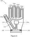
- aerials 150 may comprise serpentine printed circuits on circuit board 130, where circuit board 130 comprises a single or multilayer flexible dielectric substrate such as polyimide or polyester. As shown in Figure 6 , in such embodiments, circuit board 130 extends through the top of the fingers of glove 100 and through a portion of the back and wrist of glove 100, including a portion 130a that comprises pads where AC voltage detection components 133, surface mount buzzer 134, and surface mount coin cell holders 135 and 136 may be mounted. Additionally, printed circuits on circuit board 130 provide direct and indirect connections between aerials 150, the components mounted on portion 130a, and ground buttons 140 and 141. In some related embodiments, the dielectric substrate of circuit board 130 may also serve as dielectric layer 160.
- circuit board 130 comprises a single or multilayer flexible dielectric substrate such as polyimide or polyester.
- circuit board 130 extends through the top of the fingers of glove 100 and through a portion of the back and wrist of glove 100, including a portion 130a that comprises pads where AC voltage detection components 133, surface mount buzzer 134, and
- circuit board portion 130a may be a discrete circuit board that may be connected to circuit board 130 using conventional edge connector technology. In some related embodiments, some of the electrical components may be mounted at locations on circuit board 130 other than portion 130a. In some related embodiments, dielectric layer 160 may be positioned only under circuit board 130, while in other embodiments, dielectric layer 160 may extend to the entire back and wrist of glove 100.
- aerials 150 may be located on the bottom of the fingers of glove 100 instead of on the top of the fingers of glove 100.
- the bottom of the fingers of glove 100 comprises dielectric layer 160 adjacent to inner layer 120 and aerials 150 between dielectric layer 160 and outer layer 110. Because this configuration places aerials 150 on the "working" side of glove 100, some additional measures may be required to protect aerials 150; for example, outer layer 110 may need to be thicker, composed of stronger material, and/or include multiple layers, and aerials 150 may comprise printed circuits on a flexible circuit board which may be part of circuit board 130 or may be a separate circuit board connected to circuit board 130 and located in the back or palm of the glove 100. Because such additional measures may reduce the sensitivity of aerials 150 to detect an external AC voltage, aerials 150 may extend into the palm of glove 100.
- ground contact there may be a single ground contact and it may be located elsewhere on glove 100, for example, as a ground button positioned on the front or back side of the wrist, or there may be multiple ground buttons at various locations designed to make contact with the user's hand.
- the ground contact may be a ribbon, rivet, or strip of conductive material positioned to make contact with the user's hand, for example, by surrounding the wrist of the glove.
- the ground contact may also function as a snap, button, hook, or zipper used to adjust the fit of glove 100.
- the ground contact may be glued, sewn, or riveted in place.
- glove 100 may be secured to the user's wrist using means suitable for the application of glove 100.
- it may be secured using elastic sewn into or otherwise attached to the wrist of glove 100, adjustable straps, snaps, or stretchable material.
- dielectric layer 160 may comprise thicker or thinner neoprene or other flexible dielectric material, provided that the thickness or composition of the material does not adversely affect the weight or flexibility of glove 100. Further, dielectric layer 160 may comprise a coating or paint which enhances its dielectric properties while allowing for use of a thinner material.
- annunciator 174 may provide other alert mechanisms instead of or in addition to an audible alert.
- annunciator 174 may comprise multiple LEDs that indicate different conditions, such as solid green for "detector functioning, no danger” and flashing red for “danger.”
- the audible alert could change pitch or volume in proportion to the proximity and/or strength of the AC voltage.
- annunciator 174 may include a haptic indicator that vibrates when dangerous AC voltage is detected; such an indicator may prove useful in noisy environments.
- the functionality provided by some or all of the components of printed circuit board 130 could be performed by an application-specific integrated circuit (ASIC).
- ASIC application-specific integrated circuit
- Use of an ASIC could reduce the footprint of the circuitry mounted on printed circuit board 130 and thus reduce the size and weight of printed circuit board 130.
- the functionality provided by some or all of the components of printed circuit board 130 could be performed by a low-power microcontroller.
- Use of a programmable microcontroller could, for example, provide better analysis of detected signals to reduce false positives, provide a greater degree of customizable features such as optimizing glove 100 for particular operating environments, extracting additional information about detected signals such as strength, frequency, and harmonic distortion, and logging of significant events in the microcontroller's non-volatile memory for later access. Significant events may include, for example, the detection of dangerous voltage, power on/off, configuration changes, recalibration, and the like.
- the addition of a GPS receiver to circuit board 130 could provide location to the information logged about significant events.
- the presence of a programmable microcontroller could simplify external connectivity as described in the following paragraph.
- circuit board 130 further comprises communications hardware for connecting glove 100 to an external device such as a portable computer, smart phone, or computer network.
- the communications hardware may include a wired connector, such as a USB or Lightning port, or it may include wireless radio transceiver suitable for use with Bluetooth, ZigBee, IEEE 802.11x, or other wireless protocols.
- the presence of a microcontroller as part of the circuitry present on circuit board 130 simplifies external communications since such microcontrollers may include integrated transceivers and embedded protocol stacks.
- the power source for circuit board 130 may comprise rechargeable batteries, which can be recharged by physical connection of glove 100 to a power source, for example, via a USB cable, by placing glove 100 in proximity to a wireless charging pad, by a kinetic energy charger incorporated into glove 100, or by the electric field that glove 100 is designed to detect. In the latter embodiment, an energy storage circuit would be required to store small amount of energy collected by the electric field.
- the signals received via aerials 150 at circuit board 130 could be conditioned prior to passing through band pass filter 171.
- conditioning may include the use of a large resistor connected to ground to ensure that the input to band pass filter 171 remains low except in the absence of AC voltage.
- Circuit board 130 may also include components to match the impedance of aerials 150 in order to maximize signal received by band pass filter 171.
- the signals received via aerials 130 could be individually processed and analyzed; such individual signal processing could provide, for example, additional information about the physical position of the AC voltage with respect to aerials 150.
- the ends of the glove fingers may be exposed, for example, to allow the user to have physical contact with some external device such as a computer touch-screen.
- some external device such as a computer touch-screen.
- the finger portions of outer layer 110, inner layer 120, and dielectric layer 160 will not extend to the fingertips.
- Aerials 150 may be shortened, at the expense of lowered sensitivity, or alternatively, to maintain sensitivity, the coiled portions of aerials 150 may extend into the back portion of glove 100 or may be coiled more densely.
- the functionality of the components of circuit board 130 may be configurable, either manually or dynamically.
- the AC voltage is 60 Hz while in Australia, AC voltage is 50 Hz.
- a manual switch on glove 100 could change the circuitry from one frequency to another, or alternatively, the circuitry could be automatically configured to the proper frequency by holding glove 100 near an active AC voltage conductor.
- an additional aerial configured to transmit an AC voltage signal, could be incorporated into glove 100. This would allow the components of circuit board 130 to be tested periodically to confirm proper operation.
- a low-voltage detection circuit could be incorporated in the components of circuit board 130. This could alert the user that power source (for example, the on-board batteries) were too weak for proper operation.
- a motion detector such as an accelerometer, could sense when glove 100 was not in use and put the components of circuit board 130 into a low power sleep mode; the motion detector could also sense when glove 100 was in use, putting the components of circuit board 130 back into normal operation mode.
- glove 100 may include a power switch that allows the user to turn the power to circuit board 130 on and off.
Landscapes
- Engineering & Computer Science (AREA)
- Textile Engineering (AREA)
- Physics & Mathematics (AREA)
- General Physics & Mathematics (AREA)
- Life Sciences & Earth Sciences (AREA)
- Biophysics (AREA)
- Gloves (AREA)
- Investigating Or Analyzing Materials By The Use Of Electric Means (AREA)
- Glass Compositions (AREA)
Claims (14)
- Handschuh zur berührungslosen Wechselspannungsdetektion (100), Folgendes umfassend:eine äußere Schicht (110) in Form einer menschlichen Hand, und die einen Handrücken, ein Handgelenk, eine Handfläche und eine Vielzahl von Fingern umfasst, wobei jeder Finger einen oberen Abschnitt und einen unteren Abschnitt umfasst;eine innere Schicht (120) in Form einer menschlichen Hand, die einen Handrücken, ein Handgelenk, eine Handfläche und eine Vielzahl von Fingern umfasst, wobei jeder Finger einen oberen Abschnitt und einen unteren Abschnitt umfasst, wobei die innere Schicht in die äußere Schicht passt;eine flexible dielektrische Schicht (160), die (a) zwischen dem oberen Abschnitt jedes Fingers der äußeren Schicht und dem oberen Abschnitt jedes Fingers der inneren Schicht, (b) zwischen dem Handrücken der äußeren Schicht und dem Handrücken der inneren Schicht und (c) zwischen dem Handgelenk der äußeren Schicht und dem Handgelenk der inneren Schicht positioniert ist; unddadurch gekennzeichnet, dass der Handschuh zur berührungslosen Wechselspannungsdetektion Folgendes umfasst:
eine flexible Leiterplatte (130), die zwischen der dielektrischen Schicht und der äußeren Schicht positioniert ist, wobei die flexible Leiterplatte Folgendes umfasst:ein dielektrisches Substrat;eine Vielzahl von schlangenförmigen gedruckten Schaltungen, wobei sich jede schlangenförmige gedruckte Schaltung von ungefähr dem Grundknöchel jedes Fingers bis ungefähr zum distalen Ende jedes Fingers erstreckt und wobei jede schlangenförmige gedruckte Schaltung als Monopolantenne (150, 150a, 150b, 150c, 150d, 150e) fungiert;eine Vielzahl von elektronischen Komponenten, wobei die Vielzahl von elektronischen Komponenten einen Tiefpassfilter, einen Hochpassfilter, einen Spannungsdetektor (133), eine Stromversorgung, einen Melder (174) und einen Erdungskontakt (140, 141) umfasst;eine Vielzahl von Kontaktstellen zum Anschließen der Vielzahl von elektronischen Komponenten; undeine Vielzahl von gedruckten Schaltungen, welche die Vielzahl von schlangenförmigen gedruckten Schaltungen und die Vielzahl von Kontaktstellen verbindet;wobei der Erdungskontakt leitfähiges Material umfasst und am Handgelenk der inneren Schicht positioniert ist, undwobei der Melder konfiguriert ist, um einen Benutzer des Handschuhs zu warnen, wenn der Spannungsdetektor eine Annäherung einer Wechselspannung an die Antennen feststellt. - Handschuh nach Anspruch 1,
wobei der Tiefpassfilter, der Hochpassfilter und der Spannungsdetektor unter Verwendung diskreter Schaltungen implementiert sind. - Handschuh nach Anspruch 1,wobei die Vielzahl von elektronischen Komponenten ferner eine anwendungsspezifische integrierte Schaltung (ASIC) umfasst, undwobei der Tiefpassfilter, der Hochpassfilter und der Spannungsdetektor auf der ASIC implementiert sind.
- Handschuh nach Anspruch 1,
wobei die Vielzahl von elektronischen Komponenten ferner einen Mikrocontroller umfasst, wobei der Mikrocontroller einen Prozessor und einen nichtflüchtigen Speicher umfasst, und wobei:der nichtflüchtige Speicher Anweisungen zum Durchführen von Berechnungen umfasst, die mit der Implementierung von mindestens einem von dem Tiefpassfilter, dem Hochpassfilter und dem Spannungsdetektor in Zusammenhang stehen, oderder nichtflüchtige Speicher Anweisungen zum Speichern der Ergebnisse von Berechnungen umfasst, die mit der Implementierung von mindestens einem von Tiefpassfilter, Hochpassfilter und Spannungsdetektor in Zusammenhang stehen. - Handschuh nach Anspruch 1,
wobei die dielektrische Schicht Neopren mit einer Dicke von ungefähr 3 mm umfasst. - Handschuh nach Anspruch 1,
wobei der Melder konfiguriert ist, um den Benutzer vor der Nähe der Wechselspannung zu warnen, durch:Ausgeben eines Tons;Anzeigen eines visuellen Indikators; oderBereitstellen eines haptischen Indikators. - Handschuh zur berührungslosen Wechselspannungsdetektion (100), Folgendes umfassend:eine äußere Schicht (110) in Form einer menschlichen Hand, und die einen Handrücken, ein Handgelenk, eine Handfläche und eine Vielzahl von Fingern umfasst, wobei jeder Finger einen oberen Abschnitt und einen unteren Abschnitt umfasst;eine innere Schicht (120) in Form einer menschlichen Hand, die einen Handrücken, ein Handgelenk, eine Handfläche und eine Vielzahl von Fingern umfasst, wobei jeder Finger einen oberen Abschnitt und einen unteren Abschnitt umfasst, wobei die innere Schicht in die äußere Schicht passt; unddadurch gekennzeichnet, dass der Handschuh zur berührungslosen Wechselspannungsdetektion Folgendes umfasst:
eine flexible Leiterplatte (130), die (a) zwischen dem oberen Abschnitt jedes Fingers der äußeren Schicht und dem oberen Abschnitt jedes Fingers der inneren Schicht, (b) zwischen dem Handrücken der äußeren Schicht und dem Handrücken der inneren Schicht und (c) zwischen dem Handgelenk der äußeren Schicht und dem Handgelenk der inneren Schicht positioniert ist, wobei die flexible Leiterplatte Folgendes umfasst:ein dielektrisches Substrat;eine Vielzahl von schlangenförmigen gedruckten Schaltungen, wobei sich jede schlangenförmige gedruckte Schaltung von ungefähr dem Grundknöchel jedes Fingers bis ungefähr zum distalen Ende jedes Fingers erstreckt und wobei jede schlangenförmige gedruckte Schaltung als Monopolantenne (150, 150a, 150b, 150c, 150d, 150e) fungiert;eine Vielzahl von elektronischen Komponenten, wobei die Vielzahl von elektronischen Komponenten einen Tiefpassfilter, einen Hochpassfilter, einen Spannungsdetektor (133), eine Stromversorgung, einen Melder (174) und einen Erdungskontakt (140, 141) umfasst;eine Vielzahl von Kontaktstellen zum Anschließen der Vielzahl von elektronischen Komponenten; undeine Vielzahl von gedruckten Schaltungen, welche die Vielzahl von schlangenförmigen gedruckten Schaltungen und die Vielzahl von elektronischen Komponenten verbindet;wobei der Erdungskontakt ein leitfähiges Material umfasst und am Handgelenk der inneren Schicht positioniert ist, undwobei der Melder konfiguriert ist, um einen Benutzer des Handschuhs zu warnen, wenn der Spannungsdetektor eine Annäherung einer Wechselspannung an die Antennen feststellt. - Handschuh nach Anspruch 7,
wobei der Tiefpassfilter, der Hochpassfilter und der Spannungsdetektor unter Verwendung diskreter Schaltungen implementiert sind. - Handschuh nach Anspruch 7,wobei die Vielzahl von elektronischen Komponenten ferner eine anwendungsspezifische integrierte Schaltung (ASIC) umfasst, undwobei der Tiefpassfilter, der Hochpassfilter und der Spannungsdetektor auf der ASIC implementiert sind.
- Handschuh nach Anspruch 7,wobei die Vielzahl von elektronischen Komponenten ferner einen Mikrocontroller umfasst, undwobei der Mikrocontroller einen Prozessor und einen nichtflüchtigen Speicher umfasst,wobei:der nichtflüchtige Speicher Anweisungen zum Durchführen von Berechnungen umfasst, die mit der Implementierung von mindestens einem von dem Tiefpassfilter, dem Hochpassfilter und dem Spannungsdetektor in Zusammenhang stehen, oderder nichtflüchtige Speicher Anweisungen zum Speichern der Ergebnisse von Berechnungen umfasst, die mit der Implementierung von mindestens einem von Tiefpassfilter, Hochpassfilter und Spannungsdetektor in Zusammenhang stehen.
- Handschuh nach Anspruch 1 oder 7,
wobei die äußere Schicht aus einem oder mehreren Materialien besteht, die aus der Gruppe ausgewählt sind, bestehend aus Leder, Baumwolle, Wolle, Leinwand, Gummi, Latex, Nylon, Neopren, Nitril, Polyvinyl, Polyethylen, Seide, Kevlar, Polyurethan, Teflon und Metallfasern. - Handschuh nach Anspruch 1 oder 7,
wobei die innere Schicht aus einem oder mehreren Materialien besteht, die aus der Gruppe ausgewählt sind, bestehend aus Baumwolle, Seide, Wolle und Leder. - Handschuh zur berührungslosen Wechselspannungsdetektion (100), Folgendes umfassend:eine äußere Schicht (110) in Form einer menschlichen Hand, und die einen Handrücken, ein Handgelenk, eine Handfläche und eine Vielzahl von Fingern umfasst, wobei jeder Finger einen oberen Abschnitt und einen unteren Abschnitt umfasst;eine innere Schicht (120) in Form einer menschlichen Hand, die einen Handrücken, ein Handgelenk, eine Handfläche und eine Vielzahl von Fingern umfasst, wobei jeder Finger einen oberen Abschnitt und einen unteren Abschnitt umfasst, wobei die innere Schicht in die äußere Schicht passt; unddadurch gekennzeichnet, dass der Handschuh zur berührungslosen Wechselspannungsdetektion Folgendes umfasst:
eine erste flexible Leiterplatte (130), die zwischen dem unteren Teil jedes Fingers der äußeren Schicht und dem unteren Teil jedes Fingers der inneren Schicht positioniert ist, wobei die erste flexible Leiterplatte Folgendes umfasst:ein dielektrisches Substrat; undeine Vielzahl von schlangenförmigen gedruckten Schaltungen, wobei sich jede schlangenförmige gedruckte Schaltung von etwa dem Grundknöchel jedes Fingers bis etwa zum distalen Ende jedes Fingers erstreckt und wobei jede schlangenförmige gedruckte Schaltung als Monopolantenne (150, 150a, 150b, 150c, 150d, 150e) fungiert;eine zweite flexible Leiterplatte, die zwischen der äußeren Schicht und der inneren Schicht positioniert ist, wobei die zweite flexible Leiterplatte Folgendes umfasst:ein dielektrisches Substrat;eine Vielzahl von elektronischen Komponenten, wobei die Vielzahl von elektronischen Komponenten einen Tiefpassfilter, einen Hochpassfilter, einen Spannungsdetektor (133), eine Stromversorgung, einen Melder (174) und einen Erdungskontakt (140, 141) umfasst;eine Vielzahl von Kontaktstellen zum Anschließen der Vielzahl von elektronischen Komponenten; undeine Vielzahl von gedruckten Schaltungen, welche die Vielzahl von schlangenförmigen gedruckten Schaltungen mit der Vielzahl von Kontaktstellen verbindet;wobei der Erdungskontakt ein leitfähiges Material umfasst und am Handgelenk der inneren Schicht positioniert ist, undwobei der Melder konfiguriert ist, um einen Benutzer des Handschuhs zu warnen, wenn der Spannungsdetektor eine Annäherung einer Wechselspannung an die Antennen feststellt. - Handschuh nach Anspruch 1, wobei die dielektrische Schicht Neopren mit einer Dicke von weniger als 3 mm umfasst.
Applications Claiming Priority (2)
| Application Number | Priority Date | Filing Date | Title |
|---|---|---|---|
| PCT/IB2019/001379 WO2021136951A1 (en) | 2019-12-31 | 2019-12-31 | Glove with integrated voltage detector |
| PCT/IB2020/057572 WO2021136986A1 (en) | 2019-12-31 | 2020-08-12 | Glove with intergrated voltage detector |
Publications (4)
| Publication Number | Publication Date |
|---|---|
| EP4084642A1 EP4084642A1 (de) | 2022-11-09 |
| EP4084642A4 EP4084642A4 (de) | 2024-02-28 |
| EP4084642C0 EP4084642C0 (de) | 2025-03-26 |
| EP4084642B1 true EP4084642B1 (de) | 2025-03-26 |
Family
ID=76685878
Family Applications (1)
| Application Number | Title | Priority Date | Filing Date |
|---|---|---|---|
| EP20909372.3A Active EP4084642B1 (de) | 2019-12-31 | 2020-08-12 | Handschuh mit integriertem spannungsdetektor |
Country Status (7)
| Country | Link |
|---|---|
| US (2) | US11602182B2 (de) |
| EP (1) | EP4084642B1 (de) |
| JP (1) | JP7245575B2 (de) |
| KR (1) | KR102528997B1 (de) |
| AU (1) | AU2020418583B2 (de) |
| CA (1) | CA3163354C (de) |
| WO (2) | WO2021136951A1 (de) |
Families Citing this family (3)
| Publication number | Priority date | Publication date | Assignee | Title |
|---|---|---|---|---|
| AU2021226164B2 (en) * | 2020-02-25 | 2022-12-01 | Grant Edward STAPLES | Wrist-band voltage detector |
| KR102823350B1 (ko) * | 2023-04-17 | 2025-06-20 | 주식회사 피앤씨솔루션 | 전도성 실을 이용한 웨어러블 활선 감지 장갑 |
| KR102820038B1 (ko) * | 2024-09-10 | 2025-06-11 | 문이연 | 즉각적인 피드백이 가능한 웨어러블 검전 장치 |
Family Cites Families (25)
| Publication number | Priority date | Publication date | Assignee | Title |
|---|---|---|---|---|
| US10488174B2 (en) | 2018-03-06 | 2019-11-26 | General Electric Company | Systems and methods for wearable voltage detection devices |
| JP4845981B2 (ja) | 2009-03-04 | 2011-12-28 | 三菱電機プラントエンジニアリング株式会社 | 電圧警報器 |
| US20110234414A1 (en) | 2010-03-26 | 2011-09-29 | Luis Ojeda | Wearable live electrical circuit detection device |
| CN104781660A (zh) | 2012-07-11 | 2015-07-15 | 电力研究所有限公司 | 挠性涡电流探测器 |
| CN202980268U (zh) | 2012-12-14 | 2013-06-12 | 杭州元城建筑工程有限公司 | 一种具有测电功能的防护手套 |
| WO2014158030A1 (en) | 2013-03-24 | 2014-10-02 | Maihi Henare Waata | Electrical energy detection glove |
| US20160095369A1 (en) * | 2014-10-02 | 2016-04-07 | Gerbings, LLC. | Heated glove and method of manufacturing |
| CN107077207B (zh) * | 2014-10-17 | 2020-10-27 | 雅马哈株式会社 | 数据手套 |
| CN104569561B (zh) | 2014-12-20 | 2018-07-06 | 国家电网公司 | 一种具有高压警示功能的绝缘手套 |
| CN204409675U (zh) | 2014-12-20 | 2015-06-24 | 国家电网公司 | 一种可探测危险电压的绝缘手套 |
| US20160209448A1 (en) | 2015-01-16 | 2016-07-21 | Robert H. Currie | Voltage Detector Safety Glove |
| US20170099888A1 (en) | 2015-10-12 | 2017-04-13 | Kevin James Flynn | Electrical safety device |
| KR101818988B1 (ko) * | 2016-02-16 | 2018-01-16 | 전종환 | 전류 및 전압 측정 기능을 포함하는 절연 장갑 |
| KR101747247B1 (ko) * | 2016-04-06 | 2017-06-21 | 주식회사 더원소프트 | 스마트 발열 장갑과 이를 이용한 제어시스템 |
| US11045123B2 (en) * | 2017-03-29 | 2021-06-29 | Graftworx, Inc. | Wearable device with multimodal diagnostics |
| US9939468B1 (en) | 2017-05-05 | 2018-04-10 | Michael J. Dyszel | Wearable non contacting AC voltage detection system |
| US10247763B1 (en) | 2017-09-29 | 2019-04-02 | E I Du Pont De Nemours And Company | Voltage detecting glove |
| CN207639713U (zh) | 2017-11-27 | 2018-07-24 | 国家电网公司 | 一种具有漏电报警功能的绝缘手套 |
| CN107898028A (zh) | 2017-12-27 | 2018-04-13 | 刘仁奎 | 一种多功能绝缘手套 |
| CL2018000026A1 (es) * | 2018-01-04 | 2018-03-23 | Sainz Flores Renato Andres | Dispositivo detector de tensión eléctrica aplicado a guantes de seguridad para detectar la presencia de tensión eléctrica en cables, máquinas o equipos para disminuir riesgos de accidentes por electrocución |
| US10837599B2 (en) | 2018-02-08 | 2020-11-17 | Alken Inc. | Safety system for machinery |
| US20200029635A1 (en) * | 2018-07-26 | 2020-01-30 | Microsoft Technology Licensing, Llc | Motion-restricting wearable safety device |
| US10802657B1 (en) * | 2019-02-12 | 2020-10-13 | Facebook Technologies, Llc | System and method for detecting mutual capacitance |
| US11412793B2 (en) * | 2019-11-21 | 2022-08-16 | Feel The Same, Inc. | Soft sensor-embedded glove and method for manufacturing same |
| US11187732B2 (en) * | 2019-12-27 | 2021-11-30 | Michael Casillas | Voltage sensing glove assembly |
-
2019
- 2019-12-31 US US17/049,396 patent/US11602182B2/en active Active
- 2019-12-31 WO PCT/IB2019/001379 patent/WO2021136951A1/en not_active Ceased
-
2020
- 2020-08-12 KR KR1020227025915A patent/KR102528997B1/ko active Active
- 2020-08-12 WO PCT/IB2020/057572 patent/WO2021136986A1/en not_active Ceased
- 2020-08-12 CA CA3163354A patent/CA3163354C/en active Active
- 2020-08-12 EP EP20909372.3A patent/EP4084642B1/de active Active
- 2020-08-12 US US17/293,467 patent/US11712076B2/en active Active
- 2020-08-12 JP JP2022549241A patent/JP7245575B2/ja active Active
- 2020-08-12 AU AU2020418583A patent/AU2020418583B2/en active Active
Also Published As
| Publication number | Publication date |
|---|---|
| CA3163354A1 (en) | 2021-07-08 |
| EP4084642A1 (de) | 2022-11-09 |
| AU2020418583B2 (en) | 2023-02-02 |
| EP4084642C0 (de) | 2025-03-26 |
| EP4084642A4 (de) | 2024-02-28 |
| KR102528997B1 (ko) | 2023-05-03 |
| WO2021136986A1 (en) | 2021-07-08 |
| WO2021136951A1 (en) | 2021-07-08 |
| JP7245575B2 (ja) | 2023-03-24 |
| US20220256954A1 (en) | 2022-08-18 |
| US11602182B2 (en) | 2023-03-14 |
| CA3163354C (en) | 2024-01-02 |
| KR20220113828A (ko) | 2022-08-16 |
| US20220322771A1 (en) | 2022-10-13 |
| AU2020418583A1 (en) | 2022-08-11 |
| US11712076B2 (en) | 2023-08-01 |
| JP2022554040A (ja) | 2022-12-27 |
Similar Documents
| Publication | Publication Date | Title |
|---|---|---|
| EP4084642B1 (de) | Handschuh mit integriertem spannungsdetektor | |
| US10247763B1 (en) | Voltage detecting glove | |
| US20130152272A1 (en) | Protective Glove with Conductive Stitching | |
| JP6874279B2 (ja) | ウェアラブル機器における電波シールド装置 | |
| US11762002B2 (en) | Wrist-band voltage detector | |
| US4868710A (en) | Clean room garment | |
| CN205214311U (zh) | 针对上班族的智能腰带 | |
| CN106137191A (zh) | 一种电子设备及信息处理方法 | |
| US20180168506A1 (en) | Modular intelligent clothing | |
| JP7828516B2 (ja) | 装着品、及び、読取システム | |
| CN105224078B (zh) | 运动数据捕捉设备 | |
| CN211299992U (zh) | 手指康复训练器具 | |
| CN207640400U (zh) | 可以根据心率值提供感知反馈的心率带 | |
| CN207586444U (zh) | 手持式金属探测器 |
Legal Events
| Date | Code | Title | Description |
|---|---|---|---|
| STAA | Information on the status of an ep patent application or granted ep patent |
Free format text: STATUS: THE INTERNATIONAL PUBLICATION HAS BEEN MADE |
|
| PUAI | Public reference made under article 153(3) epc to a published international application that has entered the european phase |
Free format text: ORIGINAL CODE: 0009012 |
|
| STAA | Information on the status of an ep patent application or granted ep patent |
Free format text: STATUS: REQUEST FOR EXAMINATION WAS MADE |
|
| 17P | Request for examination filed |
Effective date: 20220526 |
|
| AK | Designated contracting states |
Kind code of ref document: A1 Designated state(s): AL AT BE BG CH CY CZ DE DK EE ES FI FR GB GR HR HU IE IS IT LI LT LU LV MC MK MT NL NO PL PT RO RS SE SI SK SM TR |
|
| DAV | Request for validation of the european patent (deleted) | ||
| DAX | Request for extension of the european patent (deleted) | ||
| REG | Reference to a national code |
Ref country code: DE Free format text: PREVIOUS MAIN CLASS: A41D0019000000 Ref country code: DE Ref legal event code: R079 Ref document number: 602020048532 Country of ref document: DE Free format text: PREVIOUS MAIN CLASS: A41D0019000000 Ipc: G01R0019000000 |
|
| A4 | Supplementary search report drawn up and despatched |
Effective date: 20240131 |
|
| RIC1 | Information provided on ipc code assigned before grant |
Ipc: A41D 19/015 20060101ALI20240125BHEP Ipc: A41D 31/26 20190101ALI20240125BHEP Ipc: H05K 1/14 20060101ALI20240125BHEP Ipc: G01R 19/00 20060101AFI20240125BHEP |
|
| REG | Reference to a national code |
Ref legal event code: R079 Ipc: G01R0019150000 Ref country code: DE Ref legal event code: R079 Ref document number: 602020048532 Country of ref document: DE Free format text: PREVIOUS MAIN CLASS: G01R0019000000 Ipc: G01R0019150000 |
|
| RIC1 | Information provided on ipc code assigned before grant |
Ipc: A41D 19/01 20060101ALI20240829BHEP Ipc: G01R 19/15 20060101AFI20240829BHEP |
|
| GRAP | Despatch of communication of intention to grant a patent |
Free format text: ORIGINAL CODE: EPIDOSNIGR1 |
|
| STAA | Information on the status of an ep patent application or granted ep patent |
Free format text: STATUS: GRANT OF PATENT IS INTENDED |
|
| INTG | Intention to grant announced |
Effective date: 20241016 |
|
| GRAS | Grant fee paid |
Free format text: ORIGINAL CODE: EPIDOSNIGR3 |
|
| GRAA | (expected) grant |
Free format text: ORIGINAL CODE: 0009210 |
|
| STAA | Information on the status of an ep patent application or granted ep patent |
Free format text: STATUS: THE PATENT HAS BEEN GRANTED |
|
| AK | Designated contracting states |
Kind code of ref document: B1 Designated state(s): AL AT BE BG CH CY CZ DE DK EE ES FI FR GB GR HR HU IE IS IT LI LT LU LV MC MK MT NL NO PL PT RO RS SE SI SK SM TR |
|
| REG | Reference to a national code |
Ref country code: GB Ref legal event code: FG4D |
|
| REG | Reference to a national code |
Ref country code: CH Ref legal event code: EP |
|
| REG | Reference to a national code |
Ref country code: DE Ref legal event code: R096 Ref document number: 602020048532 Country of ref document: DE |
|
| REG | Reference to a national code |
Ref country code: IE Ref legal event code: FG4D |
|
| U01 | Request for unitary effect filed |
Effective date: 20250417 |
|
| U07 | Unitary effect registered |
Designated state(s): AT BE BG DE DK EE FI FR IT LT LU LV MT NL PT RO SE SI Effective date: 20250425 |
|
| PG25 | Lapsed in a contracting state [announced via postgrant information from national office to epo] |
Ref country code: RS Free format text: LAPSE BECAUSE OF FAILURE TO SUBMIT A TRANSLATION OF THE DESCRIPTION OR TO PAY THE FEE WITHIN THE PRESCRIBED TIME-LIMIT Effective date: 20250626 |
|
| PG25 | Lapsed in a contracting state [announced via postgrant information from national office to epo] |
Ref country code: NO Free format text: LAPSE BECAUSE OF FAILURE TO SUBMIT A TRANSLATION OF THE DESCRIPTION OR TO PAY THE FEE WITHIN THE PRESCRIBED TIME-LIMIT Effective date: 20250626 |
|
| PG25 | Lapsed in a contracting state [announced via postgrant information from national office to epo] |
Ref country code: HR Free format text: LAPSE BECAUSE OF FAILURE TO SUBMIT A TRANSLATION OF THE DESCRIPTION OR TO PAY THE FEE WITHIN THE PRESCRIBED TIME-LIMIT Effective date: 20250326 |
|
| PG25 | Lapsed in a contracting state [announced via postgrant information from national office to epo] |
Ref country code: GR Free format text: LAPSE BECAUSE OF FAILURE TO SUBMIT A TRANSLATION OF THE DESCRIPTION OR TO PAY THE FEE WITHIN THE PRESCRIBED TIME-LIMIT Effective date: 20250627 |
|
| PG25 | Lapsed in a contracting state [announced via postgrant information from national office to epo] |
Ref country code: SM Free format text: LAPSE BECAUSE OF FAILURE TO SUBMIT A TRANSLATION OF THE DESCRIPTION OR TO PAY THE FEE WITHIN THE PRESCRIBED TIME-LIMIT Effective date: 20250326 |
|
| PG25 | Lapsed in a contracting state [announced via postgrant information from national office to epo] |
Ref country code: ES Free format text: LAPSE BECAUSE OF FAILURE TO SUBMIT A TRANSLATION OF THE DESCRIPTION OR TO PAY THE FEE WITHIN THE PRESCRIBED TIME-LIMIT Effective date: 20250326 |
|
| PG25 | Lapsed in a contracting state [announced via postgrant information from national office to epo] |
Ref country code: PL Free format text: LAPSE BECAUSE OF FAILURE TO SUBMIT A TRANSLATION OF THE DESCRIPTION OR TO PAY THE FEE WITHIN THE PRESCRIBED TIME-LIMIT Effective date: 20250326 |
|
| PG25 | Lapsed in a contracting state [announced via postgrant information from national office to epo] |
Ref country code: SK Free format text: LAPSE BECAUSE OF FAILURE TO SUBMIT A TRANSLATION OF THE DESCRIPTION OR TO PAY THE FEE WITHIN THE PRESCRIBED TIME-LIMIT Effective date: 20250326 |
|
| PG25 | Lapsed in a contracting state [announced via postgrant information from national office to epo] |
Ref country code: IS Free format text: LAPSE BECAUSE OF FAILURE TO SUBMIT A TRANSLATION OF THE DESCRIPTION OR TO PAY THE FEE WITHIN THE PRESCRIBED TIME-LIMIT Effective date: 20250726 |
|
| U21 | Renewal fee for the european patent with unitary effect paid with additional fee |
Year of fee payment: 6 Effective date: 20251002 |
|
| PGFP | Annual fee paid to national office [announced via postgrant information from national office to epo] |
Ref country code: GB Payment date: 20251002 Year of fee payment: 6 |
|
| PG25 | Lapsed in a contracting state [announced via postgrant information from national office to epo] |
Ref country code: CZ Free format text: LAPSE BECAUSE OF FAILURE TO SUBMIT A TRANSLATION OF THE DESCRIPTION OR TO PAY THE FEE WITHIN THE PRESCRIBED TIME-LIMIT Effective date: 20250326 |
|
| PLBE | No opposition filed within time limit |
Free format text: ORIGINAL CODE: 0009261 |
|
| STAA | Information on the status of an ep patent application or granted ep patent |
Free format text: STATUS: NO OPPOSITION FILED WITHIN TIME LIMIT |
|
| REG | Reference to a national code |
Ref country code: CH Ref legal event code: L10 Free format text: ST27 STATUS EVENT CODE: U-0-0-L10-L00 (AS PROVIDED BY THE NATIONAL OFFICE) Effective date: 20260211 |
|
| 26N | No opposition filed |
Effective date: 20260105 |
|
| REG | Reference to a national code |
Ref country code: CH Ref legal event code: H13 Free format text: ST27 STATUS EVENT CODE: U-0-0-H10-H13 (AS PROVIDED BY THE NATIONAL OFFICE) Effective date: 20260324 |
|
| PG25 | Lapsed in a contracting state [announced via postgrant information from national office to epo] |
Ref country code: MC Free format text: LAPSE BECAUSE OF FAILURE TO SUBMIT A TRANSLATION OF THE DESCRIPTION OR TO PAY THE FEE WITHIN THE PRESCRIBED TIME-LIMIT Effective date: 20250326 |
|
| PG25 | Lapsed in a contracting state [announced via postgrant information from national office to epo] |
Ref country code: CH Free format text: LAPSE BECAUSE OF NON-PAYMENT OF DUE FEES Effective date: 20250831 |
|
| U1N | Appointed representative for the unitary patent procedure changed after the registration of the unitary effect |
Representative=s name: MARKS & CLERK LLP; GB |