EP4084677B1 - Modellbasierte therapieparameter für herzversagen - Google Patents
Modellbasierte therapieparameter für herzversagen Download PDFInfo
- Publication number
- EP4084677B1 EP4084677B1 EP20910361.3A EP20910361A EP4084677B1 EP 4084677 B1 EP4084677 B1 EP 4084677B1 EP 20910361 A EP20910361 A EP 20910361A EP 4084677 B1 EP4084677 B1 EP 4084677B1
- Authority
- EP
- European Patent Office
- Prior art keywords
- therapy
- patient
- pacing
- data
- model
- Prior art date
- Legal status (The legal status is an assumption and is not a legal conclusion. Google has not performed a legal analysis and makes no representation as to the accuracy of the status listed.)
- Active
Links
Images








Classifications
-
- A—HUMAN NECESSITIES
- A61—MEDICAL OR VETERINARY SCIENCE; HYGIENE
- A61B—DIAGNOSIS; SURGERY; IDENTIFICATION
- A61B5/00—Measuring for diagnostic purposes; Identification of persons
- A61B5/02—Detecting, measuring or recording for evaluating the cardiovascular system, e.g. pulse, heart rate, blood pressure or blood flow
- A61B5/02028—Determining haemodynamic parameters not otherwise provided for, e.g. cardiac contractility or left ventricular ejection fraction
-
- A—HUMAN NECESSITIES
- A61—MEDICAL OR VETERINARY SCIENCE; HYGIENE
- A61B—DIAGNOSIS; SURGERY; IDENTIFICATION
- A61B5/00—Measuring for diagnostic purposes; Identification of persons
- A61B5/24—Detecting, measuring or recording bioelectric or biomagnetic signals of the body or parts thereof
- A61B5/316—Modalities, i.e. specific diagnostic methods
- A61B5/318—Heart-related electrical modalities, e.g. electrocardiography [ECG]
- A61B5/346—Analysis of electrocardiograms
- A61B5/349—Detecting specific parameters of the electrocardiograph cycle
- A61B5/361—Detecting fibrillation
-
- A—HUMAN NECESSITIES
- A61—MEDICAL OR VETERINARY SCIENCE; HYGIENE
- A61B—DIAGNOSIS; SURGERY; IDENTIFICATION
- A61B5/00—Measuring for diagnostic purposes; Identification of persons
- A61B5/48—Other medical applications
- A61B5/4836—Diagnosis combined with treatment in closed-loop systems or methods
-
- A—HUMAN NECESSITIES
- A61—MEDICAL OR VETERINARY SCIENCE; HYGIENE
- A61B—DIAGNOSIS; SURGERY; IDENTIFICATION
- A61B5/00—Measuring for diagnostic purposes; Identification of persons
- A61B5/68—Arrangements of detecting, measuring or recording means, e.g. sensors, in relation to patient
- A61B5/6846—Arrangements of detecting, measuring or recording means, e.g. sensors, in relation to patient specially adapted to be brought in contact with an internal body part, i.e. invasive
- A61B5/6847—Arrangements of detecting, measuring or recording means, e.g. sensors, in relation to patient specially adapted to be brought in contact with an internal body part, i.e. invasive mounted on an invasive device
- A61B5/686—Permanently implanted devices, e.g. pacemakers, other stimulators, biochips
-
- A—HUMAN NECESSITIES
- A61—MEDICAL OR VETERINARY SCIENCE; HYGIENE
- A61B—DIAGNOSIS; SURGERY; IDENTIFICATION
- A61B5/00—Measuring for diagnostic purposes; Identification of persons
- A61B5/72—Signal processing specially adapted for physiological signals or for diagnostic purposes
- A61B5/7271—Specific aspects of physiological measurement analysis
- A61B5/7285—Specific aspects of physiological measurement analysis for synchronizing or triggering a physiological measurement or image acquisition with a physiological event or waveform, e.g. an ECG signal
- A61B5/7292—Prospective gating, i.e. predicting the occurrence of a physiological event for use as a synchronisation signal
-
- A—HUMAN NECESSITIES
- A61—MEDICAL OR VETERINARY SCIENCE; HYGIENE
- A61B—DIAGNOSIS; SURGERY; IDENTIFICATION
- A61B5/00—Measuring for diagnostic purposes; Identification of persons
- A61B5/74—Details of notification to user or communication with user or patient; User input means
- A61B5/7475—User input or interface means, e.g. keyboard, pointing device, joystick
-
- A—HUMAN NECESSITIES
- A61—MEDICAL OR VETERINARY SCIENCE; HYGIENE
- A61N—ELECTROTHERAPY; MAGNETOTHERAPY; RADIATION THERAPY; ULTRASOUND THERAPY
- A61N1/00—Electrotherapy; Circuits therefor
- A61N1/18—Applying electric currents by contact electrodes
- A61N1/32—Applying electric currents by contact electrodes alternating or intermittent currents
- A61N1/36—Applying electric currents by contact electrodes alternating or intermittent currents for stimulation
- A61N1/362—Heart stimulators
- A61N1/3627—Heart stimulators for treating a mechanical deficiency of the heart, e.g. congestive heart failure or cardiomyopathy
-
- A—HUMAN NECESSITIES
- A61—MEDICAL OR VETERINARY SCIENCE; HYGIENE
- A61N—ELECTROTHERAPY; MAGNETOTHERAPY; RADIATION THERAPY; ULTRASOUND THERAPY
- A61N1/00—Electrotherapy; Circuits therefor
- A61N1/18—Applying electric currents by contact electrodes
- A61N1/32—Applying electric currents by contact electrodes alternating or intermittent currents
- A61N1/36—Applying electric currents by contact electrodes alternating or intermittent currents for stimulation
- A61N1/362—Heart stimulators
- A61N1/365—Heart stimulators controlled by a physiological parameter, e.g. heart potential
-
- A—HUMAN NECESSITIES
- A61—MEDICAL OR VETERINARY SCIENCE; HYGIENE
- A61B—DIAGNOSIS; SURGERY; IDENTIFICATION
- A61B5/00—Measuring for diagnostic purposes; Identification of persons
- A61B5/72—Signal processing specially adapted for physiological signals or for diagnostic purposes
- A61B5/7271—Specific aspects of physiological measurement analysis
- A61B5/7275—Determining trends in physiological measurement data; Predicting development of a medical condition based on physiological measurements, e.g. determining a risk factor
Definitions
- the present technology is generally related to heart failure and, in particular, to determining therapy parameters for heart failure therapy.
- Heart failure refers to a pathophysiologic disorder broadly defined by an inability of a patient's heart to pump sufficiently to cope with its venous return or to deliver sufficient output to meet the metabolic demands of the body (for example, during physical activity or in severe cases at rest).
- Congestive heart failure symptoms may be indicative of congestive heart failure.
- Congestive heart failure symptoms may include reduced cardiac output leading to easy fatigue and organ dysfunction (for example, renal dysfunction), as well as congestion either in the lungs, which may cause breathlessness, or peripherally, which may lead to swelling of the lower limbs and abdomen.
- the size of the chambers of the heart may be decreased, which may occur as a result of increased muscle thickness.
- a range of further sub-classifications or structure of the heart may be applied based on symptoms exhibited by the patient.
- Some classifications of HF by symptoms or objective assessments, for example, are provided by the New York Heart Association (classes I-IV, classes A-D)).
- the abnormal diastolic function may manifest as an increase in the stiffness of the heart's left ventricle (LV), a decrease in LV relaxation when filling with blood before the next beat, and decreased chamber volume, which may occur as a result of increased muscle thickness.
- Patients experiencing HFpEF may also experience other co-morbidities such as atrial fibrillation (AF) and pulmonary hypertension.
- AF atrial fibrillation
- US 2019/298903 A1 relates to a left ventricular assist device adjustment and evaluation.
- the techniques of this disclosure generally relate to heart failure and, in particular, to determining therapy parameters for heart failure (HF) therapy.
- Heart failure patients such as patients having heart failure with preserved ejection fraction (HFpEF)
- cardiac therapy such as pacing therapy
- pacing therapy which may result in cardiac remodeling of the patient's heart.
- Cardiac remodeling may be beneficial in some cases or adverse in other cases.
- the present disclosure provides techniques for managing cardiac remodeling in a manner that is tailored to an individual patient or a particular group of patients, in particular, by using a cardiovascular (CV) model to facilitate determination of one or more therapy parameters.
- the present techniques may increase efficacy of cardiac therapy, such as HFpEF therapy using elevated heart rate (HR) pacing.
- HR heart rate
- the present disclosure provides a therapy management method including: determining that a patient has heart failure with preserved ejection fraction (HFpEF); configuring a cardiovascular (CV) model using patient characterization data; determining one or more therapy parameters using output data of the CV model; and administering HFpEF therapy based on the one or more therapy parameters.
- HFpEF preserved ejection fraction
- CV cardiovascular
- the present disclosure provides a non-transient computer-readable storage medium having computing instructions stored thereon that, when executed by processing circuitry, cause the processing circuitry to perform operations as defined in the therapy management method.
- the present disclosure provides a controller including an input interface configured to receive patient characterization data; an output interface configured to provide therapy parameter data; and processing circuitry operably coupled to the input interface and the output interface
- the processing circuitry is configured to: receive the patient characterization data in response to determining that a patient has heart failure with preserved ejection fraction (HFpEF); configure a cardiovascular (CV) model using the patient characterization data; determine one or more therapy parameters using output data of the CV model; and provide therapy parameter data including the one or more therapy parameters to the output interface.
- HFpEF preserved ejection fraction
- CV cardiovascular
- the present disclosure provides a system including: one or more patient characterization devices to provide patient characterization data; an implantable medical device (IMD) configured to provide heart failure with preserved ejection fraction (HFpEF) pacing therapy; and processing circuitry operably coupled to the one or more patient characterization devices and the implantable medical device.
- the processing circuitry is configured to: receive the patient characterization data in response to determining that a patient has HFpEF; configure a cardiovascular (CV) model using the patient characterization data; determine one or more therapy parameters using output data of the CV model; and configure the IMD to provide HFpEF pacing therapy based on the one or more therapy parameters.
- CV cardiovascular
- the techniques of this disclosure generally relate to heart failure and, in particular, to determining therapy parameters for heart failure (HF) therapy.
- Heart failure patients such as patients having heart failure with preserved ejection fraction (HFpEF)
- cardiac therapy such as pacing therapy
- pacing therapy which may result in cardiac remodeling of the patient's heart.
- Cardiac remodeling may be beneficial in some cases or adverse in other cases.
- the present disclosure provides techniques for managing cardiac remodeling in a manner that is tailored to an individual patient or a particular group of patients, in particular, by using a cardiovascular (CV) model to facilitate determination of one or more therapy parameters.
- the present techniques may increase efficacy of cardiac therapy, such as HFpEF therapy using elevated heart rate (HR) pacing.
- HR heart rate
- HF may be treated using cardiac pacing therapy.
- Cardiac therapy may be, or include, HFpEF therapy to treat patients having HFpEF.
- HFpEF therapy may include periodic high, or elevated, heart rate (HR) pacing. Elevated heart rate pacing for HFpEF therapy may remodel the patient's heart.
- HR heart rate
- HFpEF therapy may also be described as cardiac remodeling pacing therapy. Any suitable technique for cardiac remodeling pacing therapy may be used known to one skilled in the art having the benefit of the present disclosure. Non-limiting examples of cardiac remodeling pacing therapy are described in U.S. Patent No. 9,403,016 (Meyer), issued August 2, 2016 , and U.S. Patent No. 9,737,772 (Meyer), issued August 22, 2017 .
- HFpEF therapy is configured to manage the delivery of elevated HR pacing, for example, by using a CV model to facilitate predicting the remodeling response of the patient.
- the HFpEF therapy may stop elevated HR pacing based on output data from the CV model to prevent increasing the volume of the patient's heart beyond a certain threshold, which may be described as a dilatation threshold.
- the HFpEF therapy may be managed to balance the diastolic and systolic functions. Such management may prevent excessive dilatation and HFrEF.
- Cardiac therapy may be provided by implantable medical devices (IMDs), which may be programmable based on one or more therapy parameters. Therapy provided by IMDs for cardiac disease may be delivered effectively by tailoring therapy to individual patients.
- Patient characterization data may be collected for feedback, for example, from an electrode apparatus (for example, an electrocardiogram (ECG)) or echocardiogram.
- ECG electrocardiogram
- Patient characterization data may be used to predict chronic remodeling in a therapy modeling system.
- prediction of chronic remodeling using the therapy modeling system may be based on configuring a cardiovascular (CV) model with patient characterization data.
- the CV model may also be described as, or include, a physiologic model representative of at least part of the patient's cardiovascular system.
- the therapy modeling system may determine and recommend appropriate therapy parameters for patients based on output data of the CV model.
- the CV model may be used to determine that pacing therapy is not predicted to lead to remodeling (dilatation) and is predicted to provide hemodynamic benefits, in which case, pacing therapy may continue.
- Programmable IMD therapy for cardiac disease may be delivered more effectively by tailoring therapy to an individual patient or particular group of patients.
- the therapy parameters may be determined to be optimal therapy parameters to provide therapeutic effect to the individual patient or particular group of patients.
- the patient characterization data may be used to determine a patient classification, such as a patient cohort or patient micro-cohort, which may be used to configure the CV model to provide targeted output data to more accurately indicate a predicted patient response to cardiac therapy.
- Therapy parameters determined by the therapy modeling system based on the targeted output data may be optimal for the patient in the cohort or micro-cohort.
- the therapy modeling system may provide generic patient descriptors to characterize a patient cohort.
- a generic patient descriptor may classify the patient as having HFpEF with concentric hypertrophy or as having HFpEF without concentric hypertrophy.
- Other descriptions of phenotypes of cardiac disease may also be provided based on patient history data, which may be based on prior testing recorded in an electronic medical record (EMR), or may be driven by particular parameters measured from the patient during, or in advance of, a programming session with or without patient history data.
- EMR electronic medical record
- recommended therapy parameters from the therapy modeling system may be used for initial IMD or other medical device programming and may also be used during one or more patient follow-ups.
- the initial CV model may be configured based on patient baseline data alone.
- the CV model may be updated in a follow-up CV model, which may be configured based on patient response data at a "point in time" after administering cardiac therapy.
- patient characterization data refers to data based on measurements or other stored data about a patient or about a particular group with which the patient is associated.
- patient characterization data may be based on measured data, such as clinical measurement data (for example, "point in time” measurements in a clinical setting), ambulatory measurement data (for example, recorded by an IMD or other ambulatory medical device), or both.
- Non-limiting examples of clinical measurement data include clinician input, electrode apparatus data, echocardiogram data, imaging data, patient history data, hemodynamic measurement data, or IMD data.
- Non-limiting examples of ambulatory measurement data include daily or night heart rate, heart rate variability, patient activity levels, contractility measures, or cardiac auscultation or heart sounds.
- patient response data refers to a type of patient characterization data based on measurements after administering cardiac therapy.
- Patient response data may be measured in the same or similar manner to other patient characterization data.
- Patient response data may be based on measured data, such as clinical measurement data, ambulatory measurement data, or both.
- various therapy parameters may be recommended by the therapy modeling system.
- the therapy modeling system may also provide recommendation of therapy "aggressiveness" based on the patient's prior response to therapy.
- the patient's prior response may be determined from ambulatory diagnostic measurements or "point-in-time" measurements, such as serial echocardiographic data or other means of measuring progression of remodeling.
- the high rate pacing HFpEF therapy may result in cardiac dilation.
- the therapy modeling system may provide recommendations to stop therapy or reduce aggressiveness based on generic patient classifications or specific patient measurements of cardiac dilation or structure compared to predetermined thresholds.
- the therapy modeling system may also increase aggressiveness based on lack of evidence of cardiac structure changes.
- the therapy modeling system may incorporate a "cloud-based" system and be accessible over the internet.
- the therapy modeling system may receive, or request, patient characterization data and provide recommendations to the clinician, for example, on a user interface device.
- the therapy modeling system may be based on a device programmer, or on a stand-alone computer, that provides information during programmer sessions.
- automated approaches may combine the cloud-based system with a programmer, or other device, to create an integrated system for programming recommendations.
- a fully automated approach to the therapy modeling system may be fully implemented in an IMD and programmer system, which may not need to access the cloud.
- HF and particularly HFpEF therapy the techniques of this disclosure may also be adapted for other types of implantable therapy devices, such as cardiac resynchronization therapy (CRT) devices or left ventricular assist devices (LVADs).
- CRT cardiac resynchronization therapy
- LVADs left ventricular assist devices
- a CV model may be used to manage various therapies by simulating the patient's response to such therapies.
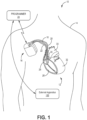
- the IMD 16 may sense, among other things, electrical signals attendant to the depolarization and repolarization of the heart 12 via electrodes coupled to at least one of the leads 18, 20, 22.
- the IMD 16 provides pacing therapy (for example, pacing pulses) to the heart 12 based on the electrical signals sensed within the heart 12.
- the IMD 16 may be operable to adjust one or more parameters associated with the pacing therapy such as, for example, pulse duration, voltage amplitude, burst length, etc. Further, the IMD 16 may be operable to use various electrode configurations to deliver pacing therapy, which may be unipolar or bipolar.
- the IMD 16 may also provide defibrillation therapy or cardioversion therapy via electrodes located on at least one of the leads 18, 20, 22.
- the IMD 16 may detect arrhythmia of the heart 12, such as fibrillation of the ventricles 28, 32, and deliver defibrillation therapy to the heart 12 in the form of electrical pulses.
- IMD 16 may be programmed to deliver a progression of therapies, for example, pulses with increasing energy levels, until a fibrillation of heart 12 is stopped.
- the therapy delivery system 10 may include one or more leadless IMDs (not shown). Any suitable leadless IMD may be included, such as leaded IMDs, leadless IMDs, or intracardiac IMDs.
- One or more leaded or leadless electrodes may be coupled to the housing of an IMD.
- An IMD having only leadless electrodes may be described as a leadless IMD.
- a leadless IMD may include a leadlet, which may extend from a chamber of the heart into to another location in the heart 12 or in the vasculature of the patient 14.
- a “leadless” electrode refers to an electrode operably coupled to a device being free of a lead, or without using a lead, extending between the electrode and the housing of the device.
- One or more devices of the therapy delivery system 10 may include a motion sensor 38.
- the motion sensor may be configured to sense mechanical activity of the patient 14 or of the patient's heart 12.
- the motion sensor 38 may be configured to sense at least mechanical activity of one or both atria (left, right, or both) of the patient's heart 12.
- Non-limiting examples of a motion sensor include an inertial measurement unit (IMU), such as an accelerometer, gyroscope, or magneto-sensors.
- IMU inertial measurement unit
- the therapy delivery system 10 may be operably coupled to a therapy modeling system 200 ( FIG. 4 ).
- the therapy delivery system 10 may receive one or more therapy parameters to deliver cardiac therapy to the patient 14.
- the therapy delivery system 10 may deliver and manage cardiac therapy to a patient experiencing or having HFpEF to appropriately manage HFpEF therapy based on the one or more therapy parameters from the therapy modeling system 200.
- a programmer 24 which may be a handheld computing device, a computer workstation, or other user interface device for a user, such as a physician, technician, another clinician, or patient, to communicate with the IMD 16 (for example, to program the IMD 16).
- the user may interact with the programmer 24 to retrieve information concerning one or more detected or indicated faults associated within the IMD 16 or the pacing therapy delivered therewith.
- the IMD 16 and the programmer 24 may communicate via wireless communication using any suitable techniques. Examples of communication techniques may include, for example, low frequency or radiofrequency (RF) telemetry, but other techniques are also contemplated.
- RF radiofrequency
- the programmer 24 may be operably coupled to a network or the internet to facilitate communication between the IMD 16 and other devices.
- the programmer 24 may be described as an access point or communication link.
- the programmer 24 may also be described as having a transceiver.
- the programmer 24 may be used to operably couple the IMD 16 to a therapy modeling system 200 ( FIG. 4 ).
- the therapy delivery system 10 may include an external apparatus 100 positionable outside of the body of the patient 14.
- the external apparatus 100 may be positioned proximate to the body.
- the external apparatus 100 may include one or more components to facilitate evaluation of various implantation locations (such as spatial location, implant depth, etc.) or pacing settings (such as pulse width, pulse timing, pulse amplitude, etc.). For example, implantation location of or pacing delivered by one or more electrodes of the IMD 16.
- the external apparatus 100 may include one or more of an electrode apparatus, a display apparatus, and a computing apparatus as will be described further herein with respect to FIGS. 6-8 .
- FIG. 2 is a schematic diagram that illustrates the exemplary cardiac therapy delivery system of FIG. 1 in more detail.
- the leads 18, 20, 22 may be electrically coupled to a therapy delivery module (for example, for delivery of pacing therapy), a sensing module (for example, one or more electrodes to sense or monitor electrical activity of the heart 12 for use in determining effectiveness of pacing therapy), or any other modules of the IMD 16 via a connector block 34.
- the proximal ends of the leads 18, 20, 22 may include electrical contacts that electrically couple to respective electrical contacts within the connector block 34 of the IMD 16.
- the leads 18, 20, 22 may be mechanically coupled to the connector block 34 with the aid of set screws, connection pins, or another suitable mechanical coupling mechanism.
- Each of the leads 18, 20, 22 includes an elongated insulative lead body, which may carry a number of conductors (for example, concentric coiled conductors, straight conductors, etc.) separated from one another by insulation (for example, tubular insulative sheaths).
- bipolar electrodes 40, 42 are located proximate to a distal end of the lead 18.
- the bipolar electrodes 44, 46 are located proximate to a distal end of the lead 20 and the bipolar electrodes 48, 50 are located proximate to a distal end of the lead 22.
- the electrodes 40, 44, 48 may take the form of ring electrodes, and the electrodes 42, 46, 50 may take the form of extendable helix tip electrodes mounted retractably within the insulative electrode heads 52, 54, 56, respectively.
- Each of the electrodes 40, 42, 44, 46, 48, 50 may be electrically coupled to a respective one of the conductors (for example, coiled or straight) within the lead body of its associated lead 18, 20, 22, and thereby coupled to respective ones of the electrical contacts on the proximal end of the leads 18, 20, 22.
- the IMD 16 includes one or more housing electrodes, such as housing electrode 58, which may be formed integrally with an outer surface of a housing 60 (for example, hermetically-sealed housing) of the IMD 16 or otherwise coupled to the housing 60.
- housing electrode 58 any of the electrodes 40, 42, 44, 46, 48, 50 may be used for unipolar sensing or pacing in combination with housing electrode 58.
- any of electrodes 40, 42, 44, 46, 48, 50, 58 may be used in combination to form a sensing vector, for example, a sensing vector that may be used to evaluate or analysis the effectiveness of pacing therapy.
- a configuration sensing and pacing may be seen with respect to U.S. Patent No.
- 9,002,454 filed Dec. 23, 2011 which is incorporated by reference in its entirety, which may be modified by using an LV tip -RV coil (such as electrode 46 and electrode 62, respectively) for the pacing vector and the sensing vector.
- the LV tip to RV coil vector may be better for performing impedance measurements. This impedance may be inversely correlated to LV chamber size and may drop as the LV chamber dilates with remodeling pacing. It is generally understood by those skilled in the art having the benefit of this disclosure that other electrodes can also be selected as pacing and sensing vectors.
- the housing 60 may enclose a therapy delivery module that may include a stimulation generator for generating cardiac pacing pulses and defibrillation or cardioversion shocks, as well as a sensing module for monitoring the patient's heart rhythm.
- the leads 18, 20, 22 may also include elongated electrodes 62, 64, 66, respectively, which may take the form of a coil.
- the IMD 16 may deliver defibrillation shocks to the heart 12 via any combination of the elongated electrodes 62, 64, 66 and the housing electrode 58.
- the electrodes 58, 62, 64, 66 may also be used to deliver cardioversion pulses to the heart 12.
- the electrodes 62, 64, 66 may be fabricated from any suitable electrically conductive material, such as, but not limited to, platinum, platinum alloy, or other materials known to be usable in implantable defibrillation electrodes. Since electrodes 62, 64, 66 are not generally configured to deliver pacing therapy, any of electrodes 62, 64, 66 may be used to sense electrical activity during pacing therapy (for example, for use in analyzing pacing therapy effectiveness) and may be used in combination with any of electrodes 40, 42, 44, 46, 48, 50, 58.
- the RV elongated electrode 62 may be used to sense electrical activity of a patient's heart during the delivery of pacing therapy (for example, in combination with the housing electrode 58 forming a RV elongated, coil, or defibrillation electrode-to-housing electrode vector).
- the atrial lead 22 is positioned near the AV nodal/septal area for delivery of His bundle pacing (and may sense or pace the RA or LA) and either the ventricle lead 18 is positioned in the right ventricle or the ventricle lead 20 positioned in the left ventricle, or both ventricle leads 18 and 20 may be included, as described below.
- the electrode 50 of lead 22 may take the form of a helical tip electrode to enable the lead to be fixedly engaged near the AV nodal/septal area for delivery of His bundle pacing, described below.
- FIG. 3 is a conceptual diagram that illustrates one example of a configuration of the IMD 16.
- the IMD 16 may include processing circuitry, which may include a control module 81 (or controller), a therapy delivery module 84 (or therapy delivery circuitry), which may include a stimulation generator, a sensing module 86 (or sensing circuitry), and a power source 90.
- processing circuitry may include a control module 81 (or controller), a therapy delivery module 84 (or therapy delivery circuitry), which may include a stimulation generator, a sensing module 86 (or sensing circuitry), and a power source 90.
- the control module 81 may include a processor 80, memory 82, and a telemetry module 88.
- the IMD 16 may also include a motion sensor 38 ( FIG. 2 ) operably coupled to the processor 80, for example, through the sensing module 86.
- the memory 82 may include computer-readable instructions that, when executed, for example, by the processor 80, cause the IMD 16 or the control module 81 to perform various functions attributed to the IMD 16 or the control module 81 described herein. Further, the memory 82 may include any volatile, non-volatile, magnetic, optical, or electrical media, such as a random-access memory (RAM), read-only memory (ROM), non-volatile RAM (NVRAM), electrically erasable programmable ROM (EEPROM), flash memory, or any other digital media.
- RAM random-access memory
- ROM read-only memory
- NVRAM non-volatile RAM
- EEPROM electrically erasable programmable ROM
- flash memory or any other digital media.
- Memory 82 includes computer instructions related to capture management, including the method of capture management according to the present disclosure, described in detail below.
- memory 82 includes computer instructions for one or more pacing regimen(s) (for example, one or more pacing algorithm(s)).
- one or more pacing algorithms of the present disclosure may be dynamically employed to up-titrate or down-titrate cardiac rhythms and heart rates.
- one or more pacing algorithms pace the heart at an elevated heart rate for a specified duration followed by pacing the heart at a second heart rate level for another pre-specified duration of time.
- one or more pacing algorithms pace the heart at a first elevated rate and a first duration.
- one or more pacing algorithms pace the heart at a first elevated pacing rate (for example, up to 30 heart beats per minute above resting heart rate for up to 10 minutes or up to 20 minutes.
- the pacing rate is elevated to a second elevated pacing rate (for example, up to 20 HBPM above the first elevated heart rate for up to 10 or 20 minutes).
- a third pacing rate is delivered to allow the heart to beat more slowly than the second elevated pacing rate.
- a fourth pacing rate lower than the third pacing rate, is delivered to the heart through a pacemaker.
- the heart rate is allowed to gradually return to a resting heart rate level (with or without pacing).
- Multiple other pacing regimens are disclosed herein that may be employed by a pacemaker in order to remodel the heart.
- the processor 80 (also referred to as processor circuit) of the control module 81 may include any one or more of a microprocessor, a controller, a digital signal processor (DSP), an application specific integrated circuit (ASIC), a field-programmable gate array (FPGA), or equivalent discrete or integrated logic circuitry.
- the processor 80 may include multiple components, such as any combination of one or more microprocessors, one or more controllers, one or more DSPs, one or more ASICs, or one or more FPGAs, as well as other discrete or integrated logic circuitry.
- the functions attributed to the processor 80 herein may be embodied as software, firmware, hardware, or any combination thereof.
- the control module 81 may control the therapy delivery module 84 to deliver therapy (for example, electrical stimulation therapy such as pacing) to the heart 12 according to a selected one or more therapy programs, which may be stored in the memory 82. More, specifically, the control module 81 (for example, the processor 80) may control the therapy delivery module 84 to deliver electrical stimulus such as, for example, pacing pulses with the amplitudes, pulse widths, frequency, or electrode polarities specified by the selected one or more therapy programs (for example, pacing therapy programs, pacing recovery programs, capture management programs, etc.).
- therapy for example, electrical stimulation therapy such as pacing
- the control module 81 may control the therapy delivery module 84 to deliver electrical stimulus such as, for example, pacing pulses with the amplitudes, pulse widths, frequency, or electrode polarities specified by the selected one or more therapy programs (for example, pacing therapy programs, pacing recovery programs, capture management programs, etc.).
- the therapy delivery module 84 is electrically coupled to electrodes 40, 42, 44, 46, 48, 50, 58, 62, 64, 66, for example, via conductors of the respective lead 18, 20, 22, or, in the case of housing electrode 58, via an electrical conductor disposed within housing 60 of IMD 16.
- Therapy delivery module 84 may be configured to generate and deliver electrical stimulation therapy such as pacing therapy to the heart 12 using one or more of the electrodes 40, 42, 44, 46, 48, 50, 58, 62, 64, 66.
- therapy delivery module 84 may deliver pacing stimulus (for example, pacing pulses) via ring electrodes 40, 44, 48 coupled to leads 18, 20, and 22, respectively, or helical tip electrodes 42, 46, and 50 of leads 18, 20, and 22, respectively. Further, for example, therapy delivery module 84 may deliver defibrillation shocks to heart 12 via at least two of electrodes 58, 62, 64, 66. In some examples, therapy delivery module 84 may be configured to deliver pacing, cardioversion, or defibrillation stimulation in the form of electrical pulses. In other examples, therapy delivery module 84 may be configured to deliver one or more of these types of stimulation in the form of other signals, such as sine waves, square waves, or other substantially continuous time signals.
- pacing stimulus for example, pacing pulses
- therapy delivery module 84 may deliver defibrillation shocks to heart 12 via at least two of electrodes 58, 62, 64, 66.
- therapy delivery module 84 may be configured to deliver pacing, cardioversion,
- the IMD 16 may further include a switch module 85 and the control module 81 (for example, the processor 80) may use the switch module 85 to select, for example, via a data/address bus, which of the available electrodes are used to deliver therapy such as pacing pulses for pacing therapy, or which of the available electrodes are used for sensing.
- the switch module 85 may include a switch array, switch matrix, multiplexer, or any other type of switching device suitable to selectively couple the sensing module 86 or the therapy delivery module 84 to one or more selected electrodes. More specifically, the therapy delivery module 84 may include a plurality of pacing output circuits.
- Each pacing output circuit of the plurality of pacing output circuits may be selectively coupled, for example, using the switch module 85, to one or more of the electrodes 40, 42, 44, 46, 48, 50, 58, 62, 64, 66 (for example, a pair of electrodes for delivery of therapy to a pacing vector).
- each electrode can be selectively coupled to one of the pacing output circuits of the therapy delivery module using the switching module 85.
- the sensing module 86 is coupled (for example, electrically coupled) to sensing apparatus, which may include, among additional sensing apparatus, the electrodes 40, 42, 44, 46, 48, 50, 58, 62, 64, 66 to monitor electrical activity of the heart 12, for example, electrocardiogram (ECG)/electrogram (EGM) signals, etc.
- ECG/EGM signals may be used to analyze a plurality of paced events. More specifically, one or more morphological features of each paced event within the ECG/EGM signals may be used to determine whether each paced event has a predetermined level of effectiveness.
- the ECG/EGM signals may be further used to monitor heart rate (HR), heart rate variability (HRV), heart rate turbulence (HRT), deceleration/acceleration capacity, deceleration sequence incidence, T-wave alternans (TWA), P-wave to P-wave intervals (also referred to as the P-P intervals or A-A intervals), R-wave to R-wave intervals (also referred to as the R-R intervals or V-V intervals), P-wave to QRS complex intervals (also referred to as the P-R intervals, A-V intervals, or P-Q intervals), QRS-complex morphology, ST segment (the segment that connects the QRS complex and the T-wave), T-wave changes, QT intervals, electrical vectors, etc.
- HR heart rate
- HRV heart rate variability
- HRT heart rate turbulence
- deceleration/acceleration capacity deceleration sequence incidence
- TWA T-wave alternans
- P-wave to P-wave intervals
- the switch module 85 may be also be used with the sensing module 86 to select which of the available electrodes are used to, for example, sense electrical activity of the patient's heart (for example, one or more electrical vectors of the patient's heart using any combination of the electrodes 40, 42, 44, 46, 48, 50, 58, 62, 64, 66).
- the control module 81 may select the electrodes that function as sensing electrodes via the switch module within the sensing module 86, for example, by providing signals via a data/address bus.
- the sensing module 86 may include one or more sensing channels, each of which may include an amplifier.
- sensing module 86 includes a channel that includes an amplifier with a relatively wider pass band than the R-wave or P-wave amplifiers. Signals from the selected sensing electrodes that are selected for coupling to this wide-band amplifier may be provided to a multiplexer, and thereafter converted to multi-bit digital signals by an analog-to-digital converter for storage in memory 82 as an EGM. In some examples, the storage of such EGMs in memory 82 may be under the control of a direct memory access circuit.
- the control module 81 (for example, using the processor 80) may employ digital signal analysis techniques to characterize the digitized signals stored in memory 82 to analyze or classify one or more morphological waveforms of the EGM signals to determine pacing therapy effectiveness.
- the processor 80 may be configured to determine, or obtain, one or more features of one or more sensed morphological waveforms within one or more electrical vectors of the patient's heart and store the one or more features within the memory 82 for use in determining effectiveness of pacing therapy at a later time.
- the control module 81 may include a pacer timing and control module, which may be embodied as hardware, firmware, software, or any combination thereof.
- the pacer timing and control module may include one or more dedicated hardware circuits, such as an ASIC, separate from the processor 80, such as a microprocessor, or a software module executed by a component of processor 80, which may be a microprocessor or ASIC.
- the pacer timing and control module may include programmable counters which control the basic time intervals associated with DDD, VVI, DVI, VDD, AAI, DDI, DDDR, VVIR, DVIR, VDDR, AAIR, DDIR and other modes of single and dual chamber pacing.
- D may indicate dual chamber
- V may indicate a ventricle
- I may indicate inhibited pacing (for example, no pacing)
- A may indicate an atrium
- R may indicate rate responsive.
- the first letter in the pacing mode may indicate the chamber that is paced
- the second letter may indicate the chamber in which an electrical signal is sensed
- the third letter may indicate the chamber in which the response to sensing is provided.
- Intervals defined by the pacer timing and control module within control module 81 may include atrial and ventricular pacing escape intervals, refractory periods during which sensed P-waves and R-waves are ineffective to restart timing of the escape intervals, or the pulse widths of the pacing pulses.
- the pacer timing and control module may define a blanking period and provide signals from sensing module 86 to blank one or more channels, for example, amplifiers, for a period during and after delivery of electrical stimulation to the heart 12. The durations of these intervals may be determined in response to stored data in memory 82.
- the pacer timing and control module of the control module 81 may also determine the amplitude of the cardiac pacing pulses.
- escape interval counters within the pacer timing/control module may be reset upon sensing of R-waves and P-waves.
- Therapy delivery module 84 (for example, including a stimulation generator) may include one or more pacing output circuits that are coupled, for example, selectively by the switch module 85, to any combination of electrodes 40, 42, 44, 46, 48, 50, 58, 62, or 66 appropriate for delivery of a bipolar or unipolar pacing pulse to one of the chambers of heart 12.
- the control module 81 may reset the escape interval counters upon the generation of pacing pulses by therapy delivery module 84, and thereby control the basic timing of cardiac pacing functions, including anti-tachyarrhythmia pacing.
- the therapy modeling system 200 may update the CV model based on patient response data.
- the patient response data may be provided as patient characterization data from the therapy delivery system 10 or the clinician interface system 130, through the patient characterization system 150.
- the therapy modeling system 200 may update HF therapy based on the updated CV model. Further functionality of the therapy modeling system 200 is described herein.
- one or more data handling components described herein may include a processor, such as a central processing unit (CPU), computer, logic array, or other processing circuitry capable of directing data coming into or out of the respective component.
- a processor such as a central processing unit (CPU), computer, logic array, or other processing circuitry capable of directing data coming into or out of the respective component.
- Such components may include memory, processing circuitry, and communication hardware (or interfaces).
- Such components may include circuitry used to couple various subcomponents together or to other components.
- the functions of such components may be performed by hardware or processing circuitry that may execute computing instructions stored on a non-transient computer readable storage medium.
- the functionality described herein may be implemented in any suitable manner known to one skilled in the art having the benefit of the present disclosure.
- the electrode apparatus 510 as shown includes a plurality of electrodes incorporated, or included, within a band wrapped around the chest, or torso, of a patient 520.
- the electrode apparatus 510 is operatively coupled to the computing apparatus 540 (for example, through one or wired electrical connections, wirelessly, etc.) to provide electrical signals from each of the electrodes to the computing apparatus 540 for analysis, evaluation, etc.
- Electrode apparatus may be described in U.S. Patent No. 9,320,446 entitled "Bioelectric Sensor Device and Methods" and issued on April 26, 2016 , which is incorporated herein by reference in its entirety.
- the system 500 may further include imaging apparatus.
- the imaging apparatus may be any type of imaging apparatus configured to image, or provide images of, at least a portion of the patient in a noninvasive manner.
- the imaging apparatus may not use any components or parts that may be located within the patient to provide images of the patient except noninvasive tools, such as contrast solution.
- the systems, methods, and interfaces described herein may further use imaging apparatus to provide noninvasive assistance to a user (for example, a physician) to calibrate or deliver a cardiac pacing therapy, to locate and position a device to deliver cardiac pacing therapy, or to locate or select a pacing electrode or pacing vector proximate the patient's heart for cardiac pacing therapy in conjunction with the evaluation of cardiac pacing therapy.
- a user for example, a physician
- the systems, methods, and interfaces may provide image-guided navigation that may be used to navigate leads including leadless devices, electrodes, leadless electrodes, wireless electrodes, catheters, etc., within the patient's body while also providing noninvasive cardiac therapy evaluation including determining whether a paced setting is optimal or determining whether one or more selected parameters are optimal, such as selected location information (for example, location information for the electrodes to target a particular location in the left ventricle).
- images and methods that use imaging apparatus or electrode apparatus may be described in U.S. Patent No. 9,877,789 issued on January 30, 2018 , and entitled "Implantable Electrode Location Selection," U.S. Patent No. 10,251,555 issued April 9, 2019 , and entitled "Implantable Electrode Location Selection," U.S.
- Imaging apparatus may be configured to capture x-ray images or any other alternative imaging modality.
- the imaging apparatus may be configured to capture images, or image data, using isocentric fluoroscopy, bi-plane fluoroscopy, ultrasound, computed tomography (CT), multi-slice computed tomography (MSCT), magnetic resonance imaging (MRI), high frequency ultrasound (HIFU), optical coherence tomography (OCT), intravascular ultrasound (IVUS), two-dimensional (2D) ultrasound, three dimensional (3D) ultrasound, four-dimensional (4D) ultrasound, intraoperative CT, intraoperative MRI, etc.
- CT computed tomography
- MSCT multi-slice computed tomography
- MRI magnetic resonance imaging
- HIFU high frequency ultrasound
- OCT optical coherence tomography
- IVUS intravascular ultrasound
- two-dimensional (2D) ultrasound three dimensional (3D) ultrasound
- 4D four-dimensional
- intraoperative CT intraoperative CT
- intraoperative MRI intraoperative MRI
- the imaging apparatus may be configured to capture a plurality
- a plurality of images taken over time using the imaging apparatus may provide video frame, or motion picture, data. Additionally, the images may also be obtained and displayed in two, three, or four dimensions. In more advanced forms, four-dimensional surface rendering of the heart or other regions of the body may also be achieved by incorporating heart data or other soft tissue data from a map or from pre-operative image data captured by MRI, CT, or echocardiography modalities.
- Image datasets from hybrid modalities could also provide functional image data superimposed onto anatomical data, for example, to be used to navigate treatment apparatus proximate target locations (for example, such as locations within the RV or LV) within the heart or other areas of interest.
- PET positron emission tomography
- SPECT single photon emission computer tomography
- the display apparatus 530 and the computing apparatus 540 may be configured to display and analyze data such as, for example, electrical signals (for example, electrocardiogram data), cardiac information representative of one or more of mechanical cardiac functionality and electrical cardiac functionality (for example, mechanical cardiac functionality only, electrical cardiac functionality only, or both mechanical cardiac functionality and electrical cardiac functionality), etc.
- Cardiac information may include, for example, electrical heterogeneity information or electrical dyssynchrony information, surrogate electrical activation information or data, etc. that is generated using electrical signals gathered, monitored, or collected, using the electrode apparatus 510 .
- the computing apparatus 540 may be a server, a personal computer, or a tablet computer.
- the computing apparatus 540 may be configured to receive input from input apparatus 542 and transmit output to the display apparatus 530.
- the computing apparatus 540 may include data storage that may allow for access to processing programs or routines or one or more other types of data, for example, for calibrating or delivering pacing therapy for driving a graphical user interface configured to noninvasively assist a user in targeting placement of a pacing device, or for evaluating pacing therapy at that location (for example, the location of an implantable electrode used for pacing, the location of pacing therapy delivered by a particular pacing vector, etc.).
- the computing apparatus 540 may be operatively coupled to the input apparatus 542 and the display apparatus 530 to, for example, transmit data to and from each of the input apparatus 542 and the display apparatus 530.
- the computing apparatus 540 may be electrically coupled to each of the input apparatus 542 and the display apparatus 530 using, for example, analog electrical connections, digital electrical connections, wireless connections, bus-based connections, network-based connections, internet-based connections, etc.
- a user may provide input to the input apparatus 542 to manipulate, or modify, one or more graphical depictions displayed on the display apparatus 530 and to view or select one or more pieces of information related to the cardiac therapy.
- the input apparatus 542 is a keyboard, it is to be understood that the input apparatus 542 may include any apparatus capable of providing input to the computing apparatus 540 for performing the functionality, methods, or logic described herein.
- the input apparatus 542 may include a mouse, a trackball, a touchscreen (for example, capacitive touchscreen, a resistive touchscreen, a multi-touch touchscreen, etc.), etc.
- the display apparatus 530 may include any apparatus capable of displaying information to a user, such as a graphical user interface 532 including cardiac information, textual instructions, graphical depictions of electrical activation information, graphical depictions of anatomy of a human heart, images or graphical depictions of the patient's heart, graphical depictions of a leadless pacing device used to calibrate or deliver pacing therapy, graphical depictions of a leadless pacing device being positioned or placed to provide cardiac pacing therapy, graphical depictions of locations of one or more electrodes, graphical depictions of a human torso, images or graphical depictions of the patient's torso, graphical depictions or actual images of implanted electrodes or leads, etc.
- the display apparatus 530 may include a liquid crystal display, an organic light-emitting diode screen, a touchscreen, a cathode ray tube display, etc.
- the processing programs or routines stored or executed by the computing apparatus 540 may include programs or routines for computational mathematics, matrix mathematics, dispersion determinations (for example, standard deviations, variances, ranges, interquartile ranges, mean absolute differences, average absolute deviations, etc.), filtering algorithms, maximum value determinations, minimum value determinations, threshold determinations, moving windowing algorithms, decomposition algorithms, compression algorithms (for example, data compression algorithms), calibration algorithms, image construction algorithms, signal processing algorithms (for example, various filtering algorithms, Fourier transforms, fast Fourier transforms, etc.), standardization algorithms, comparison algorithms, vector mathematics, or any other processing required to implement one or more methods or processes described herein.
- dispersion determinations for example, standard deviations, variances, ranges, interquartile ranges, mean absolute differences, average absolute deviations, etc.
- filtering algorithms maximum value determinations, minimum value determinations, threshold determinations, moving windowing algorithms, decomposition algorithms, compression algorithms (for example, data compression algorithms), calibration algorithms, image construction algorithms, signal processing algorithms (for example, various
- Data stored or used by the computing apparatus 540 may include, for example, electrical signal/waveform data from the electrode apparatus 510, dispersions signals, windowed dispersions signals, parts or portions of various signals, electrical activation times from the electrode apparatus 510, graphics (for example, graphical elements, icons, buttons, windows, dialogs, pull-down menus, graphic areas, graphic regions, 3D graphics, etc.), graphical user interfaces, results from one or more processing programs or routines employed according to the disclosure herein (for example, electrical signals, cardiac information, etc.), or any other data that may be necessary for carrying out the one or more processes or methods described herein.
- graphics for example, graphical elements, icons, buttons, windows, dialogs, pull-down menus, graphic areas, graphic regions, 3D graphics, etc.
- results from one or more processing programs or routines employed according to the disclosure herein for example, electrical signals, cardiac information, etc.
- Electrical activation times of the patient's heart may be useful to evaluate a patient's cardiac condition or to calibrate, deliver, or evaluate cardiac therapy to be or being delivered to a patient.
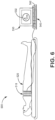
- Surrogate electrical activation information or data of one or more regions of a patient's heart may be monitored, or determined, using electrode apparatus 510 as shown in FIGS. 6-8 .
- the electrode apparatus 510 may be configured to measure body-surface potentials of a patient 520 and, more particularly, torso-surface potentials of the patient 520.
- the electrode apparatus 510 may include a set, or array, of electrodes 512, a strap 513, and interface/amplifier circuitry 516. A portion of the set of electrodes may be used wherein the portion corresponds to a particular location on the patient's heart.
- the electrodes 512 may be attached, or coupled, to the strap 513, and the strap 513 may be configured to be wrapped around the torso of a patient 520 such that the electrodes 512 surround the patient's heart.
- the electrodes 512 may be positioned around the circumference of a patient 520, including the posterior, lateral, posterolateral, anterolateral, and anterior locations of the torso of a patient 520.
- the electrodes 512 may be electrically connected to interface/amplifier circuitry 516 via wired connection 518.
- the interface/amplifier circuitry 516 may be configured to amplify the signals from the electrodes 512 and provide the signals to the computing apparatus 540.
- Other systems may use a wireless connection to transmit the signals sensed by electrodes 512 to the interface/amplifier circuitry 516 and, in turn, the computing apparatus 540, for example, as channels of data.
- the interface/amplifier circuitry 516 may be electrically coupled to each of the computing apparatus 540 and the display apparatus 530 using, for example, analog electrical connections, digital electrical connections, wireless connections, bus-based connections, network-based connections, internet-based connections, etc.
- the electrode apparatus 510 includes a strap 513
- any of a variety of mechanisms for example, tape or adhesives, may be employed to aid in the spacing and placement of electrodes 512.
- the strap 513 may include an elastic band, strip of tape, or cloth.
- the electrodes 512 may be placed individually on the torso of a patient 520. Further, in other examples, electrodes 512 (for example, arranged in an array) may be part of, or located within, patches, vests, or other manners of securing the electrodes 512 to the torso of the patient 520.
- the electrodes 512 may be configured to surround the heart of the patient 520 and record, or monitor, the electrical signals associated with the depolarization and repolarization of the heart after the signals have propagated through the torso of a patient 520. Each of the electrodes 512 may be used in a unipolar configuration to sense the torso-surface potentials that reflect the cardiac signals.
- the interface/amplifier circuitry 516 may also be coupled to a return or indifferent electrode (not shown) that may be used in combination with each electrode 512 for unipolar sensing. In some examples, there may be about 12 to about 50 electrodes 512 spatially distributed around the torso of the patient. Other configurations may have more or fewer electrodes 512.
- the computing apparatus 540 may record and analyze the electrical activity (for example, torso-surface potential signals) sensed by electrodes 512 and amplified/conditioned by the interface/amplifier circuitry 516.
- the computing apparatus 540 may be configured to analyze the signals from the electrodes 512 to provide as anterior and posterior electrode signals and surrogate cardiac electrical activation times, for example, representative of actual, or local, electrical activation times of one or more regions of the patient's heart as will be further described herein.
- the computing apparatus 540 may be configured to analyze the signals from the electrodes 512 to provide as anterior-septal electrode signals and surrogate cardiac electrical activation times, for example, representative of actual, or local, electrical activation times of one or more anterior-septal regions of the patient's heart, as will be further described herein, for example, for use in calibrating, delivering, or evaluating pacing therapy.
- the electrical signals measured at the left anterior surface location of a patient's torso may be representative, or surrogates, of electrical signals of the left anterior left ventricle region of the patient's heart
- electrical signals measured at the left lateral surface location of a patient's torso may be representative, or surrogates, of electrical signals of the left lateral left ventricle region of the patient's heart
- electrical signals measured at the left posterolateral surface location of a patient's torso may be representative, or surrogates, of electrical signals of the posterolateral left ventricle region of the patient's heart
- electrical signals measured at the posterior surface location of a patient's torso may be representative, or surrogates, of electrical signals of the posterior left ventricle region of the patient's heart.
- Measurement of activation times can be performed by measuring the period of time between an onset of cardiac depolarization (for example, onset of QRS complex) and an appropriate fiducial point such as, for example, a peak value, a minimum value, a minimum slope, a maximum slope, a zero crossing, a threshold crossing, etc.
- an onset of cardiac depolarization for example, onset of QRS complex
- an appropriate fiducial point such as, for example, a peak value, a minimum value, a minimum slope, a maximum slope, a zero crossing, a threshold crossing, etc.
- the computing apparatus 540 may be configured to provide graphical user interfaces depicting the surrogate electrical activation times obtained using the electrode apparatus 510.
- Systems, methods, or interfaces may noninvasively use the electrical information collected using the electrode apparatus 510 to evaluate a patient's cardiac condition or to calibrate, deliver, or evaluate cardiac pacing therapy to be or being delivered to the patient.
- FIG. 8 illustrates another electrode apparatus 510 that includes a plurality of electrodes 512 configured to surround the heart of the patient 520 and record, or monitor, the electrical signals associated with the depolarization and repolarization of the heart after the signals have propagated through the torso of the patient 520.
- the electrode apparatus 510 may include a vest 514 upon which the plurality of electrodes 512 may be attached, or to which the electrodes 512 may be coupled.
- the plurality, or array, of electrodes 512 may be used to collect electrical information such as, for example, surrogate electrical activation times.
- the electrode apparatus 510 of FIG. 8 may include interface/amplifier circuitry 516 electrically coupled to each of the electrodes 512 through a wired connection 518 and be configured to transmit signals from the electrodes 512 to computing apparatus 540.
- the electrodes 512 may be distributed over the torso of a patient 520, including, for example, the anterior, lateral, posterolateral, anterolateral, and posterior surfaces of the torso of the patient 520.
- the vest 514 may be formed of fabric with the electrodes 512 attached to the fabric.
- the vest 514 may be configured to maintain the position and spacing of electrodes 512 on the torso of the patient 520. Further, the vest 514 may be marked to assist in determining the location of the electrodes 512 on the surface of the torso of the patient 520.
- the vest 514 may include about 17 or more anterior electrodes positionable proximate the anterior torso of the patient, and about 39 or more posterior electrodes positionable proximate the posterior torso of the patient. In some examples, there may be about 25 electrodes 512 to about 256 electrodes 512 distributed around the torso of the patient 520, though other configurations may have more or fewer electrodes 512.
- Electrical activity may be monitored using a plurality of external electrodes, such as electrodes 512 of FIGS. 6-8 .
- the electrical activity can be monitored by a plurality of electrodes during pacing therapy or in the absence of pacing therapy.
- the monitored electrical activity can be used to evaluate pacing therapy to a patient.
- the electrical activity monitored using the ECG belt described can be used to evaluate at least one paced setting of the pacing therapy on the heart.
- a paced setting can be any one parameter or a combination of parameters including, but not limited to, electrode position, pacing polarity, pacing output, pacing pulse width, timing at which ventricular pacing is delivered relative to atrial timing, pacing rate, etc.
- the location of the leadless device or a pacing lead can include a location in the right ventricle, left ventricle, or right atrium.
- body-surface isochronal maps of ventricular activation can be constructed using the monitored electrical activity during pacing therapy or in the absence of pacing therapy.
- the monitored electrical activity or the map of ventricular activation can be used to generate electrical heterogeneity information (EHI).
- the electrical heterogeneity information can include determining metrics of electrical heterogeneity.
- the metrics of electrical heterogeneity can include a metric of standard deviation of activation times (SDAT) of electrodes on a left side of a torso of the patient or a metric of mean left ventricular activation time (LVAT) of electrodes on the left side of the torso of the patient.
- SDAT standard deviation of activation times
- LVAT mean left ventricular activation time
- a metric of LVAT may be determined from electrodes on both the anterior and posterior surfaces, which are more proximal to the left ventricle.
- the metrics of electrical heterogeneity information can include a metric of mean right ventricular activation time (RVAT) of electrodes on the right side of the torso of the patient.
- RVAT mean right ventricular activation time
- a metric of RVAT may be determined from electrodes on both the anterior and posterior surfaces which are more proximal to the right ventricle.
- the metrics of electrical heterogeneity can include a metric of mean total activation time (mTAT) taken from a plurality of electrode signals from both sides of the torso of the patient, or it may include other metrics (for example, standard deviation, interquartile deviations, a difference between a latest activation time and earliest activation time) reflecting a range or dispersion of activation times on a plurality of electrodes located on the right side of the patient torso or left side of the patient torso, or combining both right and left sides of the patient torso.
- the metrics of electrical heterogeneity information can include a metric of anterior-septal activation times (ASAT) of electrodes on the torso in close proximity to the anterior-septal portion of the heart.
- ASAT anterior-septal activation times
- Electrical heterogeneity information may be generated during delivery of pacing therapy at one or more paced settings.
- the electrical heterogeneity information can be generated using metrics of electrical heterogeneity.
- the metrics of electrical heterogeneity can include one or more of an SDAT, an LVAT, an RVAT, an mTAT, and an ASAT.
- only ASAT may be determined and further used, or ASAT may be more heavily weighted than other values.
- a paced setting can include a plurality of pacing parameters.
- the plurality of pacing parameters can be optimal if the patient's cardiac condition improves, if the pacing therapy is effectively capturing a desired portion of the RA, RV, or LV, or if a metric of electrical heterogeneity improves by a certain threshold compared to a baseline rhythm or therapy.
- the determination of whether the paced setting is optimal can be based on at least one metric of electrical heterogeneity generated from electrical activity during pacing (and also, in some cases, during native conduction, or in the absence of pacing).
- the at least one metric can include one or more of an SDAT, an LVAT, an RVAT, an mTAT, and an ASAT.
- the plurality of pacing parameters can be optimal if a metric of electrical heterogeneity is greater than or less than a particular threshold, or if the location of the pacing therapy to excite the left ventricle causes a particular pattern of excitation of the muscle fibers in the heart.
- the plurality of pacing parameters can be optimal if a metric of electrical heterogeneity indicates a correction of a left bundle branch block (LBBB), or if a metric of electrical heterogeneity indicates a complete engagement of a Purkinje system, etc.
- LBBB left bundle branch block
- a metric of electrical heterogeneity of an ASAT less than or equal to a threshold (for example, a threshold of 30 ms) and an LVAT less than or equal to a threshold (for example, a threshold of 30 ms) can indicate a correction of an LBBB, and thus, the paced setting is optimal.
- a metric of electrical heterogeneity of an RVAT less than or equal to a threshold (for example, a threshold of 30 ms), an ASAT less than or equal to a threshold (for example, a threshold of 30 ms), and an LVAT less than or equal to a threshold (for example, a threshold of 30 ms) can indicate a complete engagement of the Purkinje system, and thus the paced setting is may be optimal.
- the paced setting can be determined to be optimal in response to the pacing therapy using the paced setting being acceptable, being beneficial, being indicative of complete engagement of patient's native cardiac conduction system, being indicative of correction of a ventricular conduction disorder (for example, left bundle branch block), etc.
- a paced setting can include one or more of a pacing electrode position (including one or more of a depth, an angle, an amount of turn for a screw-based fixation mechanism, etc.), a voltage, a pulse width, an intensity, a pacing polarity, a pacing vector, a pacing waveform, a timing of the pacing delivered relative to an intrinsic or paced atrial event or relative to the intrinsic His bundle potential, or a pacing location, etc.
- a pacing vector can include any two or more pacing electrodes such as, for example, a tip electrode to a can electrode, a tip electrode to a ring electrode etc., that are used to deliver the pacing therapy, etc.
- the pacing location can refer to the location of any of the one or more pacing electrodes that are positioned using a lead, a leadless device, or any device or apparatus configured to deliver pacing therapy.
- a paced setting for therapy may be adjusted.
- the paced setting can be adjusted in response to the paced setting being not optimal.
- the paced setting can be adjusted in response to the paced setting being within an optimal range but in order to determine whether the paced setting can be at a position within the optimal range that is more beneficial, more useful, more functional, etc., for the pacing therapy.
- the paced setting could be adjusted to find the most optimal metric of electrical heterogeneity.
- a determination of whether the paced setting is optimal can be based on a particular metric of electrical heterogeneity using an ECG belt.
- the paced setting can be adjusted at intervals that correlate with a change in the metric of electrical heterogeneity until the metric of electrical heterogeneity is at or proximate a particular metric value.
- the adjusting of the paced setting can cause the metric of electrical heterogeneity to approach a particular threshold metric of electrical heterogeneity and, as the metric approaches the particular threshold, the rate at which the paced setting is adjusted can be slowed down.
- the paced setting can be adjusted more quickly and as the metric of electrical heterogeneity gets closer to the particular threshold metric, the paced setting can be adjusted more slowly until the metric of electrical heterogeneity is at the particular threshold metric.
- FIG. 9 is a flow diagram that illustrates one example of a method that may be used with the therapy modeling system 200 ( FIG. 4 ) to manage therapy, such as HFpEF therapy.
- the method 220 may include determining whether a patient has HFpEF 222.
- the HFpEF classification, or diagnosis may be made by the clinician in a clinical setting or may be determined from patient history data. In some embodiments, other conditions may be tested 236, for example, in response to determining that the patient does not have HFpEF 222.
- the method 220 may continue to manage HFpEF therapy, for example, in response to determining that the patient has HFpEF 222.
- a patient characterization may be determined based on patient characterization 224, for example, in response to determining that the patient has HFpEF 222.
- the patient characterization data 224 may be based on one or more of the following: clinician input data, electrode apparatus data, echocardiogram data, imaging data, patient history data, hemodynamic measurement data, or IMD data.
- a CV model of the therapy modeling system 200 may be configured to represent the patient based on the patient characterization 226, for example, in response to determining the patient characterization 224.
- Any suitable CV model that appropriately characterizes a patient's heart and cardiovascular structure for HF, or specifically HFpEF, may be used.
- Non-limiting example of CV models include the CircAdapt model (available from Maastricht University of Maastricht, Netherlands), the HARVI model (available from PVLoops LLC of New York, New York), and the CARP model (available from Medical University Graz of Graz, Austria).
- the CV model may be configured using some or all the patient characterization data described herein and provide output data.
- the output data may include various parameters representing a simulated response of the patient's heart.
- One or more therapy parameters may be determined based on output data from the CV model 228, for example, in response to configuring the CV model 226.
- Therapy parameters may include a type of therapy or particular parameters used to configure a particular therapy.
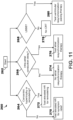
- determining a type of therapy may include determining one or more candidate therapies using the CV model (see FIG. 10 ).
- determining a type of therapy may include determining a non-pacing therapy by a clinician using the CV model (see FIG. 15 ).
- therapy parameters may be determined for pacing therapy, such as a type of pacing therapy (such as cardiac remodeling pacing therapy, atrial resynchronization therapy, cardiac resynchronization therapy, or ventricular resynchronization therapy), a pacing rate, a sensing or pacing location, a pacing duration, a pacing duty cycle, or a pacing frequency.
- Pacing therapy may be administered using an IMD, such as IMD 16 ( FIG. 1 ).
- a sensing or pacing location may be indicative of an atrial location, a ventricular location, or a conduction system or His bundle location.
- a pacing duration, duty cycle, and frequency may be used together to indicate, for example, five hours of continuous pacing daily, intermittent with 10 minute duration and 20 minute duty cycle.
- administering therapy may include configuring an IMD and administering pacing therapy using the IMD. Additionally, or alternatively, in some embodiments, administering therapy may include administering non-pacing therapy by a clinician. For example, in some embodiments, administering the non-pacing therapy may include providing the one or more therapy parameters for non-pacing therapy to the clinician on a user interface device. The clinician may provide the non-pacing therapy to the patient, such as a surgical procedure.
- the CV model may be updated, for example, based on the patient's response 232, for example, in response to administering therapy 230.
- patient response data may be provided, for example, from the clinician or from the IMD, as patient characterization data to the therapy modeling system 200.
- the model may be reconfigured based on the patient response data, which may also be described as updated patient characterization data.
- the therapy modeling system 200 may be described as providing continuous therapy optimization using model predictions based on changes (reinforcement learning techniques).
- the CV model may be updated based on a predicted patient characterization value and a measured patient characterization value after administering HFpEF therapy.
- the predicted patient characterization value may be generated based on the output data of the CV model.
- the patient characterization system 150 ( FIG. 4 ) or the therapy delivery system 10 ( FIG. 4 ) may be used to measure a patient characterization value after administering HFpEF therapy, for example, after a period of time.
- the predicted and measured patient characterization values may be compared and used as feedback to update the CV model to facilitate future predictive accuracy.
- the therapy may be updated based on output data 234 from the updated (or reconfigured) CV model, for example, in response to updating the CV model 232.
- the therapy may be updated in a clinical setting or updated remotely, for example, over an internet connection between the IMD of the therapy delivery system and the therapy modeling system 200.
- the CV model or the therapy may be updated over the internet.
- Patient response data may be determined based on updated patient characterization data, for example, measured using an implantable medical device (IMD).
- IMD implantable medical device
- the updated patient characterization data may be provided over the internet to a remote therapy modeling system 200.
- the CV model may be executed by processing circuitry of the remote therapy modeling system 200.
- the therapy modeling system 200 may be described as providing ambulatory updates over the internet. Updates from the therapy delivery system 10 may be used as feedback to the CV model to drive continuous optimization. For example, an impedance change indicating an expansion of the ventricular volume may reach or exceed a corresponding threshold.
- the therapy delivery system 10 may trigger a transmission, or periodically send a transmission, to the therapy modeling system 200, and the CV model may be automatically updated and run by the therapy management system.
- a recommendation, or an automated update may be made regarding the pacing rate to preserve a target cardiac volume without additional expansion, which may be provided by the therapy modeling system 200 to the clinician interface system 130 ( FIG. 4 ) or the therapy delivery system 10.
- the method 220 may include determining a characterization by classification of a patient, such as a cohort or micro-cohort for the particular patient.
- the cohort or micro-cohort may be determined, for example, based in physician input from a clinical exam or from patient history data. Individual patient data may or may not be used in addition to the classification.
- the CV model may be configured based on the particular patient cohort or micro-cohort.
- One or more candidate therapies may be determined, or tested, using the CV model (see FIG. 10 ).
- pacing therapy by an IMD may be tested with one or more test therapy parameters using the CV model to provide output data indicating a simulated patient response.
- the candidate therapies may include any suitable therapy, such as HFpEF therapy, or enabling therapy. Enabling therapy may be described as therapy that enables effective treatment using another therapy (see FIG. 17 ).
- One or more therapy parameters which may include a selected therapy, may be determined based on the output data from the CV model. The one or more therapy parameters may also be determined based on clinician input, for example, to configure the CV model, to run tests using the CV model, or after receiving output data from the CV model.
- An IMD may be selected and configured based on the one or more therapy parameters, and the configured IMD may be used to administer pacing therapy.
- FIG. 10 is a flow diagram that illustrates one example of a method 240 for determining one or more candidate therapies using the CV model, which may be used, for example, in configuring the CV model 226 ( FIG. 6 ) and determining the one or more therapy parameters 228 ( FIG. 6 ).
- the method 240 may include determining whether the patient has atrial fibrillation (AF) 242.
- An AF classification may be determined based on patient characterization data, such as electrode apparatus data from an ECG, ECG belt, or ECG vest or patient history data indicating AF.
- the AF classification may be used to configure the CV model.
- An atrioventricular (AV) delay for pacing therapy may be optimized 246, for example, in response to determining that the patient does not have AF 242. Any suitable technique may be used to optimize AV delay (for example, see FIG. 11 ). In general, optimizing the AV delay may include testing a plurality of different pacing therapies to identify acceptable AV delays using the CV model.
- the CV model may be configured for a patient having HFpEF without AF. Optimizing the AV delay may be used to determine one or more therapy parameters.
- Determining whether the patient has a left bundle branch block (LBBB) 248 may be determined, for example, in response to determining that the patient has AF 242.
- An LBBB classification may be determined based on patient characterization data, such as electrode apparatus data from an ECG, ECG belt, or ECG vest or patient history data indicating an LBBB. The LBBB classification may be used to configure the CV model.
- Ventricular resynchronization pacing therapy may be tested 250, for example, in response to determining that the patient has an LBBB 248. Any suitable technique may be used to test ventricular resynchronization pacing therapy (for example, see FIG. 12 ).
- the CV model may be configured for a patient having AF and an LBBB. Testing ventricular resynchronization pacing therapy may be used to determine one or more therapy parameters.
- One or more therapy parameters may be determined to not provide CRT 252, for example, in response to determining that the patient does not have an LBBB 248.
- other therapies such as RBBB pacing therapy or non-specific intraventricular delay pacing therapy, may be provided.
- FIG. 11 is a flow diagram that illustrates one example of a method 260 for testing a plurality of different pacing therapies to identify acceptable AV delays using the CV model, which may be used in optimizing the AV delay 246 ( FIG. 10 ).
- the method 260 may start 262 by determining one or more classifications of the patient, such as one or more of determining whether the patient has concentric hypertrophy or concentric remodeling 264, determining whether the patient has an intra-atrial conduction delay 266, or determining whether the patient has an LBBB 268.
- the CV model may be configured before testing in the method 260 to represent a patient that has HFpEF and does not have AF.
- Whether the patient has concentric hypertrophy or concentric remodeling 264 may be determined, for example, using echocardiogram data or other imaging data.
- the CV model may be further configured based on whether the patient has concentric hypertrophy or concentric remodeling.
- the method 260 may include testing an elevated HR pacing therapy for symptom relief 270, for example, in response to determining that the patient does not have concentric hypertrophy or concentric remodeling 264.
- the CV model may be further configured before testing to represent a patient that does not have concentric hypertrophy or concentric remodeling.
- the method 260 may include testing an elevated HR pacing therapy for remodeling 272, for example, in response to determining that the patient has concentric hypertrophy or concentric remodeling 264.
- the CV model may be further configured before testing to represent a patient that has concentric hypertrophy or concentric remodeling.
- the elevated HR pacing therapy for remodeling may include one or more HR pacing rates that are higher than the elevated HR pacing therapy for symptom relief.
- the elevated HR pacing therapy for symptom relief may be described as a "mild” elevated, or increased, HR pacing therapy, which is intended to not to lead to remodeling.
- the elevated pacing therapy for remodeling may be described as an "aggressive" elevated, or increased, HR pacing therapy, which may be intended to lead to remodeling.
- Whether the patient has an intra-atrial conduction delay 266 may be determined, for example, based on electrode apparatus data from an ECG, ECG belt, or ECG vest.
- the CV model may be further configured based on whether the patient has an intra-atrial conduction delay.
- the method 260 may include determining one or more therapy parameters to provide no atrial resynchronization therapy 274 or determining to not test atrial resynchronization therapy, for example, in response to determining that the patient does not have an intra-atrial conduction delay 266.
- the method 260 may include testing atrial resynchronization therapy 276, for example, in response to determining that the patient has an intra-atrial conduction delay 266.
- the CV model may be further configured before testing to represent a patient that has an intra-atrial conduction delay.
- Testing an intra-atrial conduction delay 276 may include one or more of the following: testing Bachmann's bundle pacing, testing biatrial pacing (RA-LA pacing), or testing left atrial fusion pacing (LA pacing triggered by right atrial sensing).
- Whether the patient has an LBBB 268 may be determined, for example, using electrode apparatus data from an ECG, ECG belt, or ECG vest.
- the CV model may be further configured based on whether the patient has an LBBB.
- the method 260 may include determining one or more therapy parameters to not provide CRT 278 or determining not to test ventricular resynchronization pacing therapy, for example, in response to determining that the patient does not have an LBBB 268.
- the method 260 may include testing ventricular resynchronization pacing therapy 280, for example, in response to determining that the patient has an LBBB 268.
- the CV model may be further configured before testing to represent a patient that has an LBBB.
- Testing ventricular resynchronization pacing therapy 280 may include one or more of the following: testing left bundle branch (LBB) pacing, testing His bundle pacing, testing left ventricular pacing (such as LV myocardial pacing, or testing bi-ventricular pacing.
- LBB left bundle branch
- His bundle pacing testing left ventricular pacing (such as LV myocardial pacing, or testing bi-ventricular pacing.
- one of the pacing therapies having acceptable AV delays may be selected.
- acceptable AV delays may be determined using a range of acceptable AV delay thresholds. Any suitable technique may be used to determine an acceptable AV delay known to one skilled in the art having the benefit of this disclosure.
- FIG. 12 is a flow diagram that illustrates one example of a method 300 for testing ventricular resynchronization pacing therapy, which may be used in test 250 ( FIG. 10 ) or in test 280 to optimize the AV delay 260 ( FIG. 11 ).
- the method 300 may include determining a plurality of cardiac dyssynchrony measure values using the CV model 302. Each measure value may correspond to a different test ventricular resynchronization therapy of a plurality of test ventricular resynchronization pacing therapies.
- One example of a cardiac dyssynchrony measure is SDAT.
- an SDAT may be determined for each CRT, such as ventricular resynchronization pacing therapy, being tested.
- the method 300 may include determining whether any of the cardiac dyssynchrony measure values indicate a reduction from a baseline patient cardiac dyssynchrony measure value greater than or equal to a reduction threshold 304.
- reduction thresholds include 5, 10, 15, or 20 percent.
- a reduction threshold of 10 percent may be used.
- the reduction threshold may be determined based on SDAT measure values.
- the method 300 may also include determining (or selecting) to provide one or more therapy parameters to provide no ventricular resynchronization pacing therapy 306, for example, in response to determining that none of the cardiac dyssynchrony measure values indicate a reduction of greater than the reduction threshold 304.
- the method 300 may include determining a largest reduction cardiac dyssynchrony measure value corresponding to a largest reduction in cardiac dyssynchrony from the baseline patient cardiac dyssynchrony measure value, for example, in response to determining that at least one of the cardiac dyssynchrony measure values indicates a reduction greater than or equal to the reduction threshold 304.
- the method 300 may also include determining whether the largest reduction cardiac dyssynchrony measure value is greater than the other cardiac dyssynchrony measure values by at least a comparative threshold 308.
- comparative thresholds include 1, 2, 3, 4, 5, 6, 7, 8, 9, or 10 basis points of the particular cardiac dyssynchrony measure, such as SDAT. In some embodiments, a comparative threshold of 5 basis points for SDAT may be used.
- the method 300 may also include determining (or selecting) one or more therapy parameters to provide ventricular resynchronization pacing therapy corresponding to the largest reduction cardiac dyssynchrony measure value 310, for example, in response to determining that that the largest reduction cardiac dyssynchrony measure value is greater than the other cardiac dyssynchrony measure values by at least the comparative threshold 308.
- the one or more therapy parameters for ventricular resynchronization pacing therapy may be determined based on the largest SDAT reduction.
- the method 300 may include evaluating one or more other patient characterization parameters 312, for example, in response to determining that the largest reduction cardiac dyssynchrony measure value is not greater than the other cardiac dyssynchrony measure values by at least the comparative threshold 308.
- FIG. 13 is a flow diagram that illustrates one example of a method 320 for evaluating one or more other patient characterization parameters, which may be used in evaluation 312 ( FIG. 12 ). In some embodiments, the method 320 may be used to determine one or more therapy parameters 228 ( FIG. 9 ) .
- the method 320 may include discarding any cardiac dyssynchrony measure values not within range of the largest reduction cardiac dyssynchrony measure value by the comparative threshold 314, for example, in response to determining that the largest reduction cardiac dyssynchrony measure value is not greater than the other cardiac dyssynchrony measure values by at least the comparative threshold 308 ( FIG. 12 ) .
- the method 320 may also include determining which of the cardiac dyssynchrony measure values correspond to a maximum LV stroke work using the CV model 316, for example, in response to discarding any cardiac dyssynchrony measure values not within range of the largest reduction cardiac dyssynchrony measure value by the comparative threshold 314.
- a maximum cardiac stroke work efficiency may be used in addition to, or as an alternative to, the maximum LV stroke work.
- the method 320 may include determining (or selecting) the one or more therapy parameters to provide ventricular resynchronization pacing therapy based on the cardiac dyssynchrony measure value corresponding to the maximum LV stroke work 318, for example, in response to determining which of the cardiac dyssynchrony measure values correspond to a maximum LV stroke work using the CV model 316.
- FIG. 14 is a diagram that illustrates one example of a plot 340 of output data from a CV model, which may be used to determine one or more therapy parameters 228 ( FIG. 9 ).
- the plot 340 may be used to predict a patient response to therapy and to evaluate whether certain therapy parameters should be avoided, which may be described as therapy optimization.
- the plot 340 is based on patient-specific characterization data. In other embodiments, a best-match patient CV model or classification-based CV model may be used.
- a clinician or the therapy modeling system 200 may determine to test a therapy to elevate the heart rate above normal while avoiding over-taxing the heart (see test 270 and test 272 of FIG. 11 ).
- Patient characterization data such as echocardiogram data and hemodynamic measurement data, may be used to configure the CV model.
- the output data of the CV model may provide a simulated cardiac stroke work efficiency (normalized to baseline) versus heartrate (per minute) over a range of pacing rates from about 70 to about 150 HBPM.
- the plot 340 shows two different sets of responses from CV models that were configured using two different sets of patient characterization data.
- the first data set 342 (illustrated with white diamonds) shows a maximum efficiency at about 100 HBPM.
- the second data set 344 (illustrated with black diamonds) shows a maximum efficiency around 125 HBPM.
- the therapy modeling system 200 may determine one or more therapy parameters (for example, for an IMD) to provide HR pacing at the corresponding maximum efficiency.
- a visualization of the plot 340 may also be provided to the clinician.
- determining one or more therapy parameters may include determining a plurality of cardiac stroke work efficiencies each corresponding to a different pacing heart rate from a plurality of pacing heart rates using the CV model.
- the one or more therapy parameters may be determined to provide HFpEF therapy using a pacing heart rate corresponding to a maximum cardiac stroke work efficiency of the plurality of cardiac stroke work efficiencies.
- FIG. 15 is a diagram that illustrates one example of a plot 360 of output data from a CV model, for example, as part of configuring the CV model 226 ( FIG. 9 ) and determining one or more therapy parameters 228 ( FIG. 9 ).
- the plot 360 may be used to predict a patient response to candidate therapies and to evaluate whether certain therapies should be avoided, which may be described as therapy selection.
- a clinician or the therapy modeling system 200 may determine to test non-pacing interventions as possible candidate therapies.
- the interventions may be evaluated for ability to lower cardiac filling pressure (such as a left-ventricular end-diastolic pressure, or LVEDP).
- cardiac filling pressure such as a left-ventricular end-diastolic pressure, or LVEDP.
- Patient characterization data such as imaging data (MRI or CT scan of the thorax) and hemodynamic measurement data (LV pressure), may be used to configure the CV model.
- the CV model may include the heart and circulatory system including the pericardium.
- the CV model may be a finite-element model.
- the output data of the CV model may provide a simulated LVEDP (mmHg) versus end diastolic volume (mm) over a range of end diastolic volumes, such as 50 to 200 mm.
- the plot 360 shows five different sets of responses from CV models that were configured to simulate different types of therapies.
- the plot 360 shows LVEDP values based on different CV models configured to represent a baseline LVEDP (no intervention) 362, a pericardial resection intervention 364, an interatrial shunting intervention 366, a trabecular cutting intervention 368, and a target LVEDP 370.
- the plot 360 may be used to select the therapy or intervention that is closest to the target LVEDP 370.
- heuristic for selection is the smallest total sum of differences between a particular therapy and the target LVEDP 370.
- the trabecular cutting intervention 368 may be recommended over the other interventions.
- the therapy modeling system 200 may determine the appropriate intervention as a therapy parameter and may communicate the therapy parameter to the clinician (for example, using the clinician interface system 130 of FIG. 4 ).
- a visualization of the plot 360 may also be provided to the clinician.
- testing non-pacing therapies includes using the CV model to provide output data including left ventricular end diastolic pressure (LVEDP) for various end diastolic volumes.
- testing non-pacing therapy includes comparing non-pacing therapies to a target patient function, such as a target LVEDP versus end diastolic volume.
- FIG. 16 is a diagram that illustrates one example of a plot 380 of output data from a CV model, example, as part of configuring the CV model 226 ( FIG. 9 ) and determining one or more therapy parameters 228 ( FIG. 9 ).
- the plot 380 may be used to predict a patient response to a therapy over time and to configure the therapy based on the prediction, which may be described as therapy titration.
- a clinician or the therapy modeling system 200 may determine to test the patient response to a particular therapy over time.
- the CV model may be used to update or guide the application of the therapy based on the predicted patient response.
- the output data of the CV model may be used to update the CV model based on patient response to facilitate targeting of a changing new optimal therapy or to determine whether certain therapies should be avoided.
- testing the patient response to therapy over time may be used where rapid HR pacing is used for periods of time to increase the volume of the heart.
- Patient characterization data such as echocardiogram data and hemodynamic measurement data may be used to configure the CV model.
- the CV model may include at least the circulatory system.
- the output data of the CV model may provide a simulated left ventricular end diastolic diameter (LVEDD) (mm) versus pacing rate (HBPM) over a range of pacing rates, such as 90 to 140.
- the output data of the CV model may provide a predicted LVEDD after a period of time after administering the therapy.
- the plot 380 represents the predicted LVEDD 382 over various pacing rates after 3 months of administering the therapy.
- the CV model may be used to sweep the different rate and durations to simulate the potential patient response.
- the therapy modeling system 200 may determine or adjust the target intervention heart rate based on the patient response indicated by the CV model. In the illustrated embodiment, the therapy modeling system 200 may select a pacing rate of 125 HBPM so that 47 mm LVEDD will occur around next follow-up visit in the clinic at 3 months.
- the therapy modeling system 200 may updating the CV model based on patient response data after administering HFpEF therapy and may update the HFpEF therapy based on the updated CV model.
- the CV model may be updated at the next clinic visit.
- the therapy administration may start using a nominal or patient classification-based pacing rate based on a starting LVEDD 384.
- the therapy administration may start using the optimized pacing rate determined using the CV model.
- the CV model may be updated after updating patient characterization data.
- the target LVEDD may be reevaluated (for example, changed from 47 mm), and the pacing rate may be updated accordingly using the updated CV model to achieve the new target LVEDD.
- determining one or more therapy parameters may include determining a plurality of predicted patient characterization values each corresponding to a different therapy parameter value of a plurality of therapy parameter values using the CV model.
- Each predicted patient characterization value may indicate a predicted patient characterization value after administering HFpEF therapy using the corresponding therapy parameter value over a selected period of time based on the CV model.
- a target therapy parameter value may be determined from the different therapy parameter values based on a target patient characterization parameter and the plurality of predicted patient characterization values.
- the one or more therapy parameters may be determined to provide HFpEF therapy using the target therapy parameter value.
- FIG. 17 is a diagram that illustrates one example of a plot 400 of output data from a CV model, example, as part of configuring the CV model 226 ( FIG. 9 ) and determining one or more therapy parameters 228 ( FIG. 9 ).
- the plot 400 may be used to identify or determine an enabling therapy for another therapy, which may be described as therapy sequencing.
- a clinician or the therapy modeling system 200 may determine to guide two or more therapies, which may include an enabling therapy.
- the clinician or therapy modeling system 200 may determine whether a particular therapy is effective.
- the therapy modeling system 200 may determine whether an enabling therapy may be used to initiate a patient response that may enable the particular patient therapy using the CV model.
- the enabling therapy may be administered, and the patient characterization data may be updated, until the patient characterization data indicates that the particular therapy may be successful.
- the therapy modeling system 200 may identify a factor that may keep a particular therapy from working until the factor is addressed and may identify one or more therapy parameters for an enabling therapy.
- a factor that may keep a particular therapy from working until the factor is addressed and may identify one or more therapy parameters for an enabling therapy.
- an obese patient may have fat deposits on the heart.
- the CV model may be used to determine which patient parameters can be changed to allow dilation therapy, or HFpEF therapy with increased HR pacing, to work.
- Patient characterization data such as imaging data (MRI or CT scan) may be used to configure the CV model.
- the CV model may include the heart and circulatory system including the pericardium.
- the CV model may be a finite-element model.
- the output data of the CV model provide cardiac output (CO) or cardiac index (CI) versus modeled epicardial fat thickness (mm) over a range of thicknesses, such as 4 to 12 mm.
- the epicardial fat deposit size in the CV model may be varied to determine an intervention's effectiveness under different epicardial fat scenarios.
- the plot 400 shows two different sets of responses from CV models that were configured to simulate different types of therapies.
- the plot 400 shows CI values based on different CV models configured to represent HFpEF pacing therapy 402 and pericardial resection therapy 404.
- the therapy modeling system 200 may determine to provide an enabling therapy, such as determining to administer an SGLT2 inhibitor drug.
- the enabling therapy may be administered by the clinician or a therapy delivery system.
- the patient characterization data may be monitored or updated until epicardial fat reduction is obtained.
- the CV model may be updated based on the updated patient characterization data to help determine when conditions are met to allow one or both of the particular therapies 402, 404 to be effective in increasing CI (for example, above 6).
- administration of enabling therapy may be stopped and one or the particular therapies 402, 404 may be selected, for example, using therapy selection techniques described herein.
- determining one or more therapy parameters may include determining one or more enabling therapies using the CV model.
- Modified patient characterization data may be provided to the CV model (such as modified epicardial fat thicknesses). Whether the modified patient characterization data enables HFpEF therapy is determined (such as epicardial fat thickness below 5 or 6 mm).
- One or more enabling therapies may be selected based on the modified patient characterization data in response to determining that the modified patient characterization data enables HFpEF therapy.
- model-based therapy parameters for heart failure are disclosed. It should be understood that various aspects disclosed herein may be combined in different combinations than the combinations specifically presented in the description and accompanying drawings. It should also be understood that, depending on the example, certain acts or events of any of the processes or methods described herein may be performed in a different sequence, may be added, merged, or left out altogether (for example, all described acts or events may not be necessary to carry out the techniques). In addition, while certain aspects of this disclosure are described as being performed by a single module or unit for purposes of clarity, it should be understood that the techniques of this disclosure may be performed by a combination of units or modules associated with, for example, a medical device.
- the described techniques may be implemented in hardware, software, firmware, or any combination thereof. If implemented in software, the functions may be stored as one or more instructions or code on a computer-readable medium and executed by a hardware-based processing unit.
- Computer-readable media may include non-transitory computer-readable media, which corresponds to a tangible medium such as data storage media (for example, RAM, ROM, EEPROM, flash memory, or any other medium that can be used to store desired program code in the form of instructions or data structures and that can be accessed by a computer).
- processors such as one or more digital signal processors (DSPs), general purpose microprocessors, application specific integrated circuits (ASICs), field programmable logic arrays (FPGAs), or other equivalent integrated or discrete logic circuitry.
- DSPs digital signal processors
- ASICs application specific integrated circuits
- FPGAs field programmable logic arrays
- processors may refer to any of the foregoing structure or any other physical structure suitable for implementation of the described techniques. Also, the techniques could be fully implemented in one or more circuits or logic elements.
Landscapes
- Health & Medical Sciences (AREA)
- Life Sciences & Earth Sciences (AREA)
- Cardiology (AREA)
- Engineering & Computer Science (AREA)
- Heart & Thoracic Surgery (AREA)
- Public Health (AREA)
- General Health & Medical Sciences (AREA)
- Biomedical Technology (AREA)
- Veterinary Medicine (AREA)
- Animal Behavior & Ethology (AREA)
- Biophysics (AREA)
- Physics & Mathematics (AREA)
- Surgery (AREA)
- Molecular Biology (AREA)
- Medical Informatics (AREA)
- Pathology (AREA)
- Physiology (AREA)
- Nuclear Medicine, Radiotherapy & Molecular Imaging (AREA)
- Radiology & Medical Imaging (AREA)
- Artificial Intelligence (AREA)
- Computer Vision & Pattern Recognition (AREA)
- Psychiatry (AREA)
- Signal Processing (AREA)
- Hospice & Palliative Care (AREA)
- Electrotherapy Devices (AREA)
Claims (12)
- System, umfassend:eine Eingabeschnittstelle (204), die zum Empfangen von Patientencharakterisierungsdaten konfiguriert ist;eine Ausgabeschnittstelle (206), die zum Bereitstellen von Parameterdaten konfiguriert ist; undeine Verarbeitungsschaltung (208), die betriebsmäßig mit der Eingabeschnittstelle und der Ausgabeschnittstelle gekoppelt ist, wobei die Verarbeitungsschaltung konfiguriert ist zum:Empfangen der Patientencharakterisierungsdaten als Reaktion auf ein Bestimmen, dass ein Patient an einer Herzinsuffizienz mit erhaltener Ejektionsfraktion (HFpEF) leidet;Konfigurieren eines kardiovaskulären Modells (CV-Modells) unter Verwendung der Patientencharakterisierungsdaten;Bestimmen eines oder mehrerer Parameter unter Verwendung von Ausgabedaten des CV-Modells. undBereitstellen von Parameterdaten, die den einen oder die mehreren Parameter umfassen, an die Ausgabeschnittstelle.
- System nach Anspruch 1, das ferner eine implantierbare medizinische Vorrichtung (IMD) (16) umfasst, die so konfiguriert ist, dass sie unter Verwendung des CV-Modells die Stimulation testet, um den einen oder die mehreren Parameter zu bestimmen.
- System nach Anspruch 2, wobei das IMD so konfiguriert ist, dass es die Parameterdaten empfängt, und der eine oder die mehreren Parameter einen oder mehrere der folgenden Parameter umfassen: eine Art der Stimulation, eine Stimulationsrate, eine Abtast- oder Stimulationsstelle, eine Stimulationsdauer, ein Stimulationstastverhältnis oder eine Stimulationsfrequenz.
- System nach einem der vorhergehenden Ansprüche, wobei die Patientencharakterisierungsdaten zum Konfigurieren des CV-Modells auf einem oder mehreren der folgenden beruhen: Eingabedaten des Klinikers, Elektrodengerätedaten, Echokardiogrammdaten, Bildgebungsdaten, Patientenhistoriendaten, hämodynamische Messdaten oder Daten von implantierbaren medizinischen Vorrichtungen (IMD).
- System nach einem der vorhergehenden Ansprüche, wobei das CV-Modell unter Verwendung von Patientencharakterisierungsdaten konfiguriert wird, die angeben, ob der Patient an Vorhofflimmern (AF) leidet.
- System nach einem der vorhergehenden Ansprüche, wobei das CV-Modell unter Verwendung von Patientencharakterisierungsdaten konfiguriert wird, die angeben, ob der Patient an konzentrischer Hypertrophie oder konzentrischem Remodeling leidet.
- System nach einem der vorhergehenden Ansprüche, wobei das CV-Modell unter Verwendung von Patientencharakterisierungsdaten konfiguriert wird, die angeben, ob der Patient an einer intraatrialen Leitungsverzögerung leidet.
- System nach einem der vorhergehenden Ansprüche, wobei der Verarbeitungsschaltkreis so konfiguriert ist, dass er einen oder mehrere Parameter unter Verwendung von Ausgabedaten des CV-Modells bestimmt, indem er eine ventrikuläre Resynchronisationsstimulation unter Verwendung des CV-Modells in Reaktion auf die Patientencharakterisierungsdaten testet, die angeben, dass der Patient an einem Linksschenkelblock (LBBB) leidet.
- System nach einem der vorhergehenden Ansprüche, wobei die Verarbeitungsschaltung einen oder mehrere Parameter unter Verwendung von Ausgabedaten des CV-Modells bestimmt, indem sie ferner konfiguriert ist zum:Bestimmen einer Vielzahl von Messwerten der kardialen Dyssynchronie unter Verwendung des CV-Modells, wobei jeder Messwert einer unterschiedlichen Test-Ventrikel-Resynchronisationstherapie entspricht,Bestimmen, ob einer der Messwerte für die kardiale Dyssynchronie eine Reduktion von einem Baseline-Messwert der kardialen Dyssynchronie des Patienten angibt, die größer als oder gleich einem Reduktionsschwellenwert ist;als Reaktion auf das Bestimmen, dass keiner der Messwerte für die kardiale Dyssynchronie eine Reduktion von mehr als oder gleich dem Reduktionsschwellenwert angibt, Bestimmen des einen oder der mehreren Parameter, die keine ventrikuläre Resynchronisations-Stimulationstherapie vorsehen;als Reaktion auf das Bestimmen, dass mindestens einer der Messwerte der kardialen Dyssynchronie eine Reduktion angibt, die größer als oder gleich dem Reduktionsschwellenwert ist,Bestimmen eines Messwerts für die größte Reduktion der kardialen Dyssynchronie, der einer größten Reduktion der kardialen Dyssynchronie gegenüber dem Baseline-Messwert der kardialen Dyssynchronie des Patienten entspricht, undBestimmen, ob der Messwert für die größte Reduktion der Herzdyssynchronie um mindestens einen Vergleichsschwellenwert größer ist als die anderen Messwerte für die Herzdyssynchronie; undals Reaktion auf das Bestimmen, dass der Messwert für die größte Reduktion der kardialen Dyssynchronie um mindestens den Vergleichsschwellenwert größer ist als die anderen Messwerte für die kardiale Dyssynchronie, Bestimmen des einen oder der mehreren Parameter, die eine ventrikuläre Resynchronisations-Stimulationstherapie entsprechend dem Messwert für die größte Reduktion der kardialen Dyssynchronie bereitstellen.
- System nach Anspruch 9, wobei die Verarbeitungsschaltung einen oder mehrere Parameter unter Verwendung von Ausgabedaten des CV-Modells bestimmt, indem sie ferner konfiguriert ist zum:als Reaktion auf das Bestimmen, dass der Messwert für die größte Reduktion der Herzdyssynchronie nicht größer ist als die anderen Messwerte für die Herzdyssynchronie um mindestens den Vergleichsschwellenwert, alle Messwerte für die Herzdyssynchronie zu verwerfen, die nicht im Bereich des Messwerts für die größte Reduktion der Herzdyssynchronie um den Vergleichsschwellenwert liegen;Bestimmen, unter Verwendung des CV-Modells, welche der Herzdyssynchronie-Messwerte einer maximalen LV-Schlagarbeit entsprechen; undBestimmen des einen oder der mehreren Parameter, die eine ventrikuläre Resynchronisations-Stimulationstherapie bereitstellen, basierend auf dem kardialen Dyssynchronie-Messwert, der der maximalen LV-Schlagarbeit entspricht.
- System nach einem der vorhergehenden Ansprüche, wobei die Verarbeitungsschaltung einen oder mehrere Parameter unter Verwendung von Ausgabedaten des CV-Modells bestimmt, indem sie ferner konfiguriert ist zum:Bestimmen einer Vielzahl von Herzschlagarbeitseffizienzen, die jeweils einer unterschiedlichen Schrittmacherherzfrequenz entsprechen, aus einer Vielzahl von Schrittmacherherzfrequenzen unter Verwendung des CV-Modells; undBestimmen des einen oder der mehreren Parameter, die eine HFpEF-Therapie bereitstellen, unter Verwendung einer Stimulationsherzfrequenz, die einer maximalen Herzschlagarbeitseffizienz aus der Vielzahl von Herzschlagarbeitseffizienzen entspricht.
- System nach einem der vorhergehenden Ansprüche, wobei die Verarbeitungsschaltung einen oder mehrere Parameter unter Verwendung von Ausgabedaten des CV-Modells bestimmt, indem sie ferner konfiguriert ist zum:Bestimmen einer Vielzahl von vorhergesagten Patientencharakterisierungswerten, die jeweils einem anderen Parameterwert einer Vielzahl von Parameterwerten entsprechen, unter Verwendung des CV-Modells, wobei jeder vorhergesagte Patientencharakterisierungswert einen vorhergesagten Patientencharakterisierungswert nach Verabreichung einer HFpEF-Therapie unter Verwendung des entsprechenden Parameterwertes über einen ausgewählten Zeitraum basierend auf dem CV-Modell angibt;Bestimmen eines Zielparameterwerts aus den verschiedenen Parameterwerten basierend auf einem Zielpatientencharakterisierungsparameter und der Vielzahl von vorhergesagten Patientencharakterisierungswerten; undBestimmen des einen oder der mehreren Parameter, die eine HFpEF-Therapie bereitstellen, unter Verwendung des Zielparameterwertes.
Applications Claiming Priority (3)
| Application Number | Priority Date | Filing Date | Title |
|---|---|---|---|
| US201962955625P | 2019-12-31 | 2019-12-31 | |
| US17/120,429 US11642032B2 (en) | 2019-12-31 | 2020-12-14 | Model-based therapy parameters for heart failure |
| PCT/US2020/065028 WO2021138041A1 (en) | 2019-12-31 | 2020-12-15 | Model-based therapy parameters for heart failure |
Publications (3)
| Publication Number | Publication Date |
|---|---|
| EP4084677A1 EP4084677A1 (de) | 2022-11-09 |
| EP4084677A4 EP4084677A4 (de) | 2024-01-17 |
| EP4084677B1 true EP4084677B1 (de) | 2025-01-29 |
Family
ID=76546881
Family Applications (1)
| Application Number | Title | Priority Date | Filing Date |
|---|---|---|---|
| EP20910361.3A Active EP4084677B1 (de) | 2019-12-31 | 2020-12-15 | Modellbasierte therapieparameter für herzversagen |
Country Status (4)
| Country | Link |
|---|---|
| US (1) | US11642032B2 (de) |
| EP (1) | EP4084677B1 (de) |
| CN (1) | CN114901132B (de) |
| WO (1) | WO2021138041A1 (de) |
Families Citing this family (15)
| Publication number | Priority date | Publication date | Assignee | Title |
|---|---|---|---|---|
| US12533500B2 (en) | 2019-06-18 | 2026-01-27 | Shifamed Holdings, Llc | Adjustable interatrial shunts and associated systems and methods |
| WO2021050589A1 (en) | 2019-09-09 | 2021-03-18 | Shifamed Holdings, Llc | Adjustable shunts and associated systems and methods |
| EP4138981A4 (de) | 2020-04-23 | 2024-05-22 | Shifamed Holdings, LLC | Leistungsverwaltung für interatriale shunts sowie zugehörige systeme und verfahren |
| EP4138649B1 (de) | 2020-04-23 | 2025-09-24 | Shifamed Holdings, LLC | Intrakardiale sensoren mit schaltbaren konfigurationen und zugehörige systeme und verfahren |
| EP4138978A4 (de) | 2020-04-23 | 2024-05-01 | Shifamed Holdings, LLC | Systeme und verfahren zur radiographischen überwachung von shunts |
| US11801369B2 (en) | 2020-08-25 | 2023-10-31 | Shifamed Holdings, Llc | Adjustable interatrial shunts and associated systems and methods |
| US12544010B2 (en) | 2020-10-28 | 2026-02-10 | Shifamed Holdings, Llc | Systems and methods for electrical monitoring of implantable devices |
| US11857197B2 (en) | 2020-11-12 | 2024-01-02 | Shifamed Holdings, Llc | Adjustable implantable devices and associated methods |
| WO2022192280A1 (en) | 2021-03-09 | 2022-09-15 | Shifamed Holdings, Llc | Shape memory actuators for adjustable shunting systems, and associated systems and methods |
| US20230172521A1 (en) * | 2021-12-07 | 2023-06-08 | Medtronic, Inc. | Determination of cardiac conduction system therapy benefit |
| CN119947786A (zh) * | 2022-09-30 | 2025-05-06 | 美敦力公司 | 用于单腔装置的自适应心脏传导系统起搏治疗 |
| CN120641179A (zh) * | 2022-12-05 | 2025-09-12 | 心脏起搏器股份公司 | 确定crt响应 |
| WO2025137705A1 (en) * | 2023-12-21 | 2025-06-26 | Medtronic, Inc. | Systems and methods for medical device and treatment modeling |
| JP7522405B1 (ja) | 2024-03-01 | 2024-07-25 | 国立大学法人 東京大学 | プログラム、情報処理方法及び情報処理システム |
| CN119179920B (zh) * | 2024-11-26 | 2025-03-14 | 中南大学湘雅医院 | 一种呼吸机初始参数设置方法 |
Family Cites Families (40)
| Publication number | Priority date | Publication date | Assignee | Title |
|---|---|---|---|---|
| US6117087A (en) * | 1998-04-01 | 2000-09-12 | Massachusetts Institute Of Technology | Method and apparatus for noninvasive assessment of a subject's cardiovascular system |
| US7321677B2 (en) | 2000-05-09 | 2008-01-22 | Paieon Inc. | System and method for three-dimensional reconstruction of an artery |
| EP1341443B1 (de) | 2000-10-18 | 2010-12-29 | Paieon Inc. | System zur positionierung einer einrichtung in einem rohrförmigen organ |
| US6980675B2 (en) | 2000-10-18 | 2005-12-27 | Paieon, Inc. | Method for processing images of coronary arteries |
| US7286866B2 (en) | 2001-11-05 | 2007-10-23 | Ge Medical Systems Global Technology Company, Llc | Method, system and computer product for cardiac interventional procedure planning |
| US7346381B2 (en) | 2002-11-01 | 2008-03-18 | Ge Medical Systems Global Technology Company Llc | Method and apparatus for medical intervention procedure planning |
| US7499743B2 (en) | 2002-03-15 | 2009-03-03 | General Electric Company | Method and system for registration of 3D images within an interventional system |
| US7778686B2 (en) | 2002-06-04 | 2010-08-17 | General Electric Company | Method and apparatus for medical intervention procedure planning and location and navigation of an intervention tool |
| US7697972B2 (en) | 2002-11-19 | 2010-04-13 | Medtronic Navigation, Inc. | Navigation system for cardiac therapies |
| US7599730B2 (en) | 2002-11-19 | 2009-10-06 | Medtronic Navigation, Inc. | Navigation system for cardiac therapies |
| US7747047B2 (en) | 2003-05-07 | 2010-06-29 | Ge Medical Systems Global Technology Company, Llc | Cardiac CT system and method for planning left atrial appendage isolation |
| US7565190B2 (en) | 2003-05-09 | 2009-07-21 | Ge Medical Systems Global Technology Company, Llc | Cardiac CT system and method for planning atrial fibrillation intervention |
| US7813785B2 (en) | 2003-07-01 | 2010-10-12 | General Electric Company | Cardiac imaging system and method for planning minimally invasive direct coronary artery bypass surgery |
| JP4489770B2 (ja) | 2003-07-21 | 2010-06-23 | パイエオン インコーポレイテッド | 動く臓器を描出した画像シリーズ内の最適画像を識別する方法及びシステム |
| WO2005031635A1 (en) | 2003-09-25 | 2005-04-07 | Paieon, Inc. | System and method for three-dimensional reconstruction of a tubular organ |
| US7308299B2 (en) | 2003-10-22 | 2007-12-11 | General Electric Company | Method, apparatus and product for acquiring cardiac images |
| US7308297B2 (en) | 2003-11-05 | 2007-12-11 | Ge Medical Systems Global Technology Company, Llc | Cardiac imaging system and method for quantification of desynchrony of ventricles for biventricular pacing |
| US7454248B2 (en) | 2004-01-30 | 2008-11-18 | Ge Medical Systems Global Technology, Llc | Method, apparatus and product for acquiring cardiac images |
| US20060074285A1 (en) | 2004-09-24 | 2006-04-06 | Paieon Inc. | Apparatus and method for fusion and in-operating-room presentation of volumetric data and 3-D angiographic data |
| JP5850618B2 (ja) * | 2007-12-18 | 2016-02-03 | コーニンクレッカ フィリップス エヌ ヴェKoninklijke Philips N.V. | 医療の意思決定支援システムにおける生理学的モデルの統合 |
| US8731642B2 (en) | 2009-11-08 | 2014-05-20 | Paieon Inc. | Apparatus and method for locating a device tip within a volume |
| US8861830B2 (en) | 2011-11-07 | 2014-10-14 | Paieon Inc. | Method and system for detecting and analyzing heart mechanics |
| US9002454B2 (en) | 2011-12-23 | 2015-04-07 | Medtronic, Inc. | Tracking pacing effectiveness based on waveform features |
| WO2013148182A1 (en) * | 2012-03-27 | 2013-10-03 | The University Of Vermont And State Agricultural College | Cardiac pacemaker and uses thereof |
| US9162120B2 (en) | 2012-10-23 | 2015-10-20 | Karsten Manufacturing Corporation | Club heads for adjusting vertical spin of a golf ball and methods of providing the same |
| US9924884B2 (en) | 2013-04-30 | 2018-03-27 | Medtronic, Inc. | Systems, methods, and interfaces for identifying effective electrodes |
| US10064567B2 (en) | 2013-04-30 | 2018-09-04 | Medtronic, Inc. | Systems, methods, and interfaces for identifying optimal electrical vectors |
| US9433792B2 (en) * | 2013-05-21 | 2016-09-06 | Pacesetter, Inc. | System and method for evaluating diastolic function based on cardiogenic impedance using an implantable medical device |
| US10251555B2 (en) | 2013-06-12 | 2019-04-09 | Medtronic, Inc. | Implantable electrode location selection |
| US9877789B2 (en) | 2013-06-12 | 2018-01-30 | Medtronic, Inc. | Implantable electrode location selection |
| EP2881140B1 (de) | 2013-12-04 | 2016-03-16 | Sorin CRM SAS | Implantierbare aktive medizinische Vorrichtung zur Doppelkammer-Stimulation für die Behandlung von Herzinsuffizienz mit erhaltener Auswurffraktion (HFpEF) |
| US9320446B2 (en) | 2013-12-09 | 2016-04-26 | Medtronic, Inc. | Bioelectric sensor device and methods |
| US11696715B2 (en) * | 2015-07-10 | 2023-07-11 | Bodyport Inc. | Cardiovascular signal acquisition, fusion, and noise mitigation |
| US20180166174A1 (en) * | 2016-08-02 | 2018-06-14 | Thomas J. Lewis | Disease Mitigation and Elimination Health Learning Engine |
| EP3703812A4 (de) * | 2017-11-05 | 2020-12-02 | Oberon Sciences Ilan Ltd. | Individuell abgestimmtes verfahren zur verbesserung der organfunktion auf der grundlage von kontinuierlich entwickelter randomisierung |
| EP3768369A1 (de) | 2018-03-23 | 2021-01-27 | Medtronic, Inc. | Av-synchrone vfa-herztherapie |
| US11058880B2 (en) | 2018-03-23 | 2021-07-13 | Medtronic, Inc. | VFA cardiac therapy for tachycardia |
| JP2021518192A (ja) | 2018-03-23 | 2021-08-02 | メドトロニック,インコーポレイテッド | VfA心臓再同期治療 |
| WO2019191602A1 (en) * | 2018-03-29 | 2019-10-03 | Medtronic, Inc. | Left ventricular assist device adjustment and evaluation |
| CN113453625B (zh) * | 2018-12-11 | 2024-12-31 | 心脏起搏器股份公司 | 使用劳力性心音进行hfpef检测 |
-
2020
- 2020-12-14 US US17/120,429 patent/US11642032B2/en active Active
- 2020-12-15 WO PCT/US2020/065028 patent/WO2021138041A1/en not_active Ceased
- 2020-12-15 EP EP20910361.3A patent/EP4084677B1/de active Active
- 2020-12-15 CN CN202080090954.XA patent/CN114901132B/zh active Active
Also Published As
| Publication number | Publication date |
|---|---|
| EP4084677A1 (de) | 2022-11-09 |
| WO2021138041A1 (en) | 2021-07-08 |
| US11642032B2 (en) | 2023-05-09 |
| CN114901132B (zh) | 2025-06-24 |
| EP4084677A4 (de) | 2024-01-17 |
| CN114901132A (zh) | 2022-08-12 |
| US20210196132A1 (en) | 2021-07-01 |
Similar Documents
| Publication | Publication Date | Title |
|---|---|---|
| EP4084677B1 (de) | Modellbasierte therapieparameter für herzversagen | |
| US11456062B2 (en) | Noninvasive cardiac therapy evaluation | |
| CN111902082B (zh) | 左心室辅助设备调整和评估 | |
| US11253178B2 (en) | Noninvasive assessment of cardiac resynchronization therapy | |
| US9586052B2 (en) | Systems and methods for evaluating cardiac therapy | |
| EP1524939B1 (de) | Vorrichtung zur quantifizierung der asynchronie regionaler wandbewegungen der herzkammern | |
| EP3250126B1 (de) | Nicht-invasiv beurteilung einer kardialen resynchronisationstherapie | |
| CN111491693A (zh) | 异位搏动补偿的电异质性信息 | |
| CN111787854A (zh) | 在模型心脏上映射电活动 | |
| CN116137803A (zh) | 患者筛选和用于布雷迪疗法调谐的ecg带 | |
| US20120221071A1 (en) | Method and system for adapting pacing settings of a cardiac stimulator | |
| US12369836B2 (en) | Propagation patterns method and related systems and devices |
Legal Events
| Date | Code | Title | Description |
|---|---|---|---|
| STAA | Information on the status of an ep patent application or granted ep patent |
Free format text: STATUS: THE INTERNATIONAL PUBLICATION HAS BEEN MADE |
|
| PUAI | Public reference made under article 153(3) epc to a published international application that has entered the european phase |
Free format text: ORIGINAL CODE: 0009012 |
|
| STAA | Information on the status of an ep patent application or granted ep patent |
Free format text: STATUS: REQUEST FOR EXAMINATION WAS MADE |
|
| 17P | Request for examination filed |
Effective date: 20220701 |
|
| AK | Designated contracting states |
Kind code of ref document: A1 Designated state(s): AL AT BE BG CH CY CZ DE DK EE ES FI FR GB GR HR HU IE IS IT LI LT LU LV MC MK MT NL NO PL PT RO RS SE SI SK SM TR |
|
| DAV | Request for validation of the european patent (deleted) | ||
| DAX | Request for extension of the european patent (deleted) | ||
| A4 | Supplementary search report drawn up and despatched |
Effective date: 20231219 |
|
| RIC1 | Information provided on ipc code assigned before grant |
Ipc: A61N 1/365 20060101ALI20231213BHEP Ipc: A61B 5/361 20210101ALI20231213BHEP Ipc: A61B 5/02 20060101ALI20231213BHEP Ipc: A61N 1/362 20060101ALI20231213BHEP Ipc: A61B 5/00 20060101AFI20231213BHEP |
|
| RIC1 | Information provided on ipc code assigned before grant |
Ipc: A61N 1/365 20060101ALI20240722BHEP Ipc: A61B 5/361 20210101ALI20240722BHEP Ipc: A61B 5/02 20060101ALI20240722BHEP Ipc: A61N 1/362 20060101ALI20240722BHEP Ipc: A61B 5/00 20060101AFI20240722BHEP |
|
| GRAP | Despatch of communication of intention to grant a patent |
Free format text: ORIGINAL CODE: EPIDOSNIGR1 |
|
| STAA | Information on the status of an ep patent application or granted ep patent |
Free format text: STATUS: GRANT OF PATENT IS INTENDED |
|
| INTG | Intention to grant announced |
Effective date: 20240906 |
|
| GRAS | Grant fee paid |
Free format text: ORIGINAL CODE: EPIDOSNIGR3 |
|
| GRAA | (expected) grant |
Free format text: ORIGINAL CODE: 0009210 |
|
| STAA | Information on the status of an ep patent application or granted ep patent |
Free format text: STATUS: THE PATENT HAS BEEN GRANTED |
|
| AK | Designated contracting states |
Kind code of ref document: B1 Designated state(s): AL AT BE BG CH CY CZ DE DK EE ES FI FR GB GR HR HU IE IS IT LI LT LU LV MC MK MT NL NO PL PT RO RS SE SI SK SM TR |
|
| REG | Reference to a national code |
Ref country code: GB Ref legal event code: FG4D |
|
| REG | Reference to a national code |
Ref country code: CH Ref legal event code: EP |
|
| REG | Reference to a national code |
Ref country code: DE Ref legal event code: R096 Ref document number: 602020045671 Country of ref document: DE |
|
| REG | Reference to a national code |
Ref country code: IE Ref legal event code: FG4D |
|
| REG | Reference to a national code |
Ref country code: NL Ref legal event code: MP Effective date: 20250129 |
|
| PG25 | Lapsed in a contracting state [announced via postgrant information from national office to epo] |
Ref country code: NL Free format text: LAPSE BECAUSE OF FAILURE TO SUBMIT A TRANSLATION OF THE DESCRIPTION OR TO PAY THE FEE WITHIN THE PRESCRIBED TIME-LIMIT Effective date: 20250129 |
|
| PG25 | Lapsed in a contracting state [announced via postgrant information from national office to epo] |
Ref country code: RS Free format text: LAPSE BECAUSE OF FAILURE TO SUBMIT A TRANSLATION OF THE DESCRIPTION OR TO PAY THE FEE WITHIN THE PRESCRIBED TIME-LIMIT Effective date: 20250429 |
|
| PG25 | Lapsed in a contracting state [announced via postgrant information from national office to epo] |
Ref country code: FI Free format text: LAPSE BECAUSE OF FAILURE TO SUBMIT A TRANSLATION OF THE DESCRIPTION OR TO PAY THE FEE WITHIN THE PRESCRIBED TIME-LIMIT Effective date: 20250129 |
|
| PG25 | Lapsed in a contracting state [announced via postgrant information from national office to epo] |
Ref country code: PL Free format text: LAPSE BECAUSE OF FAILURE TO SUBMIT A TRANSLATION OF THE DESCRIPTION OR TO PAY THE FEE WITHIN THE PRESCRIBED TIME-LIMIT Effective date: 20250129 |
|
| PG25 | Lapsed in a contracting state [announced via postgrant information from national office to epo] |
Ref country code: ES Free format text: LAPSE BECAUSE OF FAILURE TO SUBMIT A TRANSLATION OF THE DESCRIPTION OR TO PAY THE FEE WITHIN THE PRESCRIBED TIME-LIMIT Effective date: 20250129 |
|
| REG | Reference to a national code |
Ref country code: LT Ref legal event code: MG9D |
|
| PG25 | Lapsed in a contracting state [announced via postgrant information from national office to epo] |
Ref country code: IS Free format text: LAPSE BECAUSE OF FAILURE TO SUBMIT A TRANSLATION OF THE DESCRIPTION OR TO PAY THE FEE WITHIN THE PRESCRIBED TIME-LIMIT Effective date: 20250529 Ref country code: NO Free format text: LAPSE BECAUSE OF FAILURE TO SUBMIT A TRANSLATION OF THE DESCRIPTION OR TO PAY THE FEE WITHIN THE PRESCRIBED TIME-LIMIT Effective date: 20250429 |
|
| REG | Reference to a national code |
Ref country code: AT Ref legal event code: MK05 Ref document number: 1762615 Country of ref document: AT Kind code of ref document: T Effective date: 20250129 |
|
| PG25 | Lapsed in a contracting state [announced via postgrant information from national office to epo] |
Ref country code: HR Free format text: LAPSE BECAUSE OF FAILURE TO SUBMIT A TRANSLATION OF THE DESCRIPTION OR TO PAY THE FEE WITHIN THE PRESCRIBED TIME-LIMIT Effective date: 20250129 |
|
| PG25 | Lapsed in a contracting state [announced via postgrant information from national office to epo] |
Ref country code: LV Free format text: LAPSE BECAUSE OF FAILURE TO SUBMIT A TRANSLATION OF THE DESCRIPTION OR TO PAY THE FEE WITHIN THE PRESCRIBED TIME-LIMIT Effective date: 20250129 Ref country code: PT Free format text: LAPSE BECAUSE OF FAILURE TO SUBMIT A TRANSLATION OF THE DESCRIPTION OR TO PAY THE FEE WITHIN THE PRESCRIBED TIME-LIMIT Effective date: 20250529 |
|
| PG25 | Lapsed in a contracting state [announced via postgrant information from national office to epo] |
Ref country code: GR Free format text: LAPSE BECAUSE OF FAILURE TO SUBMIT A TRANSLATION OF THE DESCRIPTION OR TO PAY THE FEE WITHIN THE PRESCRIBED TIME-LIMIT Effective date: 20250430 Ref country code: BG Free format text: LAPSE BECAUSE OF FAILURE TO SUBMIT A TRANSLATION OF THE DESCRIPTION OR TO PAY THE FEE WITHIN THE PRESCRIBED TIME-LIMIT Effective date: 20250129 |
|
| PG25 | Lapsed in a contracting state [announced via postgrant information from national office to epo] |
Ref country code: AT Free format text: LAPSE BECAUSE OF FAILURE TO SUBMIT A TRANSLATION OF THE DESCRIPTION OR TO PAY THE FEE WITHIN THE PRESCRIBED TIME-LIMIT Effective date: 20250129 |
|
| PG25 | Lapsed in a contracting state [announced via postgrant information from national office to epo] |
Ref country code: SE Free format text: LAPSE BECAUSE OF FAILURE TO SUBMIT A TRANSLATION OF THE DESCRIPTION OR TO PAY THE FEE WITHIN THE PRESCRIBED TIME-LIMIT Effective date: 20250129 |
|
| PG25 | Lapsed in a contracting state [announced via postgrant information from national office to epo] |
Ref country code: SM Free format text: LAPSE BECAUSE OF FAILURE TO SUBMIT A TRANSLATION OF THE DESCRIPTION OR TO PAY THE FEE WITHIN THE PRESCRIBED TIME-LIMIT Effective date: 20250129 |
|
| PG25 | Lapsed in a contracting state [announced via postgrant information from national office to epo] |
Ref country code: DK Free format text: LAPSE BECAUSE OF FAILURE TO SUBMIT A TRANSLATION OF THE DESCRIPTION OR TO PAY THE FEE WITHIN THE PRESCRIBED TIME-LIMIT Effective date: 20250129 |
|
| PG25 | Lapsed in a contracting state [announced via postgrant information from national office to epo] |
Ref country code: IT Free format text: LAPSE BECAUSE OF FAILURE TO SUBMIT A TRANSLATION OF THE DESCRIPTION OR TO PAY THE FEE WITHIN THE PRESCRIBED TIME-LIMIT Effective date: 20250129 |
|
| PG25 | Lapsed in a contracting state [announced via postgrant information from national office to epo] |
Ref country code: EE Free format text: LAPSE BECAUSE OF FAILURE TO SUBMIT A TRANSLATION OF THE DESCRIPTION OR TO PAY THE FEE WITHIN THE PRESCRIBED TIME-LIMIT Effective date: 20250129 Ref country code: CZ Free format text: LAPSE BECAUSE OF FAILURE TO SUBMIT A TRANSLATION OF THE DESCRIPTION OR TO PAY THE FEE WITHIN THE PRESCRIBED TIME-LIMIT Effective date: 20250129 |
|
| PG25 | Lapsed in a contracting state [announced via postgrant information from national office to epo] |
Ref country code: RO Free format text: LAPSE BECAUSE OF FAILURE TO SUBMIT A TRANSLATION OF THE DESCRIPTION OR TO PAY THE FEE WITHIN THE PRESCRIBED TIME-LIMIT Effective date: 20250129 |
|
| PG25 | Lapsed in a contracting state [announced via postgrant information from national office to epo] |
Ref country code: SK Free format text: LAPSE BECAUSE OF FAILURE TO SUBMIT A TRANSLATION OF THE DESCRIPTION OR TO PAY THE FEE WITHIN THE PRESCRIBED TIME-LIMIT Effective date: 20250129 |
|
| REG | Reference to a national code |
Ref country code: DE Ref legal event code: R097 Ref document number: 602020045671 Country of ref document: DE |
|
| PLBE | No opposition filed within time limit |
Free format text: ORIGINAL CODE: 0009261 |
|
| STAA | Information on the status of an ep patent application or granted ep patent |
Free format text: STATUS: NO OPPOSITION FILED WITHIN TIME LIMIT |
|
| 26N | No opposition filed |
Effective date: 20251030 |
|
| PGFP | Annual fee paid to national office [announced via postgrant information from national office to epo] |
Ref country code: DE Payment date: 20251126 Year of fee payment: 6 |
|
| PGFP | Annual fee paid to national office [announced via postgrant information from national office to epo] |
Ref country code: FR Payment date: 20251120 Year of fee payment: 6 |