EP4084967B1 - Bandage non pneumatique muni de revêtements - Google Patents
Bandage non pneumatique muni de revêtements Download PDFInfo
- Publication number
- EP4084967B1 EP4084967B1 EP20909980.3A EP20909980A EP4084967B1 EP 4084967 B1 EP4084967 B1 EP 4084967B1 EP 20909980 A EP20909980 A EP 20909980A EP 4084967 B1 EP4084967 B1 EP 4084967B1
- Authority
- EP
- European Patent Office
- Prior art keywords
- upper cover
- cover
- pneumatic tire
- ring
- assembly
- Prior art date
- Legal status (The legal status is an assumption and is not a legal conclusion. Google has not performed a legal analysis and makes no representation as to the accuracy of the status listed.)
- Active
Links
Images




Classifications
-
- B—PERFORMING OPERATIONS; TRANSPORTING
- B60—VEHICLES IN GENERAL
- B60C—VEHICLE TYRES; TYRE INFLATION; TYRE CHANGING; CONNECTING VALVES TO INFLATABLE ELASTIC BODIES IN GENERAL; DEVICES OR ARRANGEMENTS RELATED TO TYRES
- B60C7/00—Non-inflatable or solid tyres
- B60C7/10—Non-inflatable or solid tyres characterised by means for increasing resiliency
- B60C7/14—Non-inflatable or solid tyres characterised by means for increasing resiliency using springs
- B60C7/146—Non-inflatable or solid tyres characterised by means for increasing resiliency using springs extending substantially radially, e.g. like spokes
-
- B—PERFORMING OPERATIONS; TRANSPORTING
- B60—VEHICLES IN GENERAL
- B60B—VEHICLE WHEELS; CASTORS; AXLES FOR WHEELS OR CASTORS; INCREASING WHEEL ADHESION
- B60B7/00—Wheel cover discs, rings, or the like, for ornamenting, protecting, venting, or obscuring, wholly or in part, the wheel body, rim, hub, or tyre sidewall, e.g. wheel cover discs, wheel cover discs with cooling fins
- B60B7/01—Rings specially adapted for covering only the wheel rim or the tyre sidewall, e.g. removable tyre sidewall trim rings
-
- B—PERFORMING OPERATIONS; TRANSPORTING
- B60—VEHICLES IN GENERAL
- B60B—VEHICLE WHEELS; CASTORS; AXLES FOR WHEELS OR CASTORS; INCREASING WHEEL ADHESION
- B60B7/00—Wheel cover discs, rings, or the like, for ornamenting, protecting, venting, or obscuring, wholly or in part, the wheel body, rim, hub, or tyre sidewall, e.g. wheel cover discs, wheel cover discs with cooling fins
- B60B7/06—Fastening arrangements therefor
- B60B7/061—Fastening arrangements therefor characterised by the part of the wheels to which the discs, rings or the like are mounted
- B60B7/063—Fastening arrangements therefor characterised by the part of the wheels to which the discs, rings or the like are mounted to the rim
-
- B—PERFORMING OPERATIONS; TRANSPORTING
- B60—VEHICLES IN GENERAL
- B60B—VEHICLE WHEELS; CASTORS; AXLES FOR WHEELS OR CASTORS; INCREASING WHEEL ADHESION
- B60B9/00—Wheels of high resiliency, e.g. with conical interacting pressure-surfaces
- B60B9/02—Wheels of high resiliency, e.g. with conical interacting pressure-surfaces using springs resiliently mounted bicycle rims
- B60B9/04—Wheels of high resiliency, e.g. with conical interacting pressure-surfaces using springs resiliently mounted bicycle rims in leaf form
-
- B—PERFORMING OPERATIONS; TRANSPORTING
- B60—VEHICLES IN GENERAL
- B60B—VEHICLE WHEELS; CASTORS; AXLES FOR WHEELS OR CASTORS; INCREASING WHEEL ADHESION
- B60B9/00—Wheels of high resiliency, e.g. with conical interacting pressure-surfaces
- B60B9/26—Wheels of high resiliency, e.g. with conical interacting pressure-surfaces comprising resilient spokes
-
- B—PERFORMING OPERATIONS; TRANSPORTING
- B60—VEHICLES IN GENERAL
- B60C—VEHICLE TYRES; TYRE INFLATION; TYRE CHANGING; CONNECTING VALVES TO INFLATABLE ELASTIC BODIES IN GENERAL; DEVICES OR ARRANGEMENTS RELATED TO TYRES
- B60C11/00—Tyre tread bands; Tread patterns; Anti-skid inserts
- B60C11/03—Tread patterns
- B60C11/0306—Patterns comprising block rows or discontinuous ribs
-
- B—PERFORMING OPERATIONS; TRANSPORTING
- B60—VEHICLES IN GENERAL
- B60C—VEHICLE TYRES; TYRE INFLATION; TYRE CHANGING; CONNECTING VALVES TO INFLATABLE ELASTIC BODIES IN GENERAL; DEVICES OR ARRANGEMENTS RELATED TO TYRES
- B60C13/00—Tyre sidewalls; Protecting, decorating, marking, or the like, thereof
-
- B—PERFORMING OPERATIONS; TRANSPORTING
- B60—VEHICLES IN GENERAL
- B60C—VEHICLE TYRES; TYRE INFLATION; TYRE CHANGING; CONNECTING VALVES TO INFLATABLE ELASTIC BODIES IN GENERAL; DEVICES OR ARRANGEMENTS RELATED TO TYRES
- B60C13/00—Tyre sidewalls; Protecting, decorating, marking, or the like, thereof
- B60C13/002—Protection against exterior elements
-
- B—PERFORMING OPERATIONS; TRANSPORTING
- B60—VEHICLES IN GENERAL
- B60C—VEHICLE TYRES; TYRE INFLATION; TYRE CHANGING; CONNECTING VALVES TO INFLATABLE ELASTIC BODIES IN GENERAL; DEVICES OR ARRANGEMENTS RELATED TO TYRES
- B60C13/00—Tyre sidewalls; Protecting, decorating, marking, or the like, thereof
- B60C13/04—Tyre sidewalls; Protecting, decorating, marking, or the like, thereof having annular inlays or covers, e.g. white sidewalls
-
- B—PERFORMING OPERATIONS; TRANSPORTING
- B60—VEHICLES IN GENERAL
- B60C—VEHICLE TYRES; TYRE INFLATION; TYRE CHANGING; CONNECTING VALVES TO INFLATABLE ELASTIC BODIES IN GENERAL; DEVICES OR ARRANGEMENTS RELATED TO TYRES
- B60C7/00—Non-inflatable or solid tyres
- B60C7/10—Non-inflatable or solid tyres characterised by means for increasing resiliency
- B60C7/107—Non-inflatable or solid tyres characterised by means for increasing resiliency comprising lateral openings
-
- B—PERFORMING OPERATIONS; TRANSPORTING
- B60—VEHICLES IN GENERAL
- B60C—VEHICLE TYRES; TYRE INFLATION; TYRE CHANGING; CONNECTING VALVES TO INFLATABLE ELASTIC BODIES IN GENERAL; DEVICES OR ARRANGEMENTS RELATED TO TYRES
- B60C7/00—Non-inflatable or solid tyres
- B60C7/10—Non-inflatable or solid tyres characterised by means for increasing resiliency
- B60C7/14—Non-inflatable or solid tyres characterised by means for increasing resiliency using springs
- B60C7/143—Non-inflatable or solid tyres characterised by means for increasing resiliency using springs having a lateral extension disposed in a plane parallel to the wheel axis
-
- B—PERFORMING OPERATIONS; TRANSPORTING
- B60—VEHICLES IN GENERAL
- B60B—VEHICLE WHEELS; CASTORS; AXLES FOR WHEELS OR CASTORS; INCREASING WHEEL ADHESION
- B60B9/00—Wheels of high resiliency, e.g. with conical interacting pressure-surfaces
Definitions
- the present invention relates to non-pneumatic tires having covers. More particularly, the present invention relates to non-pneumatic tires having two-piece covers.
- Non-pneumatic tires do not require inflation, while "run flat tires” may continue to operate after receiving a puncture and a complete or partial loss of pressurized air, for extended periods of time and at relatively high speeds.
- Non-pneumatic tires may include a plurality of spokes, a webbing, or other support structure that connects a lower ring to an upper ring.
- US 1 424 223 A describes a vehicle tire. Its aim is to provide a vehicle tire wherein pneumatic elements, subject to puncture and deterioration, may be dispensed with.
- US 2012/038206 A1 describes a non-pneumatic tire and wheel assembly that incorporates a tire tread and a conventional vehicle wheel with an elastomer tire body element molded for engagement intermediate the tread and wheel.
- the tire body element includes multiple concentric layers with alternating spokes.
- a bonded multilayer cover may be employed which is received within a recess in an outer surface of the tire body element from the tire tread.
- a mounting plate is engaged to the cover and attached to the wheel.
- KR 2014 0028473 A describes a non-pneumatic tire including a tire body which includes a tire wheel, a non-pneumatic circular inner wheel which a plurality of first bumping ribs is arranged between the tire wheel and the non-pneumatic circular inner wheel, and a non-pneumatic circular outer wheel which a plurality of second bumping ribs is arranged between the non-pneumatic circular inner wheel and the non-pneumatic circular outer wheel; circular rings which are arranged on both sides of the tire body and which resists an external force and maintains the shape of the non-pneumatic circular inner wheel; and tire covers which are arranged on the outer side of the non-pneumatic circular outer wheel to partially cover the non-pneumatic circular outer wheel and joined to the circular rings.
- a non-pneumatic tire, rim, and cover assembly in one embodiment, includes a non-pneumatic tire having a lower ring with a first diameter and an upper ring with a second diameter greater than the first diameter.
- the upper ring is substantially coaxial with the lower ring.
- the non-pneumatic tire also includes support structure extending between the lower ring and the upper ring.
- the assembly further includes a rim connected to the lower ring of the non-pneumatic tire.
- the assembly also includes an upper cover connected to a first side of the non-pneumatic tire.
- the upper cover has an annulus shape that covers at least a portion of the support structure.
- a lower portion of the upper cover includes a circumferential projection that projects axially outward relative to a region above the circumferential projection.
- the assembly further includes a lower cover connected to the upper cover.
- the lower cover has a circumferential groove disposed on a rear surface that receives the circumferential projection of the upper cover.
- a method of covering a side of a non-pneumatic tire includes providing a non-pneumatic tire having a lower ring with a first diameter and an upper ring with a second diameter greater than the first diameter.
- the upper ring is substantially coaxial with the lower ring.
- the non-pneumatic tire also has support structure extending between the lower ring and the upper ring.
- the method further includes providing a rim and mounting the non-pneumatic tire on the rim.
- the method also includes providing an upper cover having an annulus shape and connecting the upper cover to the non-pneumatic tire.
- the upper cover has a lower circumferential projection that projects axially outward relative to a region above the lower circumferential projection.
- the method further includes providing a lower cover having a circumferential groove disposed on a rear surface, and attaching the lower cover onto the upper cover by inserting the lower circumferential projection of the upper cover into the circumferential groove of the lower cover.
- a non-pneumatic tire having a cover in yet another embodiment, includes a lower ring having a first diameter and an upper ring having a second diameter greater than the first diameter.
- the upper ring is substantially coaxial with the lower ring.
- the non-pneumatic tire further includes support structure extending between the lower ring and the upper ring.
- the non-pneumatic tire also includes a flexible cover having an annulus shape that covers at least a portion of a first side of the support structure, wherein a lower portion of the flexible cover includes a circumferential projection that projects axially outward relative to a region above the circumferential projection.
- Axial and “axially” refer to a direction that is parallel to the axis of rotation of a tire.
- “Circumferential” and “circumferentially” refer to a direction extending along the perimeter of the surface of the tread perpendicular to the axial direction.
- Ring and radially refer to a direction perpendicular to the axis of rotation of a tire.
- Thread refers to that portion of the tire that comes into contact with the road or ground under normal inflation and normal load.
- inward and outwardly refer to a general direction towards the equatorial plane of the tire
- outward and outwardly refer to a general direction away from the equatorial plane of the tire and towards the side of the tire.
- relative directional terms such as “inner” and “outer” are used in connection with an element, the “inner” element is spaced closer to the equatorial plane of the tire than the “outer” element.
- Figure 1 is a perspective view of one embodiment of a non-pneumatic tire and rim assembly.
- the assembly includes a non-pneumatic tire 100 having a lower ring 105 with a first diameter and an upper ring 110 having a second diameter greater than the first diameter.
- the upper ring 110 is substantially coaxial with the lower ring 105.
- a plurality of spokes 115 extend between the lower ring 105 and the upper ring 110.
- a plurality of fillets 120 are disposed between the lower ring 105 and the upper ring 110 at the end of each spoke 115.
- the plurality of fillets 120 includes lower fillets 120 l and upper fillets 120 u .
- the lower fillets 120 l are in direct contact with the lower ring 115.
- the upper fillets 120 u are in direct contact with the upper ring 110.
- the fillets may be omitted.
- a plurality of ears may be disposed between pairs of adjacent spokes.
- Each ear includes an aperture.
- the aperture may be a threaded aperture or a smooth aperture.
- the ears may be omitted.
- a webbing or other support structure may be employed instead of spokes.
- a circumferential tread 125 is disposed about the upper ring 110 in the illustrated embodiment.
- the tread 125 may include tread elements such as grooves, ribs, blocks, lugs, sipes, studs, and other elements.
- a shear band or other shear element or reinforcement structure (not shown) may be disposed between the upper ring 110 and the tread 125.
- the separate tread may be omitted and instead tread elements may be formed directly on the upper ring.
- the lower and upper rings 105, 110 may be constructed of a polymeric material, such as natural or synthetic rubber, or other elastomeric material.
- the lower and upper rings 105, 110 may be constructed of a harder polymeric material such as polyurethane, polyester, nylon, or polyvinyl chloride (PVC).
- the spokes 115 may be constructed of elastomeric material having a single layer of reinforcement disposed therein.
- the tread 125 and fillets 120 may be constructed of an elastomeric material, such as natural or synthetic rubber, or other elastomeric material.
- the assembly further includes a rim 130.
- the lower ring 105 is attached to the rim 130, such as by an adhesive or a chemical bonding process.
- the rim 130 may be attached to a vehicle through a plurality of bolts (not shown).
- FIG. 2 is a perspective view of the non-pneumatic tire and rim assembly having an upper cover 135.
- the upper cover 135 may also be simply referred to as the cover.
- the upper cover 135 has an annulus shape that covers a portion of a first side of the non-pneumatic tire 100. Specifically, the upper cover 135 covers a portion of the spokes 115.
- the upper cover 135 has an inner diameter that is greater than the diameter of the lower ring 105.
- the upper fillets 120 u and upper portions of the spokes 115 are covered by the upper cover 135, while the lower ring 105, the lower fillets 120 l , and lower portions of the spokes 115 are uncovered.
- the upper cover is dimensioned to cover the upper fillets, the spokes, the lower fillets, and the lower ring.
- the upper ring 110 is covered by the upper cover 135.
- the outer diameter of the upper cover 135 is greater than the diameter of the upper ring 110.
- the upper ring 110 is uncovered.
- the outer diameter of the upper cover 135 is less than the diameter of the upper ring 110.
- a shoulder region of the tread 125 is covered by the cover 135, while in an alternative embodiment the shoulder region of the tread 125 is uncovered.
- Figure 3 is a partial cross-sectional view of the non-pneumatic tire and rim assembly having an upper cover as shown in Figure 2 .
- a circular wire 140 is attached to the non-pneumatic tire 100 at a plurality of locations.
- the circular wire 140 is connected to the upper ring 110.
- the circular wire 140 is connected to the spokes 115.
- the circular wire 140 is connected to the tread 125, such as at a shoulder portion of the tread.
- the upper cover 135 is attached to the circular wire 140.
- the upper cover includes a recess defined by a hook-shaped component 145 at the top of the cover 135.
- the hook-shaped component may extend circumferentially about the entire upper cover 145, or it may take the form of a series of hooks spaced about the upper cover.
- at least one of the upper cover 135 and the circular wire 145 is a flexible component, allowing the upper cover 135 to snap onto the circular wire 145.
- the upper cover 135 is sufficiently flexible to accommodate a vertical displacement of the tread 125 of between 0.5 inches to 2 inches (1-5 cm).
- the upper cover 135 may be constructed of fiberglass, plastic, fabric, aramid, rubber, or other flexible material.
- the upper cover may be formed as a mesh, or include a plurality of apertures to increase flexibility.
- the upper cover is directly attached to the non-pneumatic tire at a plurality of locations.
- the upper cover may be bolted to the non-pneumatic tire or attached with removable fasteners, such as clips.
- the upper cover may be permanently attached to the non-pneumatic tire by adhesive or permanent fasteners.
- a lower portion of the upper cover 135 includes a circumferential projection 150 that projects axially outward relative to a region above the circumferential projection.
- the circumferential projection 150 of the upper cover 135 is defined by a lower circular wire 155.
- the circumferential projection may be molded into the upper cover 135.
- the circumferential projection may be a continuous projection, or may be defined by a plurality of spaced-apart projections.
- Figure 4 is a partial perspective view of the non-pneumatic tire and rim assembly having the upper cover 135 and a lower cover 160 that covers a portion of a first side of the non-pneumatic tire 100.
- the lower cover 160 is a circular disk that covers a first side of the lower ring 105, the lower fillets 120 l and a lower portion of the spokes 115, as well as the rim 130. It should be understood, however, that the upper and lower covers 135, 160 may be sized to cover different components of the non-pneumatic tire 100.
- the lower cover is an annulus.
- the lower cover 160 is a rigid component constructed of a rigid material, such as metal, polyethylene, polypropylene, glass-filled plastic, or other plastic. In an alternative embodiment, the lower cover may be flexible.
- the lower cover 160 is attached to the rim 130 at a plurality of locations by bolts 165.
- the lower cover 160 is removeably attached to the non-pneumatic tire and rim assembly.
- other removable fasteners may be employed.
- the lower cover may be permanently attached to the non-pneumatic tire and rim assembly by adhesive or permanent fasteners.
- the lower cover 160 may be attached at other locations.
- the lower cover may be attached to the non-pneumatic tire at the lower ring, the lower fillets, or the spokes or other support structure.
- Figure 5 is a partial cross-sectional view of the non-pneumatic tire and rim assembly having an upper cover and a lower cover as shown in Figure 4 .
- the rim 130 includes apertures 170 configured to receive the bolts 165, thus allowing the lower cover 160 to be directly attached to the rim 130.
- the bolts 165 extend axially into the rim 130.
- the bolts may extend radially or at an angle.
- the apertures 170 are threaded.
- the apertures are smooth.
- a rear surface of the lower cover 160 has a circumferential groove 175 that receives the circumferential projection 150 of the upper cover 135.
- the lower cover 160 may be mounted to the assembly by snapping the circumferential groove 175 of the lower cover 160 onto the circumferential projection 150 of the upper cover 135, or otherwise inserting the lower circumferential projection 150 of the upper cover 135 into the circumferential groove 175 of the lower cover 160. After the lower cover 160 has been attached to the upper cover 135, the lower cover 160 may be bolted to the rim 130.
- both the upper cover 135 and the lower cover 160 prevents debris from entering the openings in the non-pneumatic tire 100. Such debris could add weight to the tire and potentially damage the spokes 115 or other components.
- the upper cover 135 and the lower cover 160 can also protect the tire 100 from curb damage.
- the upper cover 135 and the lower cover 160 may also make the tire 100 more aerodynamic.
- the upper cover 135 may be constructed of a semi-flexible material, such as plastic or rubber, while the lower cover 160 is constructed of a rigid material, such as metal, polyethylene, polypropylene, glass-filled plastic, or other plastic.
- the upper cover 135 (whether used alone or in combination with the lower cover 160) may flex if the spokes 115 buckle or flex during rotation.
- the lower cover 160 (whether used alone or in combination with the upper cover 135) may function as a "bump stop" and contact the tread 125 or a road surface if the tire 100 flexes beyond a predetermined amount.
- Figure 6 is a perspective view of an alternative embodiment of a non-pneumatic tire and rim assembly.
- the non-pneumatic tire 200 may be substantially the same as non-pneumatic tire 100, or any of the alternative embodiments described above. Thus, the non-pneumatic tire 200 is not described in further detail.
- the non-pneumatic tire 200 is mounted on a rim 205 that has a plurality of ears 210 disposed thereon.
- Each of the ears 210 includes a curved slot 215.
- each ear includes a circular hole instead of a slot. While six ears are shown in the illustrated embodiment, it should be understood that any number of ears may be employed.
- Figure 7 is a perspective view of the non-pneumatic tire and rim assembly of Figure 6 having an upper cover 220.
- Figure 8 is a perspective view of the upper cover 220.
- the upper cover 220 includes a plurality of projections 225 extending axially inward.
- the projections are dimensioned to fit in between the spokes of a non-pneumatic tire and may provide additional stability and prevent twisting.
- the projections are dimensioned to provide a force fit attachment to the tire.
- the projections may have a textured surface or have features molded therein to increase the friction between the projections and spokes.
- the projections 225 are shown as having a constant diameter, in an alternative embodiment the projections may be tapered. In an alternative embodiment, the projections have a smaller dimension such that there is a clearance between the projections and the spokes.
- a lower portion of the upper cover 220 also includes a circumferential projection 230 that projects axially outward relative to a region above the circumferential projection.
- the circumferential projection 230 of the upper cover 135 is molded into the upper cover 135.
- the circumferential projection may be defined by a lower circular wire.
- the circumferential projection may be a continuous projection, or may be defined by a plurality of spaced-apart projections.
- Figure 9 is a partial cross-sectional view of the non-pneumatic tire and rim assembly having the upper cover 220 mounted thereon.
- the upper cover 135 is constructed of fiberglass, plastic, fabric, aramid, rubber, or other flexible material.
- the upper cover may be formed as a mesh, or include a plurality of apertures to increase flexibility.
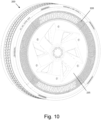
- Figure 10 is a perspective view of the non-pneumatic tire and rim assembly of Figure 6 having the upper cover 220 and a lower cover 235.
- the lower cover 235 is constructed of a rigid material, such as metal, polyethylene, polypropylene, glass-filled plastic, or other plastic. While the lower cover 235 is shown as a disk in this embodiment, it may be an annulus in other embodiments.
- Figure 11 is a cross-sectional view of the lower cover 235.
- the lower cover 235 includes a plurality of apertures 240.
- the lower cover 235 also has a circumferential groove 245 disposed on a rear surface.
- Figure 12 is a partial cross-sectional view of the non-pneumatic tire and rim assembly with the upper cover 220 and the lower cover 235 as shown in Figure 10 .
- the circumferential groove 245 of the lower cover 235 receives the circumferential projection 230 of the upper cover 220.
- the lower cover 235 may be mounted to the assembly by snapping the circumferential groove 245 of the lower cover 235 onto the circumferential projection 230 of the upper cover 220, or otherwise inserting the lower circumferential projection 230 of the upper cover 220 into the circumferential groove 245 of the lower cover 235.
- the lower cover 235 may be bolted to the rim 205 by passing bolts 250 through the apertures 240 of the lower cover 235 and through the slots 215 of the ears 210.
- Figures 1-5 illustrate an upper cover 135 in combination with a lower cover 160 and Figures 6-12 illustrate an upper cover 220 in combination with a lower cover 235, it should be understood that the disclosed covers, and the features of those covers are interchangeable.
Landscapes
- Engineering & Computer Science (AREA)
- Mechanical Engineering (AREA)
- Tires In General (AREA)
Claims (15)
- Pneu non pneumatique (100 ; 200), jante (130 ; 205), et ensemble de couvercle, l'ensemble comprenant :
un pneu non pneumatique (100 ; 200) comportant :un anneau inférieur (105) ayant un premier diamètre,un anneau supérieur (110) ayant un second diamètre supérieur au premier diamètre, l'anneau supérieur (110) étant sensiblement coaxial avec l'anneau inférieur (105), etune structure de support (115) s'étendant entre l'anneau inférieur (105) et l'anneau supérieur (110) ;une jante (130 ; 205) fixée à l'anneau inférieur (105) du pneu non pneumatique (100 ; 200) ;un couvercle supérieur (135 ; 220) fixé à un premier côté du pneu non pneumatique (100 ; 200),dans lequel le couvercle supérieur (135 ; 220) a une forme d'anneau qui couvre au moins une partie de la structure de support (115),dans lequel une partie inférieure du couvercle supérieur (135 ; 220) comporte une saillie circonférentielle (150 ; 230) qui fait saillie axialement vers l'extérieur par rapport à une région située au-dessus de la saillie circonférentielle (150 ; 230) ; etun couvercle inférieur (160 ; 235) fixé au couvercle supérieur (135 ; 220), dans lequel le couvercle inférieur (160 ; 235) comporte une rainure circonférentielle (175 ; 245) disposée sur une surface arrière qui reçoit la saillie circonférentielle (150 ; 230) du couvercle supérieur (135 ; 220). - Ensemble selon la revendication 1, dans lequel le couvercle supérieur (135 ; 220) est attaché au pneu non pneumatique (100 ; 200) en une pluralité d'endroits.
- Ensemble selon la revendication 1 ou 2, comprenant en outre un câble circulaire (140) attaché au pneu non pneumatique (100 ; 200) en une pluralité d'endroits, dans lequel le couvercle supérieur (135 ; 220) est attaché au câble circulaire (140).
- Ensemble selon la revendication 1 ou 2, dans lequel la saillie circonférentielle (150 ; 230) du couvercle supérieur (135 ; 220) est définie par un câble (155).
- Ensemble selon l'une quelconque des revendications 1 à 4, dans lequel le couvercle supérieur (135 ; 220) est constitué d'un matériau flexible.
- Ensemble selon l'une quelconque des revendications 1, 2, 4, ou 5, dans lequel le couvercle inférieur (160 ; 235) est attaché directement au pneu non pneumatique (100 ; 200).
- Ensemble selon l'une quelconque des revendications 1, 2, 4, ou 5, dans lequel le couvercle inférieur (160 ; 235) est attaché directement à la jante (130 ; 205).
- Ensemble selon l'une quelconque des revendications 1, 2, 4, ou 5, dans lequel le couvercle inférieur (160 ; 235) est attaché à au moins un connecteur (210) qui est attaché directement à la jante (130 ; 205).
- Ensemble selon l'une quelconque des revendications 1 à 8, dans lequel le couvercle inférieur (160 ; 235) a une face avant qui est un disque.
- Ensemble selon l'une quelconque des revendications 1 à 8, dans lequel le couvercle inférieur (160 ; 235) a une face avant qui est un anneau.
- Procédé de couverture d'un côté d'un pneu non pneumatique (100 ; 200), le procédé comprenant :
la fourniture d'un pneu non pneumatique (100 ; 200) comportant :un anneau inférieur (105) ayant un premier diamètre,un anneau supérieur (110) ayant un second diamètre supérieur au premier diamètre, l'anneau supérieur (110) étant sensiblement coaxial avec l'anneau inférieur (105), etune structure de support (115) s'étendant entre l'anneau inférieur (105) et l'anneau supérieur (110) ;la fourniture d'une jante (130 ; 205) ;le montage du pneu non pneumatique (100 ; 200) sur la jante (130 ; 205) ;la fourniture d'un couvercle supérieur (135 ; 220) ayant une forme d'anneau, dans lequel le couvercle supérieur (135 ; 220) a une saillie circonférentielle inférieure (150 ; 230) qui fait saillie axialement vers l'extérieur par rapport à une région située au-dessus de la saillie circonférentielle inférieure (150 ; 230) ;la fixation du couvercle supérieur (135 ; 220) au pneu non pneumatique (100 ; 200) ;la fourniture d'un couvercle inférieur (160 ; 235) comportant une rainure circonférentielle (175 ; 245) disposée sur une surface arrière ; etla fixation du couvercle inférieur (160 ; 235) sur le couvercle supérieur (135 ; 220) en insérant la saillie circonférentielle inférieure (150 ; 230) du couvercle supérieur (135 ; 220) dans la rainure circonférentielle (175 ; 245) du couvercle inférieur (160 ; 235). - Procédé selon la revendication 11, dans lequel la fourniture du couvercle supérieur (135 ; 220) comporte la fourniture d'un couvercle supérieur (135 ; 220) ayant une pluralité de saillies (225) disposées sur une surface arrière, et dans lequel la fixation du couvercle supérieur (135 ; 220) au pneu non pneumatique (100 ; 200) comporte l'insertion des saillies (225) du couvercle supérieur (135 ; 220) entre la structure de support (115) du pneu non pneumatique (100 ; 200).
- Procédé selon la revendication 11 ou 12, dans lequel la fixation du couvercle supérieur (135 ; 220) au pneu non pneumatique (100 ; 200) comporte l'attache d'un câble (140) au pneu non pneumatique (100 ; 200) et l'attache du couvercle supérieur (135 ; 220) au câble (140).
- Procédé selon l'une quelconque des revendications 11 à 13, comprenant en outre le boulonnage du couvercle inférieur (160 ; 235) à la jante (130 ; 205) avec des boulons à extension axiale (165 ; 250).
- Procédé selon l'une quelconque des revendications 11 à 13, comprenant en outre le boulonnage du couvercle inférieur (160 ; 235) à la jante (130 ; 205) avec des boulons à extension radiale.
Applications Claiming Priority (2)
| Application Number | Priority Date | Filing Date | Title |
|---|---|---|---|
| US201962954764P | 2019-12-30 | 2019-12-30 | |
| PCT/US2020/060737 WO2021137958A1 (fr) | 2019-12-30 | 2020-11-16 | Bandage non pneumatique muni de revêtements |
Publications (3)
| Publication Number | Publication Date |
|---|---|
| EP4084967A1 EP4084967A1 (fr) | 2022-11-09 |
| EP4084967A4 EP4084967A4 (fr) | 2024-01-10 |
| EP4084967B1 true EP4084967B1 (fr) | 2025-02-12 |
Family
ID=76685907
Family Applications (1)
| Application Number | Title | Priority Date | Filing Date |
|---|---|---|---|
| EP20909980.3A Active EP4084967B1 (fr) | 2019-12-30 | 2020-11-16 | Bandage non pneumatique muni de revêtements |
Country Status (5)
| Country | Link |
|---|---|
| US (1) | US12311707B2 (fr) |
| EP (1) | EP4084967B1 (fr) |
| JP (1) | JP7411096B2 (fr) |
| CN (1) | CN114901491A (fr) |
| WO (1) | WO2021137958A1 (fr) |
Families Citing this family (3)
| Publication number | Priority date | Publication date | Assignee | Title |
|---|---|---|---|---|
| US20250135808A1 (en) * | 2022-02-07 | 2025-05-01 | Bridgestone Americas Tire Operations, Llc | Tire having cantilevered sidewall shape and flexible support ring structure |
| KR102683548B1 (ko) * | 2023-05-26 | 2024-07-10 | 대동이브이 주식회사 | 트레드 교체가 용이한 비공기압 타이어와 이의 제조방법 |
| US20250319723A1 (en) * | 2024-04-15 | 2025-10-16 | Triangle Tyre Co. Ltd. | Non-Pneumatic Tire |
Family Cites Families (21)
| Publication number | Priority date | Publication date | Assignee | Title |
|---|---|---|---|---|
| US1424223A (en) * | 1921-02-19 | 1922-08-01 | Christian A Wagner | Tire |
| JPH0636901B2 (ja) | 1989-04-26 | 1994-05-18 | 東海ゴム工業株式会社 | ロールコーティング方法 |
| US4945962A (en) * | 1989-06-09 | 1990-08-07 | The Uniroyal Goodrich Tire Company | Honeycomb non-pneumatic tire with a single web on one side |
| JPH0748405Y2 (ja) * | 1992-10-20 | 1995-11-08 | 淳 野崎 | タイヤの装飾及び保護部材 |
| KR980007106U (ko) | 1996-07-26 | 1998-04-30 | 김영귀 | 자동차의 림 |
| US6688703B1 (en) * | 2003-04-02 | 2004-02-10 | Chu-Li Wang | Wheel rim cover |
| JP2006036901A (ja) | 2004-07-27 | 2006-02-09 | Matsushita Electric Ind Co Ltd | 有機物のガス化方法 |
| JP4723318B2 (ja) | 2005-06-22 | 2011-07-13 | 不二商事株式会社 | ホイール |
| US8555941B2 (en) * | 2010-08-12 | 2013-10-15 | The Boeing Company | Non-pneumatic survivable tire, cover and fabrication processes |
| KR101393891B1 (ko) * | 2012-08-29 | 2014-05-12 | 손영일 | 비공기압 타이어 |
| KR102219724B1 (ko) * | 2012-11-30 | 2021-02-25 | 허친슨 인더스트리스, 인코포레이티드 | 차량 타이어의 측벽용 보호기 쉴드, 및 상기 보호기 쉴드가 통합된 차량용 휠 조립체 |
| EP3086948B1 (fr) * | 2013-12-24 | 2020-03-11 | Bridgestone Americas Tire Operations, LLC | Conception de pneu sans air à rigidité variable |
| EP3142866A4 (fr) * | 2014-05-13 | 2018-01-10 | Hutchinson S.A. | Système de montage de protection de pneu |
| JP6377515B2 (ja) * | 2014-12-17 | 2018-08-22 | 東洋ゴム工業株式会社 | 非空気圧タイヤ |
| US20170174002A1 (en) * | 2015-12-21 | 2017-06-22 | The Goodyear Tire & Rubber Company | Non-pneumatic tire with geodesic connecting web |
| US20170368879A1 (en) * | 2016-06-28 | 2017-12-28 | The Goodyear Tire & Rubber Company | Non-pneumatic tire |
| WO2018200142A1 (fr) * | 2017-04-27 | 2018-11-01 | Bridgestone Americas Tire Operations, Llc | Pneu à boucles à rayons |
| US11021010B2 (en) * | 2017-06-12 | 2021-06-01 | Argonics, Inc. | Shielding assembly for side of tire |
| JP6978892B2 (ja) * | 2017-10-23 | 2021-12-08 | 住友ゴム工業株式会社 | エアレスタイヤ複合体 |
| US10749242B2 (en) * | 2017-10-30 | 2020-08-18 | The Goodyear Tire & Rubber Company | Non-pneumatic tire with radio frequency identification |
| US11772416B2 (en) * | 2020-10-06 | 2023-10-03 | The Goodyear Tire & Rubber Company | System for detection of non-pneumatic tire loading |
-
2020
- 2020-11-16 EP EP20909980.3A patent/EP4084967B1/fr active Active
- 2020-11-16 WO PCT/US2020/060737 patent/WO2021137958A1/fr not_active Ceased
- 2020-11-16 JP JP2022540680A patent/JP7411096B2/ja active Active
- 2020-11-16 CN CN202080090532.2A patent/CN114901491A/zh active Pending
- 2020-11-16 US US17/783,817 patent/US12311707B2/en active Active
Also Published As
| Publication number | Publication date |
|---|---|
| US20230010163A1 (en) | 2023-01-12 |
| JP7411096B2 (ja) | 2024-01-10 |
| CN114901491A (zh) | 2022-08-12 |
| WO2021137958A1 (fr) | 2021-07-08 |
| EP4084967A1 (fr) | 2022-11-09 |
| JP2023509047A (ja) | 2023-03-06 |
| US12311707B2 (en) | 2025-05-27 |
| EP4084967A4 (fr) | 2024-01-10 |
Similar Documents
| Publication | Publication Date | Title |
|---|---|---|
| EP4084967B1 (fr) | Bandage non pneumatique muni de revêtements | |
| EP0022741A2 (fr) | Ensemble d'écran protecteur pour flancs de pneumatiques | |
| WO2016100004A1 (fr) | Pneu non pneumatique avec support de centre de roue flexible polymère intégré | |
| EP3237228B1 (fr) | Ensemble pneu et roue à jante | |
| EP4084968B1 (fr) | Bandage non pneumatique comportant des enveloppes de flanc | |
| EP4084964B1 (fr) | Butée de suspension pour bandage non-pneumatique | |
| US10906351B2 (en) | Flexible wheel assembly | |
| JP2012041001A (ja) | タイヤガード、ホイール、及びタイヤ・ホイール組立体 | |
| EP4177078B1 (fr) | Pneu non pneumatique et ensemble roue et procédé de fabrication | |
| US20040035512A1 (en) | Tire/wheel assembly and pneumatic tire | |
| EP4084966B1 (fr) | Bandage non pneumatique ayant un revêtement de paroi latérale moulé | |
| EP3240700B1 (fr) | Pneu à parois latérales concaves | |
| US20250026150A1 (en) | System and method for protecting a support structure of a non-pneumatic tire | |
| CN114683770B (zh) | 免充气轮胎 | |
| US12552118B2 (en) | System and method for making a band and tread assembly for a non-pneumatic tire | |
| CN113226792A (zh) | 用于非充气轮胎的防溅控制带 | |
| WO2022145000A1 (fr) | Adaptateur pour ensemble roulant |
Legal Events
| Date | Code | Title | Description |
|---|---|---|---|
| STAA | Information on the status of an ep patent application or granted ep patent |
Free format text: STATUS: THE INTERNATIONAL PUBLICATION HAS BEEN MADE |
|
| PUAI | Public reference made under article 153(3) epc to a published international application that has entered the european phase |
Free format text: ORIGINAL CODE: 0009012 |
|
| STAA | Information on the status of an ep patent application or granted ep patent |
Free format text: STATUS: REQUEST FOR EXAMINATION WAS MADE |
|
| 17P | Request for examination filed |
Effective date: 20220715 |
|
| AK | Designated contracting states |
Kind code of ref document: A1 Designated state(s): AL AT BE BG CH CY CZ DE DK EE ES FI FR GB GR HR HU IE IS IT LI LT LU LV MC MK MT NL NO PL PT RO RS SE SI SK SM TR |
|
| DAV | Request for validation of the european patent (deleted) | ||
| DAX | Request for extension of the european patent (deleted) | ||
| A4 | Supplementary search report drawn up and despatched |
Effective date: 20231213 |
|
| RIC1 | Information provided on ipc code assigned before grant |
Ipc: B60B 9/00 20060101ALI20231207BHEP Ipc: B60B 7/06 20060101ALI20231207BHEP Ipc: B60B 7/01 20060101ALI20231207BHEP Ipc: B60C 13/04 20060101ALI20231207BHEP Ipc: B60C 11/03 20060101ALI20231207BHEP Ipc: B60C 13/00 20060101ALI20231207BHEP Ipc: B60C 7/14 20060101ALI20231207BHEP Ipc: B60B 9/10 20060101ALI20231207BHEP Ipc: B60C 7/10 20060101AFI20231207BHEP |
|
| RIC1 | Information provided on ipc code assigned before grant |
Ipc: B60B 9/00 20060101ALI20240813BHEP Ipc: B60B 7/06 20060101ALI20240813BHEP Ipc: B60B 7/01 20060101ALI20240813BHEP Ipc: B60C 13/04 20060101ALI20240813BHEP Ipc: B60C 11/03 20060101ALI20240813BHEP Ipc: B60C 13/00 20060101ALI20240813BHEP Ipc: B60C 7/14 20060101ALI20240813BHEP Ipc: B60B 9/10 20060101ALI20240813BHEP Ipc: B60C 7/10 20060101AFI20240813BHEP |
|
| GRAP | Despatch of communication of intention to grant a patent |
Free format text: ORIGINAL CODE: EPIDOSNIGR1 |
|
| STAA | Information on the status of an ep patent application or granted ep patent |
Free format text: STATUS: GRANT OF PATENT IS INTENDED |
|
| INTG | Intention to grant announced |
Effective date: 20241023 |
|
| GRAS | Grant fee paid |
Free format text: ORIGINAL CODE: EPIDOSNIGR3 |
|
| GRAA | (expected) grant |
Free format text: ORIGINAL CODE: 0009210 |
|
| STAA | Information on the status of an ep patent application or granted ep patent |
Free format text: STATUS: THE PATENT HAS BEEN GRANTED |
|
| P01 | Opt-out of the competence of the unified patent court (upc) registered |
Free format text: CASE NUMBER: APP_65623/2024 Effective date: 20241212 |
|
| AK | Designated contracting states |
Kind code of ref document: B1 Designated state(s): AL AT BE BG CH CY CZ DE DK EE ES FI FR GB GR HR HU IE IS IT LI LT LU LV MC MK MT NL NO PL PT RO RS SE SI SK SM TR |
|
| REG | Reference to a national code |
Ref country code: GB Ref legal event code: FG4D |
|
| REG | Reference to a national code |
Ref country code: CH Ref legal event code: EP |
|
| REG | Reference to a national code |
Ref country code: DE Ref legal event code: R096 Ref document number: 602020046141 Country of ref document: DE |
|
| REG | Reference to a national code |
Ref country code: IE Ref legal event code: FG4D |
|
| REG | Reference to a national code |
Ref country code: NL Ref legal event code: MP Effective date: 20250212 |
|
| PG25 | Lapsed in a contracting state [announced via postgrant information from national office to epo] |
Ref country code: RS Free format text: LAPSE BECAUSE OF FAILURE TO SUBMIT A TRANSLATION OF THE DESCRIPTION OR TO PAY THE FEE WITHIN THE PRESCRIBED TIME-LIMIT Effective date: 20250512 |
|
| PG25 | Lapsed in a contracting state [announced via postgrant information from national office to epo] |
Ref country code: FI Free format text: LAPSE BECAUSE OF FAILURE TO SUBMIT A TRANSLATION OF THE DESCRIPTION OR TO PAY THE FEE WITHIN THE PRESCRIBED TIME-LIMIT Effective date: 20250212 |
|
| PG25 | Lapsed in a contracting state [announced via postgrant information from national office to epo] |
Ref country code: PL Free format text: LAPSE BECAUSE OF FAILURE TO SUBMIT A TRANSLATION OF THE DESCRIPTION OR TO PAY THE FEE WITHIN THE PRESCRIBED TIME-LIMIT Effective date: 20250212 |
|
| PG25 | Lapsed in a contracting state [announced via postgrant information from national office to epo] |
Ref country code: ES Free format text: LAPSE BECAUSE OF FAILURE TO SUBMIT A TRANSLATION OF THE DESCRIPTION OR TO PAY THE FEE WITHIN THE PRESCRIBED TIME-LIMIT Effective date: 20250212 |
|
| REG | Reference to a national code |
Ref country code: LT Ref legal event code: MG9D |
|
| PG25 | Lapsed in a contracting state [announced via postgrant information from national office to epo] |
Ref country code: IS Free format text: LAPSE BECAUSE OF FAILURE TO SUBMIT A TRANSLATION OF THE DESCRIPTION OR TO PAY THE FEE WITHIN THE PRESCRIBED TIME-LIMIT Effective date: 20250612 Ref country code: NO Free format text: LAPSE BECAUSE OF FAILURE TO SUBMIT A TRANSLATION OF THE DESCRIPTION OR TO PAY THE FEE WITHIN THE PRESCRIBED TIME-LIMIT Effective date: 20250512 |
|
| PG25 | Lapsed in a contracting state [announced via postgrant information from national office to epo] |
Ref country code: NL Free format text: LAPSE BECAUSE OF FAILURE TO SUBMIT A TRANSLATION OF THE DESCRIPTION OR TO PAY THE FEE WITHIN THE PRESCRIBED TIME-LIMIT Effective date: 20250212 |
|
| PG25 | Lapsed in a contracting state [announced via postgrant information from national office to epo] |
Ref country code: HR Free format text: LAPSE BECAUSE OF FAILURE TO SUBMIT A TRANSLATION OF THE DESCRIPTION OR TO PAY THE FEE WITHIN THE PRESCRIBED TIME-LIMIT Effective date: 20250212 |
|
| PG25 | Lapsed in a contracting state [announced via postgrant information from national office to epo] |
Ref country code: PT Free format text: LAPSE BECAUSE OF FAILURE TO SUBMIT A TRANSLATION OF THE DESCRIPTION OR TO PAY THE FEE WITHIN THE PRESCRIBED TIME-LIMIT Effective date: 20250612 Ref country code: LV Free format text: LAPSE BECAUSE OF FAILURE TO SUBMIT A TRANSLATION OF THE DESCRIPTION OR TO PAY THE FEE WITHIN THE PRESCRIBED TIME-LIMIT Effective date: 20250212 |
|
| PG25 | Lapsed in a contracting state [announced via postgrant information from national office to epo] |
Ref country code: GR Free format text: LAPSE BECAUSE OF FAILURE TO SUBMIT A TRANSLATION OF THE DESCRIPTION OR TO PAY THE FEE WITHIN THE PRESCRIBED TIME-LIMIT Effective date: 20250513 Ref country code: BG Free format text: LAPSE BECAUSE OF FAILURE TO SUBMIT A TRANSLATION OF THE DESCRIPTION OR TO PAY THE FEE WITHIN THE PRESCRIBED TIME-LIMIT Effective date: 20250212 |
|
| REG | Reference to a national code |
Ref country code: AT Ref legal event code: MK05 Ref document number: 1765765 Country of ref document: AT Kind code of ref document: T Effective date: 20250212 |
|
| PG25 | Lapsed in a contracting state [announced via postgrant information from national office to epo] |
Ref country code: SE Free format text: LAPSE BECAUSE OF FAILURE TO SUBMIT A TRANSLATION OF THE DESCRIPTION OR TO PAY THE FEE WITHIN THE PRESCRIBED TIME-LIMIT Effective date: 20250212 |
|
| PG25 | Lapsed in a contracting state [announced via postgrant information from national office to epo] |
Ref country code: SM Free format text: LAPSE BECAUSE OF FAILURE TO SUBMIT A TRANSLATION OF THE DESCRIPTION OR TO PAY THE FEE WITHIN THE PRESCRIBED TIME-LIMIT Effective date: 20250212 |
|
| PG25 | Lapsed in a contracting state [announced via postgrant information from national office to epo] |
Ref country code: DK Free format text: LAPSE BECAUSE OF FAILURE TO SUBMIT A TRANSLATION OF THE DESCRIPTION OR TO PAY THE FEE WITHIN THE PRESCRIBED TIME-LIMIT Effective date: 20250212 |
|
| PG25 | Lapsed in a contracting state [announced via postgrant information from national office to epo] |
Ref country code: IT Free format text: LAPSE BECAUSE OF FAILURE TO SUBMIT A TRANSLATION OF THE DESCRIPTION OR TO PAY THE FEE WITHIN THE PRESCRIBED TIME-LIMIT Effective date: 20250212 |
|
| PG25 | Lapsed in a contracting state [announced via postgrant information from national office to epo] |
Ref country code: AT Free format text: LAPSE BECAUSE OF FAILURE TO SUBMIT A TRANSLATION OF THE DESCRIPTION OR TO PAY THE FEE WITHIN THE PRESCRIBED TIME-LIMIT Effective date: 20250212 |
|
| PG25 | Lapsed in a contracting state [announced via postgrant information from national office to epo] |
Ref country code: EE Free format text: LAPSE BECAUSE OF FAILURE TO SUBMIT A TRANSLATION OF THE DESCRIPTION OR TO PAY THE FEE WITHIN THE PRESCRIBED TIME-LIMIT Effective date: 20250212 Ref country code: CZ Free format text: LAPSE BECAUSE OF FAILURE TO SUBMIT A TRANSLATION OF THE DESCRIPTION OR TO PAY THE FEE WITHIN THE PRESCRIBED TIME-LIMIT Effective date: 20250212 |
|
| PG25 | Lapsed in a contracting state [announced via postgrant information from national office to epo] |
Ref country code: RO Free format text: LAPSE BECAUSE OF FAILURE TO SUBMIT A TRANSLATION OF THE DESCRIPTION OR TO PAY THE FEE WITHIN THE PRESCRIBED TIME-LIMIT Effective date: 20250212 |
|
| PG25 | Lapsed in a contracting state [announced via postgrant information from national office to epo] |
Ref country code: SK Free format text: LAPSE BECAUSE OF FAILURE TO SUBMIT A TRANSLATION OF THE DESCRIPTION OR TO PAY THE FEE WITHIN THE PRESCRIBED TIME-LIMIT Effective date: 20250212 |
|
| REG | Reference to a national code |
Ref country code: DE Ref legal event code: R097 Ref document number: 602020046141 Country of ref document: DE |
|
| PLBE | No opposition filed within time limit |
Free format text: ORIGINAL CODE: 0009261 |
|
| STAA | Information on the status of an ep patent application or granted ep patent |
Free format text: STATUS: NO OPPOSITION FILED WITHIN TIME LIMIT |
|
| PGFP | Annual fee paid to national office [announced via postgrant information from national office to epo] |
Ref country code: DE Payment date: 20251022 Year of fee payment: 6 |
|
| PGFP | Annual fee paid to national office [announced via postgrant information from national office to epo] |
Ref country code: FR Payment date: 20251022 Year of fee payment: 6 |
|
| 26N | No opposition filed |
Effective date: 20251113 |