EP4084968B1 - Luftloser reifen mit seitenwandabdeckungen - Google Patents
Luftloser reifen mit seitenwandabdeckungen Download PDFInfo
- Publication number
- EP4084968B1 EP4084968B1 EP20910056.9A EP20910056A EP4084968B1 EP 4084968 B1 EP4084968 B1 EP 4084968B1 EP 20910056 A EP20910056 A EP 20910056A EP 4084968 B1 EP4084968 B1 EP 4084968B1
- Authority
- EP
- European Patent Office
- Prior art keywords
- sidewall
- pneumatic tire
- cover
- sidewall cover
- ring
- Prior art date
- Legal status (The legal status is an assumption and is not a legal conclusion. Google has not performed a legal analysis and makes no representation as to the accuracy of the status listed.)
- Active
Links
Images


Classifications
-
- B—PERFORMING OPERATIONS; TRANSPORTING
- B60—VEHICLES IN GENERAL
- B60C—VEHICLE TYRES; TYRE INFLATION; TYRE CHANGING; CONNECTING VALVES TO INFLATABLE ELASTIC BODIES IN GENERAL; DEVICES OR ARRANGEMENTS RELATED TO TYRES
- B60C7/00—Non-inflatable or solid tyres
- B60C7/10—Non-inflatable or solid tyres characterised by means for increasing resiliency
- B60C7/14—Non-inflatable or solid tyres characterised by means for increasing resiliency using springs
- B60C7/143—Non-inflatable or solid tyres characterised by means for increasing resiliency using springs having a lateral extension disposed in a plane parallel to the wheel axis
-
- B—PERFORMING OPERATIONS; TRANSPORTING
- B60—VEHICLES IN GENERAL
- B60B—VEHICLE WHEELS; CASTORS; AXLES FOR WHEELS OR CASTORS; INCREASING WHEEL ADHESION
- B60B7/00—Wheel cover discs, rings, or the like, for ornamenting, protecting, venting, or obscuring, wholly or in part, the wheel body, rim, hub, or tyre sidewall, e.g. wheel cover discs, wheel cover discs with cooling fins
- B60B7/01—Rings specially adapted for covering only the wheel rim or the tyre sidewall, e.g. removable tyre sidewall trim rings
-
- B—PERFORMING OPERATIONS; TRANSPORTING
- B60—VEHICLES IN GENERAL
- B60B—VEHICLE WHEELS; CASTORS; AXLES FOR WHEELS OR CASTORS; INCREASING WHEEL ADHESION
- B60B9/00—Wheels of high resiliency, e.g. with conical interacting pressure-surfaces
- B60B9/26—Wheels of high resiliency, e.g. with conical interacting pressure-surfaces comprising resilient spokes
-
- B—PERFORMING OPERATIONS; TRANSPORTING
- B60—VEHICLES IN GENERAL
- B60C—VEHICLE TYRES; TYRE INFLATION; TYRE CHANGING; CONNECTING VALVES TO INFLATABLE ELASTIC BODIES IN GENERAL; DEVICES OR ARRANGEMENTS RELATED TO TYRES
- B60C11/00—Tyre tread bands; Tread patterns; Anti-skid inserts
- B60C11/03—Tread patterns
- B60C11/0306—Patterns comprising block rows or discontinuous ribs
-
- B—PERFORMING OPERATIONS; TRANSPORTING
- B60—VEHICLES IN GENERAL
- B60C—VEHICLE TYRES; TYRE INFLATION; TYRE CHANGING; CONNECTING VALVES TO INFLATABLE ELASTIC BODIES IN GENERAL; DEVICES OR ARRANGEMENTS RELATED TO TYRES
- B60C13/00—Tyre sidewalls; Protecting, decorating, marking, or the like, thereof
- B60C13/002—Protection against exterior elements
-
- B—PERFORMING OPERATIONS; TRANSPORTING
- B60—VEHICLES IN GENERAL
- B60C—VEHICLE TYRES; TYRE INFLATION; TYRE CHANGING; CONNECTING VALVES TO INFLATABLE ELASTIC BODIES IN GENERAL; DEVICES OR ARRANGEMENTS RELATED TO TYRES
- B60C13/00—Tyre sidewalls; Protecting, decorating, marking, or the like, thereof
- B60C13/04—Tyre sidewalls; Protecting, decorating, marking, or the like, thereof having annular inlays or covers, e.g. white sidewalls
-
- B—PERFORMING OPERATIONS; TRANSPORTING
- B60—VEHICLES IN GENERAL
- B60C—VEHICLE TYRES; TYRE INFLATION; TYRE CHANGING; CONNECTING VALVES TO INFLATABLE ELASTIC BODIES IN GENERAL; DEVICES OR ARRANGEMENTS RELATED TO TYRES
- B60C7/00—Non-inflatable or solid tyres
- B60C7/10—Non-inflatable or solid tyres characterised by means for increasing resiliency
- B60C7/107—Non-inflatable or solid tyres characterised by means for increasing resiliency comprising lateral openings
-
- B—PERFORMING OPERATIONS; TRANSPORTING
- B60—VEHICLES IN GENERAL
- B60C—VEHICLE TYRES; TYRE INFLATION; TYRE CHANGING; CONNECTING VALVES TO INFLATABLE ELASTIC BODIES IN GENERAL; DEVICES OR ARRANGEMENTS RELATED TO TYRES
- B60C7/00—Non-inflatable or solid tyres
- B60C7/10—Non-inflatable or solid tyres characterised by means for increasing resiliency
- B60C7/12—Non-inflatable or solid tyres characterised by means for increasing resiliency using enclosed chambers, e.g. gas-filled
- B60C7/125—Non-inflatable or solid tyres characterised by means for increasing resiliency using enclosed chambers, e.g. gas-filled enclosed chambers defined between rim and tread
-
- B—PERFORMING OPERATIONS; TRANSPORTING
- B60—VEHICLES IN GENERAL
- B60C—VEHICLE TYRES; TYRE INFLATION; TYRE CHANGING; CONNECTING VALVES TO INFLATABLE ELASTIC BODIES IN GENERAL; DEVICES OR ARRANGEMENTS RELATED TO TYRES
- B60C7/00—Non-inflatable or solid tyres
- B60C7/10—Non-inflatable or solid tyres characterised by means for increasing resiliency
- B60C7/14—Non-inflatable or solid tyres characterised by means for increasing resiliency using springs
- B60C7/146—Non-inflatable or solid tyres characterised by means for increasing resiliency using springs extending substantially radially, e.g. like spokes
-
- B—PERFORMING OPERATIONS; TRANSPORTING
- B60—VEHICLES IN GENERAL
- B60B—VEHICLE WHEELS; CASTORS; AXLES FOR WHEELS OR CASTORS; INCREASING WHEEL ADHESION
- B60B9/00—Wheels of high resiliency, e.g. with conical interacting pressure-surfaces
Definitions
- the present invention relates to a non-pneumatic tire having sidewalls. More particularly, the present invention relates to a non-pneumatic tire having two-piece sidewall covers.
- Non-pneumatic tires do not require inflation, while "run flat tires” may continue to operate after receiving a puncture and a complete or partial loss of pressurized air, for extended periods of time and at relatively high speeds.
- Non-pneumatic tires may include a plurality of spokes, a webbing, or other support structure that connects a lower ring to an upper ring.
- US 1 424 223 A describes a vehicle tire. Its aim is to provide a vehicle tire wherein pneumatic elements, subject to puncture and deterioration, may be dispensed with.
- KR 2014 0028473 A describes a non-pneumatic tire including a tire body which includes a tire wheel, a non-pneumatic circular inner wheel which a plurality of first bumping ribs is arranged between the tire wheel and the non-pneumatic circular inner wheel, and a non-pneumatic circular outer wheel which a plurality of second bumping ribs is arranged between the non-pneumatic circular inner wheel and the non-pneumatic circular outer wheel; circular rings which are arranged on both sides of the tire body and which resists an external force and maintains the shape of the non-pneumatic circular inner wheel; and tire covers which are arranged on the outer side of the non-pneumatic circular outer wheel to partially cover the non-pneumatic circular outer wheel and joined to the circular rings.
- US 2015/122382 A1 describes a non-pneumatic tire that includes a tread, a rim part, inside and outside annular bands, a spoke member, and a pair of protective films.
- the tread comes into contact with a road surface.
- the rim part is connected to the axle of a vehicle.
- the inside and outside annular bands are disposed between the tread and the rim part, and are coaxially spaced apart from each other.
- the spoke member includes supports disposed in a predetermined pattern and configured to connect the inside and outside annular bands, and openings defined by the supports.
- the pair of protective films are disposed at both ends of the tire in the widthwise direction of the tire, and prevents foreign substances from infiltrating into the openings of the spoke member.
- the protective films are made of the same material as the spoke member and integrated with the spoke member.
- a non-pneumatic tire, rim, and sidewall assembly includes a non-pneumatic tire having a lower ring with a first diameter, and an upper ring with a second diameter greater than the first diameter.
- the upper ring is substantially coaxial with the lower ring.
- the non-pneumatic tire further includes support structure extending between the lower ring and the upper ring.
- the assembly further includes a rim connected to the lower ring of the non-pneumatic tire.
- the assembly also has a lower sidewall cover connected to the rim.
- the lower sidewall cover includes an annulus portion that covers a first side of the lower ring and a portion of a first side of the support structure.
- the annulus portion of the lower sidewall cover has an inner diameter that is less than the first diameter.
- the annulus portion of the lower sidewall cover has an outer diameter that is less than the second diameter.
- the assembly also includes an upper sidewall cover having an annulus shape that covers a portion of the first side of the support structure.
- the upper sidewall cover has an inner diameter that is less than the outer diameter of the annulus portion of the lower sidewall cover.
- a method of covering a side of a non-pneumatic tire includes providing a non-pneumatic tire having a lower ring with a first diameter, an upper ring with a second diameter greater than the first diameter, and support structure extending between the lower ring and the upper ring.
- the upper ring is substantially coaxial with the lower ring.
- the method further includes providing a rim and mounting the non-pneumatic tire on the rim.
- the method also includes providing a lower sidewall having an annulus portion and connecting the lower sidewall to the rim such that the annulus portion of the lower sidewall covers a first side of the lower ring and a lower portion of a first side of the support structure, and such that the lower sidewall does not cover an upper portion of the first side of the support structure.
- a non-pneumatic tire includes a lower ring having a first diameter and an upper ring having a second diameter greater than the first diameter.
- the upper ring is substantially coaxial with the lower ring.
- the non-pneumatic tire further includes support structure extending between the lower ring and the upper ring.
- the non-pneumatic tire also includes an upper sidewall having an annulus shape that covers a portion of a first side of the support structure.
- the upper sidewall has an inner diameter that is greater than the first diameter.
- Axial and “axially” refer to a direction that is parallel to the axis of rotation of a tire.
- “Circumferential” and “circumferentially” refer to a direction extending along the perimeter of the surface of the tread perpendicular to the axial direction.
- Ring and radially refer to a direction perpendicular to the axis of rotation of a tire.
- Thread refers to that portion of the tire that comes into contact with the road or ground under normal inflation and normal load.
- inward and outwardly refer to a general direction towards the equatorial plane of the tire
- outward and outwardly refer to a general direction away from the equatorial plane of the tire and towards the sidewall of the tire.
- relative directional terms such as “inner” and “outer” are used in connection with an element, the “inner” element is spaced closer to the equatorial plane of the tire than the “outer” element.
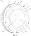
- Figure 1 is a partial perspective view of one embodiment of a non-pneumatic tire and rim assembly.
- the assembly includes a non-pneumatic tire 100 having a lower ring 105 with a first diameter, and an upper ring 110 having a second diameter greater than the first diameter.
- the upper ring 110 is substantially coaxial with the lower ring 105.
- a plurality of spokes 115 extend between the lower ring 105 and the upper ring 110.
- a plurality of fillets 120 are disposed between the lower ring 105 and the upper ring 110 at the end of each spoke 115.
- the plurality of fillets 120 includes lower fillets 120 l and upper fillets 120 u .
- the lower fillets 120 l are in direct contact with the lower ring 105.
- the upper fillets 120 u are in direct contact with the upper ring 110.
- the fillets may be omitted.
- a plurality of ears 125 are disposed between pairs of adjacent spokes 115.
- Each ear 125 includes an aperture 130.
- the aperture 130 may be a threaded aperture or a smooth aperture. In an alternative embodiment, the ears may be omitted.
- a webbing or other support structure may be employed instead of spokes.
- a circumferential tread 135 is disposed about the upper ring 110 in the illustrated embodiment.
- the tread 135 may include tread elements such as grooves, ribs, blocks, lugs, sipes, studs, and other elements.
- a shear band or other shear element or reinforcement structure (not shown) may be disposed between the upper ring 110 and the tread 135.
- the separate tread may be omitted and instead tread elements may be formed directly on the upper ring.
- the lower and upper rings 105, 110 may be constructed of a polymeric material, such as natural or synthetic rubber, other elastomeric material.
- the lower and upper rings 105, 110 may be constructed of a harder polymeric material such as polyurethane, polyester, nylon or polyvinyl chloride (PVC).
- the spokes 115 may be constructed of elastomeric material having a single layer of reinforcement disposed therein.
- the tread 135, fillets 120, and ears 125 may be constructed of an elastomeric material, such as natural or synthetic rubber, or other elastomeric material.
- the assembly further includes a rim 140.
- the lower ring 105 is attached to the rim 140 , such as by an adhesive or through a chemical bonding process.
- the rim 140 may be attached to a vehicle through a plurality of bolts (not shown) that extend through apertures 145.
- FIG 2 is a perspective view of the non-pneumatic tire and rim assembly having an upper sidewall cover 150.
- the upper sidewall cover 150 may also be simply referred to as the upper sidewall or the upper cover.
- the upper sidewall cover 150 has an annulus shape that covers a portion of a first side of the non-pneumatic tire 100. Specifically, the upper sidewall cover 150 covers a portion of the spokes 115.
- the upper sidewall cover 150 has an inner diameter that is greater than the diameter of the lower ring 105.
- the upper fillets 120 u and upper portions of the spokes 115 are covered by the upper sidewall cover 150, while the lower ring 105, the lower fillets 120 l , and lower portions of the spokes 115 are uncovered.
- the upper ring 110 is covered by the upper sidewall cover 150.
- the outer diameter of the upper sidewall cover 150 is greater than the diameter of the upper ring 110.
- the upper ring 110 is uncovered. In other words, in such an embodiment the outer diameter of the upper sidewall cover 150 is less than the diameter of the upper ring 110.
- a shoulder region of the tread 135 is covered by the sidewall cover 150, while in an alternative embodiment, the shoulder region of the tread 135 is uncovered.
- the upper sidewall cover 150 is directly attached to the non-pneumatic tire 100 at a plurality of locations. Specifically, the upper sidewall cover 150 is bolted to the non-pneumatic tire 100 with bolts 155 extending into the apertures 130 of the ears 125. Thus, the upper sidewall cover 150 is removeably attached to the non-pneumatic tire 100. In alternative embodiments, other removable fasteners such as clips may be employed. In another alternative embodiment, the upper sidewall cover may be permanently attached to the non-pneumatic tire by adhesive or permanent fasteners.
- Figure 3 is a cross-sectional view of the assembly shown in Figure 2 .
- the upper sidewall cover 150 includes an upper angled portion 160, a radial portion 165, and a lower angled portion 170.
- an upper portion of the upper sidewall cover 150 is bent inwards towards the non-pneumatic tire 100, and a lower portion of the upper sidewall cover 150 is likewise bent inwards towards the non-pneumatic tire 100.
- the angled lower portion is bent away from the non-pneumatic tire.
- the lower portion of the upper sidewall cover extends in a radial direction.
- the upper portion of the upper sidewall cover extends in a radial direction.
- the upper sidewall cover is a flat, disc-shaped component.
- the annulus portion 180 of the lower sidewall cover 175 has an inner diameter that is less than the diameter of the inner ring 105, and an outer diameter that is less than the diameter of the outer ring 110.
- the lower ring 105, the lower fillets 120 l , and lower portions of the spokes 115 are covered by the annulus portion 180 of the lower sidewall cover 175, while the upper fillets 120 u and upper portions of the spokes 115 are uncovered.
- the lower sidewall cover 175 also includes a cylinder 185 that has a diameter less than a diameter of the rim 135.
- the cylinder 185 thus can be received by the rim 135.
- the annulus portion 180 of the lower sidewall cover 175 extends radially outward from a first end of the cylinder 185.
- An annular wall 190 extends radially inward from a second end of the cylinder 185.
- the annular wall 190 includes a plurality of apertures (not shown) that align with bolts B that pass through apertures in the rim, thus allowing the annular wall 190 to be bolted to the rim 140.
- the lower sidewall cover 175 is directly attached to the rim 135 at a plurality of locations.
- the lower sidewall cover 175 is removeably attached to the non-pneumatic tire and rim assembly.
- other removable fasteners may be employed.
- the lower sidewall cover may be permanently attached to the non-pneumatic tire and rim assembly by adhesive or permanent fasteners.
- the lower sidewall cover 175 may be attached to rim 135, it should be understood that the lower sidewall cover may be attached at other locations.
- the lower sidewall cover may be attached to the lower ring, the lower fillets, or the spokes or other support structure.
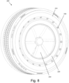
- Figure 6 is a perspective view of the non-pneumatic tire and rim assembly having both an upper sidewall cover 150 and a lower sidewall cover 175. While a user may employ only the upper sidewall cover, as shown in Figures 2 and 3 , or only the lower sidewall cover 175 as shown in Figures 4 and 5 , it may be desirable to employ both the upper sidewall cover 150 and the lower sidewall cover 175 as shown in Figure 6 .
- a cap 199 is also attached to the lower sidewall cover 175 to cover the central opening. The cap 199 is optional.
- Figure 7 is a cross-sectional view of the non-pneumatic tire and rim assembly having an upper sidewall cover 150 and a lower sidewall cover 175 as shown in Figure 6 .
- the upper sidewall cover 150 includes an upper angled portion 160, a radial portion 165, and a lower angled portion 170.
- an upper portion of the upper sidewall cover 150 is bent inwards towards the non-pneumatic tire 100, and a lower portion of the upper sidewall cover 150 is bent inwards towards the non-pneumatic tire 100.
- the annulus portion 180 of the lower sidewall cover 175 includes an upper angled portion 195, a radial portion 196, and a lower angled portion 197.
- an upper portion of the lower sidewall cover 175 is bent outwards away from the non-pneumatic tire 100, and a lower portion of the lower sidewall cover 175 is also bent outwards away from the non-pneumatic tire 100.
- the lower angled portion 170 of the upper sidewall cover 150 is radially below the upper angled portion 195 of the lower sidewall cover 175.
- the two angled portions thus form a labyrinthine, or torturous path, to further prevent debris from entering the openings of the tire 100.
- the upper and lower sidewall covers could be bent in opposite directions.
- the angled upper portion of the lower sidewall cap may be bent toward the non-pneumatic tire, while the angled lower portion of the upper sidewall cap is bent away from the non-pneumatic tire.
- Such a configuration would still result in a labyrinthine, or torturous path.
- the upper and lower sidewall covers simply overlap each other in a radial direction, without forming a labyrinthine or torturous path. Such a configuration may be easier to manufacture and assemble.
- Figure 8 is a perspective view of an alternative embodiment of a non-pneumatic tire and rim assembly having an upper sidewall cover and a lower sidewall cover.
- the non-pneumatic tire 200 may be substantially the same as the non-pneumatic tire 100, or any of the alternative embodiments described above. Thus, the non-pneumatic tire 200 is not described in further detail.
- the non-pneumatic tire 200 includes an upper sidewall cover 210 and a lower sidewall cover 220.
- the upper and lower sidewall covers 210, 220 are substantially the same as the upper and lower sidewall covers 150, 175 described above except for the differences detailed herein.
- the lower sidewall cover 220 is directly attached to the upper sidewall cover 210 by a plurality of bolts 230. In an alternative embodiment, other temporary or permanent fasteners may be employed.
- the upper sidewall cover 210 is not directly attached to the non-pneumatic tire 200. Instead, the upper sidewall cover 210 may move radially (or float) with respect to the non-pneumatic tire if the spokes of the tire buckle or flex.
- the assembly also includes a cap 240 attached to the lower sidewall cover 220.
- the cap may be omitted.
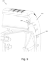
- Figure 9 is a cross-sectional view of the non-pneumatic tire and rim assembly having an upper sidewall cover 210 and a lower sidewall cover 220 as shown in Figure 8 .
- the upper and lower sidewall covers 210, 220 have the same bent configurations as the upper and lower sidewall covers 150, 175 shown in Figure 6 . It should be understood that the alternatives described with respect to Figure 6 may also apply to the embodiment shown in Figure 8 .
- Figure 10 is a perspective view of an alternative embodiment of an upper sidewall cover 310 and a lower sidewall cover 320.
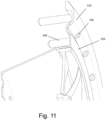
- Figure 11 is a cross-sectional view of the upper sidewall cover and the lower sidewall cover as shown in Figure 10 .
- the upper sidewall cover 310 and lower sidewall cover 320 are directly attached to each other with a plurality of bolts 330.
- the upper and lower sidewall covers 310, 320 are substantially the same as the upper sidewall cover 210 and lower sidewall cover 220 described above with respect to Figures 8 and 9 , except for the differences described herein.
- the upper sidewall cover 310 includes a plurality of projections 340 extending axially inward.
- the projections are dimensioned to fit in between the spokes of a non-pneumatic tire and may provide additional stability and prevent twisting.
- the projections are dimensioned to provide a force fit attachment to the tire.
- the projections may have a textured surface or have features molded therein to increase the friction between the projections and spokes.
- the projections 340 are shown as having a constant diameter, in an alternative embodiment the projections may be tapered. In an alternative embodiment, the projections have a smaller dimension such that there is a clearance between the projections and the spokes.
Landscapes
- Engineering & Computer Science (AREA)
- Mechanical Engineering (AREA)
- Tires In General (AREA)
Claims (13)
- Nicht-Luftreifen- (100; 200), Felgen- (140) und Seitenwandbaugruppe, die Baugruppe umfassend:
einen Nicht-Luftreifen (100, 200), der einschließt:einen unteren Ring (105), der einen ersten Durchmesser aufweist,einen oberen Ring (110), der einen zweiten Durchmesser aufweist, der größer als der erste Durchmesser ist, wobei der obere Ring (110) im Wesentlichen koaxial zu dem unteren Ring (105) ist, undeine Stützstruktur (115), die sich zwischen dem unteren Ring (105) und dem oberen Ring (110) erstreckt;eine Felge (140), die mit dem unteren Ring (105) des Nicht-Luftreifens (100; 200) verbunden ist;eine untere Seitenwandabdeckung (175; 220; 320), die mit der Felge (140) verbunden ist, wobei die untere Seitenwandabdeckung (175; 220; 320) einen ringförmigen Abschnitt (180) einschließt, der eine erste Seite des unteren Rings (105) und einen Abschnitt einer ersten Seite der Stützstruktur (115) abdeckt,wobei der ringförmige Abschnitt (180) der unteren Seitenwandabdeckung (175; 220; 320) einen Innendurchmesser aufweist, der kleiner als der erste Durchmesser ist, undwobei der ringförmige Abschnitt (180) der unteren Seitenwandabdeckung (175; 220; 321) einen Außendurchmesser aufweist, der kleiner als der zweite Durchmesser ist,wobei ein unterer Abschnitt der oberen Seitenwandabdeckung (150; 210; 310) nach innen zu den Nicht-Luftreifen (100; 200) hin gebogen ist, undwobei ein oberer Abschnitt der unteren Seitenwandabdeckung (175; 220; 320) nach außen von dem Nicht-Luftreifen (100; 200) weg gebogen ist;eine obere Seitenwandabdeckung (150; 210; 310), die eine ringförmige Form aufweist, die einen Abschnitt der ersten Seite der Stützstruktur (115) abdeckt,wobei die obere Seitenwandabdeckung (150; 210; 310) einen Innendurchmesser aufweist, der kleiner als der Außendurchmesser des Ringabschnitts (180) der unteren Seitenwandabdeckung (175; 220; 320) ist. - Baugruppe nach Anspruch 1, wobei die obere Seitenwandabdeckung (150; 210; 310) an dem Nicht-Luftreifen (100; 200) an einer Vielzahl von Stellen angebracht ist.
- Baugruppe nach Anspruch 2, wobei die obere Seitenwandabdeckung (150; 210; 310) am oberen Ring (110) angebracht ist.
- Baugruppe nach Anspruch 2, wobei die obere Seitenwandabdeckung (150; 210; 310) an der Stützstruktur (115) angebracht ist.
- Baugruppe nach Anspruch 2, wobei die obere Seitenwandabdeckung (150; 210; 310) nicht direkt an der unteren Seitenwandabdeckung (175; 220; 320) angebracht ist.
- Baugruppe nach Anspruch 1, wobei die untere Seitenwandabdeckung (175; 220; 320) an der oberen Seitenwandabdeckung (150; 210; 310) angebracht ist.
- Baugruppe nach Anspruch 6, wobei die obere Seitenwandabdeckung (150; 210; 310) nicht direkt an dem Nicht-Luftreifen (100; 200) angebracht ist.
- Baugruppe nach Anspruch 1, wobei die untere Seitenwandabdeckung (175; 220; 320) einen Zylinder (185) einschließt, wobei sich der ringförmige Abschnitt (180) der unteren Seitenwandabdeckung (175; 220; 320) von einem ersten Ende des Zylinders (185) radial nach außen erstreckt, und wobei sich eine ringförmige Wand (190) von einem zweiten Ende des Zylinders (185) radial nach innen erstreckt, und wobei die ringförmige Wand (190) mit der Felge (140) verschraubt ist.
- Verfahren zum Abdecken einer Seite eines Nicht-Luftreifens (100; 200), das Verfahren umfassend:
Bereitstellen eines Nicht-Luftreifens (100, 200), der einschließt:einen unteren Ring (105), der einen ersten Durchmesser aufweist,einen oberen Ring (110), der einen zweiten Durchmesser aufweist, der größer als der erste Durchmesser ist, wobei der obere Ring (110) im Wesentlichen koaxial zu dem unteren Ring (105) ist, undeine Stützstruktur (115), die sich zwischen dem unteren Ring (105) und dem oberen Ring (110) erstreckt;Bereitstellen einer Felge (140);Montieren des Nicht-Luftreifens (100; 200) auf der Felge (140);Bereitstellen einer unteren Seitenwand (175; 220; 320), die einen ringförmigen Abschnitt (180) aufweist; undVerbinden der unteren Seitenwand mit der Felge (140), derart, dass der ringförmige Abschnitt (180) der unteren Seitenwand (175; 220; 320) eine erste Seite des unteren Rings (105) und einen unteren Abschnitt einer ersten Seite der Stützstruktur (115) abdeckt, und derart, dass die untere Seitenwand (175; 220; 320) einen oberen Abschnitt der ersten Seite der Stützstruktur (115) nicht abdeckt;wobei ein oberer Abschnitt der unteren Seitenwandabdeckung (175; 220; 320) nach außen von dem Nicht-Luftreifen (100; 200) weg gebogen ist;Bereitstellen einer oberen Seitenwand (150; 210; 310), die eine ringförmige Form aufweist; undAnbringen der oberen Seitenwand (150; 210; 310) an dem Nicht-Luftreifen (100; 200),wobei ein unterer Abschnitt der oberen Seitenwandabdeckung (150; 210; 310) nach innen zu dem Nicht-Luftreifen (100; 200) hin gebogen ist. - Verfahren nach Anspruch 9, wobei der Schritt des Anbringens der oberen Seitenwand (150; 210; 310) an dem Nicht-Luftreifen (100; 200) einschließt:
Anbringen der oberen Seitenwand (150; 210; 310) an dem Nicht-Luftreifen (100; 200) an einer Vielzahl von Stellen, ohne die obere Seitenwand (150; 210; 310) direkt an der unteren Seitenwand (175; 220; 320) zu befestigen. - Verfahren nach Anspruch 9, wobei der Schritt des Anbringens der oberen Seitenwand (150; 210; 310) an dem Nicht-Luftreifen (100; 200) einschließt:
Befestigen der oberen Seitenwand (150; 210; 310) an der unteren Seitenwand (175; 220; 320) an einer Vielzahl von Stellen. - Verfahren nach Anspruch 11, wobei das Anbringen der oberen Seitenwand (150; 210; 310) an der unteren Seitenwand (175; 220; 320) an einer Vielzahl von Stellen das Einführen von Vorsprüngen (340) der oberen Seitenwand (150; 210; 310) in Öffnungen zwischen der Stützstruktur (115) des Nicht-Luftreifens (100; 200) einschließt.
- Verfahren nach Anspruch 9, wobei das Verbinden der unteren Seitenwand (175; 220; 320) mit der Felge (140) das Verschrauben der unteren Seitenwand (175; 220; 320) mit der Felge (140) einschließt.
Applications Claiming Priority (2)
| Application Number | Priority Date | Filing Date | Title |
|---|---|---|---|
| US201962954756P | 2019-12-30 | 2019-12-30 | |
| PCT/US2020/060733 WO2021137957A1 (en) | 2019-12-30 | 2020-11-16 | Non-pneumatic tire having sidewall covers |
Publications (3)
| Publication Number | Publication Date |
|---|---|
| EP4084968A1 EP4084968A1 (de) | 2022-11-09 |
| EP4084968A4 EP4084968A4 (de) | 2024-01-17 |
| EP4084968B1 true EP4084968B1 (de) | 2025-07-09 |
Family
ID=76686820
Family Applications (1)
| Application Number | Title | Priority Date | Filing Date |
|---|---|---|---|
| EP20910056.9A Active EP4084968B1 (de) | 2019-12-30 | 2020-11-16 | Luftloser reifen mit seitenwandabdeckungen |
Country Status (5)
| Country | Link |
|---|---|
| US (1) | US12291061B2 (de) |
| EP (1) | EP4084968B1 (de) |
| JP (1) | JP7411095B2 (de) |
| CN (1) | CN114867615B (de) |
| WO (1) | WO2021137957A1 (de) |
Families Citing this family (2)
| Publication number | Priority date | Publication date | Assignee | Title |
|---|---|---|---|---|
| WO2023147159A1 (en) * | 2022-01-31 | 2023-08-03 | The SMART Tire Company Inc. | Spring tire wheel assembly with bump stop |
| US20250319723A1 (en) * | 2024-04-15 | 2025-10-16 | Triangle Tyre Co. Ltd. | Non-Pneumatic Tire |
Family Cites Families (28)
| Publication number | Priority date | Publication date | Assignee | Title |
|---|---|---|---|---|
| US1424223A (en) * | 1921-02-19 | 1922-08-01 | Christian A Wagner | Tire |
| JPS59961Y2 (ja) * | 1978-08-30 | 1984-01-12 | 本田技研工業株式会社 | 車輪 |
| US4709967A (en) | 1984-12-14 | 1987-12-01 | Toyoda Gosei Co., Ltd. | Wheel cap |
| JPH0636901B2 (ja) | 1989-04-26 | 1994-05-18 | 東海ゴム工業株式会社 | ロールコーティング方法 |
| US4945962A (en) * | 1989-06-09 | 1990-08-07 | The Uniroyal Goodrich Tire Company | Honeycomb non-pneumatic tire with a single web on one side |
| JPH0748405Y2 (ja) * | 1992-10-20 | 1995-11-08 | 淳 野崎 | タイヤの装飾及び保護部材 |
| JPH0650901U (ja) * | 1992-11-04 | 1994-07-12 | 株式会社東海理化電機製作所 | 自動車用ホイールカバー |
| DE4301778C2 (de) * | 1993-01-23 | 1998-07-02 | Opel Adam Ag | Geräuschdämmende Radabdeckung |
| US6286572B1 (en) * | 2000-11-04 | 2001-09-11 | Ling-Lea Chen | Shock-absorbing safety wheel for motor vehicles |
| JP2006036901A (ja) | 2004-07-27 | 2006-02-09 | Matsushita Electric Ind Co Ltd | 有機物のガス化方法 |
| ES2299859T3 (es) | 2004-09-30 | 2008-06-01 | Continental Aktiengesellschaft | Rueda de vehiculo con una llanta y un neumatico de goma maciza. |
| JP2008126747A (ja) * | 2006-11-17 | 2008-06-05 | Bridgestone Corp | 空気入りタイヤ |
| US8104524B2 (en) * | 2007-03-27 | 2012-01-31 | Resilient Technologies Llc | Tension-based non-pneumatic tire |
| US8876222B2 (en) | 2008-06-19 | 2014-11-04 | Hutchinson Industries, Inc. | Protector shield for a sidewall of a motor vehicle tire, and a wheel assembly for such a vehicle incorporating it |
| US8567461B2 (en) * | 2010-08-12 | 2013-10-29 | The Boeing Company | Non-pneumatic survivable tire mounting system for conventional wheels |
| US8555941B2 (en) * | 2010-08-12 | 2013-10-15 | The Boeing Company | Non-pneumatic survivable tire, cover and fabrication processes |
| CN202242766U (zh) * | 2011-09-29 | 2012-05-30 | 张庆富 | 一种新型防爆胎式安全轮胎 |
| KR101393891B1 (ko) | 2012-08-29 | 2014-05-12 | 손영일 | 비공기압 타이어 |
| JP2014080151A (ja) * | 2012-10-18 | 2014-05-08 | Bridgestone Corp | 非空気入りタイヤ |
| WO2014085569A1 (en) * | 2012-11-30 | 2014-06-05 | Hutchinson Industries, Inc. | A protector shield for a sidewall of a motor vehicle tire, and a wheel assembly for this vehicle incorporating it |
| KR101411103B1 (ko) | 2013-11-06 | 2014-06-27 | 한국타이어 주식회사 | 비공기입 타이어 |
| CN204383072U (zh) * | 2014-12-03 | 2015-06-10 | 保定市立中车轮制造有限公司 | 一种用于铝合金车轮的分体式装饰盖 |
| AU2018201991A1 (en) * | 2017-04-05 | 2018-10-25 | Foundation For Arable Research Incorporated | Non-Pneumatic Wheel |
| US11021010B2 (en) * | 2017-06-12 | 2021-06-01 | Argonics, Inc. | Shielding assembly for side of tire |
| US20210155035A1 (en) * | 2017-06-12 | 2021-05-27 | Argonics, Inc. | Shielding assembly for side of a tire |
| US10749242B2 (en) * | 2017-10-30 | 2020-08-18 | The Goodyear Tire & Rubber Company | Non-pneumatic tire with radio frequency identification |
| CN109177658A (zh) * | 2018-10-31 | 2019-01-11 | 杨华 | 金属板簧非充气轮胎 |
| JP7037522B2 (ja) * | 2019-07-11 | 2022-03-16 | Toyo Tire株式会社 | 非空気圧タイヤ用保護具及び車輪 |
-
2020
- 2020-11-16 US US17/783,794 patent/US12291061B2/en active Active
- 2020-11-16 CN CN202080089977.9A patent/CN114867615B/zh active Active
- 2020-11-16 WO PCT/US2020/060733 patent/WO2021137957A1/en not_active Ceased
- 2020-11-16 EP EP20910056.9A patent/EP4084968B1/de active Active
- 2020-11-16 JP JP2022539310A patent/JP7411095B2/ja active Active
Also Published As
| Publication number | Publication date |
|---|---|
| WO2021137957A1 (en) | 2021-07-08 |
| CN114867615B (zh) | 2024-09-06 |
| EP4084968A4 (de) | 2024-01-17 |
| JP7411095B2 (ja) | 2024-01-10 |
| US20230009226A1 (en) | 2023-01-12 |
| EP4084968A1 (de) | 2022-11-09 |
| CN114867615A (zh) | 2022-08-05 |
| US12291061B2 (en) | 2025-05-06 |
| JP2023508455A (ja) | 2023-03-02 |
Similar Documents
| Publication | Publication Date | Title |
|---|---|---|
| US10421319B2 (en) | Non-pneumatic tire with integrated polymeric flexible wheel center mount | |
| EP0022741B1 (de) | Schutzschildaggregat für Reifenwände | |
| US4573509A (en) | Run flat device | |
| US5820709A (en) | Vehicle tire and rim combination | |
| EP4084967B1 (de) | Nicht pneumatischer reifen, der abdeckungen aufweist | |
| EP4084968B1 (de) | Luftloser reifen mit seitenwandabdeckungen | |
| EP0130136B1 (de) | Notlaufeinrichtung für Luftreifen | |
| KR20200076883A (ko) | 비공기압 타이어 | |
| US6598640B1 (en) | Wheel and tire assembly having a bead seat angle in the range of 10 degree to 12 degree | |
| JPS5855003B2 (ja) | 空気入タイヤ | |
| US20040035512A1 (en) | Tire/wheel assembly and pneumatic tire | |
| IE44220B1 (en) | Pneumatic tyre and wheel assembly | |
| US12552118B2 (en) | System and method for making a band and tread assembly for a non-pneumatic tire | |
| US20250026150A1 (en) | System and method for protecting a support structure of a non-pneumatic tire | |
| EP4084966B1 (de) | Nichtluftreifen mit geformter seitenwandabdeckung | |
| EP3240700B1 (de) | Reifen mit konkaven seitenwänden |
Legal Events
| Date | Code | Title | Description |
|---|---|---|---|
| STAA | Information on the status of an ep patent application or granted ep patent |
Free format text: STATUS: THE INTERNATIONAL PUBLICATION HAS BEEN MADE |
|
| PUAI | Public reference made under article 153(3) epc to a published international application that has entered the european phase |
Free format text: ORIGINAL CODE: 0009012 |
|
| STAA | Information on the status of an ep patent application or granted ep patent |
Free format text: STATUS: REQUEST FOR EXAMINATION WAS MADE |
|
| 17P | Request for examination filed |
Effective date: 20220715 |
|
| AK | Designated contracting states |
Kind code of ref document: A1 Designated state(s): AL AT BE BG CH CY CZ DE DK EE ES FI FR GB GR HR HU IE IS IT LI LT LU LV MC MK MT NL NO PL PT RO RS SE SI SK SM TR |
|
| DAV | Request for validation of the european patent (deleted) | ||
| DAX | Request for extension of the european patent (deleted) | ||
| A4 | Supplementary search report drawn up and despatched |
Effective date: 20231220 |
|
| RIC1 | Information provided on ipc code assigned before grant |
Ipc: B60B 9/00 20060101ALI20231214BHEP Ipc: B60C 11/03 20060101ALI20231214BHEP Ipc: B60C 13/04 20060101ALI20231214BHEP Ipc: B60C 13/00 20060101ALI20231214BHEP Ipc: B60C 7/14 20060101ALI20231214BHEP Ipc: B60B 7/01 20060101ALI20231214BHEP Ipc: B60B 9/10 20060101ALI20231214BHEP Ipc: B60C 7/10 20060101AFI20231214BHEP |
|
| STAA | Information on the status of an ep patent application or granted ep patent |
Free format text: STATUS: EXAMINATION IS IN PROGRESS |
|
| 17Q | First examination report despatched |
Effective date: 20240819 |
|
| GRAP | Despatch of communication of intention to grant a patent |
Free format text: ORIGINAL CODE: EPIDOSNIGR1 |
|
| STAA | Information on the status of an ep patent application or granted ep patent |
Free format text: STATUS: GRANT OF PATENT IS INTENDED |
|
| INTG | Intention to grant announced |
Effective date: 20250321 |
|
| GRAS | Grant fee paid |
Free format text: ORIGINAL CODE: EPIDOSNIGR3 |
|
| GRAA | (expected) grant |
Free format text: ORIGINAL CODE: 0009210 |
|
| STAA | Information on the status of an ep patent application or granted ep patent |
Free format text: STATUS: THE PATENT HAS BEEN GRANTED |
|
| P01 | Opt-out of the competence of the unified patent court (upc) registered |
Free format text: CASE NUMBER: APP_22645/2025 Effective date: 20250513 |
|
| AK | Designated contracting states |
Kind code of ref document: B1 Designated state(s): AL AT BE BG CH CY CZ DE DK EE ES FI FR GB GR HR HU IE IS IT LI LT LU LV MC MK MT NL NO PL PT RO RS SE SI SK SM TR |
|
| REG | Reference to a national code |
Ref country code: GB Ref legal event code: FG4D |
|
| REG | Reference to a national code |
Ref country code: CH Ref legal event code: EP |
|
| REG | Reference to a national code |
Ref country code: IE Ref legal event code: FG4D |
|
| REG | Reference to a national code |
Ref country code: DE Ref legal event code: R096 Ref document number: 602020054399 Country of ref document: DE |
|
| REG | Reference to a national code |
Ref country code: NL Ref legal event code: MP Effective date: 20250709 |
|
| PG25 | Lapsed in a contracting state [announced via postgrant information from national office to epo] |
Ref country code: PT Free format text: LAPSE BECAUSE OF FAILURE TO SUBMIT A TRANSLATION OF THE DESCRIPTION OR TO PAY THE FEE WITHIN THE PRESCRIBED TIME-LIMIT Effective date: 20251110 |
|
| PG25 | Lapsed in a contracting state [announced via postgrant information from national office to epo] |
Ref country code: NL Free format text: LAPSE BECAUSE OF FAILURE TO SUBMIT A TRANSLATION OF THE DESCRIPTION OR TO PAY THE FEE WITHIN THE PRESCRIBED TIME-LIMIT Effective date: 20250709 |
|
| REG | Reference to a national code |
Ref country code: AT Ref legal event code: MK05 Ref document number: 1811538 Country of ref document: AT Kind code of ref document: T Effective date: 20250709 |
|
| PG25 | Lapsed in a contracting state [announced via postgrant information from national office to epo] |
Ref country code: IS Free format text: LAPSE BECAUSE OF FAILURE TO SUBMIT A TRANSLATION OF THE DESCRIPTION OR TO PAY THE FEE WITHIN THE PRESCRIBED TIME-LIMIT Effective date: 20251109 |
|
| PGFP | Annual fee paid to national office [announced via postgrant information from national office to epo] |
Ref country code: DE Payment date: 20251022 Year of fee payment: 6 |
|
| PG25 | Lapsed in a contracting state [announced via postgrant information from national office to epo] |
Ref country code: NO Free format text: LAPSE BECAUSE OF FAILURE TO SUBMIT A TRANSLATION OF THE DESCRIPTION OR TO PAY THE FEE WITHIN THE PRESCRIBED TIME-LIMIT Effective date: 20251009 |
|
| REG | Reference to a national code |
Ref country code: LT Ref legal event code: MG9D |
|
| PG25 | Lapsed in a contracting state [announced via postgrant information from national office to epo] |
Ref country code: AT Free format text: LAPSE BECAUSE OF FAILURE TO SUBMIT A TRANSLATION OF THE DESCRIPTION OR TO PAY THE FEE WITHIN THE PRESCRIBED TIME-LIMIT Effective date: 20250709 |
|
| PG25 | Lapsed in a contracting state [announced via postgrant information from national office to epo] |
Ref country code: FI Free format text: LAPSE BECAUSE OF FAILURE TO SUBMIT A TRANSLATION OF THE DESCRIPTION OR TO PAY THE FEE WITHIN THE PRESCRIBED TIME-LIMIT Effective date: 20250709 |
|
| PG25 | Lapsed in a contracting state [announced via postgrant information from national office to epo] |
Ref country code: HR Free format text: LAPSE BECAUSE OF FAILURE TO SUBMIT A TRANSLATION OF THE DESCRIPTION OR TO PAY THE FEE WITHIN THE PRESCRIBED TIME-LIMIT Effective date: 20250709 |
|
| PGFP | Annual fee paid to national office [announced via postgrant information from national office to epo] |
Ref country code: FR Payment date: 20251022 Year of fee payment: 6 |
|
| PG25 | Lapsed in a contracting state [announced via postgrant information from national office to epo] |
Ref country code: GR Free format text: LAPSE BECAUSE OF FAILURE TO SUBMIT A TRANSLATION OF THE DESCRIPTION OR TO PAY THE FEE WITHIN THE PRESCRIBED TIME-LIMIT Effective date: 20251010 |
|
| PG25 | Lapsed in a contracting state [announced via postgrant information from national office to epo] |
Ref country code: SE Free format text: LAPSE BECAUSE OF FAILURE TO SUBMIT A TRANSLATION OF THE DESCRIPTION OR TO PAY THE FEE WITHIN THE PRESCRIBED TIME-LIMIT Effective date: 20250709 |
|
| PG25 | Lapsed in a contracting state [announced via postgrant information from national office to epo] |
Ref country code: LV Free format text: LAPSE BECAUSE OF FAILURE TO SUBMIT A TRANSLATION OF THE DESCRIPTION OR TO PAY THE FEE WITHIN THE PRESCRIBED TIME-LIMIT Effective date: 20250709 |
|
| PG25 | Lapsed in a contracting state [announced via postgrant information from national office to epo] |
Ref country code: PL Free format text: LAPSE BECAUSE OF FAILURE TO SUBMIT A TRANSLATION OF THE DESCRIPTION OR TO PAY THE FEE WITHIN THE PRESCRIBED TIME-LIMIT Effective date: 20250709 Ref country code: BG Free format text: LAPSE BECAUSE OF FAILURE TO SUBMIT A TRANSLATION OF THE DESCRIPTION OR TO PAY THE FEE WITHIN THE PRESCRIBED TIME-LIMIT Effective date: 20250709 |
|
| PG25 | Lapsed in a contracting state [announced via postgrant information from national office to epo] |
Ref country code: RS Free format text: LAPSE BECAUSE OF FAILURE TO SUBMIT A TRANSLATION OF THE DESCRIPTION OR TO PAY THE FEE WITHIN THE PRESCRIBED TIME-LIMIT Effective date: 20251009 |
|
| PG25 | Lapsed in a contracting state [announced via postgrant information from national office to epo] |
Ref country code: ES Free format text: LAPSE BECAUSE OF FAILURE TO SUBMIT A TRANSLATION OF THE DESCRIPTION OR TO PAY THE FEE WITHIN THE PRESCRIBED TIME-LIMIT Effective date: 20250709 |
|
| PG25 | Lapsed in a contracting state [announced via postgrant information from national office to epo] |
Ref country code: RO Free format text: LAPSE BECAUSE OF FAILURE TO SUBMIT A TRANSLATION OF THE DESCRIPTION OR TO PAY THE FEE WITHIN THE PRESCRIBED TIME-LIMIT Effective date: 20250709 |
|
| PG25 | Lapsed in a contracting state [announced via postgrant information from national office to epo] |
Ref country code: SM Free format text: LAPSE BECAUSE OF FAILURE TO SUBMIT A TRANSLATION OF THE DESCRIPTION OR TO PAY THE FEE WITHIN THE PRESCRIBED TIME-LIMIT Effective date: 20250709 |
|
| PG25 | Lapsed in a contracting state [announced via postgrant information from national office to epo] |
Ref country code: DK Free format text: LAPSE BECAUSE OF FAILURE TO SUBMIT A TRANSLATION OF THE DESCRIPTION OR TO PAY THE FEE WITHIN THE PRESCRIBED TIME-LIMIT Effective date: 20250709 |
|
| PG25 | Lapsed in a contracting state [announced via postgrant information from national office to epo] |
Ref country code: IT Free format text: LAPSE BECAUSE OF FAILURE TO SUBMIT A TRANSLATION OF THE DESCRIPTION OR TO PAY THE FEE WITHIN THE PRESCRIBED TIME-LIMIT Effective date: 20250709 |