EP4085938A1 - Systeme und verfahren zur desinfektion von nahen bereichen zwischen personen mit ultraviolettem licht - Google Patents
Systeme und verfahren zur desinfektion von nahen bereichen zwischen personen mit ultraviolettem licht Download PDFInfo
- Publication number
- EP4085938A1 EP4085938A1 EP22164829.8A EP22164829A EP4085938A1 EP 4085938 A1 EP4085938 A1 EP 4085938A1 EP 22164829 A EP22164829 A EP 22164829A EP 4085938 A1 EP4085938 A1 EP 4085938A1
- Authority
- EP
- European Patent Office
- Prior art keywords
- individual
- individuals
- light
- light source
- type
- Prior art date
- Legal status (The legal status is an assumption and is not a legal conclusion. Google has not performed a legal analysis and makes no representation as to the accuracy of the status listed.)
- Pending
Links
Images

Classifications
-
- A—HUMAN NECESSITIES
- A61—MEDICAL OR VETERINARY SCIENCE; HYGIENE
- A61L—METHODS OR APPARATUS FOR STERILISING MATERIALS OR OBJECTS IN GENERAL; DISINFECTION, STERILISATION OR DEODORISATION OF AIR; CHEMICAL ASPECTS OF BANDAGES, DRESSINGS, ABSORBENT PADS OR SURGICAL ARTICLES; MATERIALS FOR BANDAGES, DRESSINGS, ABSORBENT PADS OR SURGICAL ARTICLES
- A61L2/00—Disinfection or sterilisation of materials or objects, in general; Accessories therefor
- A61L2/02—Disinfection or sterilisation of materials or objects, in general; Accessories therefor using physical processes
- A61L2/08—Radiation
- A61L2/10—Ultraviolet [UV] radiation
-
- A—HUMAN NECESSITIES
- A61—MEDICAL OR VETERINARY SCIENCE; HYGIENE
- A61L—METHODS OR APPARATUS FOR STERILISING MATERIALS OR OBJECTS IN GENERAL; DISINFECTION, STERILISATION OR DEODORISATION OF AIR; CHEMICAL ASPECTS OF BANDAGES, DRESSINGS, ABSORBENT PADS OR SURGICAL ARTICLES; MATERIALS FOR BANDAGES, DRESSINGS, ABSORBENT PADS OR SURGICAL ARTICLES
- A61L2/00—Disinfection or sterilisation of materials or objects, in general; Accessories therefor
- A61L2/24—Apparatus using programmed or automatic operation
-
- A—HUMAN NECESSITIES
- A61—MEDICAL OR VETERINARY SCIENCE; HYGIENE
- A61L—METHODS OR APPARATUS FOR STERILISING MATERIALS OR OBJECTS IN GENERAL; DISINFECTION, STERILISATION OR DEODORISATION OF AIR; CHEMICAL ASPECTS OF BANDAGES, DRESSINGS, ABSORBENT PADS OR SURGICAL ARTICLES; MATERIALS FOR BANDAGES, DRESSINGS, ABSORBENT PADS OR SURGICAL ARTICLES
- A61L2/00—Disinfection or sterilisation of materials or objects, in general; Accessories therefor
- A61L2/26—Accessories
-
- A—HUMAN NECESSITIES
- A61—MEDICAL OR VETERINARY SCIENCE; HYGIENE
- A61L—METHODS OR APPARATUS FOR STERILISING MATERIALS OR OBJECTS IN GENERAL; DISINFECTION, STERILISATION OR DEODORISATION OF AIR; CHEMICAL ASPECTS OF BANDAGES, DRESSINGS, ABSORBENT PADS OR SURGICAL ARTICLES; MATERIALS FOR BANDAGES, DRESSINGS, ABSORBENT PADS OR SURGICAL ARTICLES
- A61L9/00—Disinfection, sterilisation or deodorisation of air
- A61L9/16—Disinfection, sterilisation or deodorisation of air using physical phenomena
- A61L9/18—Radiation
- A61L9/20—Ultraviolet radiation
-
- G—PHYSICS
- G06—COMPUTING OR CALCULATING; COUNTING
- G06N—COMPUTING ARRANGEMENTS BASED ON SPECIFIC COMPUTATIONAL MODELS
- G06N20/00—Machine learning
- G06N20/10—Machine learning using kernel methods, e.g. support vector machines [SVM]
-
- G—PHYSICS
- G06—COMPUTING OR CALCULATING; COUNTING
- G06N—COMPUTING ARRANGEMENTS BASED ON SPECIFIC COMPUTATIONAL MODELS
- G06N3/00—Computing arrangements based on biological models
- G06N3/02—Neural networks
- G06N3/04—Architecture, e.g. interconnection topology
-
- H—ELECTRICITY
- H05—ELECTRIC TECHNIQUES NOT OTHERWISE PROVIDED FOR
- H05B—ELECTRIC HEATING; ELECTRIC LIGHT SOURCES NOT OTHERWISE PROVIDED FOR; CIRCUIT ARRANGEMENTS FOR ELECTRIC LIGHT SOURCES, IN GENERAL
- H05B47/00—Circuit arrangements for operating light sources in general, i.e. where the type of light source is not relevant
- H05B47/10—Controlling the light source
- H05B47/105—Controlling the light source in response to determined parameters
- H05B47/115—Controlling the light source in response to determined parameters by determining the presence or movement of objects or living beings
-
- A—HUMAN NECESSITIES
- A61—MEDICAL OR VETERINARY SCIENCE; HYGIENE
- A61L—METHODS OR APPARATUS FOR STERILISING MATERIALS OR OBJECTS IN GENERAL; DISINFECTION, STERILISATION OR DEODORISATION OF AIR; CHEMICAL ASPECTS OF BANDAGES, DRESSINGS, ABSORBENT PADS OR SURGICAL ARTICLES; MATERIALS FOR BANDAGES, DRESSINGS, ABSORBENT PADS OR SURGICAL ARTICLES
- A61L2103/00—Materials or objects being the target of disinfection or sterilisation
- A61L2103/75—Room floors or walls
-
- A—HUMAN NECESSITIES
- A61—MEDICAL OR VETERINARY SCIENCE; HYGIENE
- A61L—METHODS OR APPARATUS FOR STERILISING MATERIALS OR OBJECTS IN GENERAL; DISINFECTION, STERILISATION OR DEODORISATION OF AIR; CHEMICAL ASPECTS OF BANDAGES, DRESSINGS, ABSORBENT PADS OR SURGICAL ARTICLES; MATERIALS FOR BANDAGES, DRESSINGS, ABSORBENT PADS OR SURGICAL ARTICLES
- A61L2202/00—Aspects relating to methods or apparatus for disinfecting or sterilising materials or objects
- A61L2202/10—Apparatus features
- A61L2202/14—Means for controlling sterilisation processes, data processing, presentation and storage means, e.g. sensors, controllers, programs
-
- A—HUMAN NECESSITIES
- A61—MEDICAL OR VETERINARY SCIENCE; HYGIENE
- A61L—METHODS OR APPARATUS FOR STERILISING MATERIALS OR OBJECTS IN GENERAL; DISINFECTION, STERILISATION OR DEODORISATION OF AIR; CHEMICAL ASPECTS OF BANDAGES, DRESSINGS, ABSORBENT PADS OR SURGICAL ARTICLES; MATERIALS FOR BANDAGES, DRESSINGS, ABSORBENT PADS OR SURGICAL ARTICLES
- A61L2202/00—Aspects relating to methods or apparatus for disinfecting or sterilising materials or objects
- A61L2202/10—Apparatus features
- A61L2202/16—Mobile applications, e.g. portable devices, trailers, devices mounted on vehicles
-
- A—HUMAN NECESSITIES
- A61—MEDICAL OR VETERINARY SCIENCE; HYGIENE
- A61L—METHODS OR APPARATUS FOR STERILISING MATERIALS OR OBJECTS IN GENERAL; DISINFECTION, STERILISATION OR DEODORISATION OF AIR; CHEMICAL ASPECTS OF BANDAGES, DRESSINGS, ABSORBENT PADS OR SURGICAL ARTICLES; MATERIALS FOR BANDAGES, DRESSINGS, ABSORBENT PADS OR SURGICAL ARTICLES
- A61L2209/00—Aspects relating to disinfection, sterilisation or deodorisation of air
- A61L2209/10—Apparatus features
- A61L2209/11—Apparatus for controlling air treatment
- A61L2209/111—Sensor means, e.g. motion, brightness, scent, contaminant sensors
-
- Y—GENERAL TAGGING OF NEW TECHNOLOGICAL DEVELOPMENTS; GENERAL TAGGING OF CROSS-SECTIONAL TECHNOLOGIES SPANNING OVER SEVERAL SECTIONS OF THE IPC; TECHNICAL SUBJECTS COVERED BY FORMER USPC CROSS-REFERENCE ART COLLECTIONS [XRACs] AND DIGESTS
- Y02—TECHNOLOGIES OR APPLICATIONS FOR MITIGATION OR ADAPTATION AGAINST CLIMATE CHANGE
- Y02B—CLIMATE CHANGE MITIGATION TECHNOLOGIES RELATED TO BUILDINGS, e.g. HOUSING, HOUSE APPLIANCES OR RELATED END-USER APPLICATIONS
- Y02B20/00—Energy efficient lighting technologies, e.g. halogen lamps or gas discharge lamps
- Y02B20/40—Control techniques providing energy savings, e.g. smart controller or presence detection
Definitions
- the present disclosure generally relates to systems and methods for light systems, and more particularly to systems and methods for operating ultraviolet (UV) light sources to disinfect an environment.
- UV ultraviolet
- UV ultraviolet
- a sanitization system for a space includes a sensor device configured to sense positions of a plurality of individuals within the space.
- the system includes a controller in communication with the sensor device.
- the controller is configured to monitor the sensed positions of the plurality of individuals, determine, based on the sensed positions of the plurality of individuals, that two or more individuals are less than a threshold distance from each other, and in response to determining that the two or more individuals are less than a threshold distance from each other, control the UV light source to emit UV light towards a proximate region between the two or more individuals.
- a method for sanitizing a space includes receiving, by a controller of a sanitization system, sensor data from a sensor device.
- the method includes monitoring, by the controller based on the sensor data, positions of a plurality of individuals within the space.
- the method includes determining, by the controller based on the positions of the plurality of individuals, that two or more individuals are less than a threshold distance from each other.
- the method includes, in response to determining that the two or more individuals are less than a threshold distance from each other, controlling, by the controller, a UV light source to emit UV light towards a proximate region between the two or more individuals.
- a non-transitory computer readable medium has instructions stored thereon that, when executed by one or more processors, cause a controller of a sanitization system to perform functions.
- the functions include monitoring, by the controller based on the sensor data, positions of a plurality of individuals within the space.
- the functions include determining, by the controller based on the positions of the plurality of individuals, that two or more individuals are less than a threshold distance from each other.
- the functions include, in response to determining that the two or more individuals are less than a threshold distance from each other, controlling, by the controller, a UV light source to emit UV light towards a proximate region between the two or more individuals.
- Example systems and methods for sanitizing a space are described.
- a plurality of individuals may enter the space.
- a public space e.g., a building, a part of a building, an outdoor area, or another environment
- Some individuals may stay in the space for longer periods of time.
- some individuals may be residents of, or work within, the space.
- Others may be visitors, such as patrons of a business, travelers, sightseers, or others who stay in the space for a relatively short period of time.
- Emitting UV light at an area with a plurality of individuals disinfects surfaces and air between the individuals. Accordingly, emitting UV light towards a space, particularly congested areas of the space, may effectively eliminate or mitigate pathogens in an environment. This effect may be particularly pronounced when emitting light between individuals who are relatively close to one another. However, it is also desirable to limit a level of UV light exposure experienced by each individual. In order to ensure that the space is effectively disinfected while also limiting UV light exposure for individuals in the space, particularly those who are expected to remain within the space for extended periods of time, the sanitization system tracks each individual user and emits UV light in a targeted manner.
- a sanitization system is configured to categorize different types of individuals within a space. This allows the sanitization system to control how UV light is emitted, perhaps by avoiding a particular type of individual while emitting UV light towards other individuals. In this manner, the UV light system can expose the particular type of individual to UV light more gradually to account for the particular type of individual remaining in the space for longer periods of time. The sanitization may also track individuals of the particular type to emit UV light any time another individual is less than a threshold distance away. In this manner, for example, the sanitization system can protect residents or workers in a space from pathogens brought in by visitors.
- a sanitization system is configured to track one or more UV exposure parameters (e.g., total exposure levels) for each individual in a UV light zone (e.g., an area in which UV light is emitted). This allows the sanitization system to adjust when, where, and how much UV light is emitted within the space in order to control the amount of UV light emitted toward each individual.
- the term "exposure level" refers to an amount of incident light directed towards a given area over a period of time.
- the exposure level may be represented in terms of Joules/Meter 2 .
- An exposure level for an individual may be determined using a light level of a UV light source, an amount of time that the individual is exposed to UV light, and an area associated with an individual (e.g., a 0.5 m 2 ).
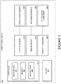
- Figure 1 illustrates a block diagram of a sanitization system, according to an example implementation.
- Figure 1 shows a sanitization system 100 for a space.
- the sanitization system 100 includes a controller 102 and a plurality of UV light sources, sensor devices, and movable components.
- the sanitization system 100 can be a computing system that includes one or more computing devices, such as the controller 102.
- the controller 102 can be a central controller of the sanitization system 100, and can interact with one or more additional computing devices to perform functions.
- the controller 102 includes processor(s) 104, a memory 106, and instructions 108.
- the processor(s) 104 may be general-purpose processors or special purpose processors (e.g., digital signal processors, application specific integrated circuits, etc.). Processor(s) 104 are configured to execute the instructions 108 stored in the memory 106 to provide the functionality of the controller 102 and related systems and methods described herein.
- the memory 106 may include or take the form of one or more computer-readable storage media that can be read or accessed by processor(s) 104.
- the computer-readable storage media can include volatile and/or non-volatile storage components, such as optical, magnetic, organic or other memory or disc storage, which can be integrated in whole or in part with processor(s) 104.
- memory 106 can be implemented using a single physical device (e.g., one optical, magnetic, organic or other memory or disc storage unit), while in other examples, memory 106 can be implemented using two or more physical devices.
- the memory 106 thus is a non-transitory computer readable storage medium, and the instructions 108 are stored thereon.
- the instructions 108 include computer executable code.
- the controller 102 may be configured to control aspects of the sanitization system in accordance with the instructions 108.
- the plurality of UV light sources, sensor devices and movable components includes a UV light source 112, a sensor device 114, and a movable component 116.
- the UV light source 112, the sensor device 114, and the movable component 116 may be integrated within a single device, or may be separate devices in communication with one another or with the controller 102.
- the plurality of UV light sources, sensor devices and movable components further includes an n-th UV light source 118, an n-th sensor device 120, and an n-th movable component 122.
- Each UV light source may be a light emitting device that emits light in the UV spectrum (e.g., about 100-400 nm).
- each UV light source may include one or more of a UV lamp, a UV light emitting diode (LED), or a UV laser.
- Each motion sensor device includes a sensor configured to track positions of one or more objects.
- each motion sensor device may include a proximity sensor, an infrared (IR) tracking sensor, an image capture device (e.g., a camera), a light detection and ranging (LIDAR) device, or another device capable of tracking positions of individuals in the space.
- Each movable component includes one or more of a switch, a servo, an actuator, an aperture, or another device configured to cause the UV light source to adjust a direction, beam angle, or beam spread of UV light emitted by the UV light source.
- the controller 102 can determine a desired light profile for UV light emitted from a respective UV light source, and can control a respective movable component to cause the respective UV light to emit light using the desired light profile.
- the controller 102 may track one or more exposure parameters (e.g., total time exposed to UV light or total UV light exposure level) for individual users across each respective UV light zone.
- a server 124 may be used for storing exposure parameter values for each user and characteristics of UV light emission in each UV light zone.
- the controller 102 may access this information to determine control instructions for respective UV light sources in the sanitization system 100. In this manner, for example, the controller 102 can control the n-th UV light source 118 based on UV light exposure of an individual.
- the controller 102 can manage UV light exposure levels based on a proximity of two or more individuals in the space. For example, if the two or more individuals are within a threshold distance of one another, the controller 102 can cause a UV light source to emit UV light between the two or more individuals.
- the controller 102 may determine a desired light profile to avoid each of the individuals, to avoid a particular individual based on a type of the particular individual, or to expose each individual to UV light in order to disinfect each individual and a proximate region between the two or more individuals.
- UV light sources may be included in the space.
- a controller may by dedicated to each UV light source or sensor device.
- the controller 102 may be a computing device within the server 124, or may be directly connected to one or both of a motion sensor device and a UV light source.
- the sanitization system 100 includes a UV light source (e.g., the UV light source 112) configured to emit UV light, a sensor device (e.g., the sensor device 114) configured to sense positions of a plurality of individuals within the space, and a controller (e.g., the controller 102) in communication with the UV light source and the sensor device.
- the controller is configured to monitor the positions of the plurality of individuals.
- the controller is further configured to determine, based on the positions of the plurality of individuals, that two or more individuals are less than a threshold distance from each other.
- the controller is further configured to, in response to determining that the two or more individuals are less than a threshold distance from each other, control the UV light source to emit UV light towards a proximate region between the two or more individuals.
- Other functionality of sanitization systems are described below with respect to Figures 2A-5 .
- the sanitization system 100, the controller 102, or portions thereof are configured to carry out this functionality, either individually or in conjunction with other devices or systems. Further details of sanitizing a space using UV light are provided below with respect to Figures 2A-5 .
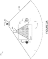
- Figure 2A illustrates a first context of operating a sanitization system in an environment, according to an example implementation.
- Figure 2 shows a top view of a sanitization system 200 that includes a UV light source 202, a sensor device 204, and a controller (not shown).
- the UV light source 202 is configured to emit UV light towards specified portions of the environment.
- the UV light can be emitted at a UV light level (e.g., a brightness level or power level of emitted UV light).
- the sensor device 204 is configured to sense positions of individuals in the environment.
- the sensor device can be an image capture device configured to capture images within a field of view 206. The images can be used for identifying different individuals.
- the sensor device 204 may include other sensors, such as IR sensors, LIDAR devices, proximity sensors, or other devices configured for detecting positions and/or movement of one or more individuals.
- Figure 2A shows a first individual 208 and a second individual 210.
- the sensor device 204 generates data used for determining positions of the first individual 208 and the second individual 210.
- the controller compares a distance between the first individual 208 and the second individual 210 to a threshold distance 212 to determine whether to emit UV light between the first individual 208 and the second individual 210. In Figure 2A , the distance is less than the threshold distance 212.
- the controller causes the UV light source 202 to emit UV light towards a proximate region 213 between the first individual 208 and the second individual 210.
- the proximate region 213 is an area in the environment that separates the first individual 208 from the second individual 210.
- the controller causes the UV light source 202 to emit UV light in accordance with a light profile 214 in order to cover at least a portion of the proximate region 213.
- the light profile 214 may be determined based on the positions of the first individual 208, the second individual 210, and may further be based on a position of the UV light source 202 in order to direct UV light towards at least a portion of the proximate region 213.
- Causing the UV light source 202 to emit UV light in accordance with the light profile 214 may include using a movable component (e.g., the movable component 116) to adjust a direction and/or a spread of a beam of UV light emitted from the UV light source 202.
- the light profile 214 is directed between the first individual 208 and the second individual 210 based on a first context.
- the controller may determine that both the first individual 208 and the second individual 210 are designated as a first type of individual that is expected to remain in the space for an extended period of time (e.g., more than two hours). Based on determining that both the first individual 208 and the second individual 210 are classified as the first type of individual, the controller may determine the light profile 214 such that UV light is directed away from both individuals while also covering at least a portion of the proximate region 213. In another example first context, the controller may determine the light profile 214 such that the UV light source 202 only emits light between individuals.
- the sanitization system determines an exposure parameter value for each individual.
- the exposure parameter value may be an amount of time that an individual is exposed to UV light, a total exposure level, or another parameter for quantifying how much UV light emitted toward the individual.
- the exposure parameter value may be compared to a threshold value to determine how to control the UV light source 202.
- the threshold value can be set based on a Threshold Limit Value for UV exposure (e.g., a value lower than the Threshold Limit Value).
- the threshold value may be determined based on one or more characteristics of the UV light source 202.
- the Threshold Limit Value may vary depending on the wavelength or range of wavelengths of UV light emitted by the UV light source 202, and the threshold value may be set based on the wavelength or range of wavelengths of UV light emitted by the UV light source 202. Accordingly, the controller may cause the UV light source 202 to (i) emit UV light towards the proximate region 213 and to emit light away from the first individual 208 and the second individual 210 based on one or more both of the first individual 208 and the second individual 210 having an exposure parameter value above the threshold value.
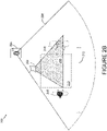
- Figure 2B illustrates a second context of operating a sanitization system in an environment, according to an example implementation.
- the controller causes the UV light source 202 to emit UV light in accordance with a light profile 216.
- the light profile 216 differs from the light profile 214 because the light profile 216 does not cover the first individual 208, but does cover at least a portion of the second individual 210.
- the first individual 208 is classified as a first type of individual and the second individual 210 is classified as a second type of individual.
- the first type of individual is expected to remain in the space for an extended period of time.
- the first type of individual may be resident of the space or work within the space.
- the controller sets the light profile 216 to omit the first individual 208 such that the first individual is exposed to UV light more gradually.
- the second individual 210 is expected to remain in the space for less time and may bring pathogens from outside the space into the space. Accordingly, the controller sets the light profile 216 such that the second individual 210 is exposed to UV light more rapidly and in order to disinfect the second individual 210.
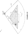
- Figure 2C illustrates a third context of operating a sanitization system in an environment, according to an example implementation.
- the controller causes the UV light source 202 to emit UV light in accordance with a light profile 281.
- the light profile 218 differs from the light profile 214 and the light profile 216 because the light profile 218 covers both the first individual 208 and the second individual 210.
- both the first individual 208 and the second individual 210 are classified as the second type of individual.
- the controller sets the light profile 218 such that both the first individual 208 and the second individual 210 are exposed to UV light relatively rapidly and in order to disinfect the first individual 208 and the second individual 210.
- the controller may determine that the exposure parameter value for both individuals is below the threshold level, and responsively set the light profile 218 to cover the first individual 208 and the second individual 210.
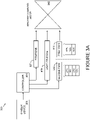
- Figure 3A illustrates a sanitization system training a machine learning model, according to an example implementation.
- Figure 3A shows a sanitization system 300 training a machine learning model to output desired light profiles.
- the sanitization system 300 includes a sensor device 302 and a controller 304.
- the controller is configured to receive data from the sensor device 302 and to generate a plurality of light profiles 308.
- each light profile may be set by the controller 304 as depicted in Figures 2A-2C .
- the controller is further configured to categorize each individual based on the data from the sensor device 302, and to track exposure parameter values (e.g., total exposure levels) for each user.
- exposure parameter values e.g., total exposure levels
- the controller 304 has categorized a plurality of individuals into a first type 312 and a second type 310. Because the first type 312 is expected to remain in a space for an extended period of time, the light profiles 308 are generated to emit UV light away from individuals of the first type 312. Accordingly, the controller 304 may train the machine learning model 306 using only data relating to exposure parameter levels of the first type 312.
- the controller 304 uses a plurality of positions 307 of individuals sensed by the sensor device 302 when UV light is emitted, the light profiles 308 used when UV light is emitted, and total exposure levels (e.g., a total exposure levels relative to a threshold level) for individuals of the first type 312 to train the machine learning model 306.
- total exposure levels e.g., a total exposure levels relative to a threshold level
- data from both the first type 312 of individual and the second type 310 of individual can be used for training the machine learning model 306.
- the machine learning model 306 can be a supervised model, such as a decision tree or support vector machine, an unsupervised model, such as a neural network, or another type of machine learning model configured to take in multiple inputs and to output a single output.
- a supervised model such as a decision tree or support vector machine
- an unsupervised model such as a neural network
- another type of machine learning model configured to take in multiple inputs and to output a single output.
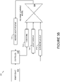
- Figure 3B illustrates the sanitization system 300 applying the machine learning model to an input, according to an example implementation.
- Figure 3B shows the controller 304, having already trained the machine learning model 306, providing positions 313 of two or more individuals, a default light profile 314, and exposure levels 316 of each of the two or more individuals. Data corresponding to the exposure levels 316 may also indicate a type of individual associated with each exposure level. Similarly, data corresponding to the positions 313 may also indicate a type of individual at each position.
- the machine learning model generates a desired light profile 318 based on the inputs. For example, the machine learning model 306 may automatically determine how much UV light to emit towards each individual and to a proximate region between the individuals based on the inputs.
- Figure 4 illustrates a sanitization system operating in an environment having a plurality of UV light zones, according to an example implementation.
- Figure 4 shows a space 400 that includes a UV light source 402, a second UV light source 404, a third UV light source 406, and a fourth UV light source 408.
- the space 400 further includes a first sensor device 410 and a second sensor device 412.
- the UV light sources and the sensor are part of a sanitization system that includes a controller (not shown).
- the sanitization system is configured to monitor positions of individuals in the space 400 using the sensor devices, and to emit UV light using the UV light sources based at least in part on the positions of the individuals.
- a server may store data that represents positions of each individual in the space 400, characteristics of different UV lights sources, and exposure parameter values for each individual.
- the controller of the sanitization system can use this information to control each UV light source in the environment.
- a plurality of individuals are shown interacting within the environment.
- a first type of individual in the plurality of individuals may be an employee of one or more businesses associated with the space 400
- a second type of individual may be a patron the one or more businesses.
- the second type of individual may approach the first type of individual for goods or services. Because the first type of individual is expect to remain within the space 400 for the majority of a workday, and because several individuals of the second type may approach throughout the workday, the first type of individual has more opportunities to be exposed to UV light.
- the UV light source 402 is proximate to a first individual 414 and a second individual 416.
- the first individual 414 is the first type of individual and the second individual 416 is the second type of individual.
- the sanitization system uses the first sensor device 410 to determine positions of the first individual 414 and the second individual 416.
- the first sensor device 410 may include an image capture device with a field of view that covers the first individual 414 and the second individual 416, and the controller may use facial recognition techniques to track movements and positions of the individuals.
- the first sensor device may generate data (e.g., image data) used to track movements of the individuals.
- the first sensor device 410 may alternatively include an IR tracking sensor, a LIDAR device, or another device capable of tracking positions of individuals the space 400.
- the controller of the sanitization system determines that the first individual 414 and the second individual 416 are within a threshold distance 418 (e.g., 6 feet) of each other, and responsively causes the UV light source 402 to emit UV light in accordance with a first light profile 420.
- the first light profile 420 covers a proximate region between the first individual 414 and the second individual 416, and also covers at least a portion of the second individual 416.
- the first light profile 420 is determined based on the first individual 414 being classified as the first type of individual and the second individual 416 being classified as the second type individual.
- the first light profile 420 gives the second individual 416 a dose of UV light while disinfecting the proximate region between the first individual 414 and the second individual 416.
- the second UV light source 404 is proximate to a third individual 422 and a fourth individual 424.
- the third individual 422 is the first type of individual and the fourth individual 424 is the second type of individual.
- the sanitization system uses the first sensor device 410 to determine positions of the third individual 422 and the fourth individual 424.
- the controller of the sanitization system determines that the third individual 422 and the fourth individual 424 are within a threshold distance 426 (e.g., 6 feet) of each other, and responsively causes the second UV light source 404 to emit UV light in accordance with a second light profile 428.
- the second light profile 428 covers a proximate region between the third individual 422and the fourth individual 424, and also is directed away from both the third individual 422and the fourth individual 424.
- the second light profile 428 is determined based on the third individual 422 being classified as the first type of individual and the fourth individual 424 being classified as the second type individual.
- the second light profile 428 is determined based on an exposure parameter level of the fourth individual 424 being greater than a threshold value. Accordingly, the second UV light source 404 is controlled to disinfect the proximate region between the third individual 422 and the fourth individual 424 without providing the fourth individual 424 a dose of UV light.
- the third UV light source 406 is proximate to a fifth individual 432 and a sixth individual 434. Both the fifth individual 432 and the sixth individual 434 are the second type of individual.
- the sanitization system uses the first sensor device 410 to determine positions of the fifth individual 432 and the sixth individual 434.
- the controller of the sanitization system determines that the fifth individual 432 and the sixth individual 434 are within a threshold distance 436 (e.g., 6 feet) of each other, and responsively causes the third UV light source 406 to emit UV light in accordance with a third light profile 438.
- the third light profile 438 covers a proximate region between the fifth individual 432 and the sixth individual 434, and also covers at least a portion of the fifth individual 432 and the sixth individual 434.
- the third light profile 438 is determined based on the fifth individual 432 and the sixth individual 434 being classified as the second type individual.
- the third light profile 438 is determined based on an exposure parameter level of the fifth individual 432 and the sixth individual 434 being less than a threshold value. Accordingly, the third UV light source 406 is controlled to disinfect the proximate region between the fifth individual 432 and the sixth individual 434 while also providing the fifth individual 432 and the sixth individual 434 a dose of UV light.
- Figure 4 shows that proximate regions are disinfected when two or more individuals are less than a threshold distance from one another.
- the sanitization system may accomplish this in part by monitoring predetermined interaction locations within the space 400.
- the space 400 includes a predetermined interaction location 437, which is a counter separating individuals of the first type from individuals of the second type. Controlling the UV light source 402 and the second UV light source 404 may be performed based on monitoring the predetermined interaction location 437.
- the first sensor device 410 may have a restricted field of view that focuses on areas surrounding the predetermined interaction location 437.
- the space 400 includes a predetermined interaction location 440, which is a table separating two or more individuals of the second type from one another. Other predetermined interaction locations may be dispersed throughout the space and monitored to determine when individuals are less than a threshold distance from one another.
- the sanitization system may disinfect the space 400 in other contexts as well.
- the sanitization system may operate in a first mode for disinfecting proximate regions between individuals and a second mode for disinfecting relatively high-traffic areas of the space 400.
- the sanitization system may disinfect UV light zones that each correspond to a queue, hallway, doorway, or another area of the space 400 where human traffic is expected.
- a seventh individual 444 is in a UV light zone 442 corresponding to a lavatory hallway. As the seventh individual 444 moves through the lavatory hallway within the UV light zone 442, the second sensor device 412 senses movements of the seventh individual 444.
- the second sensor device 412 may include an image capture device with a field of view that covers the UV light zone 442, and may generate data for use in tracking movements of the seventh individual 444.
- the controller may reduce a UV light level of the fourth UV light source 408 or otherwise alter how the fourth UV light source 408 emits UV light based on exposure parameter values of individuals in the UV light zone 442. In this manner, individuals of the first type may continue to intermittently receive doses of UV light when they enter high-traffic areas of the space 400.
- a single feature of a sanitization system (e.g., the controller or the first sensor device 410) can be associated with multiple different portions of the space 400.
- a single controller is described with respect to Figure 4
- a plurality of controllers can be used within the sanitization system.
- each UV light source or motion sensor device may correspond to a different controller, and each controller may interact with one another or with a server in order to control UV light levels within the space 400.
- Figure 4 shows a particular arrangement of an interior of a building, other arrangements are possible, and similar sanitization systems may be implemented in other places, such as in a commercial aircraft, in a train, in a bus, or in an outdoor venue.
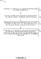
- Figure 5 illustrates a flowchart of a method 500 for sanitizing a space (e.g., the space 400), according to an example implementation.
- the method 500 shown in Figure 5 presents an example of a method that could be used with the sanitization system 100 or with components of thereof.
- the functions described with respect to Figure 5 may be supplemented by, replaced by, or combined with functions described above with respect to Figures 2A-4 .
- devices or systems may be used or configured to perform logical functions presented in Figure 5 .
- components of the devices and/or systems may be configured to perform the functions such that the components are actually configured and structured (with hardware and/or software) to enable such performance.
- components of the devices and/or systems may be arranged to be adapted to, capable of, or suited for performing the functions, such as when operated in a specific manner.
- Method 500 may include one or more operations, functions, or actions as illustrated by one or more of blocks 502-508. Although the blocks are illustrated in a sequential order, these blocks may also be performed in parallel, and/or in a different order than those described herein. Also, the various blocks may be combined into fewer blocks, divided into additional blocks, and/or removed based upon the desired implementation.
- each block or portions of each block may represent a module, a segment, or a portion of program code, which includes one or more instructions executable by a processor for implementing specific logical functions or steps in the process.
- the program code may be stored on any type of computer readable medium or data storage, for example, such as a storage device including a disk or hard drive. Further, the program code can be encoded on a computer-readable storage media in a machine-readable format, or on other non-transitory media or articles of manufacture.
- the computer readable medium may include non-transitory computer readable medium or memory, for example, such as computer-readable media that stores data for short periods of time like register memory, processor cache and Random Access Memory (RAM).
- the computer readable medium may also include non-transitory media, such as secondary or persistent long term storage, like read only memory (ROM), optical or magnetic disks, compact-disc read only memory (CD-ROM), for example.
- the computer readable media may also be any other volatile or non-volatile storage systems.
- the computer readable medium may be considered a tangible computer readable storage medium, for example.
- each block or portions of each block in Figure 5 may represent circuitry that is wired to perform the specific logical functions in the process.
- Alternative implementations are included within the scope of the examples of the present disclosure in which functions may be executed out of order from that shown or discussed, including substantially concurrent or in reverse order, depending on the functionality involved, as would be understood by those reasonably skilled in the art.
- the method 500 includes receiving, by a controller 102 of a sanitization system 100, sensor data from a sensor device 114.
- the method 500 includes monitoring, by the controller 102 based on the sensor data, positions of a plurality of individuals within the space 400.
- the plurality of individuals may include a first individual 414 and a second individual 416.
- the controller 102 may perform facial recognition techniques, object detection techniques, pixelwise color thresholding, or other techniques for determining positions of each individual.
- the method 500 includes determining, by the controller 102 based on the positions of the plurality of individuals, that two or more individuals are less than a threshold distance (e.g., the threshold distance 418) from each other.
- a threshold distance e.g., the threshold distance 4128
- the positions can be represented as numerical coordinates, and distance can be calculated between the coordinates.
- the method 500 includes, in response to determining that the two or more individuals are less than a threshold distance from each other, controlling, by the controller 102, a UV light source 402 to emit UV light towards a proximate region (e.g., the proximate region 213) between the two or more individuals.
- a proximate region e.g., the proximate region 213 between the two or more individuals.
- the proximate region may be a space defined by edges corresponding to coordinates of the positions of the two or more individuals.
- the method 500 further includes classifying each individual of the plurality of individuals as a type of individual.
- a first type of individual is expected to remain in the space for a specified timeframe (e.g., two or more hours), and a second type of individual is not expected to remain in the space for the specified timeframe.
- Classifying each individual as a type of individual may include comparing one or more features (e.g., facial features of each individual or identifying markers on a uniform of each individual) to a database of features to determine whether the features match a record of an individual designated as the first type of individual.
- the method 500 further includes determine that a respective individual of the two or more individuals is classified as the first type of individual.
- controlling the UV light source 402 to emit UV light towards the proximate region between the two or more individuals includes controlling the UV light source 112 based on determining that the respective individual is classified as the first type of individual. For example, based on determining that the respective individual is classified as the first type of individual, the method includes 500 controlling the UV light source 402 to emit UV light to avoid the respective individual based on determining that the respective individual is classified as the first type of individual. For example, this may be performed as shown in Figure 2B and Figure 4 .
- the method 500 further includes determining an exposure level of each individual classified as the first type of individual, training a machine learning model 306 using the exposure level of each individual classified as the first type of individual over a plurality of time cycles, and receiving from the machine learning model 306, a desired light profile 318 for controlling the UV light source 402. For example, this may be performed as described above with respect to Figures 3A and 3B .
- controlling the UV light source 402 to emit UV light towards the proximate region between the two or more individuals includes controlling the UV light source 402 based on the desired light profile 318.
- the method 500 further includes determining a traffic level of individuals classified as the second type of individual.
- controlling the UV light source 402 to emit UV light towards the proximate region between the two or more individuals includes controlling the UV light source 402 based on the traffic level.
- the traffic level may be a number of individuals that enter the space 400 within a given timeframe (e.g., one hour).
- controlling the UV light source 402 may be performed based on determining that the traffic level exceeds a threshold traffic level, and reduce a UV light level of the UV light source 402 based on determining that the traffic level exceeds the threshold traffic level.
- the method 500 further includes determining an expected total exposure level for individuals classified as the first type of individual based on the traffic level, and determining a desired UV light level for the UV light source 402 based on the expected total exposure level for the individuals classified as the first type of individual.
- controlling the UV light source 402 to emit UV light towards the proximate region between the two or more individuals includes controlling the UV light source 402 reducing a UV light level of the UV light source 402 from a first UV light level to the desired UV light level.
- reducing the UV light level of the UV light source 402 from the first UV light level to the desired UV light level includes providing an instruction for the individuals classified as the first type of individual.
- the instruction may include an instruction to maintain a larger distance from other individuals in the space 400 or to apply additional protective items to avoid exposure to pathogens from other individuals in the space 400.
- the method 500 includes controlling the UV light source 402 to emit UV light towards one or more individuals classified as the second type of individual and to not emit UV light towards one or more individuals classified as the first type of individual. For example, this may be performed as shown in Figure 2B .
- the method 500 further includes tracking a total exposure level for each of the plurality of individuals.
- controlling the UV light source 402 to emit UV light towards the proximate region between the two or more individuals includes controlling the UV light source 402 to emit UV light based on the total exposure level of each of the two or more individuals. For example, this may be performed as described above with respect to Figure 4 .
- the space 400 includes a plurality of predetermined interaction locations for individuals within the space 400, and the plurality of predetermined interaction locations include the proximate region between the two or more individuals.
- the plurality of predetermined interaction locations may be configured as shown in Figure 4 .
- controlling the UV light source 402 to emit UV light towards the proximate region between the two or more individuals includes controlling the UV light source 402 identifying a predetermined interaction location (e.g., the predetermined interaction location 437) from the plurality of predetermined interaction locations that is between the two or more individuals, and setting the predetermined interaction location as the proximate region between the two or more individuals.
- the sanitization system 100 may more consistently detect contexts for emitting UV light between two or more individuals.
- the systems and methods described herein provide a framework for sanitizing a space while maintaining exposure parameter levels of individuals below a threshold level.
- sanitization systems are described that effectively disinfect visitors to a space while also protecting residents or workers within a space from pathogens. This allows for a space to be reliably disinfected throughout an extended period of time.
- system(s), device(s), and method(s) disclosed herein include a variety of components, features, and functionalities. It should be understood that the various examples of the system(s), device(s), and method(s) disclosed herein may include any of the components, features, and functionalities of any of the other examples of the system(s), device(s), and method(s) disclosed herein in any combination or any sub-combination, and all of such possibilities are intended to be within the scope of the disclosure.
Landscapes
- Health & Medical Sciences (AREA)
- Life Sciences & Earth Sciences (AREA)
- General Health & Medical Sciences (AREA)
- Epidemiology (AREA)
- Animal Behavior & Ethology (AREA)
- Public Health (AREA)
- Veterinary Medicine (AREA)
- Engineering & Computer Science (AREA)
- Theoretical Computer Science (AREA)
- Physics & Mathematics (AREA)
- Software Systems (AREA)
- Mathematical Physics (AREA)
- Evolutionary Computation (AREA)
- Artificial Intelligence (AREA)
- Data Mining & Analysis (AREA)
- Computing Systems (AREA)
- General Engineering & Computer Science (AREA)
- General Physics & Mathematics (AREA)
- Computer Vision & Pattern Recognition (AREA)
- Medical Informatics (AREA)
- Biomedical Technology (AREA)
- Biophysics (AREA)
- Computational Linguistics (AREA)
- Molecular Biology (AREA)
- Disinfection, Sterilisation Or Deodorisation Of Air (AREA)
- Circuit Arrangement For Electric Light Sources In General (AREA)
- Length Measuring Devices By Optical Means (AREA)
- Apparatus For Disinfection Or Sterilisation (AREA)
Applications Claiming Priority (1)
| Application Number | Priority Date | Filing Date | Title |
|---|---|---|---|
| US202163183649P | 2021-05-04 | 2021-05-04 |
Publications (1)
| Publication Number | Publication Date |
|---|---|
| EP4085938A1 true EP4085938A1 (de) | 2022-11-09 |
Family
ID=80978953
Family Applications (1)
| Application Number | Title | Priority Date | Filing Date |
|---|---|---|---|
| EP22164829.8A Pending EP4085938A1 (de) | 2021-05-04 | 2022-03-28 | Systeme und verfahren zur desinfektion von nahen bereichen zwischen personen mit ultraviolettem licht |
Country Status (4)
| Country | Link |
|---|---|
| US (1) | US12539341B2 (de) |
| EP (1) | EP4085938A1 (de) |
| JP (1) | JP2022187982A (de) |
| CN (1) | CN115282303A (de) |
Citations (2)
| Publication number | Priority date | Publication date | Assignee | Title |
|---|---|---|---|---|
| US20170246331A1 (en) * | 2016-02-25 | 2017-08-31 | Ralph Birchard Lloyd | System and Method for Disinfecting an Occupied Area Using Germicidal Radiation Based on Eye Protection Worn by Persons in the Area |
| US10893990B1 (en) * | 2020-04-09 | 2021-01-19 | PetAirapy, LLC | Method and apparatus for treating an inside volume of a mobile vehicle |
Family Cites Families (60)
| Publication number | Priority date | Publication date | Assignee | Title |
|---|---|---|---|---|
| US5483127A (en) | 1994-01-19 | 1996-01-09 | Don Widmayer & Associates, Inc. | Variable arc electronic ballast with continuous cathode heating |
| JPH0831585A (ja) | 1994-07-15 | 1996-02-02 | Ushio Inc | 誘電体バリア放電装置 |
| DE19824423A1 (de) | 1998-05-30 | 1999-12-02 | Hansa Metallwerke Ag | Schaltungsanordnung zum Betreiben einer UV-Lampe in einem Entkeimungsreaktor |
| JP3881183B2 (ja) | 2001-03-13 | 2007-02-14 | 株式会社荏原製作所 | 紫外線照射装置 |
| US6877248B1 (en) | 2004-03-05 | 2005-04-12 | Gregory N. Cross | Clothes dryer with ultraviolet light |
| US7871518B2 (en) | 2006-03-27 | 2011-01-18 | Dbg Group Investments, Llc | Apparatus for treating wash water supplied |
| EP2257791A4 (de) | 2008-03-03 | 2011-11-02 | Vioguard Corp | Uv-behandlungsgerät |
| US8339069B2 (en) | 2008-04-14 | 2012-12-25 | Digital Lumens Incorporated | Power management unit with power metering |
| US8552664B2 (en) | 2008-04-14 | 2013-10-08 | Digital Lumens Incorporated | Power management unit with ballast interface |
| US8543249B2 (en) | 2008-04-14 | 2013-09-24 | Digital Lumens Incorporated | Power management unit with modular sensor bus |
| US8368321B2 (en) | 2008-04-14 | 2013-02-05 | Digital Lumens Incorporated | Power management unit with rules-based power consumption management |
| US8138690B2 (en) | 2008-04-14 | 2012-03-20 | Digital Lumens Incorporated | LED-based lighting methods, apparatus, and systems employing LED light bars, occupancy sensing, local state machine, and meter circuit |
| US8805550B2 (en) | 2008-04-14 | 2014-08-12 | Digital Lumens Incorporated | Power management unit with power source arbitration |
| US8232670B2 (en) | 2009-01-30 | 2012-07-31 | The Boeing Company | Localized utility power system for aircraft |
| US8954170B2 (en) | 2009-04-14 | 2015-02-10 | Digital Lumens Incorporated | Power management unit with multi-input arbitration |
| US8593135B2 (en) | 2009-04-14 | 2013-11-26 | Digital Lumens Incorporated | Low-cost power measurement circuit |
| CN102021782B (zh) | 2009-09-09 | 2012-05-23 | 建兴电子科技股份有限公司 | 具消毒杀菌功能的洗衣球装置 |
| CA2777014A1 (en) | 2009-10-16 | 2011-04-21 | Hospira, Inc. | Ultraviolet sterilization system |
| US11154629B2 (en) * | 2011-04-15 | 2021-10-26 | Steriliz, Llc | Room sterilization method and system |
| EA028682B1 (ru) | 2011-04-15 | 2017-12-29 | Самюэль Ричард Трапани | Система для стерилизации помещений |
| US9165756B2 (en) * | 2011-06-08 | 2015-10-20 | Xenex Disinfection Services, Llc | Ultraviolet discharge lamp apparatuses with one or more reflectors |
| WO2014036217A2 (en) | 2012-08-29 | 2014-03-06 | Mag Aerospace Industries, Inc. | Aircraft galley and lavatory disinfection |
| CA2931403C (en) | 2012-12-06 | 2020-03-31 | Xenex Disinfection Services, Llc. | Systems which determine operating parameters and disinfection schedules for germicidal devices and germicidal lamp apparatuses including lens systems |
| US8877124B2 (en) * | 2013-01-31 | 2014-11-04 | Robert Bergman | Apparatus, system, and method for evaluating and adjusting the effectiveness of ultraviolet light disinfection of areas |
| US20140266695A1 (en) | 2013-03-15 | 2014-09-18 | Covidien Lp | System and method for disinfecting and charging a sensor |
| US10145055B1 (en) | 2014-06-03 | 2018-12-04 | Cliff Shirp Enterprises, LLC | Apparatus and methods for ultraviolet light treatment of laundry |
| US9700072B2 (en) | 2014-09-30 | 2017-07-11 | Sensor Electronic Technology, Inc. | Movable ultraviolet radiation source |
| US9606001B2 (en) | 2015-01-07 | 2017-03-28 | The Boeing Company | Systems and methods for monitoring ultraviolet light exposure in an environment |
| US9623133B2 (en) | 2015-01-30 | 2017-04-18 | The Boeing Company | Lavatory disinfection system |
| US9662410B2 (en) | 2015-02-27 | 2017-05-30 | The Boeing Company | Systems and methods for sanitizing a tray table |
| US9855353B1 (en) | 2015-04-28 | 2018-01-02 | Brian Michael Stacy | Rapid disinfection system for ambulance patient cabin |
| US10752358B2 (en) | 2015-10-19 | 2020-08-25 | The Boeing Company | Systems and methods for refreshing passenger garments onboard an aircraft |
| US10793291B2 (en) | 2016-03-31 | 2020-10-06 | The Boeing Company | Systems and methods for cleaning interior portions of a vehicle |
| US10407887B2 (en) | 2016-03-31 | 2019-09-10 | The Boeing Company | Systems and methods for automatically cleaning a lavatory floor |
| US10065740B2 (en) | 2016-03-31 | 2018-09-04 | The Boeing Company | Systems and methods for cleaning a lavatory floor |
| US9783974B1 (en) | 2016-08-09 | 2017-10-10 | The Boeing Company | Fluid removal systems and methods |
| US10662627B2 (en) | 2016-08-16 | 2020-05-26 | The Boeing Company | Ultraviolet light treating water dispensation systems and methods |
| US10272169B2 (en) | 2016-08-19 | 2019-04-30 | The Boeing Company | Ozone ventilation systems and methods |
| US9993571B2 (en) | 2016-08-24 | 2018-06-12 | The Boeing Company | Multi-wavelength ultraviolet light sanitizing systems and methods |
| EP3290058A1 (de) * | 2016-09-02 | 2018-03-07 | BrainLit AB | Lichtsteuersystem und ein verfahren zur belichtung eines teilbereichs eines raumes mit licht in einem vorgegebenen spektralbereich bei einer vorgegebenen schwellenstärke |
| US10918748B2 (en) | 2016-09-08 | 2021-02-16 | The Boeing Company | Deployable ultraviolet light sanitizing systems and methods |
| US10232954B2 (en) | 2016-09-21 | 2019-03-19 | The Boeing Company | Apparatuses and methods for reducing ozone creation from ultraviolet (UV) light |
| US10264931B2 (en) | 2016-09-23 | 2019-04-23 | The Boeing Company | Hand drying systems and methods |
| US10624979B2 (en) | 2017-06-26 | 2020-04-21 | The Boeing Company | Systems and methods for operating a light system |
| US10228622B2 (en) | 2017-06-26 | 2019-03-12 | The Boeing Company | Systems and methods for operating a light system |
| US10301806B2 (en) | 2017-06-26 | 2019-05-28 | The Boeing Company | Disinfection systems and methods for operating a light system |
| US10130727B1 (en) | 2017-06-26 | 2018-11-20 | The Boeing Company | Systems and methods for operating a light system |
| US10702618B2 (en) | 2017-06-26 | 2020-07-07 | The Boeing Company | Disinfection systems and methods for operating a light system |
| GB201715458D0 (en) * | 2017-07-28 | 2017-11-08 | Airbus Sas | Aircraft Cabin Disinfection System |
| US10449895B2 (en) * | 2018-03-20 | 2019-10-22 | Rockwell Collins, Inc. | Object tracking illumination system |
| JP7103870B2 (ja) * | 2018-06-28 | 2022-07-20 | トヨタホーム株式会社 | 空気清浄設備の制御システム |
| JP7133777B2 (ja) * | 2018-08-24 | 2022-09-09 | パナソニックIpマネジメント株式会社 | 空間浄化システム、及び、空間浄化方法 |
| US10960094B1 (en) * | 2020-06-16 | 2021-03-30 | Innovative Technologies | Disinfection system |
| US20220008575A1 (en) * | 2020-07-10 | 2022-01-13 | Sood, Seth, Khatri & Chaudhary Llc | Ultraviolet pathogen disinfection system |
| WO2022039957A1 (en) * | 2020-08-18 | 2022-02-24 | UVDevelopment LLC | Automatic far-uv environmental sanitization |
| JP2022036703A (ja) * | 2020-08-24 | 2022-03-08 | 東芝ライテック株式会社 | 紫外線照射システム |
| US12005834B2 (en) * | 2020-09-23 | 2024-06-11 | Toyota Motor North America, Inc. | Autonomous seat sanitizing system for a vehicle |
| JP7181483B2 (ja) * | 2021-03-31 | 2022-12-01 | ダイキン工業株式会社 | 紫外線照射装置 |
| JP2023030486A (ja) * | 2021-08-23 | 2023-03-08 | トヨタ自動車株式会社 | 消毒デバイス及び消毒システム |
| JP2023087276A (ja) * | 2021-12-13 | 2023-06-23 | コニカミノルタ株式会社 | 消毒装置システム |
-
2022
- 2022-03-28 EP EP22164829.8A patent/EP4085938A1/de active Pending
- 2022-03-30 US US17/709,086 patent/US12539341B2/en active Active
- 2022-04-25 CN CN202210438518.8A patent/CN115282303A/zh active Pending
- 2022-04-27 JP JP2022072986A patent/JP2022187982A/ja active Pending
Patent Citations (2)
| Publication number | Priority date | Publication date | Assignee | Title |
|---|---|---|---|---|
| US20170246331A1 (en) * | 2016-02-25 | 2017-08-31 | Ralph Birchard Lloyd | System and Method for Disinfecting an Occupied Area Using Germicidal Radiation Based on Eye Protection Worn by Persons in the Area |
| US10893990B1 (en) * | 2020-04-09 | 2021-01-19 | PetAirapy, LLC | Method and apparatus for treating an inside volume of a mobile vehicle |
Also Published As
| Publication number | Publication date |
|---|---|
| JP2022187982A (ja) | 2022-12-20 |
| US20220354976A1 (en) | 2022-11-10 |
| US12539341B2 (en) | 2026-02-03 |
| CN115282303A (zh) | 2022-11-04 |
Similar Documents
| Publication | Publication Date | Title |
|---|---|---|
| US11620894B2 (en) | Surveillance system and method for predicting patient falls using motion feature patterns | |
| JP7696955B2 (ja) | 長期間の継続的な動物行動モニタリング | |
| US20250177593A1 (en) | Systems and methods for autonomous sterilization | |
| US20220027618A1 (en) | Method of searching data to identify images of an object captured by a camera system | |
| US20210349462A1 (en) | Ultraviolet end effector | |
| US20200254125A1 (en) | System and Method for Disinfecting an Occupied Environment Using Direction Controlled Germicidal Radiation | |
| US8400266B2 (en) | Monitoring device, monitoring method, and monitoring program | |
| RU2016149891A (ru) | Оптическая система отслеживания для автоматизации элементов парка развлечений | |
| US9569670B2 (en) | Destination and duration of stay determination in a geographically bounded area | |
| JP2019087250A (ja) | オブジェクト履歴関連付けにおけるシステムと方法 | |
| US20210370505A1 (en) | Method of detecting human and/or animal motion and performing mobile disinfection | |
| CN119731711A (zh) | 使用嵌入在连接的照明系统中的传感器进行预测性队列管理的系统和方法 | |
| EP4085938A1 (de) | Systeme und verfahren zur desinfektion von nahen bereichen zwischen personen mit ultraviolettem licht | |
| EP4085936A1 (de) | Systeme und verfahren zur desinfektion von personen mit ultraviolettem licht | |
| JP7800134B2 (ja) | 情報処理プログラム、情報処理方法および情報処理装置 | |
| EP2698041B1 (de) | Steuersystem für raumbeleuchtung | |
| CN116368543A (zh) | 使用运动传感器监控社交距离的系统和方法 | |
| Rico et al. | Chameleon: Adaptive sensor intelligence for smart buildings | |
| US20160338177A1 (en) | Lighting control system and lighting control method | |
| KR20210079823A (ko) | 전자 장치 및 이의 제어 방법 | |
| US20250009922A1 (en) | Systems and methods for targeted sanitization | |
| US11995968B2 (en) | Systems, devices, and methods to electronically lure people at a building | |
| WO2022043040A1 (en) | Systems and methods for detecting and tracing individuals exhibiting symptoms of infections | |
| US20250062013A1 (en) | Artificial intelligence enhanced cleaning | |
| WO2026023299A1 (ja) | 殺菌装置、殺菌システム、および紫外線出力モジュール |
Legal Events
| Date | Code | Title | Description |
|---|---|---|---|
| PUAI | Public reference made under article 153(3) epc to a published international application that has entered the european phase |
Free format text: ORIGINAL CODE: 0009012 |
|
| STAA | Information on the status of an ep patent application or granted ep patent |
Free format text: STATUS: THE APPLICATION HAS BEEN PUBLISHED |
|
| AK | Designated contracting states |
Kind code of ref document: A1 Designated state(s): AL AT BE BG CH CY CZ DE DK EE ES FI FR GB GR HR HU IE IS IT LI LT LU LV MC MK MT NL NO PL PT RO RS SE SI SK SM TR |
|
| RAP3 | Party data changed (applicant data changed or rights of an application transferred) |
Owner name: THE BOEING COMPANY |
|
| STAA | Information on the status of an ep patent application or granted ep patent |
Free format text: STATUS: REQUEST FOR EXAMINATION WAS MADE |
|
| 17P | Request for examination filed |
Effective date: 20230426 |
|
| RBV | Designated contracting states (corrected) |
Designated state(s): AL AT BE BG CH CY CZ DE DK EE ES FI FR GB GR HR HU IE IS IT LI LT LU LV MC MK MT NL NO PL PT RO RS SE SI SK SM TR |
|
| STAA | Information on the status of an ep patent application or granted ep patent |
Free format text: STATUS: EXAMINATION IS IN PROGRESS |
|
| 17Q | First examination report despatched |
Effective date: 20241104 |