EP4085960A1 - Système et procédé de commande d'humidification pour un appareil de thérapie de ventilation - Google Patents
Système et procédé de commande d'humidification pour un appareil de thérapie de ventilation Download PDFInfo
- Publication number
- EP4085960A1 EP4085960A1 EP20909786.4A EP20909786A EP4085960A1 EP 4085960 A1 EP4085960 A1 EP 4085960A1 EP 20909786 A EP20909786 A EP 20909786A EP 4085960 A1 EP4085960 A1 EP 4085960A1
- Authority
- EP
- European Patent Office
- Prior art keywords
- heating
- temperature
- air
- fan
- flow rate
- Prior art date
- Legal status (The legal status is an assumption and is not a legal conclusion. Google has not performed a legal analysis and makes no representation as to the accuracy of the status listed.)
- Granted
Links
Images


Classifications
-
- A—HUMAN NECESSITIES
- A61—MEDICAL OR VETERINARY SCIENCE; HYGIENE
- A61M—DEVICES FOR INTRODUCING MEDIA INTO, OR ONTO, THE BODY; DEVICES FOR TRANSDUCING BODY MEDIA OR FOR TAKING MEDIA FROM THE BODY; DEVICES FOR PRODUCING OR ENDING SLEEP OR STUPOR
- A61M16/00—Devices for influencing the respiratory system of patients by gas treatment, e.g. ventilators; Tracheal tubes
- A61M16/10—Preparation of respiratory gases or vapours
- A61M16/14—Preparation of respiratory gases or vapours by mixing different fluids, one of them being in a liquid phase
- A61M16/16—Devices to humidify the respiration air
- A61M16/162—Water-reservoir filling system, e.g. automatic
-
- A—HUMAN NECESSITIES
- A61—MEDICAL OR VETERINARY SCIENCE; HYGIENE
- A61M—DEVICES FOR INTRODUCING MEDIA INTO, OR ONTO, THE BODY; DEVICES FOR TRANSDUCING BODY MEDIA OR FOR TAKING MEDIA FROM THE BODY; DEVICES FOR PRODUCING OR ENDING SLEEP OR STUPOR
- A61M16/00—Devices for influencing the respiratory system of patients by gas treatment, e.g. ventilators; Tracheal tubes
- A61M16/10—Preparation of respiratory gases or vapours
- A61M16/1075—Preparation of respiratory gases or vapours by influencing the temperature
- A61M16/1095—Preparation of respiratory gases or vapours by influencing the temperature in the connecting tubes
-
- A—HUMAN NECESSITIES
- A61—MEDICAL OR VETERINARY SCIENCE; HYGIENE
- A61M—DEVICES FOR INTRODUCING MEDIA INTO, OR ONTO, THE BODY; DEVICES FOR TRANSDUCING BODY MEDIA OR FOR TAKING MEDIA FROM THE BODY; DEVICES FOR PRODUCING OR ENDING SLEEP OR STUPOR
- A61M16/00—Devices for influencing the respiratory system of patients by gas treatment, e.g. ventilators; Tracheal tubes
- A61M16/021—Devices for influencing the respiratory system of patients by gas treatment, e.g. ventilators; Tracheal tubes operated by electrical means
- A61M16/022—Control means therefor
- A61M16/024—Control means therefor including calculation means, e.g. using a processor
-
- A—HUMAN NECESSITIES
- A61—MEDICAL OR VETERINARY SCIENCE; HYGIENE
- A61M—DEVICES FOR INTRODUCING MEDIA INTO, OR ONTO, THE BODY; DEVICES FOR TRANSDUCING BODY MEDIA OR FOR TAKING MEDIA FROM THE BODY; DEVICES FOR PRODUCING OR ENDING SLEEP OR STUPOR
- A61M16/00—Devices for influencing the respiratory system of patients by gas treatment, e.g. ventilators; Tracheal tubes
- A61M16/10—Preparation of respiratory gases or vapours
- A61M16/14—Preparation of respiratory gases or vapours by mixing different fluids, one of them being in a liquid phase
- A61M16/16—Devices to humidify the respiration air
-
- A—HUMAN NECESSITIES
- A61—MEDICAL OR VETERINARY SCIENCE; HYGIENE
- A61M—DEVICES FOR INTRODUCING MEDIA INTO, OR ONTO, THE BODY; DEVICES FOR TRANSDUCING BODY MEDIA OR FOR TAKING MEDIA FROM THE BODY; DEVICES FOR PRODUCING OR ENDING SLEEP OR STUPOR
- A61M16/00—Devices for influencing the respiratory system of patients by gas treatment, e.g. ventilators; Tracheal tubes
- A61M16/0057—Pumps therefor
- A61M16/0066—Blowers or centrifugal pumps
-
- A—HUMAN NECESSITIES
- A61—MEDICAL OR VETERINARY SCIENCE; HYGIENE
- A61M—DEVICES FOR INTRODUCING MEDIA INTO, OR ONTO, THE BODY; DEVICES FOR TRANSDUCING BODY MEDIA OR FOR TAKING MEDIA FROM THE BODY; DEVICES FOR PRODUCING OR ENDING SLEEP OR STUPOR
- A61M16/00—Devices for influencing the respiratory system of patients by gas treatment, e.g. ventilators; Tracheal tubes
- A61M16/06—Respiratory or anaesthetic masks
- A61M16/0666—Nasal cannulas or tubing
- A61M16/0672—Nasal cannula assemblies for oxygen therapy
-
- A—HUMAN NECESSITIES
- A61—MEDICAL OR VETERINARY SCIENCE; HYGIENE
- A61M—DEVICES FOR INTRODUCING MEDIA INTO, OR ONTO, THE BODY; DEVICES FOR TRANSDUCING BODY MEDIA OR FOR TAKING MEDIA FROM THE BODY; DEVICES FOR PRODUCING OR ENDING SLEEP OR STUPOR
- A61M16/00—Devices for influencing the respiratory system of patients by gas treatment, e.g. ventilators; Tracheal tubes
- A61M16/10—Preparation of respiratory gases or vapours
- A61M16/1075—Preparation of respiratory gases or vapours by influencing the temperature
- A61M16/109—Preparation of respiratory gases or vapours by influencing the temperature the humidifying liquid or the beneficial agent
-
- A—HUMAN NECESSITIES
- A61—MEDICAL OR VETERINARY SCIENCE; HYGIENE
- A61M—DEVICES FOR INTRODUCING MEDIA INTO, OR ONTO, THE BODY; DEVICES FOR TRANSDUCING BODY MEDIA OR FOR TAKING MEDIA FROM THE BODY; DEVICES FOR PRODUCING OR ENDING SLEEP OR STUPOR
- A61M16/00—Devices for influencing the respiratory system of patients by gas treatment, e.g. ventilators; Tracheal tubes
- A61M16/10—Preparation of respiratory gases or vapours
- A61M16/14—Preparation of respiratory gases or vapours by mixing different fluids, one of them being in a liquid phase
- A61M16/16—Devices to humidify the respiration air
- A61M16/161—Devices to humidify the respiration air with means for measuring the humidity
-
- A—HUMAN NECESSITIES
- A61—MEDICAL OR VETERINARY SCIENCE; HYGIENE
- A61M—DEVICES FOR INTRODUCING MEDIA INTO, OR ONTO, THE BODY; DEVICES FOR TRANSDUCING BODY MEDIA OR FOR TAKING MEDIA FROM THE BODY; DEVICES FOR PRODUCING OR ENDING SLEEP OR STUPOR
- A61M2205/00—General characteristics of the apparatus
- A61M2205/33—Controlling, regulating or measuring
- A61M2205/3331—Pressure; Flow
- A61M2205/3334—Measuring or controlling the flow rate
-
- A—HUMAN NECESSITIES
- A61—MEDICAL OR VETERINARY SCIENCE; HYGIENE
- A61M—DEVICES FOR INTRODUCING MEDIA INTO, OR ONTO, THE BODY; DEVICES FOR TRANSDUCING BODY MEDIA OR FOR TAKING MEDIA FROM THE BODY; DEVICES FOR PRODUCING OR ENDING SLEEP OR STUPOR
- A61M2205/00—General characteristics of the apparatus
- A61M2205/33—Controlling, regulating or measuring
- A61M2205/3368—Temperature
-
- A—HUMAN NECESSITIES
- A61—MEDICAL OR VETERINARY SCIENCE; HYGIENE
- A61M—DEVICES FOR INTRODUCING MEDIA INTO, OR ONTO, THE BODY; DEVICES FOR TRANSDUCING BODY MEDIA OR FOR TAKING MEDIA FROM THE BODY; DEVICES FOR PRODUCING OR ENDING SLEEP OR STUPOR
- A61M2205/00—General characteristics of the apparatus
- A61M2205/33—Controlling, regulating or measuring
- A61M2205/3379—Masses, volumes, levels of fluids in reservoirs, flow rates
- A61M2205/3393—Masses, volumes, levels of fluids in reservoirs, flow rates by weighing the reservoir
-
- A—HUMAN NECESSITIES
- A61—MEDICAL OR VETERINARY SCIENCE; HYGIENE
- A61M—DEVICES FOR INTRODUCING MEDIA INTO, OR ONTO, THE BODY; DEVICES FOR TRANSDUCING BODY MEDIA OR FOR TAKING MEDIA FROM THE BODY; DEVICES FOR PRODUCING OR ENDING SLEEP OR STUPOR
- A61M2209/00—Ancillary equipment
- A61M2209/04—Tools for specific apparatus
- A61M2209/045—Tools for specific apparatus for filling, e.g. for filling reservoirs
Definitions
- the present application relates to the technical field of electronic apparatus, and more particularly, to a humidification control system and method for a ventilation therapy apparatus.
- the high-flow-rate warming humidifier is a new respiration treatment apparatus that is capable of humidifying high-flow-rate gas mixed with oxygen and delivering it to the patient.
- the apparatus may be set according to the actual needs of the patient, to output air of the corresponding flow rate, or to warm and humidify it to the appropriate temperature and humidity after mixing oxygen from the exterior with the ambient air, and delivering it to the nasal cavity of the patient.
- the humidifier cannot evaporate sufficient water vapor immediately.
- the patient is not prompted to wear the apparatus until the warming and humidification of the humidifier is close to a stable state after a pre-heating process of the started humidifier.
- the patient may use the humidifier in an environment beyond the reasonable environmental condition, and therefore the patient may wear the nasal oxygen cannula before the pre-heating process is completed, which causes the humidity and the temperature of the air inhaled by the patient are not suitable, which not only bring no effect of the treatment, but also may cause damage to the respiratory tract of the patient.
- the present application provides a humidifier gas-flow control system, to solve the above problems.
- the first aspect of the present application provides a humidification control system of a ventilation-treatment apparatus, wherein the system includes a main ventilation-treatment-apparatus body, a respiration humidifier, a heating pipeline and a nasal oxygen cannula;
- the first controller includes an evaporation-rate analyzing module, a flow-rate controlling module and a warming-and-humidification controlling module, and the warming-and-humidification controlling module is configured for, according to the target flow rate, the target humidity, the ambient-air humidity and the ambient-air temperature, determining a heating power of the heating plate, and controlling the heating plate to operate at the heating power;
- the operation of the first controller of, according to the target flow rate, the target humidity, the ambient-air humidity and the ambient-air temperature, determining the heating power of the heating plate particularly includes:
- the heating controlling module of the heating pipeline controls the heating power of the heating pipeline by:
- the operation of, by the heating controlling module of the heating pipeline, according to the air flow rate inputted by the fan, the temperature of the first mixed gas flow, the temperature of the second mixed gas flow and the target temperature preset by the user, determining the heating power of the heating pipeline particularly includes:
- the first controller includes a first determining module, and the first determining module is configured for, when the water evaporation rate in the water tank maintains stable, determining whether a current air flow rate of the fan is equal to the target flow rate preset by the user; and when the current air flow rate of the fan is equal to the target flow rate, the first controller controls the heating plate to continue operating at a current heating power and controlling the fan to continue operating at the current air flow rate at the same time.
- the first controller further includes a second determining module, and the second determining module is configured for, when the current air flow rate of the fan is less than the target flow rate, determining whether the current heating power of the heating plate is a maximum power and being maintained for a second time interval, and when the current heating power of the heating plate is the maximum power and being maintained for the second time interval, the first controller controls the heating plate to continue operating at the current heating power, and simultaneously controls the fan to continue operating at the current air flow rate.
- the second determining module is configured for, when the current air flow rate of the fan is less than the target flow rate, determining whether the current heating power of the heating plate is a maximum power and being maintained for a second time interval, and when the current heating power of the heating plate is the maximum power and being maintained for the second time interval, the first controller controls the heating plate to continue operating at the current heating power, and simultaneously controls the fan to continue operating at the current air flow rate.
- the first controller re-determines the heating power of the heating plate, and simultaneously, according to a water evaporation rate of evaporation when the heating plate operates at the re-determined heating power of the heating plate, adjusts the air flow rate inputted by the fan, till the water evaporation rate maintains stable, to input into the heating pipeline the mixed gas flow obtained by mixing the water vapor and the air, wherein the relative humidity of the mixed gas flow is the target humidity.
- the system further includes a fan-gas-inlet temperature-and-humidity sensor, and the fan-gas-inlet temperature-and-humidity sensor is configured for measuring a temperature and a humidity at a gas inlet of the fan, to obtain the ambient-air temperature and the ambient-air humidity.
- the second aspect of the present application provides a humidification controlling method of a ventilation-treatment apparatus, wherein the method is applied to a humidification control system of a ventilation-treatment apparatus, the humidification control system of a ventilation-treatment apparatus includes a heating plate, a water tank, a fan and a heating pipeline, and the method includes:
- the Step S2 includes: according to a first time interval, monitoring a water-tank gas temperature and a heating-plate temperature at a water-tank gas inlet, and according to the water-tank gas temperature and the heating-plate temperature, determining the current water evaporation rate in the water tank.
- Step S1 includes:
- the Step S4 includes: according to a heat dissipation rate of the heating pipeline at a current ambient-air temperature and the temperature of the first mixed gas flow at the gas inlet of the heating pipeline, determining the temperature of the second mixed gas flow at the gas outlet of the heating pipeline.
- Step S5 includes:
- the method further includes:
- the present application has the following advantages:
- the present application at the pre-heating phase, firstly, by acquiring the ambient-air temperature, the ambient-air humidity and the air temperature inside the water tank, and, by the first controller, receiving the ambient-air temperature, the ambient-air humidity, the gas temperature inside the water tank, and the target flow rate, the target humidity and the target temperature that are preset by the user, and processing them, the present application performs the controlling with the outputted temperature and humidity as the target, and does not perform the controlling with the flow rate as the target, to maintain the outputted gas flow at the suitable humidity at any time.
- the temperature and the humidity of the gas flow inhaled by the patient may be the target temperature and the target humidity, and when the patient wears the apparatus in advance, the patient will not feel dry.
- the humidifier When the humidifier is operating in a condition beyond the environmental condition of normal operation, it may be determined that the preset output may not be reached, and, when the preset output may not be reached, a gas flow of a lower flow rate and a higher humidity may be supplied, rather than a gas flow of a higher flow rate and a lower humidity, which enables the patient to wear more comfortably.
- the present applicant may ensure that the patient, when wearing the nasal oxygen cannula in advance before the ending of the pre-heating or when the outputting capability of the humidifier is insufficient, may still inhale a gas flow of the suitable temperature and humidity. Accordingly, the present application ensures thoroughly that all of the gas flows inhaled by the patient are the mixed gas flow that satisfies the target temperature and the target humidity, which ensures the comfortableness of the patient.
- the primary function of a high-flow-rate warming humidifier is to implement warming and humidification. when the temperature and the humidity of gas outputted by the humidifier are not suitable, the patient inhales the gas may feel very uncomfortable, and even cause damage to his respiratory system.
- the outputted gas should be a gas not less than 33mg/L (equivalent to that the temperature is 37°C and the relative humidity is 75%).
- Article 6 provides that the humidifier is expected to be used for patients of upper-respiratory-tract bypassing, the range and the setting of the regulation on the gas flow rate should be described when the condition that the humidifying system outputs the minimum 33mg/L is satisfied.
- the humidifiers disposed in the related art are pre-heated for a period of time at the beginning of the operation.
- the humidifier outputs the gas at the preset flow rate, and when the gas is heated to a preset temperature or a temperature lower than the preset temperature by a certain temperature, it is prompted that the pre-heating is ended and the patient may wear the apparatus.
- the preset temperature is 37°C
- the prompting is made when the actual temperature reaches 34°C (the absolute humidity of saturated steam is 37.5mg/L and exceeds 33mg/L).
- the humidifier when the humidifier operates in an environmental condition that goes beyond the environmental condition explicitly written in the specification, when the humidifier detects that the temperature and the humidification effect may not reach the demand of the preset temperature of 37°C and humidity of 33mg/L after operating for a period of time, it may merely send an alarm that the target temperature may not be reached, to prompt the patient that the humidifier may not reach the target of output in the current environmental condition. Accordingly, the patient has to make a choice. The patient may feel uncomfortable when he chooses to inhale the presently outputted gas flow, and the therapy may not reach an excellent effect. when the patient chooses not to inhale the presently outputted gas flow, which means that he gives up the therapy, therefore, and the purpose of therapy may not be achieved.
- the humidifiers disposed in the related art due to the power limitation of the humidifiers themselves, the humidifiers may not reach the standard of output of 33mg/L in all conditions. Therefore, the specifications of all of the humidifiers make clear to the ranges of the temperature and the humidity of the environments for normal use, to instruct doctors or patients to use them in reasonable environmental conditions.
- the humidifiers disposed in the related art in the particular process of usage, there is not always a physician alongside for instruction, or the environment where the humidifiers are located and used may not enable the humidifiers to output a gas not less than 33mg/L (equivalent to that the temperature is 37°C and the relative humidity is 75%).
- the humidifier does not stop operating, or is adaptively adjusted according to the environment where it is located, whereby the outputted gas is still inhaled by the patient, which makes the patient feel extremely uncomfortable, or causes damage to the respiratory system of the patient.
- the humidifiers disposed in the related art may output a gas not less than 33mg/L (equivalent to that the temperature is 37°C and the relative humidity is 75%), when the gas of a temperature of 37°C and a relative humidity of 75% is inhaled into the body of the patient, the patient may also feel extremely uncomfortable.
- the outputted gas flow reaches 37°C and a relative humidity of 100%, or, in other words, the water vapor contained in the outputted gas is 43.81mg/L, it may ensure that the patient may feel comfortable after inhaling the gas.
- the present application provides a humidification control system of a ventilation-treatment apparatus shown in FIG. 1 .
- the system includes a ventilation-treatment-apparatus main body, a respiration humidifier, a heating pipeline and a nasal oxygen cannula.
- the ventilation-treatment-apparatus main body includes a fan and a first controller.
- the respiration humidifier includes a water tank, a heating plate, a water-tank-gas-inlet temperature sensor, and a heating-plate temperature sensor.
- the water in the water tank of the respiration humidifier may be from a water bottle.
- the water bottle is configured to supply water to the respiration humidifier.
- the water may be a medical liquid, for example, a mixed liquid added with some liquid medicines or a water added with sufficient oxygen, and may also just be water.
- the respiration humidifier is configured to convert the water dripped from the water bottle into water vapor, whereby the relative humidity of the gas flow flowing through the respiration humidifier reaches 100%.
- the gas flow flowing out of the respiration humidifier of the relative humidity of 100% is inputted into the heating pipeline.
- the heating pipeline is configured to preserve the temperature of the gas flow flowing through its interior, to enable the temperature of the gas flow inputted into the nasal oxygen cannula by the heating pipeline to be the target temperature.
- the fan and the water tank are encapsulated in a housing.
- a gas outlet of the fan is connected to a gas inlet of the water tank.
- a gas outlet of the water tank is connected to a gas inlet of the heating pipeline.
- the water outlet of the water bottle is connected to the water inlet of the water tank.
- a gas outlet of the heating pipeline is connected to an input opening of the nasal oxygen cannula.
- the water-tank-gas-inlet temperature sensor is disposed at the gas inlet of the water tank, and is configured to detect the air temperature of the air inputted via the gas inlet of the water tank.
- the heating-plate temperature sensor is disposed at the heating plate, and is configured to detect the temperature of the heating plate.
- the water-tank-gas-inlet temperature sensor and the heating-plate temperature sensor are communicatively connected to the first controller.
- the first controller is configured for receiving an ambient-air temperature and an ambient-air humidity (the ambient-air temperature and the ambient-air humidity may be obtained by measurement by the fan-gas-inlet temperature-and-humidity sensor, and the fan-gas-inlet temperature-and-humidity sensor may be disposed at the gas inlet of the fan; furthermore, the ambient-air temperature and the ambient-air humidity may also be inputted by the user), a water-tank gas temperature of the water-tank-gas-inlet temperature sensor, a heating-plate temperature transmitted by the heating-plate temperature sensor, and a target humidity and a target flow rate that are preset by a user, to determine an air flow rate inputted by the fan, so that a current relative humidity of a first mixed gas flow obtained by mixing a water vapor in the water tank and air inputted by the fan is the target humidity.
- the target humidity may be 88%
- the mode of generating the mixed gas flow with relative humidity as the target humidity in the water tank is as follows:
- the first controller includes an evaporation-rate analyzing module, a flow-rate controlling module and a warming-and-humidification controlling module.
- the warming-and-humidification controlling module is configured for, according to the target flow rate, the target humidity, the ambient-air humidity and the ambient-air temperature, determining a heating power of the heating plate, and controlling the heating plate to operate at the heating power.
- the water in the water tank is converted into the water vapor because the heating plate heats the water, and the water is evaporated after absorbing the heat to form the water vapor.
- the fan inputs the ambient air into the water tank, and the ambient air and the water vapor are mixed, to form the mixed gas flow.
- the amount of the gas flow inhaled by the patient is usually set particularly according to the situation of the patient itself, and the target flow rate required to be inhaled by the patient may be determined accordingly.
- the target temperature and the target humidity of the target flow rate may also be determined.
- the target temperature is 37°C
- the target humidity is a relative humidity of 100%.
- the temperature and the humidity of the air inputted by the fan are the atmospheric temperature and the atmospheric humidity, and the air inputted by the fan itself has a certain temperature and a certain humidity accordingly.
- it is required to add the water vapor into the air with a certain temperature and a certain humidity, thereby forming the gas flow which relative humidity is 100%.
- the atmospheric temperature and the atmospheric humidity may be obtained by measurement by the fan-gas-inlet temperature-and-humidity sensor, and are referred to as the ambient-air temperature and the ambient-air humidity, respectively.
- the warming-and-humidification controlling module may determine the amount of the water required to be evaporated and the heat required to be absorbed by that amount of the water, and then the heating power of the heating plate may be determined, and control the heating plate to operate at the heating power.
- the heating by the heating plate relates to the issue of heating efficiency.
- the heating efficiency of the heating plate is closely related to the environment, therefore, the actual heating power of the heating plate is obtained in the following manner:
- the operation of the first controller of, according to the target flow rate, the target humidity, the ambient-air humidity and the ambient-air temperature, determining the heating power of the heating plate particularly includes:
- the ambient-air temperature is 20°C
- the ambient-air humidity is 20%
- the current absolute humidity is 3.45mg/L.
- the target temperature is 37°C
- the target relative humidity is 100%
- the target absolute humidity is 43.81mg/L.
- the temperature of the water is 20 °C, and the specific enthalpy of water is 83.86kJ/kg.
- the specific enthalpy of saturated steam at 37 °C is 2567.98kJ/kg. Accordingly, the heat required to be absorbed to convert water into water vapor is:
- the target flow rate required by the patient is 40L/min, i.e., 0.67L/s.
- the density of water vapor at 37°C is 0.4kg/m 3
- the actual heating power should be 95.5W.
- the evaporation-rate analyzing module is configured for, according to a first time interval, according to the water-tank gas temperature and the heating-plate temperature, determining a current water evaporation rate in the water tank.
- the water evaporation rate has relation with the atmospheric pressure, the wind speed and the temperature difference. Because the present application mainly focuses on the evaporation rate of the water in the water tank, merely the influence by the temperature difference on the water evaporation rate is taken into consideration. In the particular usage process, the influence on the water evaporation rate by factors such as the atmospheric pressure and the wind speed may be further taken into consideration according to actual situations.
- FIGS. 2 and 3 are a variation diagram of the water evaporation amount and a variation diagram of the temperature of the humidifier, respectively, in 40 minutes after a certain time of the operation of the humidifier.
- the humidifier and the connecting components are weighed one time for every 5 minutes, and the amount of the evaporated water is recorded.
- FIG. 2 it may be seen from FIG. 2 that, in the 20 minutes after the beginning of the operation of the humidifier, the water evaporation amount gradually increases for every 5 minutes, and from the time period of 25th-30th minutes the water evaporation amount reaches a stable state.
- the variation of the temperature of the humidifier is similar to that of the evaporation rate, which substantially reaches a stable state at the 15th minute.
- the heating by the heating plate increases the temperature of the air inside the water tank, and also influences the air temperature of the connection between the water tank and the fan to a certain extent.
- the vicinity of the pipeline ports connecting the water tank and the fan is influenced by the temperature increase of the air in the water tank to a certain extent, whereby when the air is passing through the connection between the water tank and the fan, the air is slightly heated, therefore, the temperature of the air entering the water tank and the temperature of the air entering the gas inlet of the fan are different.
- the fan-gas-inlet temperature-and-humidity sensor is disposed at the gas inlet of the fan, and is configured to detect the temperature and the humidity of the air entering the fan. Due to the temperature of the gas inlet of the fan and the temperature of the external environment are equal, the temperature and the humidity that are collected by the fan-gas-inlet temperature-and-humidity sensor are used as the ambient-air temperature and the ambient-air humidity. Subsequently, the air temperature at the gas inlet inside the water tank is measured by using the water-tank-gas-inlet temperature sensor.
- the flow-rate controlling module is configured for, according to the current water evaporation rate, adjusting the air flow rate inputted by the fan, so that the relative humidity of the mixed gas flow obtained by mixing the water vapor and the air is 100%, till the water evaporation rate in the water tank maintains stable.
- the temperature of the heating plate starts to increase from normal temperature, and the temperature gradually increases over time.
- the heating power of the heating plate and the stabilized temperature of the heating plate when the variation of the ambient-air temperature is excluded, which are basically correspond one to one. Therefore, the temperature of the heating plate gradually increases in a certain period of time (referred to as a heating-plate first phase) after the beginning of the heating, and after that, the temperature may be stable (the phase when the temperature is stable is referred to as a heating-plate second phase).
- a heating-plate first phase the phase when the temperature is stable is referred to as a heating-plate second phase.
- the temperature of the heating plate gradually increases, and, with the increasing of the temperature, the evaporation rate of the water also constantly changes; in other words, the water evaporation amount is also unstable.
- the relative humidity of the outputted mixed gas flow in the present application is 100%, it is required to adjust the amount of the air inputted by the fan according to the water evaporation amount, so that when the air inputted by the fan flows out of the gas outlet of the water tank, the relative humidity is 100%.
- the heating-plate first phase it is required to calculate the water evaporation rate periodically, thereby obtaining the water evaporation amount, and adjust the power of the fan according to the water evaporation amount, thereby changing the air amount inputted by the fan.
- the process of the water absorbing the heat and being converted into the water vapor is lagging as compared with the process of the temperature rising of the heating plate. Therefore, in the heating-plate first phase, in the process of the water absorbing the heat and being converted into the water vapor, the water evaporation rate is unstable, which phase is referred to as a water-evaporation first phase. In the heating-plate second phase, i.e., after the temperature of the heating plate being stable, the water evaporation rate is required to be divided into two phases, which are referred to as a water-evaporation second phase and a water evaporation third phase.
- the water-evaporation second phase refers to that, although the temperature of the heating plate is already stable, the water evaporation rate is still unstable.
- the water evaporation third phase is reached, i.e., the phase when the water evaporation rate is stable.
- All of the heating-plate first phase, the heating-plate second phase, the water-evaporation first phase, the water-evaporation second phase and the water evaporation third phase ensure that the relative humidity of the mixed gas flow obtained by mixing the water vapor and the air brought by the fan is 100%, which makes the patient feel comfortable to a certain extent after inhaling the gas flow.
- the relative humidity of 100% is insufficient, and it is also required to ensure that the temperature of the mixed gas flow is the target temperature.
- the target temperature is maintained by using the heating pipeline.
- the heating pipeline includes a heating-pipe-line-gas-inlet temperature sensor and a heating controlling module of the heating pipeline.
- the heating-pipe-line-gas-inlet temperature sensor is disposed at the gas inlet of the heating pipeline.
- the heating-pipe-line-gas-inlet temperature sensor is communicatively connected to the heating controlling module of the heating pipeline.
- the heating controlling module of the heating pipeline is configured for receiving a temperature of the first mixed gas flow at the gas inlet of the heating pipeline and a temperature of a second mixed gas flow at the gas outlet, to determine a currently required heating power of the heating pipeline, to adjust the heating pipeline to the currently required heating power, to maintain a temperature of a mixed gas flow obtained by mixing the water vapor transmitted via the heating pipeline to the nasal oxygen cannula and the air at a target temperature.
- the temperature of the first mixed gas flow is obtained by measurement by the heating-pipe-line-gas-inlet temperature sensor disposed at the gas inlet of the heating pipeline.
- the temperature of the second mixed gas flow may be obtained by measurement by a heating-pipeline-gas-outlet temperature sensor disposed at the gas outlet of the heating pipeline, and may also be obtained by calculation according to the temperature of the first mixed gas flow and the heat dissipation rate of the heating pipeline.
- the mixed gas flow outputted from the water tank is directly delivered to the nasal oxygen cannula via a common pipeline without heating or thermal insulation
- the temperature of the common pipeline is normal temperature but the temperature of the water vapor is higher
- the contacting between the water vapor and the common pipeline causes the water vapor to condensate, which reduces the humidity of the mixed gas flow, whereby the humidity of the gas flow inhaled by the patient is insufficient, and it may not ensure that the patient feels comfortable.
- the heat dissipates, which reduces the temperature.
- the degree of the decreasing of the temperature is closely related to the ambient-air temperature, and, therefore, the temperature of the mixed gas flow when it reaches the nasal oxygen cannula may not be ensured.
- the heating pipeline is configured to deliver the mixed gas flow.
- the target temperature of the mixed gas flow delivered in the delivering pipe is 37°C, and, in order to achieve that object, it is required to detect the temperature of the mixed gas flow at the gas inlet of the heating pipeline by using the heating-pipe-line-gas-inlet temperature sensor, detect the temperature of the mixed gas flow at the gas outlet of the heating pipeline by using the heating-pipeline-gas-outlet temperature sensor, and, according to the temperature difference between them and the target temperature, determine the heating power of the heating pipeline.
- the heating power of the heating pipeline is also uncertain; in other words, the heating power of the heating pipeline is required to be adjusted according to demands.
- the first controller transmits the target temperature and the air amount inputted by the fan to the heating controlling module of the heating pipeline in real time, and the heating controlling module of the heating pipeline, according to the temperature difference between the temperature of the mixed gas flow at the gas inlet of the heating pipeline and the temperature of the mixed gas flow at the gas outlet of the heating pipeline, the target temperature, and the air amount inputted by the fan, adjusts the heating power of the heating pipeline in real time.
- the heating controlling module of the heating pipeline controls the heating power of the heating pipeline by:
- the amount of the gas flow flowing through the heating pipeline also influences the degree of the thermal insulation of the gas flow by the heating pipeline.
- the operation of, by the heating controlling module of the heating pipeline, according to the air flow rate inputted by the fan, the temperature of the first mixed gas flow, the temperature of the second mixed gas flow and the target temperature preset by the user determining the heating power of the heating pipeline particularly includes:
- the evaporation rate that is finally stabilized is 8.6g per 5 minutes and, in average 1.72g per minute, which is 42.6Lwhen divided by 40.36mg/L.
- the humidifier may finally stably output a gas flow of a flow rate of 42.6L/min, a temperature of 37°C, and a humidity of 100%.
- the above process may ensure that the temperature of the mixed gas flow outputted from the nasal oxygen cannula is the target temperature, and the humidity of the mixed gas flow is the target humidity. According to particular situations of patients, there are requirements on the amount of the inhaled mixed gas flow, and therefore it is also required to determine whether the flow rate of the mixed gas flow reaches the target flow rate.
- the first controller includes a first determining module, and the first determining module is configured for, when the water evaporation rate in the water tank maintains stable, determining whether a current air flow rate of the fan is equal to the target flow rate preset by the user; and when the current air flow rate of the fan is equal to the target flow rate, the first controller controls the heating plate to continue operating at a current heating power, and controls the fan to continue operating at the current air flow rate at the same time.
- the humidifier gas-flow control system when the current air flow rate of the fan is the target flow rate, the humidifier gas-flow control system according to the present application reaches a stable state, and may output the mixed gas flow that satisfies the target flow rate, the target humidity and the target temperature, which may ensure the patient feels comfortable, and may ensure that the patient inhales a sufficient amount of the mixed gas flow.
- the first controller further includes a second determining module, and the second determining module is configured for, when the current air flow rate of the fan is less than the target flow rate, determining whether the current heating power of the heating plate is a maximum power and being maintained for a second time interval (the second time interval may be set according to particular situations, for example, 15 minutes and 20 minutes), and when the current heating power of the heating plate is the maximum power and being maintained for the second time interval, the first controller controls the heating plate to continue operating at the current heating power, and controlling the fan to continue operating at the current air flow rate at the same time.
- the second determining module is configured for, when the current air flow rate of the fan is less than the target flow rate, determining whether the current heating power of the heating plate is a maximum power and being maintained for a second time interval (the second time interval may be set according to particular situations, for example, 15 minutes and 20 minutes), and when the current heating power of the heating plate is the maximum power and being maintained for the second time interval, the first controller controls the heating plate to continue operating at the current
- the factors of the environment where the humidifier gas-flow control system is used may result in that the current amount of the mixed gas flow is less than the target flow rate, so it is required to determine whether the heating power of the heating plate at the moment is the maximum power of the heating plate.
- the flow rate of the mixed gas flow outputted currently by the humidifier gas-flow control system is already the maximum discharge that may be outputted in the current environment, therefore, only the temperature and the humidity of the mixed gas flow may be ensured, and the flow rate of the mixed gas flow may not be ensured.
- the patient is prompted that the target flow rate may not be outputted; for example, the target flow rate of 60L/min is set, but a flow rate of 55L/min is finally outputted.
- the humidifier does not reach the preset output, the patient may normally wear it, and may not feel uncomfortable due to insufficient humidity.
- the first controller re-determines the heating power of the heating plate, and at the same time, according to a water evaporation rate of evaporation when the heating plate operates at the re-determined heating power of the heating plate, adjusts the air flow rate inputted by the fan, till the water evaporation rate maintains stable, to input into the heating pipeline the mixed gas flow obtained by mixing the water vapor and the air, wherein the relative humidity of the mixed gas flow is the target humidity.
- the present application performs the controlling with the outputted temperature and humidity as the target, and does not perform the controlling with the flow rate as the target, to maintain the outputted gas flow at the suitable temperature and humidity at any time, and when the patient wears the apparatus in advance, the patient will not feel dry.
- the humidifier When the humidifier is operating in a condition beyond the environmental condition of normal operation, it may be determined that the preset output may not be reached, and, when the preset output may not be reached, a gas flow of a lower flow rate and a higher humidity may be supplied, rather than a gas flow of a higher flow rate and a lower humidity, which enables the patient to wear more comfortably.
- the present applicant may ensure that the patient wears the nasal oxygen cannula in advance before the ending of the pre-heating or when the outputting capability of the humidifier is insufficient, so that the patient may still inhale a gas flow of the suitable temperature and humidity. Accordingly, the present application ensures thoroughly that all of the gas flows inhaled by the patient are the mixed gas flow that satisfies the target temperature and the target humidity, which ensures comfort of the patient.
- the present application provides a humidification controlling method of a ventilation-treatment apparatus shown in FIGS. 4 and 5 .
- the method is applied to a humidification control system of a ventilation-treatment apparatus, the humidification control system of a ventilation-treatment apparatus includes a heating plate, a water tank, a fan and a heating pipeline, and the method includes:
- the Step S2 includes: according to a first time interval, monitoring a water-tank gas temperature and a heating-plate temperature at a water-tank gas inlet, and according to the water-tank gas temperature and the heating-plate temperature, determining the current water evaporation rate in the water tank.
- Step S1 includes:
- the Step S4 includes: according to a heat dissipation rate of the heating pipeline at a current ambient-air temperature and the temperature of the first mixed gas flow at the gas inlet of the heating pipeline, determining the temperature of the second mixed gas flow at the gas outlet of the heating pipeline.
- Step S5 includes:
- the method further includes:
- Each component embodiment of the present disclosure may be implemented by hardware, or by software modules that are operated on one or more processors, or by a combination thereof.
- a person skilled in the art should understand that some or all of the functions of some or all of the components of the calculating and processing apparatus according to the embodiments of the present disclosure may be implemented by using a microprocessor or a digital signal processor (DSP) in practice.
- DSP digital signal processor
- the present disclosure may also be implemented as apparatus or apparatus programs (for example, computer programs and computer program products) for implementing part of or the whole of the method described herein. Such programs for implementing the present disclosure may be stored in a computer-readable medium, or may be in the form of one or more signals. Such signals may be downloaded from an Internet website, or disposed on a carrier signal, or disposed in any other forms.
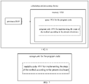
- FIG. 6 shows a calculating and processing apparatus that may implement the method according to the present disclosure.
- the calculating and processing apparatus traditionally includes a processor 1010 and a computer program product or computer-readable medium in the form of a memory 1020.
- the memory 1020 may be electronic memories such as flash memory, EEPROM (Electrically Erasable Programmable Read Only Memory), EPROM, hard disk or ROM.
- the memory 1020 has the storage space 1030 of the program code 1031 for implementing any steps of the above method.
- the storage space 1030 for program code may contain program codes 1031 for individually implementing each of the steps of the above method. Those program codes may be read from one or more computer program products or be written into the one or more computer program products.
- Those computer program products include program code carriers such as a hard disk, a compact disk (CD), a memory card or a floppy disk. Such computer program products are usually portable or fixed storage units as shown in FIG. 7 .
- the storage unit may have storage segments or storage spaces with similar arrangement to the memory 1020 of the calculating and processing apparatus in FIG. 6 .
- the program codes may, for example, be compressed in a suitable form.
- the storage unit contains a computer-readable code 1031', which may be read by a processor like 1010. When those codes are executed by the calculating and processing apparatus, the codes cause the calculating and processing apparatus to implement each of the steps of the method described above.
- any reference signs between parentheses should not be construed as limiting the claims.
- the word “include” does not exclude elements or steps that are not listed in the claims.
- the word “a” or “an” preceding an element does not exclude the existing of a plurality of such elements.
- the present disclosure may be implemented by means of hardware comprising several different elements and by means of a properly programmed computer. In unit claims that list several apparatuses, some of those apparatus may be embodied by the same item of hardware.
- the words first, second, third and so on do not denote any order. Those words may be interpreted as names.
Landscapes
- Health & Medical Sciences (AREA)
- Emergency Medicine (AREA)
- Pulmonology (AREA)
- Engineering & Computer Science (AREA)
- Anesthesiology (AREA)
- Biomedical Technology (AREA)
- Heart & Thoracic Surgery (AREA)
- Hematology (AREA)
- Life Sciences & Earth Sciences (AREA)
- Animal Behavior & Ethology (AREA)
- General Health & Medical Sciences (AREA)
- Public Health (AREA)
- Veterinary Medicine (AREA)
- Otolaryngology (AREA)
- Air Humidification (AREA)
- Air Conditioning Control Device (AREA)
Applications Claiming Priority (2)
| Application Number | Priority Date | Filing Date | Title |
|---|---|---|---|
| CN201911424720.XA CN111150917B (zh) | 2019-12-31 | 2019-12-31 | 一种通气治疗设备湿化控制系统和方法 |
| PCT/CN2020/136747 WO2021135942A1 (fr) | 2019-12-31 | 2020-12-16 | Système et procédé de commande d'humidification pour un appareil de thérapie de ventilation |
Publications (3)
| Publication Number | Publication Date |
|---|---|
| EP4085960A1 true EP4085960A1 (fr) | 2022-11-09 |
| EP4085960A4 EP4085960A4 (fr) | 2024-01-03 |
| EP4085960B1 EP4085960B1 (fr) | 2025-12-03 |
Family
ID=70560733
Family Applications (1)
| Application Number | Title | Priority Date | Filing Date |
|---|---|---|---|
| EP20909786.4A Active EP4085960B1 (fr) | 2019-12-31 | 2020-12-16 | Système et procédé de commande d'humidification pour un appareil de thérapie de ventilation |
Country Status (4)
| Country | Link |
|---|---|
| US (1) | US20230049982A1 (fr) |
| EP (1) | EP4085960B1 (fr) |
| CN (1) | CN111150917B (fr) |
| WO (1) | WO2021135942A1 (fr) |
Cited By (2)
| Publication number | Priority date | Publication date | Assignee | Title |
|---|---|---|---|---|
| EP4085960A4 (fr) * | 2019-12-31 | 2024-01-03 | BMC Medical Co., Ltd. | Système et procédé de commande d'humidification pour un appareil de thérapie de ventilation |
| US12520880B2 (en) | 2021-01-18 | 2026-01-13 | Altria Client Services Llc | Heat-not-burn (HNB) aerosol-generating devices including energy based heater control, and methods of controlling a heater |
Families Citing this family (15)
| Publication number | Priority date | Publication date | Assignee | Title |
|---|---|---|---|---|
| CN111617363A (zh) * | 2020-06-08 | 2020-09-04 | 山东科技大学 | 一种具有加湿恒温控制功能的湿化治疗仪及其控制方法 |
| CN111939421A (zh) * | 2020-07-24 | 2020-11-17 | 天津怡和嘉业医疗科技有限公司 | 通气治疗设备 |
| CN112181026A (zh) * | 2020-09-27 | 2021-01-05 | 湖南明康中锦医疗科技发展有限公司 | 一种湿化器温度输出控制系统和控制方法 |
| CN113082933B (zh) * | 2021-03-31 | 2023-08-22 | 珠海格力电器股份有限公司 | 一种制氧机 |
| US20240285893A1 (en) * | 2021-06-04 | 2024-08-29 | Fisher & Paykel Healthcare Limited | Improved respiratory support apparatus |
| CN114306866A (zh) * | 2021-12-29 | 2022-04-12 | 深圳普门科技股份有限公司 | 控制呼吸湿化仪的方法、装置、呼吸湿化仪及存储介质 |
| EP4547301B1 (fr) * | 2022-06-30 | 2025-12-03 | Koninklijke Philips N.V. | Commande du taux d'évaporation d'un humidificateur avec commande de puissance adaptative et procédé |
| CN116123726B (zh) * | 2022-12-13 | 2026-03-17 | 天津怡和嘉业医疗科技有限公司 | 温度控制方法、装置、通气设备及可读存储介质 |
| CN116212185A (zh) * | 2022-12-28 | 2023-06-06 | 深圳融昕医疗科技有限公司 | 呼吸机及其温度控制方法、主控设备 |
| CN116271400A (zh) * | 2023-01-09 | 2023-06-23 | 湖南明康中锦医疗科技股份有限公司 | 一种温湿度控制方法及控制系统与呼吸湿化治疗设备 |
| CN117042825B (zh) * | 2023-02-02 | 2026-04-17 | 泰利艾尔有限公司 | 呼吸治疗设备和方法 |
| CN117752910A (zh) * | 2023-11-27 | 2024-03-26 | 北京谊安健康科技有限公司 | 一种呼吸机的加湿加热调节方法、系统及呼吸机 |
| CN117563100B (zh) * | 2023-12-26 | 2024-10-22 | 深圳融昕医疗科技有限公司 | 呼吸设备的湿化值补偿装置、方法及呼吸设备 |
| CN117942479B (zh) * | 2023-12-29 | 2024-07-19 | 广州和普乐健康科技有限公司 | 湿化器恒温恒湿控制方法、系统以及医疗湿化输出装置 |
| CN120022496B (zh) * | 2025-02-26 | 2025-12-16 | 北京中关村水木医疗科技有限公司 | 医用湿化器及超温气体的预警方法 |
Family Cites Families (20)
| Publication number | Priority date | Publication date | Assignee | Title |
|---|---|---|---|---|
| CA2617287C (fr) * | 1997-06-17 | 2011-11-15 | Fisher & Paykel Healthcare Limited | Systeme d'humidification pour appareillage respiratoire |
| BR0013570B1 (pt) * | 1999-08-23 | 2009-01-13 | controlador de umidade. | |
| US6796550B2 (en) * | 2001-08-14 | 2004-09-28 | Hamilton Beach/Proctor-Silex, Inc. | Humidifier filter servicing and water level indicator |
| US7140367B2 (en) * | 2002-02-20 | 2006-11-28 | Fisher & Paykel Healtcare Limited | Conduit overheating detection system |
| US9802022B2 (en) * | 2008-03-06 | 2017-10-31 | Resmed Limited | Humidification of respiratory gases |
| ES2683235T3 (es) * | 2008-05-27 | 2018-09-25 | Fisher & Paykel Healthcare Limited | Control de temperatura de cámara humidificadora para un control preciso de la humedad |
| CA2784852C (fr) * | 2009-12-23 | 2018-02-27 | Fisher & Paykel Healthcare Limited | Dispositif de distribution de gaz humidifies et procedes de commande de celui-ci |
| US9314582B2 (en) * | 2010-11-23 | 2016-04-19 | Carefusion 2200, Inc. | Humidification system |
| WO2012100291A1 (fr) * | 2011-01-24 | 2012-08-02 | Resmed Limited | Humidificateur |
| JP6258873B2 (ja) * | 2012-02-24 | 2018-01-10 | コーニンクレッカ フィリップス エヌ ヴェKoninklijke Philips N.V. | 加湿を含む呼吸療法のためのレインアウト保護 |
| JP6543192B2 (ja) * | 2012-09-28 | 2019-07-10 | フィッシャー アンド ペイケル ヘルスケア リミテッド | 加湿呼吸装置制御 |
| US20150165146A1 (en) * | 2013-12-17 | 2015-06-18 | Bruce Bowman | Humidification system and positive airway pressure apparatus incorporating same |
| DE102014008625A1 (de) * | 2014-06-17 | 2015-12-17 | Drägerwerk AG & Co. KGaA | Vorrichtung und Verfahren zur Dosierung eines Narkosemittels in einen Gasstrom |
| CN105194782A (zh) * | 2014-06-25 | 2015-12-30 | 卓效医疗有限公司 | 微型加湿器 |
| US10596345B2 (en) * | 2014-12-31 | 2020-03-24 | Vapotherm, Inc. | Systems and methods for humidity control |
| CN105920715B (zh) * | 2016-06-30 | 2018-10-12 | 北京怡和嘉业医疗科技股份有限公司 | 加热湿化器以及加热湿化方法 |
| CN108245759A (zh) * | 2017-12-16 | 2018-07-06 | 湖南明康中锦医疗科技发展有限公司 | 呼吸湿化治疗仪温湿度输出控制系统及方法 |
| EP4306153B1 (fr) * | 2018-03-26 | 2026-04-29 | Fisher & Paykel Healthcare Limited | Chambre d'humidification |
| WO2019222159A1 (fr) * | 2018-05-14 | 2019-11-21 | Covidien Lp | Systèmes et procédés d'humidification par ventilation |
| CN111150917B (zh) * | 2019-12-31 | 2021-09-14 | 北京怡和嘉业医疗科技股份有限公司 | 一种通气治疗设备湿化控制系统和方法 |
-
2019
- 2019-12-31 CN CN201911424720.XA patent/CN111150917B/zh active Active
-
2020
- 2020-12-16 WO PCT/CN2020/136747 patent/WO2021135942A1/fr not_active Ceased
- 2020-12-16 EP EP20909786.4A patent/EP4085960B1/fr active Active
- 2020-12-16 US US17/790,134 patent/US20230049982A1/en active Pending
Cited By (2)
| Publication number | Priority date | Publication date | Assignee | Title |
|---|---|---|---|---|
| EP4085960A4 (fr) * | 2019-12-31 | 2024-01-03 | BMC Medical Co., Ltd. | Système et procédé de commande d'humidification pour un appareil de thérapie de ventilation |
| US12520880B2 (en) | 2021-01-18 | 2026-01-13 | Altria Client Services Llc | Heat-not-burn (HNB) aerosol-generating devices including energy based heater control, and methods of controlling a heater |
Also Published As
| Publication number | Publication date |
|---|---|
| CN111150917B (zh) | 2021-09-14 |
| WO2021135942A1 (fr) | 2021-07-08 |
| US20230049982A1 (en) | 2023-02-16 |
| EP4085960A4 (fr) | 2024-01-03 |
| CN111150917A (zh) | 2020-05-15 |
| EP4085960B1 (fr) | 2025-12-03 |
Similar Documents
| Publication | Publication Date | Title |
|---|---|---|
| EP4085960B1 (fr) | Système et procédé de commande d'humidification pour un appareil de thérapie de ventilation | |
| JP7562732B2 (ja) | 呼吸器加湿システム | |
| AU2023285700B2 (en) | Humidification breathing apparatus control | |
| US10426914B2 (en) | System and method for adjusting humidification during pressure support therapy | |
| AU2003227324B2 (en) | Respiratory gas humidifier system for a patient | |
| CN113425974B (zh) | 呼吸气体的湿化 | |
| JP2021098029A (ja) | 患者にガスを供給する装置 | |
| CN119746234A (zh) | 呼吸气体的湿化 | |
| RU2631185C2 (ru) | Система и способ определения целевой температуры средства взаимодействия с субъектом на основании базовой температуры | |
| EP3213787A1 (fr) | Système de distribution d'aérosol avec humidification | |
| US20220143356A1 (en) | Dew point sensor system, method for modulating a humidifier heater plate, and humidifier/medical device containing | |
| US20140060533A1 (en) | Methods and system for humidifier control using enthalpy-based calculation | |
| RU2587955C2 (ru) | Система и способ подачи увлажненной газовой смеси вентилируемому пациенту | |
| GB2446495A (en) | Respiratory humidify with threshold point controller system. |
Legal Events
| Date | Code | Title | Description |
|---|---|---|---|
| STAA | Information on the status of an ep patent application or granted ep patent |
Free format text: STATUS: THE INTERNATIONAL PUBLICATION HAS BEEN MADE |
|
| PUAI | Public reference made under article 153(3) epc to a published international application that has entered the european phase |
Free format text: ORIGINAL CODE: 0009012 |
|
| STAA | Information on the status of an ep patent application or granted ep patent |
Free format text: STATUS: REQUEST FOR EXAMINATION WAS MADE |
|
| 17P | Request for examination filed |
Effective date: 20220729 |
|
| AK | Designated contracting states |
Kind code of ref document: A1 Designated state(s): AL AT BE BG CH CY CZ DE DK EE ES FI FR GB GR HR HU IE IS IT LI LT LU LV MC MK MT NL NO PL PT RO RS SE SI SK SM TR |
|
| DAV | Request for validation of the european patent (deleted) | ||
| DAX | Request for extension of the european patent (deleted) | ||
| A4 | Supplementary search report drawn up and despatched |
Effective date: 20231205 |
|
| RIC1 | Information provided on ipc code assigned before grant |
Ipc: A61M 16/00 20060101ALI20231129BHEP Ipc: A61M 16/16 20060101AFI20231129BHEP |
|
| GRAP | Despatch of communication of intention to grant a patent |
Free format text: ORIGINAL CODE: EPIDOSNIGR1 |
|
| STAA | Information on the status of an ep patent application or granted ep patent |
Free format text: STATUS: GRANT OF PATENT IS INTENDED |
|
| RIC1 | Information provided on ipc code assigned before grant |
Ipc: A61M 16/16 20060101AFI20250708BHEP Ipc: A61M 16/00 20060101ALI20250708BHEP Ipc: A61M 16/10 20060101ALI20250708BHEP |
|
| INTG | Intention to grant announced |
Effective date: 20250722 |
|
| GRAS | Grant fee paid |
Free format text: ORIGINAL CODE: EPIDOSNIGR3 |
|
| GRAA | (expected) grant |
Free format text: ORIGINAL CODE: 0009210 |
|
| STAA | Information on the status of an ep patent application or granted ep patent |
Free format text: STATUS: THE PATENT HAS BEEN GRANTED |
|
| AK | Designated contracting states |
Kind code of ref document: B1 Designated state(s): AL AT BE BG CH CY CZ DE DK EE ES FI FR GB GR HR HU IE IS IT LI LT LU LV MC MK MT NL NO PL PT RO RS SE SI SK SM TR |
|
| REG | Reference to a national code |
Ref country code: CH Ref legal event code: F10 Free format text: ST27 STATUS EVENT CODE: U-0-0-F10-F00 (AS PROVIDED BY THE NATIONAL OFFICE) Effective date: 20251203 Ref country code: GB Ref legal event code: FG4D |
|
| REG | Reference to a national code |
Ref country code: DE Ref legal event code: R096 Ref document number: 602020063459 Country of ref document: DE |
|
| REG | Reference to a national code |
Ref country code: IE Ref legal event code: FG4D |
|
| REG | Reference to a national code |
Ref country code: NL Ref legal event code: MP Effective date: 20251203 |
|
| PGFP | Annual fee paid to national office [announced via postgrant information from national office to epo] |
Ref country code: GB Payment date: 20260227 Year of fee payment: 6 |
|
| PG25 | Lapsed in a contracting state [announced via postgrant information from national office to epo] |
Ref country code: ES Free format text: LAPSE BECAUSE OF FAILURE TO SUBMIT A TRANSLATION OF THE DESCRIPTION OR TO PAY THE FEE WITHIN THE PRESCRIBED TIME-LIMIT Effective date: 20251203 |
|
| REG | Reference to a national code |
Ref country code: LT Ref legal event code: MG9D |
|
| PG25 | Lapsed in a contracting state [announced via postgrant information from national office to epo] |
Ref country code: NO Free format text: LAPSE BECAUSE OF FAILURE TO SUBMIT A TRANSLATION OF THE DESCRIPTION OR TO PAY THE FEE WITHIN THE PRESCRIBED TIME-LIMIT Effective date: 20260303 |
|
| PGFP | Annual fee paid to national office [announced via postgrant information from national office to epo] |
Ref country code: DE Payment date: 20260320 Year of fee payment: 6 |
|
| PG25 | Lapsed in a contracting state [announced via postgrant information from national office to epo] |
Ref country code: FI Free format text: LAPSE BECAUSE OF FAILURE TO SUBMIT A TRANSLATION OF THE DESCRIPTION OR TO PAY THE FEE WITHIN THE PRESCRIBED TIME-LIMIT Effective date: 20251203 Ref country code: HR Free format text: LAPSE BECAUSE OF FAILURE TO SUBMIT A TRANSLATION OF THE DESCRIPTION OR TO PAY THE FEE WITHIN THE PRESCRIBED TIME-LIMIT Effective date: 20251203 |
|
| PG25 | Lapsed in a contracting state [announced via postgrant information from national office to epo] |
Ref country code: RS Free format text: LAPSE BECAUSE OF FAILURE TO SUBMIT A TRANSLATION OF THE DESCRIPTION OR TO PAY THE FEE WITHIN THE PRESCRIBED TIME-LIMIT Effective date: 20260303 |
|
| PGFP | Annual fee paid to national office [announced via postgrant information from national office to epo] |
Ref country code: FR Payment date: 20260309 Year of fee payment: 6 |
|
| PG25 | Lapsed in a contracting state [announced via postgrant information from national office to epo] |
Ref country code: PL Free format text: LAPSE BECAUSE OF FAILURE TO SUBMIT A TRANSLATION OF THE DESCRIPTION OR TO PAY THE FEE WITHIN THE PRESCRIBED TIME-LIMIT Effective date: 20251203 |
|
| PG25 | Lapsed in a contracting state [announced via postgrant information from national office to epo] |
Ref country code: LV Free format text: LAPSE BECAUSE OF FAILURE TO SUBMIT A TRANSLATION OF THE DESCRIPTION OR TO PAY THE FEE WITHIN THE PRESCRIBED TIME-LIMIT Effective date: 20251203 |