EP4085963B1 - Antriebseinrichtung für ein handgerät zum lokalen aufstechen einer haut und handgerät - Google Patents
Antriebseinrichtung für ein handgerät zum lokalen aufstechen einer haut und handgerät Download PDFInfo
- Publication number
- EP4085963B1 EP4085963B1 EP21172237.6A EP21172237A EP4085963B1 EP 4085963 B1 EP4085963 B1 EP 4085963B1 EP 21172237 A EP21172237 A EP 21172237A EP 4085963 B1 EP4085963 B1 EP 4085963B1
- Authority
- EP
- European Patent Office
- Prior art keywords
- component
- rotor
- drive
- tapping
- drive device
- Prior art date
- Legal status (The legal status is an assumption and is not a legal conclusion. Google has not performed a legal analysis and makes no representation as to the accuracy of the status listed.)
- Active
Links
Images




Classifications
-
- A—HUMAN NECESSITIES
- A61—MEDICAL OR VETERINARY SCIENCE; HYGIENE
- A61M—DEVICES FOR INTRODUCING MEDIA INTO, OR ONTO, THE BODY; DEVICES FOR TRANSDUCING BODY MEDIA OR FOR TAKING MEDIA FROM THE BODY; DEVICES FOR PRODUCING OR ENDING SLEEP OR STUPOR
- A61M37/00—Other apparatus for introducing media into the body; Percutany, i.e. introducing medicines into the body by diffusion through the skin
- A61M37/0076—Tattooing apparatus
-
- A—HUMAN NECESSITIES
- A01—AGRICULTURE; FORESTRY; ANIMAL HUSBANDRY; HUNTING; TRAPPING; FISHING
- A01K—ANIMAL HUSBANDRY; AVICULTURE; APICULTURE; PISCICULTURE; FISHING; REARING OR BREEDING ANIMALS, NOT OTHERWISE PROVIDED FOR; NEW BREEDS OF ANIMALS
- A01K11/00—Marking of animals
- A01K11/005—Branding or tattooing devices for animals
-
- H—ELECTRICITY
- H02—GENERATION; CONVERSION OR DISTRIBUTION OF ELECTRIC POWER
- H02K—DYNAMO-ELECTRIC MACHINES
- H02K7/00—Arrangements for handling mechanical energy structurally associated with dynamo-electric machines, e.g. structural association with mechanical driving motors or auxiliary dynamo-electric machines
- H02K7/06—Means for converting reciprocating motion into rotary motion or vice versa
- H02K7/075—Means for converting reciprocating motion into rotary motion or vice versa using crankshafts or eccentrics
-
- A—HUMAN NECESSITIES
- A61—MEDICAL OR VETERINARY SCIENCE; HYGIENE
- A61M—DEVICES FOR INTRODUCING MEDIA INTO, OR ONTO, THE BODY; DEVICES FOR TRANSDUCING BODY MEDIA OR FOR TAKING MEDIA FROM THE BODY; DEVICES FOR PRODUCING OR ENDING SLEEP OR STUPOR
- A61M2205/00—General characteristics of the apparatus
- A61M2205/10—General characteristics of the apparatus with powered movement mechanisms
- A61M2205/103—General characteristics of the apparatus with powered movement mechanisms rotating
Definitions
- the invention relates to a drive device for a hand-held device for locally piercing skin and to a hand-held device for locally piercing skin.
- Such handheld devices are used to locally puncture human or animal skin, particularly in connection with tattooing or for the application of permanent makeup.
- a dye is introduced into the skin during and/or after the local puncture.
- Local puncture of the skin with such a handheld device can also be used to introduce cosmetic or medicinal active ingredients.
- the use of such handheld devices for local puncture of the skin without introducing any substance or active ingredient is known, for example, for skin stimulation.
- the document CN 108 635 665 A discloses a low-noise tattoo touch-up instrument comprising a watch-type control panel, an operating stylus, a strong magnetic connector, and an eyebrow tattoo needle, wherein the watch-type control panel is connected to the operating stylus, the operating stylus is installed with a hollow-shell motor, the hollow-shell motor is connected to the eyebrow tattoo needle at the front of the operating stylus, and the watch-type control panel is installed with a power button and a power adjustment button.
- document US 2005 / 0 010 236 A1 relates to a device for applying a tattoo or permanent make-up, comprising a disposable module which is detachably arranged on a handpiece, a needle which is held at one end in a needle shaft, which is movably mounted in a needle guide formed on the disposable module and which extends at another end through a needle nozzle opening for dispensing a dye, and a device coupled to the needle shaft for moving the needle back and forth and A drive mechanism formed from a plurality of components, wherein the plurality of components of the drive mechanism comprise a drive and coupling means for coupling the drive to the needle shaft. At least a portion of the plurality of components of the drive mechanism is arranged in the disposable module and is removable from the handpiece together with the disposable module.
- the document US 2020 / 0 324 098 A1 relates to a drive system for a handheld device for locally piercing human or animal skin, comprising a drive device configured to provide a rotating drive movement; and a conversion mechanism which is coupled to the drive device for tapping the rotating drive movement and is configured to provide a linear forward and backward movement based on the rotating drive movement, the conversion mechanism comprising: a swash plate arrangement which is arranged on a bearing device and couples via a rotary joint to a distal joint component which is received by the bearing device; a swash plate formed on the swash plate arrangement which, during operation, executes a swash plate movement due to the rotating drive movement; a tap which is coupled to the swash plate and is configured to provide the linear forward and backward movement for tapping by interacting with the swash plate; and an adjusting member coupled to the swash plate assembly and displaceably arranged such that, in order to adjust a stroke of the linear forward and backward movement provided at the tap, an inclination of
- the object of the invention is to provide a drive device for a hand-held device for local piercing of skin and such a hand-held device with which a drive movement for a piercing device can be provided efficiently and flexibly for different applications.
- a drive device for a hand-held device for local skin piercing comprising: a housing which is connectable to a module housing of a skin piercing device; and an electric drive device which is arranged in the housing and has a pick-off component configured to provide a pick-off for picking up a rotary drive movement for the skin piercing device generated by the electric drive device.
- the electric drive device has an electric motor designed as an external rotor with a rotating rotor component, in which the pick-off component is arranged eccentrically on the rotor component and with respect to a rotor axis.
- a handheld device for locally piercing skin comprising a drive device and a skin piercing device with a module housing, which is detachably connected to the drive device and in which, during operation, a piercing device can be moved back and forth in a front module housing opening.
- the handheld device comprises a coupling device, which is formed as part of the drive device and/or the skin piercing device and is configured to tap a rotating drive movement provided in the drive device at the tap of an electric motor designed as an external rotor and to couple it to a linear movement for the piercing device.
- the electric motor's tap is designed to be formed separately from the motor shaft on the rotor component of the electric motor. This avoids the need to mount additional components on the motor shaft to create an eccentricity of the tap with respect to the rotor or motor axis of the electric motor, on which the tap is then formed. In this way, the drive device can be designed with improved mechanical stability.
- the tap component arranged on the rotor component (not on the motor shaft) can thus be selected to be smaller in terms of its dimensions, optionally even smaller than the motor shaft, for example, in terms of diameter.
- the tap provided on the rotor component itself is subjected solely to a bending moment and can therefore be kept smaller.
- a conversion mechanism is provided or implemented with which the rotary drive movement is converted into the linear movement, as is the case for hand-held devices for local piercing of a skin in various designs is known.
- the coupling of the drive movement to the lancing device can be designed in such a way that the lancing device is thereby forced to move forward and/or backward.
- other or additional forces can be coupled to the lancing device that cause or support its movement during the forward and/or backward movement, for example, a spring force and/or a force applied by an extended membrane, as is also known in various designs.
- an eccentric crankpin can be provided from which the rotating drive movement can be picked up.
- the rotor component on which the pick-off component is arranged can be a rotating outer bell or a rotating housing component of the electric motor.
- the electric motor is designed without a motor shaft coupling pin, since the rotary drive movement is picked up via the pick-up component on the rotor component.
- the electric motor can thus be designed without an external motor shaft.
- the tapping component can be arranged on an end face of the rotor component.
- the tapping component can be arranged in the region of a circumferential surface of the rotor component or in the region of a transition between the end face and the circumferential surface.
- the tapping component can be arranged displaceably on the rotor component such that an eccentricity of the tapping component with respect to the rotor axis is adjustable.
- the displaceability of the tapping component on the rotor component is provided in particular in the radial direction, so that a distance between the tapping component providing the tapping and the rotor or motor axis can be increased or decreased.
- the tapping component can be mounted on the rotor component, for example, by means of a detachable clamp or screw connection, which can be loosened in order to displace the tapping component on the rotor component. After the displacement, the connection can be tightened again in order to fix the tapping component on the rotor component in the new position.
- a stroke for the piercing device (length of the forward and backward movement; maximum distance between reversal points of a linear piercing movement) can be adjusted when coupling the drive device to the skin piercing device, in particular a needle stroke of a needle device of the skin piercing device, which has one or more piercing needles which are moved back and forth for locally piercing the skin.
- the pick-off component can be integrally formed with the rotor component.
- it can be provided to form an adhesive or welded connection between the components, for example.
- the tapping component can be detachably mounted on the rotor component.
- a detachable connection between the tapping component and the rotor component can be formed, for example, by means of a screw or plug connection.
- a compensating mass can be assigned to the tap component.
- the compensating mass assigned to the tap component reduces or completely eliminates vibrations during operation of the drive device.
- the balancing mass can be formed with a balancing component that is mounted or arranged on the rotor component.
- the balancing component can be arranged displaceably on the rotor component. This allows for the balancing or balancing effect to be adjusted, for example, when the eccentricity for the tap on the rotor component is changed.
- the compensating component can be arranged on the tapping component.
- the compensating component is mounted on the tapping component.
- a projection or a pin of the tapping component can extend through an opening in the compensating component when the latter is mounted on the tapping component.
- the compensating component can be fixed in several rotational positions around the tapping component, for example, by means of a detachable locking screw, in order to provide the compensating effect in a variable manner.
- a bearing component can be arranged on the pick-up component, which is configured to couple to a connecting rod component for picking up the rotating drive movement.
- the bearing of the connecting rod component on the pick-up component can be implemented, for example, using a ball bearing or a plain bearing.
- the tap component can be arranged on a rotor housing component.
- the rotor housing component can be a rotating outer bell of the electric motor.
- the rotor housing component can have a pot, ring, or disc shape.
- the housing of the drive device can form a handpiece which can be gripped by a user.
- the coupling device can comprise a connecting rod component which is rotationally decoupled from a tapping component of the electric motor providing the tapping.
- the connecting rod component can be designed with a connecting rod having a connecting rod eye on the drive side which, in a coupled position, partially or substantially completely surrounds the tapping component.
- Rotational decoupling can be achieved by means of a ball or plain bearing. If a compensating component for providing a compensating mass associated with the tapping component is arranged on the tapping component, the compensating component can be arranged in a proximal position with respect to the rotor component, whereas a bearing for the connecting rod component on the tapping component is formed in a distal position.
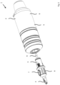
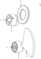
- Fig. 1 and 2 show schematic perspective views of a hand-held device 1 with a drive module 2 providing a drive device and a needle module 3 coupled thereto and providing a skin piercing device, which according to Fig. 2 can be detached from the hand module 2, in particular after use of the hand device 1 for local puncturing of a skin, in order to dispose of the needle module 3, which can be designed as a disposable module.
- the linear drive movement is transmitted to the piercing device, so that the one or more piercing needles can be moved back and forth.
- the coupling component 6 can be part of the coupling device or formed separately therefrom in order to pick up the linear movement and transmit it to the piercing device.
- the handheld device 1 can be designed as a tattooing device or as a device for applying permanent makeup.
- a dye can be introduced into the skin through an opening 7 on a module housing 8.
- the handheld device 1 can also be used for localized piercing of the skin without introducing any substance.
- the rotor component 21 rotates about a motor or rotor axis, which is formed in the axial direction of a motor shaft 24.
- a protruding part 25 of the motor shaft 24 can be omitted.
- the tapping component 27 is coupled to a connecting rod component 29 (cf. Fig. 5 and 6 ).
- the connecting rod component 29 is formed at its end with a connecting rod eye 30, which, in the example shown, essentially completely surrounds a shaft shoulder 30 on the crank pin 28.
- the connecting rod component 29 is connected to the tapping component 27 in a rotationally decoupled manner.
- a ball bearing 32 is provided in a surrounding outer ring 33, which is arranged on the eccentrically arranged crank pin 28 above the connecting rod component 29.
Landscapes
- Health & Medical Sciences (AREA)
- Life Sciences & Earth Sciences (AREA)
- Engineering & Computer Science (AREA)
- Environmental Sciences (AREA)
- Animal Behavior & Ethology (AREA)
- Veterinary Medicine (AREA)
- Biomedical Technology (AREA)
- Heart & Thoracic Surgery (AREA)
- Hematology (AREA)
- Medical Informatics (AREA)
- Dermatology (AREA)
- General Health & Medical Sciences (AREA)
- Public Health (AREA)
- Anesthesiology (AREA)
- Virology (AREA)
- Zoology (AREA)
- Animal Husbandry (AREA)
- Biodiversity & Conservation Biology (AREA)
- Birds (AREA)
- Power Engineering (AREA)
- Percussion Or Vibration Massage (AREA)
- Manipulator (AREA)
Description
- Die Erfindung betrifft eine Antriebseinrichtung für ein Handgerät zum lokalen Aufstechen einer Haut sowie ein Handgerät zum lokalen Aufstechen einer Haut.
- Solche Handgeräte dienen dazu, eine menschliche oder eine tierische Haut lokal aufzustechen, insbesondere in Verbindung mit dem Tätowieren oder zum Ausbilden von permanentem Makeup. Hierbei wird beim und / oder nach dem lokalen Aufstechen der Haut ein Farbstoff in die Haut eingebracht. Das lokale Aufstechen der Haut mit einem solchen Handgerät kann aber auch zum Einbringen kosmetischer oder medizinischer Wirkstoffe verwendet werden. Alternativ ist die Verwendung derartiger Handgeräte zum lokalen Aufstechen der Haut ohne Substanz- oder Wirkstoffeintrag bekannt, zum Beispiel zur Hautstimulierung.
- Bei Handgeräten zum lokalen Aufstechen der Haut ist üblicherweise eine Antriebseinrichtung mit einem elektrischen Motor vorgesehen, mit dem eine drehende Antriebsbewegung bereitgestellt wird. Die Antriebsbewegung wird mit Hilfe einer Kopplungseinrichtung abgegriffen und in eine Linearbewegung umgewandelt, die auf eine Stecheinrichtung eingekoppelt wird, um eine oder mehrere Stechnadeln im Betrieb mit einer Wiederholfrequenz vor und zurück zu bewegen, um die Haut lokal aufzustechen.
- Das Dokument
CN 108 635 665 A offenbart ein geräuscharmes Tattoo-Auffrischungsinstrument, das ein Bedienfeld vom Uhrentyp, einen Bedienstift, einen starken magnetischen Verbinder und eine Augenbrauen-Tätowierungsnadel umfasst, wobei das Bedienfeld vom Uhrentyp mit dem Bedienstift verbunden ist, der Bedienstift mit einem Hohlschalenmotor installiert ist, der Hohlschalenmotor mit der Augenbrauen-Tätowierungsnadel an der Vorderseite des Bedienstifts verbunden ist und das Bedienfeld vom Uhrentyp mit einem Einschaltknopf und einem Leistungseinstellknopf installiert ist. - Dokument
US 2005 / 0 010 236 A1 betrifft eine Vorrichtung zum Aufbringen einer Tätowierung oder von permanentem Make-up, mit einem Einwegmodul, welches lösbar an einem Handstück angeordnet ist, einer Nadel, die mit einem Ende in einem Nadelschaft gehalten wird, die bewegbar in einer an dem Einwegmodul gebildeten Nadelführung gelagert ist und die mit einem anderen Ende durch eine Nadeldüsenöffnung zum Ausbringen eines Farbstoffs verläuft, und einem an den Nadelschaft zum Vor- und Zurückbewegen der Nadel gekoppelten und von mehreren Bauteilen gebildeten Antriebsmechanismus, wobei die mehreren Bauteile des Antriebsmechanismus einen Antrieb und Kopplungsmittel zum Koppeln des Antriebs an den Nadelschaft umfassen. Zumindest ein Teil der mehreren Bauteile des Antriebsmechanismus ist in dem Einwegmodul angeordnet und zusammen mit dem Einwegmodul von dem Handstück abnehmbar ist. - Das Dokument
US 2020 / 0 324 098 A1 betrifft ein Antriebssystem für ein Handgerät zum lokalen Aufstechen einer menschlichen oder einer tierischen Haut, mit einer Antriebseinrichtung, die eingerichtet ist, eine drehende Antriebsbewegung bereitzustellen; und einem Wandlungsmechanismus, weicher zum Abgreifen der drehenden Antriebsbewegung an die Antriebseinrichtung koppelt und eingerichtet ist, ausgehend von der drehenden Antriebsbewegung eine lineare Vorwärts- und Rückwärtsbewegung bereitzustellen, der Wandlungsmechanismus aufweisend: eine Taumelscheibenanordnung, die an einer Lagereinrichtung angeordnet ist und über ein Drehgelenk an ein distales Gelenkbauteil koppelt, welches von der Lagereinrichtung aufgenommen ist; eine an der Taumelscheibenanordnung gebildete Taumelscheibe, welche im Betrieb aufgrund der drehenden Antriebsbewegung eine Taumelbewegung ausführt; einen Abgriff, weicher an die Taumelscheibe koppelt und eingerichtet ist, mittels Zusammenwirken mit der Taumelscheibe die lineare Vorwärts- und Rückwärtsbewegung zum Abgreifen bereitzustellen; und ein Einstellbauteil, welches an die Taumelscheibenanordnung koppelt und verlagerbar angeordnet ist, derart, dass zum Einstellen eines Hubs der an dem Abgriff bereitgestellten linearen Vorwärts- und Rückwärtsbewegung eine Neigung der Taumelscheibe zur Längsrichtung mittels Verlagern des Einstellbauteils veränderbar ist. - Aufgabe der Erfindung ist es, eine Antriebseinrichtung für ein Handgerät zum lokalen Aufstechen einer Haut sowie ein solches Handgerät zu schaffen, mit denen eine Antriebsbewegung für eine Stecheinrichtung effizient und für unterschiedliche Anwendungen flexibel bereitgestellt werden kann.
- Zur Lösung sind eine Antriebseinrichtung für ein Handgerät zum lokalen Aufstechen einer Haut sowie ein Handgerät zum lokalen Aufstechen einer Haut nach den unabhängigen Ansprüchen 1 und 12 geschaffen. Ausgestaltungen sind Gegenstand von abhängigen Unteransprüchen. Nach einem Aspekt ist eine Antriebseinrichtung für ein Handgerät zum lokalen Aufstechen einer Haut geschaffen, die Folgendes aufweist: ein Gehäuse, welches mit einem Modulgehäuse einer Hautstecheinrichtung verbindbar ist; und eine elektrische Antriebsvorrichtung, die in dem Gehäuse angeordnet ist und ein Abgriffbauteil aufweist, welches eingerichtet ist, einen Abgriff zum Abgreifen einer mittels der elektrischen Antriebsvorrichtung erzeugten drehenden Antriebsbewegung für die Hautstecheinrichtung bereitzustellen. Die elektrische Antriebsvorrichtung weist einen als Außenläufer mit einem rotierenden Rotorbauteil ausgebildeten elektrischen Motor auf, bei dem das Abgriffbauteil an dem Rotorbauteil und in Bezug auf eine Rotorachse exzentrisch angeordnet ist.
- Nach einem weiteren Aspekt ist ein Handgerät zum lokalen Aufstechen einer Haut mit einer Antriebseinrichtung sowie einer Hautstecheinrichtung mit einem Modulgehäuse geschaffen, welche mit der Antriebseinrichtung lösbar verbunden ist und bei der im Betrieb eine Stecheinrichtung in einer vorderseitigen Modulgehäuseöffnung vor und zurückbewegt werden kann. Das Handgerät umfasst eine Kopplungseinrichtung, die als Teil der Antriebseinrichtung und / oder der Hautstecheinrichtung gebildet und eingerichtet ist, eine in der Antriebseinrichtung bereitgestellte drehende Antriebsbewegung am Abgriff eines als Außenläufer ausgebildeten elektrischen Motors abzugreifen und in eine Linearbewegung für die Stecheinrichtung auf diese zu koppeln.
- Es ist vorgesehen, den Abgriff am elektrischen Motor getrennt von der Motorwelle an dem Rotorbauteil des elektrischen Motors auszubilden. Es ist so vermieden, zum Ausbilden einer Exzentrizität des Abgriffs in Bezug auf die Rotor- oder Motorachse des elektrischen Motors zusätzliche Bauteile auf der Motorwelle zu montieren, an denen dann der Abgriff gebildet ist. Auf diese Weise kann die Antriebseinrichtung mit verbesserter mechanischer Stabilität ausgebildet werden.
- Mittels Anordnen des Abgriffs auf dem Rotorbauteil des Außenläufers entfällt die sonst beim Stand der Technik notwendige Umhüllung einer Motorwelle durch ein üblicherweise zylindrisches, exzentrisch angeordnetes Abgriffbauteil auf der Motorwelle. Das am Rotorbauteil (nicht auf der Motorwelle) angeordnete Abgriffbauteil kann so hinsichtlich seiner Abmessungen kleiner gewählt werden, bis wahlweise hin zu einer Größe kleiner als die Motorwelle, zum Beispiel betreffend einen Durchmesser. Der am Rotorbauteil selbst vorgesehene Abgriff wird allein durch ein Biegemoment beansprucht und kann daher kleiner gehalten werden.
- Mit der Kopplungseinrichtung ist ein Wandlungsmechanismus bereitgestellt oder implementiert, mit dem die drehende Antriebsbewegung in die Linearbewegung gewandelt wird, wie dies als solches für Handgeräte zum lokalen Aufstechen einer Haut in verschiedenen Ausgestaltungen bekannt ist. Die Einkopplung der Antriebsbewegung auf die Stecheinrichtung kann derart ausgeführt sein, dass die Stecheinrichtung hierdurch zwangsweise vor- und / oder zurückbewegt wird. Alternativ oder ergänzend können andere oder weitere Kräfte auf die Stecheinrichtung eingekoppelt werden, die deren Bewegung beim Vor- und / oder Zurückbewegen bewirken oder unterstützen, beispielsweise eine Federkraft uns / oder eine von einer gestreckten Membran aufgebrachte Kraft, wie dies als solches ebenso in verschiedenen Ausführungen bekannt ist.
- Mit dem Ausbilden des Abgriffbauteils an dem Rotorbauteil selbst kann ein exzentrischer Kurbelzapfen bereitgestellt sein, an dem die drehende Antriebsbewegung abgegriffen werden kann. In einer Ausführungsform kann das Rotorbauteil, an dem das Abgriffbauteil angeordnet ist, eine rotierende Außenglocke oder eine rotierendes Gehäusebauteil des elektrischen Motors sein.
- Es kann vorgesehen sein, den elektrischen Motor frei von einem Motorwellenkoppelzapfen auszubilden, da der Abgriff der drehenden Antriebsbewegung über das Abgriffbauteil an dem Rotorbauteil erfolgt. Der elektrische Motor kann so frei von einer äußeren Motorwelle sein.
- Das Abgriffbauteil kann auf einer Stirnfläche des Rotorbauteils angeordnet sein. Alternativ kann das Abgriffbauteil im Bereich einer Umfangsfläche des Rotorbauteils oder im Bereich eines Übergangs zwischen der Stirnfläche und der Umfangsfläche angeordnet sein.
- Das Abgriffbauteil kann an dem Rotorbauteil verlagerbar angeordnet sein, derart, dass eine Exzentrizität des Abgriffs in Bezug auf die Rotorachse einstellbar ist. Die Verlagerbarkeit des Abgriffbauteils an dem Rotorbauteil ist insbesondere in radialer Richtung gegeben, so dass ein Abstand zwischen dem den Abgriff bereitstellenden Abgriffbauteil und der Rotor- oder Motorachse vergrößert und verkleinert werden kann. Hierzu kann das Abgriffbauteil beispielsweise mittels einer lösbaren Klemm- oder Schraubverbindung an dem Rotorbauteil montiert sein, die gelöst werden kann, um das Abgriffbauteil an dem Rotorbauteil zu verlagern. Nach der Verlagerung kann die Verbindung wieder festgestellt werden, um das Abgriffbauteil an dem Rotorbauteil in der neuen Stellung zu fixieren. Mit Hilfe einer Änderung der Exzentrizität kann beim Koppeln der Antriebseinrichtung an die Hautstecheinrichtung ein Hub für die Stecheinrichtung (Länge der Vor- und Zurückbewegung; maximaler Abstand zwischen Umkehrpunkten einer linearen Stechbewegung) eingestellt werden, insbesondere eines Nadelhubs einer Nadeleinrichtung der Hautstecheinrichtung, die eine oder mehrere Stechnadeln aufweist, welche zum lokalen Aufstechen der Haut vor und zurück bewegt werden.
- Das Abgriffbauteil kann an dem Rotorbauteil einstückig angeformt sein. Zum einstückigen Anformen des Abgriffbauteils an dem Rotorbauteil kann vorgesehen sein, zwischen den Bauteilen zum Beispiel eine Kleb- oder eine Schweißverbindung auszubilden.
- Das Abgriffbauteil kann an dem Rotorbauteil lösbar angeordnet sein. Eine lösbare Verbindung zwischen Abgriffbauteil und Rotorbauteil kann beispielsweise mittels einer Schraub- oder eine Steckverbindung ausgebildet sein.
- Dem Abgriffbauteil kann eine Ausgleichsmasse zugeordnet sein. Mit Hilfe der dem Abgriffbauteil zugeordneten Ausgleichsmasse werden Vibrationen im Betrieb der Antriebseinrichtung vermindert oder ganz beseitigt.
- Die Ausgleichsmasse kann mit einem Ausgleichsbauteil gebildet sein, welches an dem Rotorbauteil montiert oder angeordnet ist. Das Ausgleichsbauteil kann verlagerbar an dem Rotorbauteil angeordnet sein. Auf diese Weise ist eine Einstellbarkeit der Ausgleich- oder Auswuchtwirkung ermöglicht, beispielsweise dann, wenn die Exzentrizität für den Abgriff an dem Rotorbauteil verändert wird.
- Das Ausgleichsbauteil kann an dem Abgriffbauteil angeordnet sein. Bei dieser Ausführungsform ist das Ausgleichsbauteil an dem Abgriffbauteil montiert. Beispielsweise kann ein Vorsprung oder ein Zapfen des Abgriffbauteils eine Öffnung an dem Ausgleichsbauteil durchgreifen, wenn dieses an dem Abgriffbauteil montiert ist. Hierbei kann vorgesehen sein, dass das Ausgleichsbauteil in mehreren Drehstellungen um das Abgriffbauteil herum jeweils fixierbar ist, zum Beispiel mittels einer lösbaren Feststellschraube, um die Ausgleichswirkung veränderbar bereitzustellen.
- An dem Abgriffbauteil kann ein Lagerungsbauteil angeordnet sein, welches eingerichtet ist, zum Abgreifen der drehenden Antriebsbewegung an ein Pleuelbauteil zu koppeln. Die Lagerung des Pleuelbauteils an dem Abgriffbauteil kann beispielsweise unter Verwendung eines Kugel- oder eines Gleitlagers ausgeführt sein.
- Das Abgriffbauteil kann an einem Rotorgehäusebauteil angeordnet sein. Zum Beispiel kann das Rotorgehäusebauteil eine rotierende Außenglocke des elektrischen Motors sein. Das Rotorgehäusebauteil kann eine Topf-, Ring- oder eine Scheibenform aufweisen.
- Mit dem Gehäuse der Antriebseinrichtung kann ein Handstück gebildet sein, welches von einem Nutzer gegriffen werden kann.
- Bei dem Handgerät zum lokalen Aufstechen einer Haut kann die Hautstecheinrichtung mit einem als Einwegmodul ausgeführten Stechmodul gebildet sein. Als Stechmodul ausgeführte Einwegmodule sind als solche in verschiedenen Ausführungsformen bekannt. Sie ermöglichen es, die Hautstecheinrichtung nach einer Benutzung auszutauschen, um so ein Handgerät mit einem hohen Hygienestandard bereitzustellen.
- Die Kopplungseinrichtung kann bei dem Handgerät zum lokalen Aufstechen ein Pleuelbauteil aufweisen, welches mit einem den Abgriff bereitstellenden Abgriffbauteil des elektrischen Motors drehentkoppelnd verbunden ist. Das Pleuelbauteil kann mit einer Pleuelstange ausgeführt sein, die antriebseitig ein Pleuelauge aufweist, das in einer gekoppelten Stellung das Abgriffbauteil teilweise oder im Wesentlichen vollständig umgreift. Eine Drehentkopplung kann mittels eines Kugel- oder eines Gleitlagers ausgeführt sein. Ist an dem Abgriffbauteil ein Ausgleichsbauteil zum Bereitstellen einer dem Abgriffbauteil zugeordneten Ausgleichsmasse angeordnet, kann das Ausgleichsbauteil in Bezug auf das Rotorbauteil in einer proximalen Stellung angeordnet sein, wohingegen eine Lagerung des Pleuelbauteils an dem Abgriffbauteil in einer distalen Stellung ausgebildet ist.
- Die vorangehend im Zusammenhang mit der Antriebseinrichtung erläuterten weiteren Ausgestaltungen können in Verbindung mit dem Handgerät zum lokalen Aufstechen der Haut entsprechend vorgesehen sein.
- Im Folgenden werden weitere Ausführungsbeispiele unter Bezugnahme auf Figuren einer Zeichnung erläutert. Hierbei zeigen:
- Fig. 1
- eine schematische perspektivische Darstellung eines Handgeräts zum lokalen Aufstechen einer Haut mit einer Antriebseinrichtung und einer hiermit verbundenen Hautstecheinrichtung, die mit einem Antriebsmodul und einem Nadelmodul gebildet sind;
- Fig. 2
- eine schematische perspektivische Darstellung des Handgeräts aus
Fig. 1 , wobei die mit dem Nadelmodul gebildete Hautstecheinrichtung von der Antriebseinrichtung getrennt ist; - Fig. 3
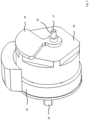
- eine perspektivische Darstellung eines als Außenläufer ausgebildeten elektrischen Motors von schräg vorn;
- Fig. 4
- eine schematische perspektivische Darstellung des elektrischen Motors aus
Fig. 3 von schräg hinten; - Fig. 5
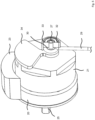
- eine schematische perspektivische Darstellung des elektrischen Motors aus
Fig. 4 von schräg hinten und teilweise im Schnitt, wobei ein Pleuelbauteil an einen exzentrischen Abgriff koppelt; - Fig. 6
- eine schematische perspektivische Darstellung des elektrischen Motors aus
Fig. 5 von schräg hinten in einer anderen Drehstellung; - Fig. 7
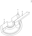
- eine schematische perspektivische Darstellung eines Endabschnitts des Pleuelbauteils im Detail;
- Fig. 8
- eine schematische perspektivische Darstellung des Endabschnitts des Pleuelbauteils aus
Fig. 7 im Detail und im Schnitt; - Fig. 9
- eine schematische perspektivische Darstellung eines Ausgleichsbauteils in einstückiger und mehrstückiger Ausführung.
-
Fig. 1 und2 zeigen schematische perspektivische Darstellungen eines Handgeräts 1 mit einem eine Antriebseinrichtung bereitstellenden Antriebsmodul 2 und einem hieran gekoppelten und eine Hautstecheinrichtung bereitstellenden Nadelmodul 3, welches gemäßFig. 2 von dem Handmodul 2 gelöst werden kann, insbesondere nach einer Nutzung des Handgeräts 1 zum lokalen Aufstechen einer Haut, um das als Einwegmodul ausführbare Nadelmodul 3 zu entsorgen. - Das Handgerät 1 ist eingerichtet, eine menschliche oder eine tierische Haut im Betrieb lokal mehrfach mit einer Wiederholfrequenz aufzustechen. Hierzu wird eine Stecheinrichtung mit einer oder mehreren Stechnadeln (nicht dargestellt) durch eine vorderseitige Gehäuseöffnung 4 an dem Nadelmodul 3 vor und zurück bewegt, wie dieses als solches bekannt ist. Um die lineare Vor- und Zurückbewegung der Stecheinrichtung bereitzustellen, ist eine Kopplungseinrichtung (nicht dargestellt) vorgesehen, die beim gezeigten Beispiel in einem Gehäuse 5 des Antriebsmoduls 2 angeordnet und eingerichtet ist, eine von einem elektrischen Motor der Antriebseinrichtung bereitgestellte drehende Antriebsbewegung abzugreifen und in eine Linearbewegung zum Vor- und Zurückbewegen der Stecheinrichtung zu wandeln und die auf die eine oder mehreren Stechnadeln direkt oder indirekt zu koppeln. Somit ist mit der Kopplungseinrichtung ein Wandlungsmechanismus bereitgestellt, wie dies für derartige Handgeräte an sich bekannt ist. Die Stecheinrichtung wird dann mit einer Wiederholfrequenz vor und zurück bewegt.
- Über ein mit der einen oder den mehreren Stechnadeln der Stecheinrichtung verbundenes Kopplungsbauteil 6 (vgl.
Fig. 2 ) der mit dem Nadelmodul 3 gebildeten Hautstecheinrichtung wird die lineare Antriebsbewegung auf die Stecheinrichtung übertragen, so dass die eine oder die mehreren Stechnadeln vor und zurückbewegt werden können. Das Kopplungsbauteil 6 kann Teil der Kopplungseinrichtung sein oder getrennt hiervon gebildet sein, um die Linearbewegung abzugreifen und auf die Stecheinrichtung zu geben. - Das Handgerät 1 kann als Tätowiergerät oder als Gerät zum Ausbilden von permanentem Makeup ausgebildet sein. Hierbei kann über eine Öffnung 7 an einem Modulgehäuse 8 ein Farbstoff zugeführt werden, der in die Haut einzubringen ist. Das Handgerät 1 kann aber auch zum lokalen Aufstechen einer Haut ohne Substanzeintrag verwendet werden.
- Mit dem Gehäuse 5 der mittels Antriebsmodul 2 bereitgestellten Antriebseinrichtung ist ein Handstück 9 gebildet, welches vom Nutzer gegriffen werden kann, um das Handgerät 1 im Betrieb zu führen.
- Unter Bezugnahme auf die
Fig. 3 bis 9 werden nachfolgend Ausführungsformen für einen als Außenläufer ausgebildeten elektrischen Motor 20 erläutert, der im Gehäuse 5 der mittels Antriebsmodul 2 bereitgestellten Antriebseinrichtung aufgenommen ist, um die drehende Antriebsbewegung bereitzustellen. Beim Außenläufer dreht sich ein außenliegendes Rotorbauteil 21 im Betrieb. Bei der gezeigten Ausführungsform bildet das Rotorbauteil 21 eine rotierende Außenglocke oder ein rotierendes Außengehäuse des elektrischen Motors 20, welches eine Topfform aufweisen kann. Der elektrische Motor 20 kann mit Hilfe eines Andockflansches 22 montiert werden. Elektrische Anschlüsse / Abgriffe sind in einem Block 23 angeordnet. - Das Rotorbauteil 21 dreht sich um eine Motor- oder Rotorachse, welches in Axialrichtung einer Motorwelle 24 ausgebildet ist. Ein abstehender Teil 25 der Motorwelle 24 kann entfallen.
- Für den Betrieb des Handgeräts 1 ist vorgesehen, eine exzentrische Drehbewegung mit Hilfe des elektrischen Motors 20 bereitzustellen, die eine Antriebsbewegung für das Vor- und Zurückbewegen der Stechvorrichtung bildet. Hierzu ist gemäß
Fig. 4 ein auf einer (rückseitigen) Stirnfläche 26 des Rotorbauteils 21 in Bezug auf die Motorwelle 24 exzentrisch angeordnetes Abgriffbauteil 27 vorgesehen, welches im Ausführungsbeispiel mit einem exzentrischen Kurbelzapfen 28 gebildet ist. Das Abgriffbauteil 27 kann an dem Rotorbauteil 21 beispielsweise angeschweißt oder angeklebt sein. Eine lösbare Montage an dem Rotorbauteil 21 kann vorgesehen sein, insbesondere derart, dass das Abgriffbauteil 27 in mehreren Stellung in unterschiedlichem Abstand zur Motorwelle 24 fixiert werden kann, um so die Exzentrizität einzustellen. - Zum exzentrischen Abgreifen der drehenden Antriebsbewegung koppelt das Abgriffbauteil 27 an ein Pleuelbauteil 29 (vgl.
Fig. 5 und6 ). Das Pleuelbauteil 29 ist endseitig mit einem Pleuelauge 30 gebildet, welches einen Wellenabsatz 30 auf dem Kurbelzapfen 28 im gezeigten Beispiel im Wesentlichen vollständig umgreift. Das Pleuelbauteil 29 ist mit dem Abgriffbauteil 27 drehentkoppelt verbunden. Hierzu ist ein Kugellager 32 in einem umgebenden Außenring 33 vorgesehen, welches am exzentrisch angeordneten Kurbelzapfen 28 oberhalb des Pleuelbauteils 29 angeordnet ist. - Insbesondere gemäß den
Fig. 4 bis 6 ist an dem Abgriffbauteil 27 weiterhin ein Ausgleichsbauteil 34 vorgesehen, welches eine dem Abgriffbauteil 27 zugeordnete Ausgleichsmasse für eine Auswuchtung bereitstellt. Für das Ausgleichsbauteil 34 zeigen dieFig. 7 bis 9 die einstückige sowie eine alternative mehrstückige Ausbildung. Bei der mehrstückigen Ausführung kann ein Normbauteil 35 auf dem Rotorbauteil 21 außenseitig angeklebt oder angeschweißt sein. - Es kann vorgesehen sein, dass das Ausgleichsbauteil auf dem Rotorbauteil 21 verlagerbar angeordnet ist, derart, dass ein Abstand zwischen einer Rotorachse des elektrischen Motors 20 und dem Abgriffbauteil in radialer Richtung veränderbar ist, so dass die Exzentrizität des Abgriffbauteils einstellbar ist. Im Zusammenwirken mit dem Pleuelbauteil kann so ein Hub für die Vor- und Zurückbewegung der Stecheinrichtung eingestellt werden.
- Die in der vorstehenden Beschreibung, den Ansprüchen sowie der Zeichnung offenbarten Merkmale können sowohl einzeln als auch in beliebiger Kombination für die Verwirklichung der verschiedenen Ausführungen von Bedeutung sein.
Claims (15)
- Antriebseinrichtung für ein Handgerät (1) zum lokalen Aufstechen einer Haut, mit:- einem Gehäuse (5), welches mit einem Modulgehäuse (8) einer Hautstecheinrichtung verbindbar ist; und- einer elektrischen Antriebsvorrichtung, die in dem Gehäuse (5) angeordnet ist und ein Abgriffbauteil (27) aufweist, welches eingerichtet ist, einen Abgriff zum Abgreifen einer mittels der elektrischen Antriebsvorrichtung erzeugten drehenden Antriebsbewegung für die Hautstecheinrichtung bereitzustellen;dadurch gekennzeichnet, dass die elektrische Antriebsvorrichtung einen als Außenläufer mit einem rotierenden Rotorbauteil (21) ausgebildeten elektrischen Motor (20) aufweist, bei dem das Abgriffbauteil (27) an dem Rotorbauteil (21) und in Bezug auf eine Rotorachse exzentrisch angeordnet ist.
- Antriebseinrichtung nach Anspruch 1, dadurch gekennzeichnet, dass das Abgriffbauteil (27) auf einer Stirnfläche (26) des Rotorbauteils (21) angeordnet ist.
- Antriebseinrichtung nach Anspruch 1 oder 2, dadurch gekennzeichnet, dass das Abgriffbauteil (27) an dem Rotorbauteil (21) verlagerbar angeordnet ist, derart, dass eine Exzentrizität des Abgriffs in Bezug auf die Rotorachse einstellbar ist.
- Antriebseinrichtung nach mindestens einem der vorangehenden Ansprüche, dadurch gekennzeichnet, dass das Abgriffbauteil (27) an dem Rotorbauteil (21) einstückig angeformt ist.
- Antriebseinrichtung nach mindestens einem der Ansprüche 1 bis 3, dadurch ge- kennzeichnet, dass das Abgriffbauteil (27) an dem Rotorbauteil (21) lösbar angeordnet ist.
- Antriebseinrichtung nach mindestens einem der vorangehenden Ansprüche, gekennzeichnet durch eine dem Abgriffbauteil (27) zugeordnete Ausgleichsmasse.
- Antriebseinrichtung nach Anspruch 6, dadurch gekennzeichnet, dass die Ausgleichsmasse mit einem Ausgleichsbauteil (34) gebildet ist, welches an dem Rotorbauteil (21) montiert ist.
- Antriebseinrichtung nach Anspruch 7, dadurch gekennzeichnet, dass das Ausgleichsbauteil (34) an dem Abgriffbauteil (27) angeordnet ist.
- Antriebseinrichtung nach mindestens einem der vorangehenden Ansprüche, dadurch gekennzeichnet, dass an dem Abgriffbauteil (27) ein Lagerungsbauteil angeordnet ist, welches eingerichtet ist, zum Abgreifen der drehenden Antriebsbewegung an ein Pleuelbauteil (29) zu koppeln.
- Antriebseinrichtung nach mindestens einem der vorangehenden Ansprüche, dadurch gekennzeichnet, dass das Abgriffbauteil (27) an einem Rotorgehäusebauteil angeordnet ist.
- Antriebseinrichtung nach mindestens einem der vorangehenden Ansprüche, dadurch gekennzeichnet, dass mit dem Gehäuse (5) ein Handstück (9) gebildet ist.
- Handgerät (1) zum lokalen Aufstechen einer Haut, mit:- einer Antriebseinrichtung nach mindestens einem der vorangehenden Ansprüche;- einer Hautstecheinrichtung mit einem Modulgehäuse (8), welche mit der Antriebseinrichtung lösbar verbunden ist und bei der im Betrieb eine Stecheinrichtung in einer vorderseitigen Modulgehäuseöffnung (5) vor und zurück bewegt werden kann; und- einer Kopplungseinrichtung, die mit der Antriebseinrichtung und / oder der Hautstecheinrichtung gebildet und eingerichtet ist, eine in der Antriebseinrichtung bereitgestellte drehende Antriebsbewegung am Abgriff eines als Außenläufer ausgebildeten elektrischen Motors (20) abzugreifen und in eine Linearbewegung zu wandeln und diese auf die Stecheinrichtung zu koppeln.
- Handgerät nach Anspruch 12, dadurch gekennzeichnet, dass die Hautstecheinrichtung mit einem als Einwegmodul ausgeführten Nadelmodul (3) gebildet ist.
- Handgerät nach Anspruch 12 oder 13, dadurch gekennzeichnet, dass die Kopplungseinrichtung ein Pleuelbauteil (29) aufweist, welches mit einem den Abgriff bereitstellenden Abgriffbauteil (27) des elektrischen Motors (20) drehentkoppelnd verbunden ist.
- Handgerät nach mindestens einem der Ansprüche 12 bis 14, dadurch gekenn- zeichnet, dass mit einem Gehäuse (5) der Antriebseinrichtung ein vom Nutzer greifbares Handstück (9) gebildet ist.
Priority Applications (2)
| Application Number | Priority Date | Filing Date | Title |
|---|---|---|---|
| EP21172237.6A EP4085963B1 (de) | 2021-05-05 | 2021-05-05 | Antriebseinrichtung für ein handgerät zum lokalen aufstechen einer haut und handgerät |
| US17/737,167 US20220355090A1 (en) | 2021-05-05 | 2022-05-05 | Drive device for a hand-held device for locally puncturing a skin, and hand-held device |
Applications Claiming Priority (1)
| Application Number | Priority Date | Filing Date | Title |
|---|---|---|---|
| EP21172237.6A EP4085963B1 (de) | 2021-05-05 | 2021-05-05 | Antriebseinrichtung für ein handgerät zum lokalen aufstechen einer haut und handgerät |
Publications (3)
| Publication Number | Publication Date |
|---|---|
| EP4085963A1 EP4085963A1 (de) | 2022-11-09 |
| EP4085963C0 EP4085963C0 (de) | 2025-03-12 |
| EP4085963B1 true EP4085963B1 (de) | 2025-03-12 |
Family
ID=75825509
Family Applications (1)
| Application Number | Title | Priority Date | Filing Date |
|---|---|---|---|
| EP21172237.6A Active EP4085963B1 (de) | 2021-05-05 | 2021-05-05 | Antriebseinrichtung für ein handgerät zum lokalen aufstechen einer haut und handgerät |
Country Status (2)
| Country | Link |
|---|---|
| US (1) | US20220355090A1 (de) |
| EP (1) | EP4085963B1 (de) |
Families Citing this family (1)
| Publication number | Priority date | Publication date | Assignee | Title |
|---|---|---|---|---|
| CN118120649B (zh) * | 2024-04-07 | 2025-10-10 | 金皇 | 一种动物可穿戴装置及其穿戴方法 |
Family Cites Families (10)
| Publication number | Priority date | Publication date | Assignee | Title |
|---|---|---|---|---|
| US5472449A (en) * | 1993-07-26 | 1995-12-05 | Chou; Kuei C. | Permanent pigment applicator having a detachable needle coupler |
| ATE313351T1 (de) * | 2003-07-08 | 2006-01-15 | Medium Tech Medizingeraete Gmb | Vorrichtung zum aufbringen einer tätowierung oder von permanentem make-up |
| US8733211B2 (en) * | 2011-02-16 | 2014-05-27 | Michael Snijders | Tattoo machines, methods of making tattoo machines, and methods of using tattoo machines |
| US20190217072A1 (en) * | 2018-01-18 | 2019-07-18 | Long Xiao | Devices for applying liquid to skin |
| US20150367118A1 (en) * | 2014-06-12 | 2015-12-24 | Mt.Derm Gmbh | Handheld device for repeated piercing of a human or animal skin and drive module |
| US9662483B2 (en) * | 2014-09-16 | 2017-05-30 | Gaston Siciliano | Rotary tattoo machine |
| CN108635665A (zh) * | 2018-07-30 | 2018-10-12 | 付广义 | 一种高静音的腕表式纹绣纹身用润色仪 |
| EP3725358B1 (de) * | 2019-04-15 | 2023-09-13 | MT.DERM GmbH | Antriebssystem und antriebsmodul für ein handgerät zum lokalen aufstechen einer menschlichen oder einer tierischen haut sowie handgerät |
| US11383071B2 (en) * | 2020-03-10 | 2022-07-12 | Long Xiao | Tattoo device with motor having built-in motion conversion member |
| EP4005626A1 (de) * | 2020-11-26 | 2022-06-01 | Xiangyu Chen | Drahtlose tätowiermaschine für fingersteuerungsbetrieb |
-
2021
- 2021-05-05 EP EP21172237.6A patent/EP4085963B1/de active Active
-
2022
- 2022-05-05 US US17/737,167 patent/US20220355090A1/en not_active Abandoned
Also Published As
| Publication number | Publication date |
|---|---|
| EP4085963C0 (de) | 2025-03-12 |
| US20220355090A1 (en) | 2022-11-10 |
| EP4085963A1 (de) | 2022-11-09 |
Similar Documents
| Publication | Publication Date | Title |
|---|---|---|
| EP1958659B1 (de) | Antriebsmodul für eine Vorrichtung zum lokalen Aufstechen einer menschlichen oder einer tierischen Haut und Handgerät | |
| EP1884191B1 (de) | Blutentnahmesystem | |
| EP2594312B1 (de) | Vorrichtung zum Aufstechen eines organischen Gewebes und Antriebsmodul | |
| EP2954927A1 (de) | Antriebsmodul für ein handgerät zum wiederholten aufstechen einer menschlichen oder tierischen haut, handgerät und verfahren | |
| EP2682146B1 (de) | Handgerät zum Tätowieren oder Applizieren von permanentem Make-up und Nadelmodul mit einstellbarer Einstechtiefe | |
| EP4241824B1 (de) | Handgerät zum lokalen aufstechen einer haut | |
| DE3390003C2 (de) | ||
| EP1495782B1 (de) | Vorrichtung zum Aufbringen einer Tätowierung oder von permanentem Make-up | |
| EP2954926A1 (de) | Handgerät zum wiederholten aufstechen einer menschlichen oder einer tierischen haut | |
| DE69432557T2 (de) | Kathetersystem für bilderzeugung in vorwärtsrichtung | |
| EP2462979B1 (de) | Vorrichtung zum wiederholten Aufstechen von Haut und Stechmodul | |
| EP2601986B1 (de) | Adapter für Bohrantrieb und Lavage-System | |
| EP2438867B1 (de) | Medizinisches Instrument | |
| EP2213229A1 (de) | Blutentnahmesystem | |
| DE10203372A1 (de) | Medizinisches Untersuchungs- und/oder Behandlungssystem | |
| DE102004051793A1 (de) | Chirurgisches Instrument mit winkligem Aufsatz | |
| DE102013225117A1 (de) | Antriebsanordnung für ein endoskopisches Schaftinstrument | |
| EP2422731A1 (de) | Aktuator zur Skoliosekorrektur | |
| EP4376758B1 (de) | Chirurgisches instrument und lenkgetriebe dafür | |
| EP3363492B1 (de) | Nadelmodul für eine antriebsgesteuerte vorrichtung zum wiederholten aufstechen einer menschlichen oder einer tierischen haut und handgerät | |
| EP4074363A1 (de) | Microneedling-handgerät zum lokalen aufstechen einer haut, hautstecheinrichtung und artikel | |
| EP2174591A1 (de) | Stechgerät | |
| EP3725358B1 (de) | Antriebssystem und antriebsmodul für ein handgerät zum lokalen aufstechen einer menschlichen oder einer tierischen haut sowie handgerät | |
| EP2954925A1 (de) | Handgerät zum wiederholten Aufstechen einer menschlichen oder tierischen Haut und Antriebsmodul | |
| EP2311373B1 (de) | Stechsystem zur Entnahme einer Körperflüssigkeit |
Legal Events
| Date | Code | Title | Description |
|---|---|---|---|
| PUAI | Public reference made under article 153(3) epc to a published international application that has entered the european phase |
Free format text: ORIGINAL CODE: 0009012 |
|
| STAA | Information on the status of an ep patent application or granted ep patent |
Free format text: STATUS: THE APPLICATION HAS BEEN PUBLISHED |
|
| AK | Designated contracting states |
Kind code of ref document: A1 Designated state(s): AL AT BE BG CH CY CZ DE DK EE ES FI FR GB GR HR HU IE IS IT LI LT LU LV MC MK MT NL NO PL PT RO RS SE SI SK SM TR |
|
| STAA | Information on the status of an ep patent application or granted ep patent |
Free format text: STATUS: REQUEST FOR EXAMINATION WAS MADE |
|
| 17P | Request for examination filed |
Effective date: 20230425 |
|
| RBV | Designated contracting states (corrected) |
Designated state(s): AL AT BE BG CH CY CZ DE DK EE ES FI FR GB GR HR HU IE IS IT LI LT LU LV MC MK MT NL NO PL PT RO RS SE SI SK SM TR |
|
| GRAP | Despatch of communication of intention to grant a patent |
Free format text: ORIGINAL CODE: EPIDOSNIGR1 |
|
| STAA | Information on the status of an ep patent application or granted ep patent |
Free format text: STATUS: GRANT OF PATENT IS INTENDED |
|
| INTG | Intention to grant announced |
Effective date: 20241014 |
|
| GRAS | Grant fee paid |
Free format text: ORIGINAL CODE: EPIDOSNIGR3 |
|
| GRAA | (expected) grant |
Free format text: ORIGINAL CODE: 0009210 |
|
| STAA | Information on the status of an ep patent application or granted ep patent |
Free format text: STATUS: THE PATENT HAS BEEN GRANTED |
|
| AK | Designated contracting states |
Kind code of ref document: B1 Designated state(s): AL AT BE BG CH CY CZ DE DK EE ES FI FR GB GR HR HU IE IS IT LI LT LU LV MC MK MT NL NO PL PT RO RS SE SI SK SM TR |
|
| REG | Reference to a national code |
Ref country code: GB Ref legal event code: FG4D Free format text: NOT ENGLISH |
|
| REG | Reference to a national code |
Ref country code: CH Ref legal event code: EP |
|
| REG | Reference to a national code |
Ref country code: DE Ref legal event code: R096 Ref document number: 502021006897 Country of ref document: DE |
|
| REG | Reference to a national code |
Ref country code: IE Ref legal event code: FG4D Free format text: LANGUAGE OF EP DOCUMENT: GERMAN |
|
| U01 | Request for unitary effect filed |
Effective date: 20250408 |
|
| U07 | Unitary effect registered |
Designated state(s): AT BE BG DE DK EE FI FR IT LT LU LV MT NL PT RO SE SI Effective date: 20250414 |
|
| RAP4 | Party data changed (patent owner data changed or rights of a patent transferred) |
Owner name: MT.DERM GMBH |
|
| U1H | Name or address of the proprietor changed after the registration of the unitary effect |
Owner name: MT.DERM GMBH; DE |
|
| U20 | Renewal fee for the european patent with unitary effect paid |
Year of fee payment: 5 Effective date: 20250526 |
|
| PG25 | Lapsed in a contracting state [announced via postgrant information from national office to epo] |
Ref country code: RS Free format text: LAPSE BECAUSE OF FAILURE TO SUBMIT A TRANSLATION OF THE DESCRIPTION OR TO PAY THE FEE WITHIN THE PRESCRIBED TIME-LIMIT Effective date: 20250612 |
|
| PG25 | Lapsed in a contracting state [announced via postgrant information from national office to epo] |
Ref country code: ES Free format text: LAPSE BECAUSE OF FAILURE TO SUBMIT A TRANSLATION OF THE DESCRIPTION OR TO PAY THE FEE WITHIN THE PRESCRIBED TIME-LIMIT Effective date: 20250312 |
|
| PG25 | Lapsed in a contracting state [announced via postgrant information from national office to epo] |
Ref country code: NO Free format text: LAPSE BECAUSE OF FAILURE TO SUBMIT A TRANSLATION OF THE DESCRIPTION OR TO PAY THE FEE WITHIN THE PRESCRIBED TIME-LIMIT Effective date: 20250612 |
|
| PG25 | Lapsed in a contracting state [announced via postgrant information from national office to epo] |
Ref country code: HR Free format text: LAPSE BECAUSE OF FAILURE TO SUBMIT A TRANSLATION OF THE DESCRIPTION OR TO PAY THE FEE WITHIN THE PRESCRIBED TIME-LIMIT Effective date: 20250312 |
|
| PG25 | Lapsed in a contracting state [announced via postgrant information from national office to epo] |
Ref country code: GR Free format text: LAPSE BECAUSE OF FAILURE TO SUBMIT A TRANSLATION OF THE DESCRIPTION OR TO PAY THE FEE WITHIN THE PRESCRIBED TIME-LIMIT Effective date: 20250613 |
|
| PG25 | Lapsed in a contracting state [announced via postgrant information from national office to epo] |
Ref country code: SM Free format text: LAPSE BECAUSE OF FAILURE TO SUBMIT A TRANSLATION OF THE DESCRIPTION OR TO PAY THE FEE WITHIN THE PRESCRIBED TIME-LIMIT Effective date: 20250312 |
|
| PG25 | Lapsed in a contracting state [announced via postgrant information from national office to epo] |
Ref country code: PL Free format text: LAPSE BECAUSE OF FAILURE TO SUBMIT A TRANSLATION OF THE DESCRIPTION OR TO PAY THE FEE WITHIN THE PRESCRIBED TIME-LIMIT Effective date: 20250312 |
|
| PG25 | Lapsed in a contracting state [announced via postgrant information from national office to epo] |
Ref country code: CZ Free format text: LAPSE BECAUSE OF FAILURE TO SUBMIT A TRANSLATION OF THE DESCRIPTION OR TO PAY THE FEE WITHIN THE PRESCRIBED TIME-LIMIT Effective date: 20250312 |
|
| PG25 | Lapsed in a contracting state [announced via postgrant information from national office to epo] |
Ref country code: SK Free format text: LAPSE BECAUSE OF FAILURE TO SUBMIT A TRANSLATION OF THE DESCRIPTION OR TO PAY THE FEE WITHIN THE PRESCRIBED TIME-LIMIT Effective date: 20250312 |
|
| PG25 | Lapsed in a contracting state [announced via postgrant information from national office to epo] |
Ref country code: IS Free format text: LAPSE BECAUSE OF FAILURE TO SUBMIT A TRANSLATION OF THE DESCRIPTION OR TO PAY THE FEE WITHIN THE PRESCRIBED TIME-LIMIT Effective date: 20250712 |
|
| REG | Reference to a national code |
Ref country code: CH Ref legal event code: H13 Free format text: ST27 STATUS EVENT CODE: U-0-0-H10-H13 (AS PROVIDED BY THE NATIONAL OFFICE) Effective date: 20251223 |
|
| PLBE | No opposition filed within time limit |
Free format text: ORIGINAL CODE: 0009261 |
|
| STAA | Information on the status of an ep patent application or granted ep patent |
Free format text: STATUS: NO OPPOSITION FILED WITHIN TIME LIMIT |
|
| PG25 | Lapsed in a contracting state [announced via postgrant information from national office to epo] |
Ref country code: CH Free format text: LAPSE BECAUSE OF NON-PAYMENT OF DUE FEES Effective date: 20250531 |
|
| REG | Reference to a national code |
Ref country code: CH Ref legal event code: L10 Free format text: ST27 STATUS EVENT CODE: U-0-0-L10-L00 (AS PROVIDED BY THE NATIONAL OFFICE) Effective date: 20260121 |
|
| PG25 | Lapsed in a contracting state [announced via postgrant information from national office to epo] |
Ref country code: MC Free format text: LAPSE BECAUSE OF FAILURE TO SUBMIT A TRANSLATION OF THE DESCRIPTION OR TO PAY THE FEE WITHIN THE PRESCRIBED TIME-LIMIT Effective date: 20250312 |
|
| 26N | No opposition filed |
Effective date: 20251215 |
|
| PG25 | Lapsed in a contracting state [announced via postgrant information from national office to epo] |
Ref country code: IE Free format text: LAPSE BECAUSE OF NON-PAYMENT OF DUE FEES Effective date: 20250505 |
|
| U20 | Renewal fee for the european patent with unitary effect paid |
Year of fee payment: 6 Effective date: 20260521 |
|
| PGFP | Annual fee paid to national office [announced via postgrant information from national office to epo] |
Ref country code: GB Payment date: 20260513 Year of fee payment: 6 |
|
| PG25 | Lapsed in a contracting state [announced via postgrant information from national office to epo] |
Ref country code: CY Free format text: LAPSE BECAUSE OF FAILURE TO SUBMIT A TRANSLATION OF THE DESCRIPTION OR TO PAY THE FEE WITHIN THE PRESCRIBED TIME-LIMIT Effective date: 20250312 |