EP4086026A1 - Outil d'usinage par enlèvement des copeaux - Google Patents
Outil d'usinage par enlèvement des copeaux Download PDFInfo
- Publication number
- EP4086026A1 EP4086026A1 EP22170401.8A EP22170401A EP4086026A1 EP 4086026 A1 EP4086026 A1 EP 4086026A1 EP 22170401 A EP22170401 A EP 22170401A EP 4086026 A1 EP4086026 A1 EP 4086026A1
- Authority
- EP
- European Patent Office
- Prior art keywords
- tool head
- drive member
- rotation
- tool
- bearing ring
- Prior art date
- Legal status (The legal status is an assumption and is not a legal conclusion. Google has not performed a legal analysis and makes no representation as to the accuracy of the status listed.)
- Pending
Links
- 238000005520 cutting process Methods 0.000 claims abstract description 89
- 238000013016 damping Methods 0.000 claims abstract description 68
- 229910000831 Steel Inorganic materials 0.000 claims abstract description 8
- 239000010959 steel Substances 0.000 claims abstract description 8
- 239000002826 coolant Substances 0.000 claims description 56
- 238000005096 rolling process Methods 0.000 claims description 38
- 229910052751 metal Inorganic materials 0.000 claims description 8
- 239000002184 metal Substances 0.000 claims description 8
- 238000003801 milling Methods 0.000 claims description 8
- 230000036316 preload Effects 0.000 claims description 7
- 230000008878 coupling Effects 0.000 claims description 3
- 238000010168 coupling process Methods 0.000 claims description 3
- 238000005859 coupling reaction Methods 0.000 claims description 3
- 230000002441 reversible effect Effects 0.000 claims description 2
- 230000001360 synchronised effect Effects 0.000 claims 6
- 230000000903 blocking effect Effects 0.000 claims 1
- 238000011161 development Methods 0.000 description 24
- 230000018109 developmental process Effects 0.000 description 24
- 239000000463 material Substances 0.000 description 9
- 125000006850 spacer group Chemical group 0.000 description 7
- 229920001971 elastomer Polymers 0.000 description 6
- 239000000806 elastomer Substances 0.000 description 6
- 230000000694 effects Effects 0.000 description 5
- 239000002245 particle Substances 0.000 description 5
- XEEYBQQBJWHFJM-UHFFFAOYSA-N Iron Chemical compound [Fe] XEEYBQQBJWHFJM-UHFFFAOYSA-N 0.000 description 4
- 239000000956 alloy Substances 0.000 description 4
- 229910045601 alloy Inorganic materials 0.000 description 4
- 230000008901 benefit Effects 0.000 description 4
- 238000003754 machining Methods 0.000 description 3
- 238000004519 manufacturing process Methods 0.000 description 3
- 230000000149 penetrating effect Effects 0.000 description 3
- UONOETXJSWQNOL-UHFFFAOYSA-N tungsten carbide Chemical compound [W+]#[C-] UONOETXJSWQNOL-UHFFFAOYSA-N 0.000 description 3
- OKTJSMMVPCPJKN-UHFFFAOYSA-N Carbon Chemical compound [C] OKTJSMMVPCPJKN-UHFFFAOYSA-N 0.000 description 2
- PXHVJJICTQNCMI-UHFFFAOYSA-N Nickel Chemical compound [Ni] PXHVJJICTQNCMI-UHFFFAOYSA-N 0.000 description 2
- 229910052799 carbon Inorganic materials 0.000 description 2
- 239000010941 cobalt Substances 0.000 description 2
- 229910017052 cobalt Inorganic materials 0.000 description 2
- GUTLYIVDDKVIGB-UHFFFAOYSA-N cobalt atom Chemical compound [Co] GUTLYIVDDKVIGB-UHFFFAOYSA-N 0.000 description 2
- 238000004891 communication Methods 0.000 description 2
- 239000002131 composite material Substances 0.000 description 2
- 238000013461 design Methods 0.000 description 2
- 239000012530 fluid Substances 0.000 description 2
- 229910052742 iron Inorganic materials 0.000 description 2
- 239000007788 liquid Substances 0.000 description 2
- 239000000843 powder Substances 0.000 description 2
- 238000003825 pressing Methods 0.000 description 2
- 230000009467 reduction Effects 0.000 description 2
- 230000000284 resting effect Effects 0.000 description 2
- VYZAMTAEIAYCRO-UHFFFAOYSA-N Chromium Chemical compound [Cr] VYZAMTAEIAYCRO-UHFFFAOYSA-N 0.000 description 1
- RTAQQCXQSZGOHL-UHFFFAOYSA-N Titanium Chemical compound [Ti] RTAQQCXQSZGOHL-UHFFFAOYSA-N 0.000 description 1
- 238000010521 absorption reaction Methods 0.000 description 1
- 239000000654 additive Substances 0.000 description 1
- 230000000996 additive effect Effects 0.000 description 1
- 230000005540 biological transmission Effects 0.000 description 1
- 229910052804 chromium Inorganic materials 0.000 description 1
- 239000011651 chromium Substances 0.000 description 1
- ZGDWHDKHJKZZIQ-UHFFFAOYSA-N cobalt nickel Chemical compound [Co].[Ni].[Ni].[Ni] ZGDWHDKHJKZZIQ-UHFFFAOYSA-N 0.000 description 1
- 238000001816 cooling Methods 0.000 description 1
- 230000001419 dependent effect Effects 0.000 description 1
- 230000007613 environmental effect Effects 0.000 description 1
- 230000002349 favourable effect Effects 0.000 description 1
- 238000010438 heat treatment Methods 0.000 description 1
- 238000007373 indentation Methods 0.000 description 1
- 238000009434 installation Methods 0.000 description 1
- 230000007246 mechanism Effects 0.000 description 1
- 150000001247 metal acetylides Chemical class 0.000 description 1
- 238000000034 method Methods 0.000 description 1
- 229910052759 nickel Inorganic materials 0.000 description 1
- 238000013021 overheating Methods 0.000 description 1
- 230000035515 penetration Effects 0.000 description 1
- 230000000737 periodic effect Effects 0.000 description 1
- 230000008569 process Effects 0.000 description 1
- 230000035939 shock Effects 0.000 description 1
- 239000010936 titanium Substances 0.000 description 1
- 229910052719 titanium Inorganic materials 0.000 description 1
- MTPVUVINMAGMJL-UHFFFAOYSA-N trimethyl(1,1,2,2,2-pentafluoroethyl)silane Chemical compound C[Si](C)(C)C(F)(F)C(F)(F)F MTPVUVINMAGMJL-UHFFFAOYSA-N 0.000 description 1
Images



Classifications
-
- B—PERFORMING OPERATIONS; TRANSPORTING
- B23—MACHINE TOOLS; METAL-WORKING NOT OTHERWISE PROVIDED FOR
- B23B—TURNING; BORING
- B23B31/00—Chucks; Expansion mandrels; Adaptations thereof for remote control
- B23B31/02—Chucks
- B23B31/08—Chucks holding tools yieldably
-
- B—PERFORMING OPERATIONS; TRANSPORTING
- B23—MACHINE TOOLS; METAL-WORKING NOT OTHERWISE PROVIDED FOR
- B23C—MILLING
- B23C5/00—Milling-cutters
- B23C5/003—Milling-cutters with vibration suppressing means
-
- B—PERFORMING OPERATIONS; TRANSPORTING
- B23—MACHINE TOOLS; METAL-WORKING NOT OTHERWISE PROVIDED FOR
- B23B—TURNING; BORING
- B23B2226/00—Materials of tools or workpieces not comprising a metal
- B23B2226/33—Elastomers, e.g. rubber
-
- B—PERFORMING OPERATIONS; TRANSPORTING
- B23—MACHINE TOOLS; METAL-WORKING NOT OTHERWISE PROVIDED FOR
- B23B—TURNING; BORING
- B23B2260/00—Details of constructional elements
- B23B2260/008—Bearings
-
- B—PERFORMING OPERATIONS; TRANSPORTING
- B23—MACHINE TOOLS; METAL-WORKING NOT OTHERWISE PROVIDED FOR
- B23B—TURNING; BORING
- B23B31/00—Chucks; Expansion mandrels; Adaptations thereof for remote control
- B23B31/008—Chucks; Expansion mandrels; Adaptations thereof for remote control with arrangements for transmitting torque
Definitions
- the present invention relates to a cutting tool, wherein the cutting tool has a drive member, a tool head which is placed on the drive member in a reversibly detachable manner and is formed at least in sections from steel or hard metal, at least one driver element and at least one damping element, the driver element coupling the tool head to the drive member , so that the tool head is rotated by the drive member in a driven state of the drive member about an inner axis of rotation with respect to the drive member, with a relative tool head rotation from the tool head to the drive member with respect to the axis of rotation being released, the damping element being supported by the driver element under the relative tool head rotation is deformed.
- the present invention is in the field of cutting tools that are cushioned against shock loads during cutting, such as due to intermittent engagement with a tool to be cut.
- the DE 202 03 391 U1 shows a hand-held milling machine with an elastic damping element, via which the hand-held milling machine can be supported with an effect counter to its direction of rotation.
- the object of the present invention is to provide a cutting tool which, with an axial locking of the tool head, has better damping against impact loads during cutting.
- the cutting tool has a drive member, a tool head which is placed on the drive member in a reversibly detachable manner and is made at least in sections of steel or hard metal, at least one driver element and at least one damping element, with the driver element coupling the tool head to the drive member so that the Tool head is rotated by the drive member in a driven state of the drive member about an inner axis of rotation with respect to the drive member, with a relative tool head rotation from the tool head to the drive member with respect to the axis of rotation being released, with the damping element being deformed by the driver element under the relative tool head rotation, wherein the cutting tool further has a locking device, the locking device counteracting the tool head in the axial direction with respect to the axis of rotation blocks movement away from the drive member, the cutting tool further having a main pivot assembly, the main pivot assembly being constructed and arranged such that when the locking device is synchronously co-rotatably connected to the drive member, the tool head is rotatable relative to the locking
- the tool head is thus locked in an axial position predetermined by the locking device and can at the same time be rotated about the axis of rotation relative to the drive member.
- the damping provided by the damping element is decoupled from the axial position of the tool head. Sudden loads during machining can be dampened to the same extent regardless of the axial position of the tool head.
- the relative tool head rotation preferably has a maximum rotation angle in the range of 0.1° to 60°, measured with respect to the rotation axis. At a maximum angle of rotation of more than 60°, there is a risk of the driver element and/or the tool head breaking, the risk of the driver element penetrating too far into the damping element and thus not being damped enough. At a maximum angle of rotation of less than 0.1°, however, there is a risk of the driver element and/or the tool head breaking, that the driver element penetrates too little into the damping element and is therefore not damped enough.
- a maximum angle of rotation in the range from 1° to 50° is therefore even more preferred, even more preferably from 5° to 30° and most preferably from 5° to 15°.
- the cutting tool can also be designed in such a way that the cutting tool has an adjustment mechanism for reversibly prestressing the damping element, so that the damping element can be made harder or softer.
- the damping element is at least softer than the driver element and softer than a receiving area contacting the damping element, it being possible for the receiving area to be formed and arranged on the tool head side and/or on the drive member side.
- the damping element can be designed in one piece or in multiple pieces. The latter, for example, by several partial damping elements with the same or so different hardness against the penetration of the driver element that at least two of the partial damping elements have a different hardness to each other.
- the damping element is preferably arranged in a receiving groove of the tool head.
- the receiving groove is preferably monolithic on the circumference and/or monolithic on the end face closed trained. Because this ensures particularly good protection of the damping element against external environmental influences with respect to the cutting tool.
- the driver element is preferably reversibly detachable and synchronously connected to the drive member or the tool head, for example by at least one screw.
- the screw is preferably aligned essentially, preferably entirely, parallel to the axis of rotation, because the screw is thereby more easily accessible for assembly.
- an essentially perpendicular arrangement of the screw with respect to the axis of rotation is also conceivable and also possible.
- the driver element preferably maintains a gap to the tool head that is dimensioned in the axial direction with respect to the axis of rotation. This prevents the driver element from colliding axially with the tool head.
- At least two driver elements are provided because this provides an even more robust transmission of rotation from the drive member to the tool head.
- the two driver elements are preferably arranged diametrically relative to one another with respect to the axis of rotation and are each connected to the drive member in a reversibly detachable manner.
- the main rotary bearing unit and the damping element can be arranged at least partially overlapping in the viewing direction perpendicular to the axis of rotation. This provides a particularly compact design of the cutting tool in the axial direction with respect to the axis of rotation.
- the main pivot bearing unit can preferably be reversibly detachably connected to the tool head and the drive member, for example by pressing the main pivot bearing unit into the tool head on the tool head side and pressing it onto the drive member on the drive member side.
- the latter either directly onto the drive member or onto an intermediate piece, with the intermediate piece, for example a spacer sleeve, being pressed onto the drive member.
- the axis of rotation preferably runs parallel to a longitudinal axis of the drive member, with the drive member extending along the axis of rotation.
- the tool head can be produced, for example, by additive manufacturing, for example by steel powder or hard metal powder being melted and solidified in layers, for example by means of an energy beam, preferably a laser beam.
- the tool head can be designed in one piece or in several pieces.
- the tool head can also have at least one receiving seat embedded in the tool head for receiving a cutting element, in particular when the tool head is designed in one piece.
- the Tool head can already be equipped with at least one cutting element.
- the cutting element is held in the receiving seat in a reversibly detachable manner by a fastening screw, because this facilitates the replacement and assembly of the cutting element.
- the cutting element and the tool head to form a sintered monolithic unit.
- the drive member can be designed in one piece or in several pieces.
- the drive member may have a hollow shank taper portion disposed away from the tool head and configured for reversibly detachable connection to a machine interface.
- the locking device can be designed in one piece or in several pieces. If the locking device is designed in one piece, the locking device can only have a clamping screw or be designed as a monolithic peg of the tool head, with the clamping screw being screwed into the drive member or the peg being held in a bore of the drive member. If the locking device is designed in several parts, the locking device can have a clamping screw and at least one sleeve, the clamping screw being arranged through the at least one sleeve and being screwed into the drive member, the main rotary bearing unit being supported directly or indirectly against a screw head of the clamping screw. Directly means that the main pivot bearing unit contacts the screw head, indirectly that the main pivot bearing unit contacts at least one washer of the locking device and the washer or another washer element, which can be designed as an elongate sleeve body, contacts the screw head.
- the cutting tool preferably has an inner coolant channel structure which is designed in particular for transporting compressed air through the drive member and from the drive member to the tool head, with at least one coolant channel of the coolant channel structure being designed and arranged in the tool head, for example, in such a way that a cutting element of the tool head can be supplied with compressed air.
- a coolant that is different from compressed air for example a coolant liquid, is also conceivable and also possible.
- the coolant channel structure preferably penetrates through the damping element, so that the damping element can pass on the coolant. This contributes to a compact design of the cutting tool.
- Steel means a material in which the iron content is greater than that of any other element, the carbon content is generally less than 2% by weight and may contain other elements.
- chromium-containing steels with a carbon content of more than two percent by weight are also conceivable and also possible.
- the hard metal (cemented carbide) is to be understood as meaning a composite material, the composite material having a skeletal structure, the skeletal structure being formed by hard material particles and having interstices.
- the hard material particles can in particular be formed at least predominantly by tungsten carbide, titanium carbide and/or titanium carbonitride, with smaller amounts additionally e.g. B. other hard material particles, in particular carbides of the elements of groups IV to VI of the periodic table, may be present.
- the gaps are filled with a metallic gap material, the gap material being formed at least predominantly from cobalt, nickel, iron or a base alloy of at least one of these elements. However, other elements can also be dissolved in the metallic space material in smaller amounts.
- a base alloy means that this element forms the predominant component of the alloy.
- Hard metal is used most frequently, in which the hard material particles are formed at least predominantly by tungsten carbide and the space material is a cobalt or cobalt-nickel base alloy; the proportion by weight of the corresponding tungsten carbide particles is in particular at least 70 percent by weight, preferably more than 80 percent by weight, most preferably more than 90 percent by weight.
- the main rotary bearing unit is designed and arranged in such a way that the tool head can be rotated relative to the locking device with the relative tool head rotation, the locking device being connected to the drive member so that it can rotate synchronously with it, the locking device being arranged to pass through the main rotary bearing unit, the locking device being located in the drive member is screwed in or screwed onto the drive member, so that the locking device is locked against movement away from the drive member by a threaded engagement in each case in the axial direction with respect to the axis of rotation.
- the tool head is thus rotatably mounted about the locking device.
- the locking device can be strengthened in cross section when the weight of the tool head increases.
- Screwed on means that the locking device has an internal thread, that is, for example, it is designed as a threaded clamping ring that is in threaded engagement with an external thread of the drive member.
- Screwed in means that the locking device has an external thread which is in threaded engagement with an internal thread of the drive member.
- the locking device is thus in both cases reversibly detachably connected to the drive member, which means that the locking device can be replaced facilitated and expanded the function of the locking device to the effect that the locking device can exert a bias on the main pivot bearing unit.
- the preload increases.
- the thread engagement has a self-locking effect with regard to resetting the locking device.
- the main rotary bearing unit has a first bearing ring and a second bearing ring, the first bearing ring being rotated relative to the second bearing ring as the tool head rotates relative to it, the first bearing ring being carried by the tool head so that it can rotate synchronously and the second bearing ring being carried by the locking device or by synchronously rotatable with the drive member.
- the main rotary bearing unit thus has at least the first bearing ring and the second bearing ring.
- bearing rings cooperate in such a way that the relative tool head rotation can take place under reduced frictional resistance, either through direct contact from the first bearing ring to the second bearing ring or through indirect contact, after which between the first bearing ring and the second bearing ring friction reducing bodies, for example rolling elements , are arranged.
- a plurality of rolling bodies is arranged between the first bearing ring and the second bearing ring of the main rotary bearing unit, the rolling bodies each contacting the first bearing ring and the second bearing ring of the main rotary bearing unit.
- the main rotary bearing unit is therefore designed as a roller bearing.
- the rolling elements ensure a particularly large reduction in friction between the first bearing ring and the second bearing ring, which counteracts stick-slip effect.
- the cutting tool also has a spacer sleeve, the spacer sleeve being arranged pushed onto the drive member and being connected to the drive member in a torque-proof manner, the spacer sleeve carrying the inner bearing ring in a torque-proof manner.
- the spacer sleeve is preferably shrunk onto the drive member in a torque-proof manner and fastened. A length of the spacer sleeve measured in the axial direction of the axis of rotation can also be adjusted in such a way that the rotary bearing unit is held at a predetermined axial position with respect to the axis of rotation.
- the cutting tool has an auxiliary pivot bearing unit, the auxiliary pivot bearing unit being designed and arranged in such a way that the relative rotation of the tool head is still enabled, the tool head being supported directly or indirectly by the auxiliary pivot bearing unit in the axial direction with respect to the axis of rotation against the drive member.
- the secondary pivot bearing unit stabilizes the tool head in the axial direction with respect to the axis of rotation, see above that a particularly precise cutting with the cutting tool is possible.
- Supported directly means that the secondary pivot bearing unit contacts the drive member, indirectly that the secondary pivot bearing unit contacts an element that is connected to the drive member so that it can rotate synchronously, for example a carrier sleeve.
- the secondary rotary bearing unit has a first bearing ring and a second bearing ring, the first bearing ring being rotated relative to the second bearing ring under the relative rotation of the tool head, the first bearing ring being carried by the tool head so that it can rotate synchronously with it, and the second bearing ring being carried synchronously with it by the drive member will be carried.
- the secondary pivot bearing unit thus has at least the first bearing ring and the second bearing ring. These bearing rings cooperate in such a way that relative tool head rotation can continue to take place under reduced frictional resistance, either through direct contact from the first bearing ring to the second bearing ring, or through indirect contact, after which between the first bearing ring and the second bearing ring friction reducing bodies, for example Rolling elements are arranged.
- a plurality of rolling bodies is arranged between the first bearing ring and the second bearing ring of the auxiliary pivot bearing unit, the rolling bodies each contacting the first bearing ring and the second bearing ring of the auxiliary pivot bearing unit.
- the secondary rotary bearing unit is therefore designed as a roller bearing.
- the rolling elements ensure a particularly large reduction in friction between the first bearing ring and the second bearing ring, which counteracts stick-slip effect.
- the auxiliary pivot bearing unit has a plurality of rolling elements, the tool head having a rolling element receptacle, the drive member having a rolling element receptacle, the rolling elements of the secondary rotary bearing unit each contacting the rolling element receptacle of the tool head and the rolling element receptacle of the drive member.
- the rolling element receptacle of the tool head can form a monolithic unit with the tool head or be designed as a bearing ring.
- the rolling element seat of the drive element can form a monolithic unit with the drive member or be designed as a bearing ring.
- the locking device is designed and arranged to exert an axial compressive preload on the main pivot bearing unit and the secondary pivot bearing unit, the locking device having a tensioning element that is axially adjustable with respect to the axis of rotation for reversible adjustment of the compressive preload.
- the locking device thus ensures that the main pivot bearing unit and the secondary pivot bearing unit are preloaded against each other, specifically in an adjustable manner.
- the cutting tool is thereby in the axial direction with respect to the axis of rotation in
- the tool head area is made more rigid, which among other things increases the service life of the main pivot bearing unit and the secondary pivot bearing unit and reduces the operating clearances of these two bearing units.
- the tensioning element can be designed, for example, as a screw or as a nut.
- the main pivot bearing unit and the secondary pivot bearing unit are each designed as tapered roller bearings.
- the main pivot bearing unit and the secondary pivot bearing unit can thus absorb radial and also axial loads particularly well.
- the cutting tool can therefore better absorb loads during cutting while maintaining the relative tool head rotations.
- the rolling elements of the main rotary bearing unit and the rolling elements of the secondary rotary bearing unit are positioned in an O arrangement relative to one another with respect to the axis of rotation and are preloaded against one another.
- pressure lines that run through the rolling elements and intersect in the axis of rotation form pressure cones whose tips are turned away from each other.
- the O arrangement offers a favorable bearing kinematically effective bearing distance, which is greater than the constructive axial distance from the main pivot bearing unit to the secondary pivot bearing unit, which results in advantages for the load capacity and rigidity as well as precise running of the tool head.
- an X-arrangement In the X arrangement, the pressure lines that run through the rolling elements and intersect at the axis of rotation form pressure cones whose tips face each other.
- the X-arrangement has the advantage of allowing for easier installation of the main pivot unit and the sub-pivot unit.
- the locking device has a locking sleeve and a retaining screw which is passed through the locking sleeve in sections, the retaining screw being screwed into the drive member, the retaining screw having a projection, the projection of the retaining screw being axially removed from the tool head with respect to the axis of rotation away from the
- the drive member locks, the locking sleeve resting directly or indirectly on the projection in the axial direction with respect to the axis of rotation, the tool head resting directly or indirectly on the sleeve in the axial direction with respect to the axis of rotation, the locking sleeve carrying a bearing element of the main rotary bearing unit so that it can rotate synchronously with it .
- the locking sleeve ensures that the dimensions of the bearing element, which can be the second bearing ring of the main rotary bearing unit, can be chosen independently of the dimensions of the retaining screw, which can be the clamping element.
- the replacement of the main pivot bearing assembly and the bracket screw will be done by this also relieved.
- the bracket screw overhang may be a screw head.
- the damping element is essentially formed by a plastic, in particular essentially by an elastomer.
- the plastic, in particular the elastomer each have particularly good damping properties.
- a plastic, in particular essentially an elastomer means that the plastic or the elastomer make up at least 51 percent by weight of the damping element, preferably 100 percent by weight.
- the damping element has a projection, the projection of the damping element engaging in an indentation of the tool head formed following this projection.
- the damping element is held in the tool head in a reversibly detachable manner, which prevents the damping element from slipping relative to the tool head.
- the damping element can be L-shaped.
- the damping element it is also conceivable and also possible for the damping element to have a different profile for securing its position.
- the cutting tool has a further damping element, the further damping element being arranged in the circumferential direction with respect to the axis of rotation between the driver element and the tool head and opposite the damping element.
- the additional damping element ensures that the tool head or the driver element can be damped in two opposite directions of rotation with respect to the axis of rotation.
- the additional damping element can be designed analogously to the damping element.
- the tool head has a coolant outlet, the coolant outlet being designed and arranged in such a way that the damping element is flowed around at least in sections by a coolant emerging from the coolant outlet, the coolant outlet being connected in a communicating manner to a coolant channel structure of the drive element.
- This development prevents the damping element from overheating. This is because the temperature of the damping element increases due to the absorption of impact energy as a result of the driver element penetrating into the damping element and due to the heating of the tool head during machining.
- the cooling of the damping element is also advantageous in order to derive the thermal loads—caused by the machining process—from the damping element, in particular when the damping element is made of an elastomer.
- the damping element has an internal coolant channel, the internal coolant channel being connected in a communicating manner to an outlet channel of the tool head, the outlet channel for supplying coolant to at least one coolant outlet of the Tool head is formed and arranged.
- the tool head thus has a coolant outlet which is connected to the internal coolant channel of the dampening element in such a way that coolant, for example compressed air, can flow through the dampening element and enter and exit the coolant outlet from the dampening element. A diversion of the coolant around the damping element is avoided, which is advantageous for a simple production of the tool head.
- the internal coolant channel is preferably communicatively connected to a coolant channel structure of the drive member.
- the cutting tool is designed as a milling tool, with the tool head having at least one seating seat embedded in the tool head for reversibly releasably receiving a cutting element, or with the tool head and at least one cutting element forming a sintered unit.
- the receiving seat may have a bearing surface, the bearing surface being adapted to contact a contact surface of the cutting element, wherein the contact surface of the cutting element may be arranged opposite an active rake surface of the cutting element.
- the bearing surface can extend radially or tangentially with respect to the axis of rotation. If the tool head and the at least one cutting element form a sintered unit, it is advantageous if the tool head and thus the cutting edge are formed from the hard metal.
- the main pivot bearing unit and/or the secondary pivot bearing unit is designed as a ball roller bearing, tapered roller bearing, needle roller bearing or cylindrical roller bearing.
- the rolling bearing configurations mentioned according to this development each reduce the friction between the first bearing ring and the second bearing ring of the main rotary bearing unit or the secondary rotary bearing unit particularly well.
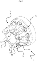
- a cutting tool 1 can be seen, wherein the cutting tool 1 is embodied as a milling tool by way of example.
- the cutting tool 1 has a drive member 2, a tool head 3 which is reversibly detachably placed on the drive member 2 and is made of steel, two driver elements 4 arranged diametrically with respect to one another and four damping elements 5, with the damping elements 5 being arranged in two pairs of two damping elements 5 lying opposite one another are.
- the driver elements 4 couple the tool head 3 to the drive member 2 so that the tool head 3 is rotated by the drive member 2 in a driven state of the drive member 2 about an inner axis of rotation 6 with respect to the drive member 2 .
- a relative rotation of the tool head from the tool head 3 to the drive member 2 is released with respect to the axis of rotation 6 and takes place with the driver elements 4 penetrating into the damping elements 5, which lie in the direction of the relative rotation of the tool head.
- the driver elements 4 are each arranged between two of the damping elements 5 in the circumferential direction with respect to the axis of rotation 6 .
- the relative tool head rotation means that the drive member 2 is stationary relative to the tool head 3 and the tool head 3 is rotated in one direction about the axis of rotation 6 .
- the relative tool head rotation can be clockwise or counterclockwise.
- the damping elements 5 deformed in the process absorb the impact energy occurring during milling as a result of discontinuous contact with the workpiece. Otherwise the driver elements 4 would strike undamped against the tool head 3 .
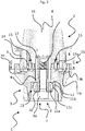
- the cutting tool 1 also has a locking device 7.
- the locking device 7 locks the tool head 3 in the axial direction with respect to the axis of rotation 6 against movement of the tool head 3 away from the drive member 2, in that the tool head 3 rests on a locking sleeve 8, the locking sleeve 8 on a screw head 9a of a screw 9 rests.
- a washer 10 is arranged between the screw 9 and the locking sleeve 8 to protect the screw head 9a.
- the screw 9 is screwed into the drive member 2 and is thus locked in the axial direction with respect to the axis of rotation 6 without the damping elements 5 being compressed as a result.
- the The locking sleeve 8, the screw 9 (including its screw head 9a) and the washer 10 are each part of the locking device 7.
- the locking device 7 is connected to the drive member 2 so that it can rotate synchronously with it.
- the locking sleeve 8 contacts the drive member 2 with a friction fit under a prestressing force applied by the screw 9, so that the locking sleeve 8 is connected to the drive member 2 so that it can rotate synchronously with it.
- the washer 10 contacts the screw head 9a and the locking sleeve 8 under the prestressing force applied by the screw 9 in each case by friction, so that the washer 10 is connected to the screw 9 and the locking sleeve 8 so that they can rotate synchronously.
- the locking device 7 only has the screw 9 (including its screw head 9a), after which the tool head 3 rests directly on the screw head 9a and is thus blocked against movement away from the drive member 2.
- the locking device 7 only has the screw 9 (including its screw head 9a) and the locking sleeve 8 .
- the cutting tool 1 also has a main pivot bearing unit 11.
- the main pivot bearing unit 11 ensures that the tool head 3 can be rotated relative to the locking device 7 under the relative tool head rotation. Without the main pivot unit 11, the relative tool head rotation by the drive member 2 would be constrained.
- the main rotary bearing unit 11 is designed as a tapered roller bearing, for example, and has an inner bearing ring 11a, an outer bearing ring 11b and a plurality of tapered rollers 11c which are arranged between the inner bearing ring 11a and the outer bearing ring 11b.
- the inner bearing ring 11a is carried by the locking sleeve 8 so that it can rotate synchronously with it.
- the outer bearing ring 11b is carried by the tool head 3 so that it can rotate synchronously with it. Under the relative rotation of the tool head, the inner bearing ring 11a is thus rotated about the axis of rotation 6 relative to the outer bearing ring 11b.
- the outer bearing ring 11b abuts against a radial projection 12 from the tool head 3 .
- the projection 12 thus serves as an abutment, which is axial with respect to the axis of rotation 6, for the outer bearing ring 11b.
- the cutting tool 1 also has a secondary pivot bearing unit 13.
- the secondary pivot bearing unit 13 is constructed analogously to the main pivot bearing unit 11. That is, the sub-pivot unit 13 has an inner race 13a, an outer race 13b, and a plurality of tapered rollers 13c interposed between the inner race 13a and the outer race 13b.
- the inner bearing ring 13a is connected to the drive member 2 so that it can rotate synchronously with it, in that the inner bearing ring 13a is supported by a support sleeve 14 so that it can rotate synchronously with it, the support sleeve 14 being supported by the drive member 2 so that it can rotate synchronously with it.
- the cutting tool 1 can also be designed without a carrier sleeve 14, after which the inner bearing ring 13a is carried by the drive member 2 so that it can rotate directly and synchronously and the outer bearing ring 13b is carried by the tool head 3 so that it can rotate synchronously.
- the cutting tool 1 it is also conceivable and also possible for the cutting tool 1 to be designed without the bearing rings 13a and 13b and without the carrier sleeve 14, after which the tapered rollers 11b or other rolling elements, for example rolling balls, are each located in a rolling element receptacle of the drive member 2 and the tool head 3 are mounted, wherein the rolling element seat on the part of the drive member 2 forms a monolithic unit with the drive member 2 and the rolling body seat on the side of the tool head 3 forms a monolithic unit with the tool head 3 .
- the tapered rollers 11b or other rolling elements for example rolling balls
- the main rotary bearing unit 11 and the secondary rotary bearing unit 13 are preloaded against one another in the axial direction with respect to the axis of rotation 6, the tapered rollers 11c and 13c being set and preloaded in accordance with an O arrangement with respect to one another.
- the main pivot bearing unit 11 and the secondary pivot bearing unit 13 are therefore under axial prestress.
- the axial preload is applied by the screw 9. The deeper the screw 9 is screwed into the drive member 2, the greater the axial preload and vice versa.
- the driver elements 4 are each connected by means of a screw 15 to the drive member 2 so that they can rotate synchronously and are axially locked with respect to the axis of rotation 6 .
- the driver elements 4 each maintain a gap to the tool head 3 that extends axially with respect to the axis of rotation 6 and protrude into the tool head 3 .
- the screws 15 each extend parallel to the axis of rotation 6 . However, it is also conceivable and also possible for the screws 15 to each extend perpendicularly to the axis of rotation 6 .
- the damping elements 5 are each L-shaped, with one leg, which can also be referred to as a projection, of the damping elements 5 being inserted into the drive member 2 in a form-fitting manner.
- the damping elements 5 each consist of an elastomer and are softer than the tool head 3, the driver elements 4 and the drive member 2.
- Damping elements 5 that have a different shape, e.g. B. T-shaped, double-T-shaped, U-shaped, O-shaped, V-shaped, D-shaped, I-shaped, M-shaped, Z-shaped or accordion-shaped.
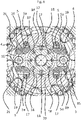
- the drive member 2 has a central coolant main channel 16 which has the axis of rotation 6 as its central axis and extends along the axis of rotation 6 .
- a plurality of secondary coolant channels 17 branch off from the main coolant channel 16 within the drive member 2 each extend along the axis of rotation 6 (in the figures 5 and 6 only one of the secondary coolant channels 17 is provided with the reference number 17).
- the secondary coolant channels 17 are in figure 6 those relating to the drawing plane and orientation of figure 6 coolant side channels 17 arranged at the 12 o'clock and 6 o'clock positions are fluidly connected to two curved branch channels 18 from the tool head 3 in each case.
- the coolant sub-channels 17 originally located at the 12 o'clock and 6 o'clock positions are rotated relative to the branch channels 18 and remain in fluid communication with the branch channels 18 up to a maximum rotational angle measured with respect to the axis of rotation 6 .
- the coolant sub-channels 17 originally arranged at the 12 o'clock and 6 o'clock positions no longer overlap with the branch channels 18.
- the damping elements 5 each have an internal coolant channel 5a, which is connected to one of the branch channels 18 in a fluid-communicating manner.
- the coolant channels 5a are also each connected in fluid communication with an outlet channel 19 of the tool head 3 .
- the outlet channels 19 each open into an annular gap 20 which is formed between the drive member 2 and the tool head 3 .
- a plurality of coolant outlets 21 branch off from the gap 20 in a fluid-communicating manner.
- the coolant outlets 21 are oriented such that the coolant can exit from each of the coolant outlets 21 with a flow direction component that is opposite to an intended direction of rotation 6a of the cutting tool 1 defined with respect to the axis of rotation 6 .
- the cutting elements can machine a workpiece, with chips being removed from a rake face by the cutting elements.
- the coolant reaches each receiving seat 3a of the tool head 3 with such a flow direction component. Cutting elements fastened in the receiving seats 3a are therefore cooled.
- the coolant is, for example, compressed air, after which the cutting tool 1 is suitable for dry cutting of a workpiece.
- other coolants for example liquid ones, are also conceivable and also possible.
- the receiving seats 3a are each designed and arranged to receive a cutting element (not shown).
- Each of the receiving seats 3a has a bore 3b for threadably receiving a fastening screw, not shown.
- the fastening screw can do this associated cutting element are reversibly releasably connected to its receiving seat 3a, so that the cutting element contacts a base 3c of the receiving seats 3a.
- the receiving seats 3a extend radially with respect to the axis of rotation 6 .
- the damping elements 5 are also supplied with the coolant, for example compressed air, by using the in figure 6 on the positions between the 12 o'clock and 3 o'clock positions, between the 3 o'clock and 6 o'clock positions, between the 6 o'clock and 9 o'clock positions and between the 9 o'clock and 12 o'clock positions Clock positions arranged coolant side channels 17 each flow out the coolant and so the damping elements 5 can each flow around.
- the coolant for example compressed air
- the tool head 3 is produced additively, which in particular enables the curved branch channels 18 to be shaped. However, a different production is also conceivable and also possible.
- the tool head 3 has a rounded notch 3d on the back of the receiving seats 3a, respectively, which widens the pressure angle of an assembly tool with respect to the attachment of the cutting elements.
- Cutting tool 1 shown is not limited.
- the cutting tool 1 it is conceivable and also possible for the cutting tool 1 to be designed without or with a different coolant channel structure.
- the receiving seats 3a it is also conceivable and also possible for the receiving seats 3a to extend differently, for example tangentially with respect to the axis of rotation 6 .
- the tool head 3 is formed from a hard metal (cemented carbide), after which the tool head 3 has at least one, preferably several cutting edges, the cutting edges forming a monolithic sintered unit with the tool head 3 .
- the locking device 7 is connected to the tool head 3 so that it can rotate synchronously and can accordingly rotate relative to the drive member 2 with respect to the axis of rotation 6 .
Landscapes
- Engineering & Computer Science (AREA)
- Mechanical Engineering (AREA)
- Milling Processes (AREA)
- Cutting Tools, Boring Holders, And Turrets (AREA)
Applications Claiming Priority (1)
| Application Number | Priority Date | Filing Date | Title |
|---|---|---|---|
| ATGM50101/2021U AT17718U1 (de) | 2021-05-05 | 2021-05-05 | Zerspanungswerkzeug |
Publications (1)
| Publication Number | Publication Date |
|---|---|
| EP4086026A1 true EP4086026A1 (fr) | 2022-11-09 |
Family
ID=81392593
Family Applications (1)
| Application Number | Title | Priority Date | Filing Date |
|---|---|---|---|
| EP22170401.8A Pending EP4086026A1 (fr) | 2021-05-05 | 2022-04-28 | Outil d'usinage par enlèvement des copeaux |
Country Status (2)
| Country | Link |
|---|---|
| EP (1) | EP4086026A1 (fr) |
| AT (1) | AT17718U1 (fr) |
Citations (2)
| Publication number | Priority date | Publication date | Assignee | Title |
|---|---|---|---|---|
| US3837758A (en) * | 1971-08-25 | 1974-09-24 | Tiefbohr Technik Gmbh | Means for damping vibrations of tools in drilling machines or the like |
| DE20203391U1 (de) | 2002-03-02 | 2003-07-17 | Trumpf Grüsch AG, Grüsch | Handfräsmaschine |
-
2021
- 2021-05-05 AT ATGM50101/2021U patent/AT17718U1/de unknown
-
2022
- 2022-04-28 EP EP22170401.8A patent/EP4086026A1/fr active Pending
Patent Citations (2)
| Publication number | Priority date | Publication date | Assignee | Title |
|---|---|---|---|---|
| US3837758A (en) * | 1971-08-25 | 1974-09-24 | Tiefbohr Technik Gmbh | Means for damping vibrations of tools in drilling machines or the like |
| DE20203391U1 (de) | 2002-03-02 | 2003-07-17 | Trumpf Grüsch AG, Grüsch | Handfräsmaschine |
Also Published As
| Publication number | Publication date |
|---|---|
| AT17718U1 (de) | 2022-12-15 |
Similar Documents
| Publication | Publication Date | Title |
|---|---|---|
| EP0964764B1 (fr) | Outil de coupe pour alesage et chanfreinage | |
| EP2323792B1 (fr) | Outil de perçage à arêtes coupantes multiples | |
| DE102013105171B3 (de) | Vorspannendes Dämpfungssystem | |
| DE69309607T2 (de) | Aus Diamant bestehender Lagerzusammenbau | |
| EP1924377B1 (fr) | Porte-outil exempt de vibrations | |
| EP2318166B1 (fr) | Outil pour l'usinage par enlèvement de copeaux d'une pièce à usiner | |
| EP2815139B1 (fr) | Palier radial | |
| EP2603340B1 (fr) | Porte-outil | |
| DE202012100353U1 (de) | Werkzeughalterung zur Montage eines Meißelwerkzeugs | |
| DE102011102563B4 (de) | Werkzeugadapter mit einem Halter | |
| WO2012013425A1 (fr) | Outil pour le rodage de positionnement | |
| DE1402910A1 (de) | Exzentrischer Bohrkopf | |
| DE112010003521B4 (de) | Bohrmeißel | |
| DE2824070B2 (de) | Lageranordnung für dichtungslose Drehbohrkronen | |
| DE102007048111A1 (de) | Rotierendes spanabhebendes Werkzeug | |
| DE102007015421A1 (de) | Axial-Schrägwälzlager, insbesondere zur Rundtischlagerung an Werkzeugmaschinen | |
| DE102012212677B4 (de) | Honwerkzeug, insbesondere zum Positionshonen | |
| DE3545438A1 (de) | Kegelrollenmeissel | |
| AT17718U1 (de) | Zerspanungswerkzeug | |
| DE102015225803B4 (de) | Honwerkzeug | |
| AT413047B (de) | Träger für eine fliegende schneiddiskenlagerung | |
| EP1631733B1 (fr) | Element de retenue de burin a tige cylindrique pour une fraiseuse | |
| DE102005051695A1 (de) | Fräs- und/oder Drehwerkzeug sowie Fräs- und/oder Drehverfahren | |
| EP2944836B1 (fr) | Palier à roulement | |
| DE102019216495B4 (de) | Lageranordnung für die Lagerung eines Bohrkopfes in einer Tunnelbohrmaschine und Tunnelbohrmaschine |
Legal Events
| Date | Code | Title | Description |
|---|---|---|---|
| PUAI | Public reference made under article 153(3) epc to a published international application that has entered the european phase |
Free format text: ORIGINAL CODE: 0009012 |
|
| STAA | Information on the status of an ep patent application or granted ep patent |
Free format text: STATUS: THE APPLICATION HAS BEEN PUBLISHED |
|
| AK | Designated contracting states |
Kind code of ref document: A1 Designated state(s): AL AT BE BG CH CY CZ DE DK EE ES FI FR GB GR HR HU IE IS IT LI LT LU LV MC MK MT NL NO PL PT RO RS SE SI SK SM TR |
|
| STAA | Information on the status of an ep patent application or granted ep patent |
Free format text: STATUS: REQUEST FOR EXAMINATION WAS MADE |
|
| 17P | Request for examination filed |
Effective date: 20230427 |
|
| RBV | Designated contracting states (corrected) |
Designated state(s): AL AT BE BG CH CY CZ DE DK EE ES FI FR GB GR HR HU IE IS IT LI LT LU LV MC MK MT NL NO PL PT RO RS SE SI SK SM TR |