EP4086094B1 - Système de gestion thermique et véhicule électrique - Google Patents
Système de gestion thermique et véhicule électrique Download PDFInfo
- Publication number
- EP4086094B1 EP4086094B1 EP20913314.9A EP20913314A EP4086094B1 EP 4086094 B1 EP4086094 B1 EP 4086094B1 EP 20913314 A EP20913314 A EP 20913314A EP 4086094 B1 EP4086094 B1 EP 4086094B1
- Authority
- EP
- European Patent Office
- Prior art keywords
- valve port
- valve
- open state
- path direction
- direction control
- Prior art date
- Legal status (The legal status is an assumption and is not a legal conclusion. Google has not performed a legal analysis and makes no representation as to the accuracy of the status listed.)
- Active
Links
Images




Classifications
-
- B—PERFORMING OPERATIONS; TRANSPORTING
- B60—VEHICLES IN GENERAL
- B60K—ARRANGEMENT OR MOUNTING OF PROPULSION UNITS OR OF TRANSMISSIONS IN VEHICLES; ARRANGEMENT OR MOUNTING OF PLURAL DIVERSE PRIME-MOVERS IN VEHICLES; AUXILIARY DRIVES FOR VEHICLES; INSTRUMENTATION OR DASHBOARDS FOR VEHICLES; ARRANGEMENTS IN CONNECTION WITH COOLING, AIR INTAKE, GAS EXHAUST OR FUEL SUPPLY OF PROPULSION UNITS IN VEHICLES
- B60K11/00—Arrangement in connection with cooling of propulsion units
- B60K11/02—Arrangement in connection with cooling of propulsion units with liquid cooling
-
- B—PERFORMING OPERATIONS; TRANSPORTING
- B60—VEHICLES IN GENERAL
- B60H—ARRANGEMENTS OF HEATING, COOLING, VENTILATING OR OTHER AIR-TREATING DEVICES SPECIALLY ADAPTED FOR PASSENGER OR GOODS SPACES OF VEHICLES
- B60H1/00—Heating, cooling or ventilating devices
- B60H1/00271—HVAC devices specially adapted for particular vehicle parts or components and being connected to the vehicle HVAC unit
- B60H1/00278—HVAC devices specially adapted for particular vehicle parts or components and being connected to the vehicle HVAC unit for the battery
-
- B—PERFORMING OPERATIONS; TRANSPORTING
- B60—VEHICLES IN GENERAL
- B60H—ARRANGEMENTS OF HEATING, COOLING, VENTILATING OR OTHER AIR-TREATING DEVICES SPECIALLY ADAPTED FOR PASSENGER OR GOODS SPACES OF VEHICLES
- B60H1/00—Heating, cooling or ventilating devices
- B60H1/00357—Air-conditioning arrangements specially adapted for particular vehicles
- B60H1/00385—Air-conditioning arrangements specially adapted for particular vehicles for vehicles having an electrical drive, e.g. hybrid or fuel cell
- B60H1/00392—Air-conditioning arrangements specially adapted for particular vehicles for vehicles having an electrical drive, e.g. hybrid or fuel cell for electric vehicles having only electric drive means
-
- B—PERFORMING OPERATIONS; TRANSPORTING
- B60—VEHICLES IN GENERAL
- B60H—ARRANGEMENTS OF HEATING, COOLING, VENTILATING OR OTHER AIR-TREATING DEVICES SPECIALLY ADAPTED FOR PASSENGER OR GOODS SPACES OF VEHICLES
- B60H1/00—Heating, cooling or ventilating devices
- B60H1/00485—Valves for air-conditioning devices, e.g. thermostatic valves
-
- B—PERFORMING OPERATIONS; TRANSPORTING
- B60—VEHICLES IN GENERAL
- B60H—ARRANGEMENTS OF HEATING, COOLING, VENTILATING OR OTHER AIR-TREATING DEVICES SPECIALLY ADAPTED FOR PASSENGER OR GOODS SPACES OF VEHICLES
- B60H1/00—Heating, cooling or ventilating devices
- B60H1/00642—Control systems or circuits; Control members or indication devices for heating, cooling or ventilating devices
- B60H1/00814—Control systems or circuits characterised by their output, for controlling particular components of the heating, cooling or ventilating installation
- B60H1/00878—Control systems or circuits characterised by their output, for controlling particular components of the heating, cooling or ventilating installation the components being temperature regulating devices
- B60H1/00885—Controlling the flow of heating or cooling liquid, e.g. valves or pumps
-
- B—PERFORMING OPERATIONS; TRANSPORTING
- B60—VEHICLES IN GENERAL
- B60H—ARRANGEMENTS OF HEATING, COOLING, VENTILATING OR OTHER AIR-TREATING DEVICES SPECIALLY ADAPTED FOR PASSENGER OR GOODS SPACES OF VEHICLES
- B60H1/00—Heating, cooling or ventilating devices
- B60H1/22—Heating, cooling or ventilating devices the heat source being other than the propulsion plant
- B60H1/2215—Heating, cooling or ventilating devices the heat source being other than the propulsion plant the heat being derived from electric heaters
- B60H1/2221—Heating, cooling or ventilating devices the heat source being other than the propulsion plant the heat being derived from electric heaters arrangements of electric heaters for heating an intermediate liquid
-
- B—PERFORMING OPERATIONS; TRANSPORTING
- B60—VEHICLES IN GENERAL
- B60H—ARRANGEMENTS OF HEATING, COOLING, VENTILATING OR OTHER AIR-TREATING DEVICES SPECIALLY ADAPTED FOR PASSENGER OR GOODS SPACES OF VEHICLES
- B60H1/00—Heating, cooling or ventilating devices
- B60H1/32—Cooling devices
- B60H1/3204—Cooling devices using compression
- B60H1/3228—Cooling devices using compression characterised by refrigerant circuit configurations
- B60H1/32284—Cooling devices using compression characterised by refrigerant circuit configurations comprising two or more secondary circuits, e.g. at evaporator and condenser side
-
- B—PERFORMING OPERATIONS; TRANSPORTING
- B60—VEHICLES IN GENERAL
- B60K—ARRANGEMENT OR MOUNTING OF PROPULSION UNITS OR OF TRANSMISSIONS IN VEHICLES; ARRANGEMENT OR MOUNTING OF PLURAL DIVERSE PRIME-MOVERS IN VEHICLES; AUXILIARY DRIVES FOR VEHICLES; INSTRUMENTATION OR DASHBOARDS FOR VEHICLES; ARRANGEMENTS IN CONNECTION WITH COOLING, AIR INTAKE, GAS EXHAUST OR FUEL SUPPLY OF PROPULSION UNITS IN VEHICLES
- B60K1/00—Arrangement or mounting of electrical propulsion units
-
- B—PERFORMING OPERATIONS; TRANSPORTING
- B60—VEHICLES IN GENERAL
- B60L—PROPULSION OF ELECTRICALLY-PROPELLED VEHICLES; SUPPLYING ELECTRIC POWER FOR AUXILIARY EQUIPMENT OF ELECTRICALLY-PROPELLED VEHICLES; ELECTRODYNAMIC BRAKE SYSTEMS FOR VEHICLES IN GENERAL; MAGNETIC SUSPENSION OR LEVITATION FOR VEHICLES; MONITORING OPERATING VARIABLES OF ELECTRICALLY-PROPELLED VEHICLES; ELECTRIC SAFETY DEVICES FOR ELECTRICALLY-PROPELLED VEHICLES
- B60L1/00—Supplying electric power to auxiliary equipment of vehicles
- B60L1/003—Supplying electric power to auxiliary equipment of vehicles to auxiliary motors, e.g. for pumps, compressors
-
- B—PERFORMING OPERATIONS; TRANSPORTING
- B60—VEHICLES IN GENERAL
- B60L—PROPULSION OF ELECTRICALLY-PROPELLED VEHICLES; SUPPLYING ELECTRIC POWER FOR AUXILIARY EQUIPMENT OF ELECTRICALLY-PROPELLED VEHICLES; ELECTRODYNAMIC BRAKE SYSTEMS FOR VEHICLES IN GENERAL; MAGNETIC SUSPENSION OR LEVITATION FOR VEHICLES; MONITORING OPERATING VARIABLES OF ELECTRICALLY-PROPELLED VEHICLES; ELECTRIC SAFETY DEVICES FOR ELECTRICALLY-PROPELLED VEHICLES
- B60L1/00—Supplying electric power to auxiliary equipment of vehicles
- B60L1/02—Supplying electric power to auxiliary equipment of vehicles to electric heating circuits
-
- B—PERFORMING OPERATIONS; TRANSPORTING
- B60—VEHICLES IN GENERAL
- B60L—PROPULSION OF ELECTRICALLY-PROPELLED VEHICLES; SUPPLYING ELECTRIC POWER FOR AUXILIARY EQUIPMENT OF ELECTRICALLY-PROPELLED VEHICLES; ELECTRODYNAMIC BRAKE SYSTEMS FOR VEHICLES IN GENERAL; MAGNETIC SUSPENSION OR LEVITATION FOR VEHICLES; MONITORING OPERATING VARIABLES OF ELECTRICALLY-PROPELLED VEHICLES; ELECTRIC SAFETY DEVICES FOR ELECTRICALLY-PROPELLED VEHICLES
- B60L58/00—Methods or circuit arrangements for monitoring or controlling batteries or fuel cells, specially adapted for electric vehicles
- B60L58/10—Methods or circuit arrangements for monitoring or controlling batteries or fuel cells, specially adapted for electric vehicles for monitoring or controlling batteries
- B60L58/24—Methods or circuit arrangements for monitoring or controlling batteries or fuel cells, specially adapted for electric vehicles for monitoring or controlling batteries for controlling the temperature of batteries
- B60L58/26—Methods or circuit arrangements for monitoring or controlling batteries or fuel cells, specially adapted for electric vehicles for monitoring or controlling batteries for controlling the temperature of batteries by cooling
-
- B—PERFORMING OPERATIONS; TRANSPORTING
- B60—VEHICLES IN GENERAL
- B60L—PROPULSION OF ELECTRICALLY-PROPELLED VEHICLES; SUPPLYING ELECTRIC POWER FOR AUXILIARY EQUIPMENT OF ELECTRICALLY-PROPELLED VEHICLES; ELECTRODYNAMIC BRAKE SYSTEMS FOR VEHICLES IN GENERAL; MAGNETIC SUSPENSION OR LEVITATION FOR VEHICLES; MONITORING OPERATING VARIABLES OF ELECTRICALLY-PROPELLED VEHICLES; ELECTRIC SAFETY DEVICES FOR ELECTRICALLY-PROPELLED VEHICLES
- B60L58/00—Methods or circuit arrangements for monitoring or controlling batteries or fuel cells, specially adapted for electric vehicles
- B60L58/10—Methods or circuit arrangements for monitoring or controlling batteries or fuel cells, specially adapted for electric vehicles for monitoring or controlling batteries
- B60L58/24—Methods or circuit arrangements for monitoring or controlling batteries or fuel cells, specially adapted for electric vehicles for monitoring or controlling batteries for controlling the temperature of batteries
- B60L58/27—Methods or circuit arrangements for monitoring or controlling batteries or fuel cells, specially adapted for electric vehicles for monitoring or controlling batteries for controlling the temperature of batteries by heating
-
- F—MECHANICAL ENGINEERING; LIGHTING; HEATING; WEAPONS; BLASTING
- F25—REFRIGERATION OR COOLING; COMBINED HEATING AND REFRIGERATION SYSTEMS; HEAT PUMP SYSTEMS; MANUFACTURE OR STORAGE OF ICE; LIQUEFACTION SOLIDIFICATION OF GASES
- F25B—REFRIGERATION MACHINES, PLANTS OR SYSTEMS; COMBINED HEATING AND REFRIGERATION SYSTEMS; HEAT PUMP SYSTEMS
- F25B25/00—Machines, plants or systems, using a combination of modes of operation covered by two or more of the groups F25B1/00 - F25B23/00
- F25B25/005—Machines, plants or systems, using a combination of modes of operation covered by two or more of the groups F25B1/00 - F25B23/00 using primary and secondary systems
-
- H—ELECTRICITY
- H01—ELECTRIC ELEMENTS
- H01M—PROCESSES OR MEANS, e.g. BATTERIES, FOR THE DIRECT CONVERSION OF CHEMICAL ENERGY INTO ELECTRICAL ENERGY
- H01M10/00—Secondary cells; Manufacture thereof
- H01M10/60—Heating or cooling; Temperature control
- H01M10/62—Heating or cooling; Temperature control specially adapted for specific applications
- H01M10/625—Vehicles
-
- H—ELECTRICITY
- H01—ELECTRIC ELEMENTS
- H01M—PROCESSES OR MEANS, e.g. BATTERIES, FOR THE DIRECT CONVERSION OF CHEMICAL ENERGY INTO ELECTRICAL ENERGY
- H01M10/00—Secondary cells; Manufacture thereof
- H01M10/60—Heating or cooling; Temperature control
- H01M10/63—Control systems
-
- H—ELECTRICITY
- H01—ELECTRIC ELEMENTS
- H01M—PROCESSES OR MEANS, e.g. BATTERIES, FOR THE DIRECT CONVERSION OF CHEMICAL ENERGY INTO ELECTRICAL ENERGY
- H01M10/00—Secondary cells; Manufacture thereof
- H01M10/60—Heating or cooling; Temperature control
- H01M10/65—Means for temperature control structurally associated with the cells
- H01M10/656—Means for temperature control structurally associated with the cells characterised by the type of heat-exchange fluid
- H01M10/6561—Gases
- H01M10/6563—Gases with forced flow, e.g. by blowers
-
- H—ELECTRICITY
- H01—ELECTRIC ELEMENTS
- H01M—PROCESSES OR MEANS, e.g. BATTERIES, FOR THE DIRECT CONVERSION OF CHEMICAL ENERGY INTO ELECTRICAL ENERGY
- H01M10/00—Secondary cells; Manufacture thereof
- H01M10/60—Heating or cooling; Temperature control
- H01M10/65—Means for temperature control structurally associated with the cells
- H01M10/656—Means for temperature control structurally associated with the cells characterised by the type of heat-exchange fluid
- H01M10/6567—Liquids
-
- H—ELECTRICITY
- H01—ELECTRIC ELEMENTS
- H01M—PROCESSES OR MEANS, e.g. BATTERIES, FOR THE DIRECT CONVERSION OF CHEMICAL ENERGY INTO ELECTRICAL ENERGY
- H01M10/00—Secondary cells; Manufacture thereof
- H01M10/60—Heating or cooling; Temperature control
- H01M10/65—Means for temperature control structurally associated with the cells
- H01M10/656—Means for temperature control structurally associated with the cells characterised by the type of heat-exchange fluid
- H01M10/6569—Fluids undergoing a liquid-gas phase change or transition, e.g. evaporation or condensation
-
- H—ELECTRICITY
- H01—ELECTRIC ELEMENTS
- H01M—PROCESSES OR MEANS, e.g. BATTERIES, FOR THE DIRECT CONVERSION OF CHEMICAL ENERGY INTO ELECTRICAL ENERGY
- H01M10/00—Secondary cells; Manufacture thereof
- H01M10/60—Heating or cooling; Temperature control
- H01M10/65—Means for temperature control structurally associated with the cells
- H01M10/659—Means for temperature control structurally associated with the cells by heat storage or buffering, e.g. heat capacity or liquid-solid phase changes or transition
-
- H—ELECTRICITY
- H01—ELECTRIC ELEMENTS
- H01M—PROCESSES OR MEANS, e.g. BATTERIES, FOR THE DIRECT CONVERSION OF CHEMICAL ENERGY INTO ELECTRICAL ENERGY
- H01M10/00—Secondary cells; Manufacture thereof
- H01M10/60—Heating or cooling; Temperature control
- H01M10/66—Heat-exchange relationships between the cells and other systems, e.g. central heating systems or fuel cells
-
- B—PERFORMING OPERATIONS; TRANSPORTING
- B60—VEHICLES IN GENERAL
- B60H—ARRANGEMENTS OF HEATING, COOLING, VENTILATING OR OTHER AIR-TREATING DEVICES SPECIALLY ADAPTED FOR PASSENGER OR GOODS SPACES OF VEHICLES
- B60H1/00—Heating, cooling or ventilating devices
- B60H1/00271—HVAC devices specially adapted for particular vehicle parts or components and being connected to the vehicle HVAC unit
- B60H2001/00307—Component temperature regulation using a liquid flow
-
- B—PERFORMING OPERATIONS; TRANSPORTING
- B60—VEHICLES IN GENERAL
- B60K—ARRANGEMENT OR MOUNTING OF PROPULSION UNITS OR OF TRANSMISSIONS IN VEHICLES; ARRANGEMENT OR MOUNTING OF PLURAL DIVERSE PRIME-MOVERS IN VEHICLES; AUXILIARY DRIVES FOR VEHICLES; INSTRUMENTATION OR DASHBOARDS FOR VEHICLES; ARRANGEMENTS IN CONNECTION WITH COOLING, AIR INTAKE, GAS EXHAUST OR FUEL SUPPLY OF PROPULSION UNITS IN VEHICLES
- B60K1/00—Arrangement or mounting of electrical propulsion units
- B60K2001/003—Arrangement or mounting of electrical propulsion units with means for cooling the electrical propulsion units
-
- B—PERFORMING OPERATIONS; TRANSPORTING
- B60—VEHICLES IN GENERAL
- B60K—ARRANGEMENT OR MOUNTING OF PROPULSION UNITS OR OF TRANSMISSIONS IN VEHICLES; ARRANGEMENT OR MOUNTING OF PLURAL DIVERSE PRIME-MOVERS IN VEHICLES; AUXILIARY DRIVES FOR VEHICLES; INSTRUMENTATION OR DASHBOARDS FOR VEHICLES; ARRANGEMENTS IN CONNECTION WITH COOLING, AIR INTAKE, GAS EXHAUST OR FUEL SUPPLY OF PROPULSION UNITS IN VEHICLES
- B60K1/00—Arrangement or mounting of electrical propulsion units
- B60K2001/003—Arrangement or mounting of electrical propulsion units with means for cooling the electrical propulsion units
- B60K2001/005—Arrangement or mounting of electrical propulsion units with means for cooling the electrical propulsion units the electric storage means
-
- B—PERFORMING OPERATIONS; TRANSPORTING
- B60—VEHICLES IN GENERAL
- B60K—ARRANGEMENT OR MOUNTING OF PROPULSION UNITS OR OF TRANSMISSIONS IN VEHICLES; ARRANGEMENT OR MOUNTING OF PLURAL DIVERSE PRIME-MOVERS IN VEHICLES; AUXILIARY DRIVES FOR VEHICLES; INSTRUMENTATION OR DASHBOARDS FOR VEHICLES; ARRANGEMENTS IN CONNECTION WITH COOLING, AIR INTAKE, GAS EXHAUST OR FUEL SUPPLY OF PROPULSION UNITS IN VEHICLES
- B60K1/00—Arrangement or mounting of electrical propulsion units
- B60K2001/003—Arrangement or mounting of electrical propulsion units with means for cooling the electrical propulsion units
- B60K2001/006—Arrangement or mounting of electrical propulsion units with means for cooling the electrical propulsion units the electric motors
-
- B—PERFORMING OPERATIONS; TRANSPORTING
- B60—VEHICLES IN GENERAL
- B60L—PROPULSION OF ELECTRICALLY-PROPELLED VEHICLES; SUPPLYING ELECTRIC POWER FOR AUXILIARY EQUIPMENT OF ELECTRICALLY-PROPELLED VEHICLES; ELECTRODYNAMIC BRAKE SYSTEMS FOR VEHICLES IN GENERAL; MAGNETIC SUSPENSION OR LEVITATION FOR VEHICLES; MONITORING OPERATING VARIABLES OF ELECTRICALLY-PROPELLED VEHICLES; ELECTRIC SAFETY DEVICES FOR ELECTRICALLY-PROPELLED VEHICLES
- B60L2240/00—Control parameters of input or output; Target parameters
- B60L2240/10—Vehicle control parameters
- B60L2240/36—Temperature of vehicle components or parts
-
- B—PERFORMING OPERATIONS; TRANSPORTING
- B60—VEHICLES IN GENERAL
- B60L—PROPULSION OF ELECTRICALLY-PROPELLED VEHICLES; SUPPLYING ELECTRIC POWER FOR AUXILIARY EQUIPMENT OF ELECTRICALLY-PROPELLED VEHICLES; ELECTRODYNAMIC BRAKE SYSTEMS FOR VEHICLES IN GENERAL; MAGNETIC SUSPENSION OR LEVITATION FOR VEHICLES; MONITORING OPERATING VARIABLES OF ELECTRICALLY-PROPELLED VEHICLES; ELECTRIC SAFETY DEVICES FOR ELECTRICALLY-PROPELLED VEHICLES
- B60L2240/00—Control parameters of input or output; Target parameters
- B60L2240/40—Drive Train control parameters
- B60L2240/54—Drive Train control parameters related to batteries
- B60L2240/545—Temperature
-
- F—MECHANICAL ENGINEERING; LIGHTING; HEATING; WEAPONS; BLASTING
- F25—REFRIGERATION OR COOLING; COMBINED HEATING AND REFRIGERATION SYSTEMS; HEAT PUMP SYSTEMS; MANUFACTURE OR STORAGE OF ICE; LIQUEFACTION SOLIDIFICATION OF GASES
- F25B—REFRIGERATION MACHINES, PLANTS OR SYSTEMS; COMBINED HEATING AND REFRIGERATION SYSTEMS; HEAT PUMP SYSTEMS
- F25B2339/00—Details of evaporators; Details of condensers
- F25B2339/04—Details of condensers
- F25B2339/047—Water-cooled condensers
-
- H—ELECTRICITY
- H01—ELECTRIC ELEMENTS
- H01M—PROCESSES OR MEANS, e.g. BATTERIES, FOR THE DIRECT CONVERSION OF CHEMICAL ENERGY INTO ELECTRICAL ENERGY
- H01M2220/00—Batteries for particular applications
- H01M2220/20—Batteries in motive systems, e.g. vehicle, ship, plane
-
- Y—GENERAL TAGGING OF NEW TECHNOLOGICAL DEVELOPMENTS; GENERAL TAGGING OF CROSS-SECTIONAL TECHNOLOGIES SPANNING OVER SEVERAL SECTIONS OF THE IPC; TECHNICAL SUBJECTS COVERED BY FORMER USPC CROSS-REFERENCE ART COLLECTIONS [XRACs] AND DIGESTS
- Y02—TECHNOLOGIES OR APPLICATIONS FOR MITIGATION OR ADAPTATION AGAINST CLIMATE CHANGE
- Y02E—REDUCTION OF GREENHOUSE GAS [GHG] EMISSIONS, RELATED TO ENERGY GENERATION, TRANSMISSION OR DISTRIBUTION
- Y02E60/00—Enabling technologies; Technologies with a potential or indirect contribution to GHG emissions mitigation
- Y02E60/10—Energy storage using batteries
-
- Y—GENERAL TAGGING OF NEW TECHNOLOGICAL DEVELOPMENTS; GENERAL TAGGING OF CROSS-SECTIONAL TECHNOLOGIES SPANNING OVER SEVERAL SECTIONS OF THE IPC; TECHNICAL SUBJECTS COVERED BY FORMER USPC CROSS-REFERENCE ART COLLECTIONS [XRACs] AND DIGESTS
- Y02—TECHNOLOGIES OR APPLICATIONS FOR MITIGATION OR ADAPTATION AGAINST CLIMATE CHANGE
- Y02T—CLIMATE CHANGE MITIGATION TECHNOLOGIES RELATED TO TRANSPORTATION
- Y02T10/00—Road transport of goods or passengers
- Y02T10/60—Other road transportation technologies with climate change mitigation effect
- Y02T10/70—Energy storage systems for electromobility, e.g. batteries
-
- Y—GENERAL TAGGING OF NEW TECHNOLOGICAL DEVELOPMENTS; GENERAL TAGGING OF CROSS-SECTIONAL TECHNOLOGIES SPANNING OVER SEVERAL SECTIONS OF THE IPC; TECHNICAL SUBJECTS COVERED BY FORMER USPC CROSS-REFERENCE ART COLLECTIONS [XRACs] AND DIGESTS
- Y02—TECHNOLOGIES OR APPLICATIONS FOR MITIGATION OR ADAPTATION AGAINST CLIMATE CHANGE
- Y02T—CLIMATE CHANGE MITIGATION TECHNOLOGIES RELATED TO TRANSPORTATION
- Y02T10/00—Road transport of goods or passengers
- Y02T10/60—Other road transportation technologies with climate change mitigation effect
- Y02T10/72—Electric energy management in electromobility
-
- Y—GENERAL TAGGING OF NEW TECHNOLOGICAL DEVELOPMENTS; GENERAL TAGGING OF CROSS-SECTIONAL TECHNOLOGIES SPANNING OVER SEVERAL SECTIONS OF THE IPC; TECHNICAL SUBJECTS COVERED BY FORMER USPC CROSS-REFERENCE ART COLLECTIONS [XRACs] AND DIGESTS
- Y02—TECHNOLOGIES OR APPLICATIONS FOR MITIGATION OR ADAPTATION AGAINST CLIMATE CHANGE
- Y02T—CLIMATE CHANGE MITIGATION TECHNOLOGIES RELATED TO TRANSPORTATION
- Y02T10/00—Road transport of goods or passengers
- Y02T10/80—Technologies aiming to reduce greenhouse gasses emissions common to all road transportation technologies
- Y02T10/88—Optimized components or subsystems, e.g. lighting, actively controlled glasses
Definitions
- This application relates to the field of heat management technologies, and in particular, to a heat management system and an electronic vehicle.
- an electric vehicle uses a battery as a power source, and therefore has features such as energy conservation and environmental protection.
- a pure electric vehicle is popularized in the market.
- heat management generally needs to be performed on management objects such as a battery pack, a passenger compartment, and a power system (which may also be referred to as a power assembly) of the electric vehicle, so that temperatures of these management objects are maintained within an operating temperature range for normal operation.
- the heat management includes cooling management and heating management.
- the power system may include but is not limited to an oil cooler, a motor, and a power component (such as an inverter).
- FIG. 1 a conventional heat management architecture solution of an electric vehicle is shown in FIG. 1 .
- the conventional heat management solution is divided into three circulation parts based on endurance temperatures of three system ends of the battery pack, the passenger compartment, and the power assembly.
- Circulation 1 is heat dissipation circulation of the battery pack (an intake temperature of a low-temperature heat exchanger of a battery at a front end is about 30°C).
- Circulation 2 is cooling circulation of the passenger compartment (an intake temperature of a condenser is about 40°C).
- Circulation 3 is heat dissipation circulation of a power assembly loop (an intake temperature of a heat sink of the power assembly at a front end is about 45°C).
- US 2018/0208014 A1 describes a waste heat utilization system for an electric vehicle having an electric motor and a battery may include a first cooling circuit in which a first coolant circulates and having arranged therein the electric motor, a first direct heat exchanger for discharging heat from the first coolant into surroundings of the system, and a first delivery device for driving the first coolant.
- the system may also include a second cooling circuit in which a second coolant circulates and having arranged therein the battery and a second delivery device for driving the second coolant.
- the system may also include an air conditioning circuit in which a working medium circulates, and having arranged therein a compressor, condenser, and evaporator.
- the system may further include first and second chillers by which heat may be transferrable from the first and second cooling circuits into the air conditioning circuit, and first and second heat exchangers incorporated in one of the first and second cooling circuits for discharging heat into the surroundings.
- CN110329113A describes a control method for automobile comprehensive thermal management.
- Embodiments of this invention provide a heat management system and an electric vehicle, to provide specific coolant circulation manners (that is, heat management manners) for different heat management requirements, thereby reducing energy consumption and costs generated when a system performs heat management on a power assembly and a battery pack.
- the embodiments of this invention provide a heat management system and an electric vehicle, to provide specific coolant circulation manners (that is, heat management manners) for different heat management requirements, thereby reducing energy consumption and costs generated when a system performs heat management on a power assembly and a battery pack.
- this invention provides a heat management system (hereinafter referred to as a system for short).
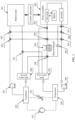
- a system for short For a framework of the system, refer to FIG. 2 .
- the system includes a vapor compression circulation subsystem and a coolant subsystem.
- the vapor compression circulation subsystem is connected by using a dashed line.
- the subsystem includes but is not limited to the following components: a compressor 101, a condenser 102 (for example, a water condenser), a throttling apparatus 103 (for example, a regulating valve), and an evaporator 104 (for example, a water evaporator).
- the compressor 101, the condenser 102, the throttling apparatus 103, and the evaporator 104 are sequentially connected to form a closed loop shown by using the dashed line in FIG. 2 .
- the vapor compression circulation subsystem is configured to: control a temperature and a velocity of a coolant in the condenser 102 and/or the evaporator 103, and then provide the coolant with a preset temperature to the coolant subsystem. For example, if the compressor 101 operates, the coolant circulates in the closed loop shown by using the dashed line in FIG. 2 .
- the system includes but is not limited to the following components: a first water pump 201 (that is, a condenser branch water pump), a battery pack 202, a power assembly 203, a second water pump 204 (that is, a power assembly branch water pump), a heat exchanger 205, a third water pump 206 (that is, an evaporator branch water pump), a first water tank 207 (for example, an evaporator expansion water tank), a second water tank 208 (for example, a condenser expansion water tank), and a multi-path direction control valve assembly (for example, multi-path direction control valves 301 to 309 in FIG. 2 ).
- a first water pump 201 that is, a condenser branch water pump
- a battery pack 202 that is, a power assembly 203, a second water pump 204 (that is, a power assembly branch water pump), a heat exchanger 205, a third water pump 206 (that is, an evaporator branch water pump),
- the second water tank 208, the power assembly 203, and a third valve port of the multi-path direction control valve 305 are respectively connected to a first valve port, a third valve port, and a second valve port of a multi-path direction control valve 304 of the multi-path direction control valve assembly.
- a water inlet of the heat exchanger 205 and a second valve port of a multi-path direction control valve 309 of the multi-path direction control valve assembly are respectively connected to a first valve port and a second valve port of the multi-path direction control valve 305.
- the second water tank 208, the first water tank 207, a water outlet of the heat exchanger 205, and the second water pump 204 are respectively connected to a fourth valve port, a first valve port, a third valve port, and a second valve port of a multi-path direction control valve 306 of the multi-path direction control valve assembly.
- the power assembly 203, the second water pump 204, and a right valve of a multi-path direction control valve 308 are respectively connected to a third valve port, a second valve port, and a first valve port of a multi-path direction control valve 307 of the multi-path direction control valve assembly.
- a third valve port of the multi-path direction control valve 309 is connected to a first valve port of the multi-path direction control valve 308.
- the third water pump 206 is connected to a first valve port of the multi-path direction control valve 309.
- the system further includes a control subsystem.
- the control subsystem specifically controls the multi-path direction control valve assembly to implement circulation of the coolant among the condenser 102, the evaporator 104, the battery pack 202, the power assembly 203, the heat exchanger 205, the first water pump 201, the second water pump 204, the third water pump 206, the first water tank 207, and the second water tank 208.
- the multi-path direction control valve assembly includes the plurality of multi-path direction control valves.
- the multi-path direction control valves may be in different types such as a two-path direction control valve, a three-path direction control valve, and a four-path direction control valve. Different types of multi-path direction control valves also have different quantities of valves. Therefore, the control subsystem can control opening or closing of each valve port to select different circulation manners of the coolant. This includes but is not limited to the following manners.
- the system further includes a sensing subsystem configured to obtain a heat parameter of a target object.
- the target object includes one or more of an environment in which the system is located, the battery pack, and the power assembly.
- the control subsystem is further specifically configured to: receive the heat parameter sent by the sensing subsystem, and control, based on the heat parameter, opening or closing of a valve port of each multi-path direction control valve of the multi-path direction control valve assembly.
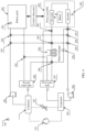
- the sensing subsystem includes but is not limited to the following components (with reference to FIG. 4 ): a first sensor 401 (for example, a temperature sensor configured to sense a first temperature of the battery pack 202), a second sensor 402 (for example, a heat sensor configured to sense a heat value generated when the power assembly 203 is in different operation states), and a third sensor 403 (for example, a temperature sensor configured to sense a second temperature of the environment in which the system is located).
- the sensing subsystem is configured to obtain the heat parameter (for example, the temperature or the heat value) of the target object (for example, the battery pack 202, the power assembly 203, or the environment in which the system is located).
- control subsystem may be further configured to: obtain a current operating condition (for example, a normally driving condition, a fast charging request, or a start condition) of the electric vehicle configured with the system, and control, based on the obtained heat parameter of the target object, the coolant subsystem to perform a corresponding heat management manner of the electric vehicle under the current operating condition.
- a specific control manner may be adjusting opening or closing of each path of the multi-path direction control valve assembly (that is, the multi-path direction control valves 301 to 309 in FIG. 4 ) to control a flow direction of the coolant in the entire system.
- the system further obtains the first temperature (which may be denoted as T 401 ) of the battery pack 202 by using the first sensor 401; and obtains, by using the third sensor 403, the second temperature (which may be denoted as T 403 ) of the environment in which the system is located.
- the system separately compares T 401 with a first preset temperature (which may be denoted as T a ) preset in the system, and compares T 403 with a second preset temperature (which may be denoted as T 0 ) preset in the system.
- a comparison result of the system is T 401 >T a and T 403 >T 0 , it indicates that the system determines that the battery pack 202 needs to be cooled, and the temperature of the environment in which the electric vehicle is located in a current phase is excessively high (for example, an ambient temperature is relatively high in summer). This cannot meet a requirement for natural heat dissipation of the battery pack 202. Therefore, the battery pack 202 uses an air condition cooling manner. Because a current operating condition of the electric vehicle is the normally driving state, a heat value generated when the power assembly 203 operates is not very high. Therefore, the power assembly 203 uses the natural heat dissipation manner. In conclusion, when T 401 >T a and T 403 >T 0 , the system controls the multi-path direction control valve assembly to implement a coolant circulation manner of the air conditioning of the battery pack and the natural heat dissipation of the power assembly.
- the system adjusts opening and closing of each valve port in the multi-path direction control valve assembly according to a logical manner in Table 1, to form a coolant circulation manner indicated by using an arrow in FIG. 5 .
- Table 1 First valve port Second/Fourt h valve port Third valve port Second valve port Multi-path direction control valve 301 Closed - Open Open Multi-path direction control valve 302 Open - Open Closed Multi-path direction control valve 303 Closed - Open Open Multi-path direction control valve 304 Open - Open Closed Multi-path direction control valve 305 Open Open Open Closed Multi-path direction control valve 306 Closed Open Open Open Multi-path direction control valve 307 Closed Open Open Open - Multi-path direction control valve 308 Open Open Closed - Multi-path direction control valve 309 Open Closed Open -
- the compressor 101 When the compressor 101 operates, the compressor 101 in an operating state enables the evaporator 104 to output the low-temperature coolant.
- the evaporator 104 refrigerates the coolant under an operation of the compressor 101, and then pumps the low-temperature (lower than an ambient temperature) coolant to the battery pack 202 under an operation of the third water pump 206, to implement the air condition cooling manner of the battery pack 202.
- the condenser 102 releases heat generated by the vapor compression circulation subsystem to the coolant.
- Heat of the high-temperature (higher than the ambient temperature) coolant is released to incoming air in the heat exchanger 205 under the operation of the first water pump 201.
- heat generated in a driving process of the power assembly 203 is also released to the coolant.
- heat of the high-temperature coolant is released to the incoming air in the heat exchanger 205 after circulation, to implement the natural heat dissipation manner of the power assembly through the environment.
- actively cooling that is, air condition cooling
- the evaporator 104 in the vapor compression circulation subsystem is implemented by using the battery pack 202.
- Heat management with low power consumption is implemented for the heat generated by the power assembly 203 and the heat of the condenser 102 in the natural heat dissipation manner of the heat exchanger 205.
- the system controls the multi-path direction control valve assembly to implement a coolant circulation manner of natural heat dissipation after the battery pack is connected to the power assembly in series.
- the system adjusts opening and closing of each valve port in the multi-path direction control valve assembly according to a logical manner in Table 2, to form a coolant circulation manner indicated by using an arrow in FIG. 6 .
- Table 2 First valve port Second/Fourt h valve port Third valve port Second valve port Multi-path direction control valve 301 Closed - Open Open Multi-path direction control valve 302 Open - Open Closed Multi-path direction control valve 303 Open - Open Closed Multi-path direction control valve 304 Open - Open Closed Multi-path direction control valve 305 Open Closed Open Closed Multi-path direction control valve 306 Closed Open Open Closed Multi-path direction control valve 307 Open Closed Open - Multi-path direction control valve 308 Open Closed Open - Multi-path direction control valve 309 Open Closed Open -
- the following describes the coolant circulation manner indicated by using the arrow in FIG. 6 . Because a tolerant temperature range of the power assembly 203 is relatively high, after the coolant is cooled by using the incoming air in the heat exchanger 205 under an operation of the third water pump 206 and the first water pump 201, a temperature of the coolant is close to the ambient temperature, and then the coolant close to the ambient temperature is pumped to the battery pack 202 to take away the heat generated by the battery pack 202, to implement the natural heat dissipation manner of the battery pack 202.
- the coolant with a rising temperature is then pumped to the power assembly 203 under the operation of the third water pump 206, takes away the heat generated by the power assembly 203 in the driving state, and then is sent back to the heat exchanger 205. Finally, the coolant delivers the heat to the incoming air by using the heat exchanger 205. The temperature of the coolant is decreased to the temperature close to the ambient temperature, and then enters the foregoing circulation.
- the compressor 101 in the vapor compression circulation subsystem does not need to operate, and the evaporator 102 and the condenser 104 do not heat or cool the coolant flowing through the evaporator 102 and the condenser 104. Because the compressor 101 is in a non-operating state, the system does not need to generate extra power consumption for the compressor 101, to implement the heat management with low power consumption for the battery pack 202 and the power assembly 203.
- T 401 a third preset temperature (which may be denoted as T c )
- the system further needs to obtain a heat value (which may be denoted as Q) of the power assembly.
- Q a heat value of the power assembly.
- Different Q and different T 403 correspond to different coolant circulation manners. This is specifically shown as follows.
- Q for example, the control subsystem obtains information such as a rotation speed, input power, and a torque of the power assembly in real time, and determines Q of the power assembly based on the information
- Q for example, the control subsystem obtains information such as a rotation speed, input power, and a torque of the power assembly in real time, and determines Q of the power assembly based on the information
- the system determines that the battery pack needs to be heated for driving.
- the system determines that Q ⁇ Q1 and T 403 >T 0
- the system further determines that the heat generated by the power assembly is excessively low in the current phase, and needs to absorb extra heat from the environment.
- the system controls the multi-path direction control valve assembly to implement a coolant circulation manner of heating of the battery pack, heat absorption of the heat exchanger from the environment, and natural heat dissipation of the power assembly.
- the system adjusts opening and closing of each valve port in the multi-path direction control valve assembly according to a logical manner in Table 3, to form a coolant circulation manner indicated by using an arrow in FIG. 7 .
- Table 3 First valve port Second/Fourt h valve port Third valve port Second valve port Multi-path direction control valve 301 Open - Open Closed Multi-path direction control valve 302 Open - Open Closed Multi-path direction control valve 303 Open - Open Closed Multi-path direction control valve 304 Open - Closed Open Multi-path direction control valve 305 Open Closed Closed Open Multi-path direction control valve 306 Closed Closed Open Open Multi-path direction control valve 307 Closed Open Open Open - Multi-path direction control valve 308 Any Any Any - Multi-path direction control valve 309 Open Open Closed -
- the compressor 101 operates.
- the battery pack 202 is heated by using a heat pump under an operation of the compressor 101.
- the high-temperature coolant flowing from the condenser 102 enters the battery pack to heat the battery pack.
- the coolant flows back to the condenser 102 through the second water tank 208.
- a heat load of the power assembly 203 is relatively small (which indicates that a requirement for the heat dissipation of the power assembly 203 is not high, that is, Q ⁇ Q1 is met)
- the heat generated by the power assembly 203 is not large.
- the power assembly 203 generates only 200-watt heat, and the evaporator 104 needs to absorb 500-watt heat to keep the coolant consistent with the ambient temperature. In this way, the evaporator 104 takes away 200-watt heat from the power assembly 203, and further takes away 300-watt heat generated in the environment from the heat exchanger 205.
- the coolant is pumped to the power assembly 203 under an operation of the second water pump 204, absorbs heat in the power assembly to be heated, and then enters the evaporator 104 again.
- the coolant circulation manner corresponding to FIG. 7 after the coolant enters the evaporator 104, the temperature of the coolant rises. Therefore, energy efficiency of the vapor compression circulation subsystem is increased, and heat consumption of the heat pump is decreased, to save energy.
- the system controls the multi-path direction control valve assembly to implement a coolant circulation manner of heating of the battery pack and natural heat dissipation of the power assembly.
- Q for example, the control subsystem obtains information such as a rotation speed, input power, and a torque of the power assembly in real time, and determines Q of the power assembly based on the information
- Q for example, the control subsystem obtains information such as a rotation speed, input power, and a torque of the power assembly in real time, and determines Q of the power assembly based on the information
- the system determines that the battery pack needs to be heated for driving. In this case, if the system determines that Q1 ⁇ Q ⁇ Q2 and T 403 ⁇ T 0 , the system further determines that the heat generated by the power assembly in the current phase is sufficient for heating of the heat pump of the battery pack 202.
- the system controls the multi-path direction control valve assembly to implement a coolant circulation manner of heating of the battery pack and natural heat dissipation of the power assembly.
- the system adjusts opening and closing of each valve port in the multi-path direction control valve assembly according to a logical manner in Table 4, to form a coolant circulation manner indicated by using an arrow in FIG. 8 .
- Table 4 First valve port Second/Fourt h valve port Third valve port Second valve port Multi-path direction control valve 301 Open - Open Closed Multi-path direction control valve 302 Open - Open Closed Multi-path direction control valve 303 Open - Open Closed Multi-path direction control valve 304 Closed - Open Open Multi-path direction control valve 305 Any Any Any Multi-path direction control valve 306 Any Any Any Multi-path direction control valve 307 Open Closed Open - Multi-path direction control valve 308 Open Closed Open - Multi-path direction control valve 309 Open Closed Open -
- the compressor 101 operates.
- the battery pack 202 is heated by using the heat pump under an operation of the compressor 101.
- the high-temperature coolant flowing from the condenser 102 enters the battery pack to heat the battery pack, and then the coolant flows back to the condenser 102 through the second water tank 208.
- the heat value generated by the power assembly 203 is between Q1 and Q2.
- the heat value sufficiently meets heat required for heat generation of the heat pump of the battery pack 202.
- the coolant flowing from an outlet of the evaporator 104 is directly sent to the power assembly 203, absorbs heat to be heated, and then is directly sent back to the evaporator 104.
- the battery pack 202 is directly heated by using heat absorbed by the low-temperature coolant from the power assembly 203, to improve energy utilization.
- the system controls the multi-path direction control valve assembly to implement a coolant circulation manner of heating of the battery pack and heat absorption of the heat exchanger from the power assembly.
- Q for example, the control subsystem obtains information such as a rotation speed, input power, and a torque of the power assembly in real time, and determines Q of the power assembly based on the information
- Q for example, the control subsystem obtains information such as a rotation speed, input power, and a torque of the power assembly in real time, and determines Q of the power assembly based on the information
- the control subsystem determines that the battery pack needs to be heated for driving. If the electric vehicle is currently in an operating condition such as long-time slope climbing or high-speed driving, in this case, Q generated by the power assembly is greater than Q2 and T 403 ⁇ T 0 . The system further determines that the heat generated by the power assembly is excessively high in the current phase.
- the generated heat is sufficient for heating of the heat pump of the battery pack 202.
- a part of the heat needs to be released to the environment by using the heat exchanger.
- the system controls the multi-path direction control valve assembly to implement a coolant circulation manner of heating the battery pack and heat absorption of the heat exchanger from the power assembly.
- the system adjusts opening and closing of each valve port in the multi-path direction control valve assembly according to a logical manner in Table 5, to form a coolant circulation manner indicated by using an arrow in FIG. 9 .
- Table 5 First valve port Second/Fourt h valve port Third valve port Second valve port Multi-path direction control valve 301 Open - Open Closed Multi-path direction control valve 302 Open - Open Closed Multi-path direction control valve 303 Open - Open Closed Multi-path direction control valve 304 Open - Open Closed Multi-path direction control valve 305 Open Closed Open Closed Multi-path direction control valve 306 Open Closed Open Closed Multi-path direction control valve 307 Open Closed Open - Multi-path direction control valve 308 Open Closed Open - Multi-path direction control valve 309 Open Closed Open -
- the compressor 101 operates.
- the battery pack 202 is heated by using the heat pump under an operation of the compressor 101.
- the high-temperature coolant flowing from the condenser 102 enters the battery pack to heat the battery pack, and then the coolant flows back to the condenser 102 through the second water tank 208.
- the heat value generated by the power assembly 203 is greater than Q2.
- the generated heat is sufficient for heating of the heat pump of the battery pack 202.
- a part of the extra heat needs to be released to the environment by using the heat exchanger 205.
- the coolant flowing from an outlet of the evaporator 104 is directly sent to the power assembly 203, and absorbs heat to be heated. Then, the heated coolant (the temperature is higher than the ambient temperature) flows through the heat exchanger 205, to lower the temperature of the coolant to the ambient temperature. Afterwards, the coolant is sent back to the evaporator 104. If the extra heat of the coolant from the power assembly 203 is not released to the environment by using the heat exchanger 205, the high-temperature coolant flowing from the power assembly 203 directly flows to the evaporator 104. Consequently, a service life of the vapor compression circulation subsystem is shortened. The high-temperature coolant even damages a related component in the vapor compression circulation subsystem.
- a heat management circulation branch corresponding to FIG. 9 Under an operation of the compressor 101, the coolant flowing from the evaporator 104 absorbs the heat of the power assembly 203 to be heated. Then, the coolant releases the extra heat to the environment through the heat exchanger 205. Afterwards, the coolant with a temperature consistent with the ambient temperature flows back to the evaporator 104, to reduce power consumption for heating of the heat pump and prolong a service life of the vapor compression circulation subsystem.
- a current operating condition is a charge request or a start request.
- the sensing subsystem is further configured to obtain a heat parameter of a target object, including a first temperature of the battery pack.
- the system determines, by using the control subsystem, that the current operating condition of the electric vehicle is the charge request or the start request (for example, a request for fast charging or a request for starting the electric vehicle), the system further obtains the first temperature (that is, T 401 ) of the battery pack 202 by using the first sensor 401.
- T 401 the temperature of the environment in which the electric vehicle is located does not need to be obtained.
- T 401 only needs to be compared with a value of a fourth preset temperature (may be denoted as T b ).
- the power assembly has not generated extra heat (for example, the electric vehicle cannot be driven in the charging process, and the power assembly generates no heat when the electric vehicle is not driven).
- the system controls the multi-path direction control valve assembly to implement a coolant circulation manner of heating the battery pack to the fourth preset temperature and heat absorption of the heat exchanger from the environment.
- the system adjusts opening and closing of each valve port in the multi-path direction control valve assembly according to a logical manner in Table 6, to form a coolant circulation manner indicated by using an arrow in FIG. 10 .
- Table 6 First valve port Second/Fourt h valve port Third valve port Second valve port Multi-path direction control valve 301 Open - Open Closed Multi-path direction control valve 302 Open - Open Closed Multi-path direction control valve 303 Open - Open Closed Multi-path direction control valve 304 Any - Any Any Multi-path direction control valve 305 Open Closed Closed Open Multi-path direction control valve 306 Open Closed Open Closed Multi-path direction control valve 307 Any Any Any - Multi-path direction control valve 308 Any Any Any - Multi-path direction control valve 309 Open Open Closed -
- the compressor 101 operates.
- the battery pack 202 is heated by using the heat pump under the operation of the compressor 101.
- the high-temperature high-pressure coolant in the condenser 102 releases heat in condensation.
- the coolant flowing through the condenser 102 is heated.
- the heated coolant is pumped to the battery pack 202 to heat the battery pack 202 under an operation of the first water pump 201.
- the coolant flows from the battery pack 202, and flows back to the condenser 102 through the second water tank 208.
- the coolant releasing the heat flows from the condenser 102, and is converted to the low-temperature low-pressure coolant in a vapor-liquid state after passing through the throttling apparatus 103.
- the low-temperature low-pressure coolant enters the evaporator 104, absorbs heat and is evaporated into supper-heated vapor, and then returns to the compressor.
- the current operating condition is a charge request or a start request (which indicates that the power assembly 203 does not operate in this case)
- the power assembly 203 does not generate extra heat.
- the coolant Under the operation of the third water pump 206, the coolant enters the evaporator 104, and releases heat.
- the temperature of the coolant falls below the ambient temperature.
- the low-temperature coolant enters the heat exchanger 205, absorbs the heat in the environment and is heated (in this case, the temperature of the coolant is consistent with the ambient temperature), and then enters the evaporator 104 again to continue to release heat to the low-temperature coolant.
- the battery pack 202 is directly heated by using the high-temperature coolant. Because the power assembly 203 does not operate, the low-temperature coolant flows from the evaporator 104, absorbs the heat in the environment, and flows back to the evaporator 104, to improve energy utilization.
- the first preset temperature T a , the second preset temperature T 0 , the third preset temperature T c , the fourth preset temperature T b , the first preset value Q1, and the second preset value Q2 may be all set according to a requirement of a user (for example, a driving habit, an overall vehicle condition of an electric vehicle, and a season condition of a current region). This is not specifically limited herein.
- the electric vehicle may determine a proper coolant circulation manner for the current operating condition in real time based on the current operating condition and the obtained heat parameter of the target object, to provide different coolant circulation manners for different heat management requirements of the electric vehicle, thereby reducing power consumption generated when the system performs heat management on the power assembly and the battery pack.
Landscapes
- Engineering & Computer Science (AREA)
- Mechanical Engineering (AREA)
- Physics & Mathematics (AREA)
- Thermal Sciences (AREA)
- Chemical & Material Sciences (AREA)
- Manufacturing & Machinery (AREA)
- Chemical Kinetics & Catalysis (AREA)
- Electrochemistry (AREA)
- General Chemical & Material Sciences (AREA)
- Transportation (AREA)
- Power Engineering (AREA)
- Sustainable Energy (AREA)
- Sustainable Development (AREA)
- Life Sciences & Earth Sciences (AREA)
- Combustion & Propulsion (AREA)
- General Engineering & Computer Science (AREA)
- Automation & Control Theory (AREA)
- Electric Propulsion And Braking For Vehicles (AREA)
- Air-Conditioning For Vehicles (AREA)
Claims (12)
- Un système de gestion thermique, comprenant :un sous-système de circulation à compression de vapeur et un sous-système de refroidissement, dans lequelun compresseur (101), un condenseur (102), un dispositif de détente (103) et un évaporateur (104) compris dans le sous-système de circulation à compression de vapeur sont connectés séquentiellement pour former un circuit fermé, afin de fournir un liquide de refroidissement à une température prédéfinie pour la circulation dans le sous-système de refroidissement ; etun bloc-batterie (202), un ensemble d'alimentation (203), un échangeur thermique (205), une première pompe à eau (201), une deuxième pompe à eau (204), une troisième pompe à eau (206), un premier réservoir d'eau (207) et un deuxième réservoir d'eau (208) compris dans le sous-système de refroidissement sont connectés à l'aide d'un ensemble de vannes de contrôle à direction multiple, de sorte que le système ajuste l'ouverture ou la fermeture de chaque orifice de vanne dans l'ensemble de vannes de contrôle à direction multiple pour sélectionner différents modes de circulation du liquide de refroidissement, dans lequel le système comprend également :un sous-système de contrôle, configuré pour contrôler l'ensemble de vannes de contrôle à direction multiple afin de mettre en œuvre la circulation du liquide de refroidissement entre le condenseur (102), l'évaporateur (104), le bloc-batterie (202), l'ensemble d'alimentation (203), l'échangeur thermique (205), la première pompe à eau (201), la deuxième pompe à eau (204), la troisième pompe à eau (206), le premier réservoir d'eau (207) et le deuxième réservoir d'eau (208),caractérisé par le fait que le sous-système de commande est spécifiquement configuré pour :contrôler l'ensemble de vannes de contrôle à direction multiple afin de mettre en œuvre une circulation à trois voies du liquide de refroidissement, dans laquelle le liquide de refroidissement sur une première voie de la circulation à trois voies est acheminé depuis le condenseur (102), circule séquentiellement à travers la première pompe à eau (201), l'échangeur thermique (205) et le deuxième réservoir d'eau (208), puis est renvoyé au condenseur (102) ; le liquide de refroidissement sur une deuxième voie de la circulation à trois voies est acheminé depuis le condenseur (102), circule séquentiellement à travers la première pompe à eau (201), l'échangeur thermique (205), la deuxième pompe à eau (204) et l'ensemble d'alimentation (203), puis est renvoyé au condenseur (102) ; le liquide de refroidissement sur une troisième voie de la circulation à trois voies est acheminé depuis l'évaporateur (104), circule séquentiellement à travers la troisième pompe à eau (206), le bloc-batterie (202) et le premier réservoir d'eau (207), puis est renvoyé à l'évaporateur (104) ;dans lequel le deuxième réservoir d'eau (208), le premier réservoir d'eau (207) et le bloc-batterie (202) sont respectivement connectés à un premier orifice de vanne, à un deuxième orifice de vanne et à un troisième orifice de vanne d'une première vanne de contrôle à direction multiple (301) de l'ensemble de vannes de contrôle à direction multiple ;la première pompe à eau (201), un quatrième orifice de vanne d'une cinquième vanne de contrôle à direction multiple (305) de l'ensemble de vannes de contrôle à direction multiple et un premier orifice de vanne d'une troisième vanne de contrôle à direction multiple (303) de l'ensemble de vannes de contrôle à direction multiple sont respectivement connectés à un premier orifice de vanne, un deuxième orifice de vanne et un troisième orifice de vanne d'une deuxième vanne de contrôle à direction multiple (302) de l'ensemble de vannes de contrôle à direction multiple ;le bloc-batterie (202) et un deuxième orifice de vanne d'une huitième vanne de contrôle à direction multiple (308) de l'ensemble de vannes de contrôle à direction multiple sont respectivement connectés à un troisième orifice de vanne et un deuxième orifice de vanne de la troisième vanne de contrôle à direction multiple (303) ;le deuxième réservoir d'eau (208), l'ensemble d'alimentation (203) et un troisième orifice de vanne de la cinquième vanne de contrôle à direction multiple (305) sont respectivement connectés à un premier orifice de vanne, un troisième orifice de vanne et un deuxième orifice de vanne d'une quatrième vanne de contrôle à direction multiple (304) de l'ensemble de vannes de contrôle à direction multiple ;une entrée d'eau de l'échangeur thermique (205) et un deuxième orifice de vanne d'une neuvième vanne de contrôle à direction multiple (309) de l'ensemble de vannes de contrôle à direction multiple sont respectivement connectés à un premier orifice de vanne et un deuxième orifice de vanne de la cinquième vanne de contrôle à direction multiple (305) ;le deuxième réservoir d'eau (208), le premier réservoir d'eau (207), une sortie d'eau de l'échangeur thermique (205) et la deuxième pompe à eau (204) sont respectivement connectés à un quatrième orifice de vanne, un premier orifice de vanne, un troisième orifice de vanne et un deuxième orifice de vanne d'une sixième vanne de contrôle à direction multiple (306) de l'ensemble de vannes de contrôle à direction multiple ;l'ensemble d'alimentation (203), la deuxième pompe à eau (204) et une vanne droite de la huitième vanne de contrôle à direction multiple (308) sont respectivement connectés à un troisième orifice de vanne, un deuxième orifice de vanne et un premier orifice de vanne d'une septième vanne de contrôle à direction multiple (307) de l'ensemble de vannes de contrôle à direction multiple ;un troisième orifice de vanne de la neuvième vanne de contrôle à direction multiple (309) est connecté à un premier orifice de vanne de la huitième vanne de contrôle à direction multiple (308) ; etla troisième pompe à eau (206) est connectée à un premier orifice de vanne de la neuvième vanne de contrôle à direction multiple (309) .
- Le système conformément à la revendication 1, selon laquelle le système comprend également :un sous-système de détection, configuré pour obtenir un paramètre thermique d'un objet cible, dans lequel l'objet cible comprend l'un ou plusieurs des éléments suivants : un environnement dans lequel le système est situé, le bloc-batterie (202) ou l'ensemble d'alimentation (203), dans lequelle sous-système de contrôle est également spécifiquement configuré pour recevoir le paramètre thermique envoyé par le sous-système de détection et, sur la base de ce paramètre thermique, contrôler l'ouverture ou la fermeture d'un orifice de vanne de chaque vanne de contrôle à direction multiple de l'ensemble de vannes de contrôle à direction multiple.
- Le système conformément à la revendication 2, selon laquelle le sous-système de détection est spécifiquement configuré pour : obtenir une première température du bloc-batterie (202) et une deuxième température de l'environnement dans lequel le système est situé.
- Le système conformément à la revendication 3, selon laquelle le sous-système de contrôle est spécifiquement configuré pour :lorsque le sous-système de contrôle détermine que la première température reçue est supérieure à une première température prédéfinie et que la deuxième température reçue est supérieure à une deuxième température prédéfinie, contrôler le premier orifice de vanne, le troisième orifice de vanne et le deuxième orifice de vanne de la première vanne de contrôle à direction multiple (301) pour qu'ils soient respectivement dans un état fermé, un état ouvert et un état ouvert ;contrôler le premier orifice de vanne, le troisième orifice de vanne et le deuxième orifice de vanne de la deuxième vanne de contrôle à direction multiple (203) pour qu'ils soient respectivement dans un état ouvert, un état ouvert et un état fermé ;contrôler le premier orifice de vanne, le troisième orifice de vanne et le deuxième orifice de vanne de la troisième vanne de contrôle à direction multiple (303) pour qu'ils soient respectivement dans un état fermé, un état ouvert et un état ouvert ;contrôler le premier orifice de vanne, le troisième orifice de vanne et le deuxième orifice de vanne de la deuxième vanne de contrôle à direction multiple (304) pour qu'ils soient respectivement dans un état ouvert, un état ouvert et un état fermé ;contrôler le premier orifice de vanne, le quatrième orifice de vanne, le troisième orifice de vanne et le deuxième orifice de vanne de la cinquième vanne de contrôle à direction multiple (305) pour qu'ils soient respectivement dans un état ouvert, un état ouvert, un état ouvert et un état fermé ;contrôler le premier orifice de vanne, le quatrième orifice de vanne, le troisième orifice de vanne et le deuxième orifice de vanne de la sixième vanne de contrôle à direction multiple (306) pour qu'ils soient respectivement dans un état fermé, un état ouvert, un état ouvert et un état ouvert ;contrôler le premier orifice de vanne, le deuxième orifice de vanne et le troisième orifice de vanne de la septième vanne de contrôle à direction multiple (307) pour qu'ils soient respectivement dans un état fermé, un état ouvert et un état ouvert ;contrôler le premier orifice de vanne, le deuxième orifice de vanne et le troisième orifice de vanne de la huitième vanne de contrôle à direction multiple (308) pour qu'ils soient respectivement dans un état ouvert, un état ouvert et un état fermé ; etcontrôler le premier orifice de vanne, le deuxième orifice de vanne et le troisième orifice de vanne de la neuvième vanne de contrôle à direction multiple (309) pour qu'ils soient respectivement dans un état ouvert, un état fermé et un état ouvert.
- Le système conformément à la revendication 3, selon laquelle le sous-système de contrôle est également spécifiquement configuré pour :lorsque le sous-système de contrôle détermine que la première température reçue est inférieure à une première température prédéfinie et que la deuxième température reçue est supérieure à une deuxième température prédéfinie, contrôler le premier orifice de vanne, le troisième orifice de vanne et le deuxième orifice de vanne de la première vanne de contrôle à direction multiple (301) pour qu'ils soient respectivement dans un état fermé, un état ouvert et un état ouvert ;contrôler le premier orifice de vanne, le troisième orifice de vanne et le deuxième orifice de vanne de la deuxième vanne de contrôle à direction multiple (302) pour qu'ils soient respectivement dans un état ouvert, un état ouvert et un état fermé ;contrôler le premier orifice de vanne, le troisième orifice de vanne et le deuxième orifice de vanne de la troisième vanne de contrôle à direction multiple (303) pour qu'ils soient respectivement dans un état ouvert, un état ouvert et un état fermé ;contrôler le premier orifice de vanne, le troisième orifice de vanne et le deuxième orifice de vanne de la quatrième vanne de contrôle à direction multiple (304) pour qu'ils soient respectivement dans un état ouvert, un état ouvert et un état fermé ;contrôler le premier orifice de vanne, le quatrième orifice de vanne, le troisième orifice de vanne et le deuxième orifice de vanne de la cinquième vanne de contrôle à direction multiple (305) pour qu'ils soient respectivement dans un état ouvert, un état fermé, un état ouvert et un état fermé ;contrôler le premier orifice de vanne, le quatrième orifice de vanne, le troisième orifice de vanne et le deuxième orifice de vanne de la sixième vanne de contrôle à direction multiple (306) pour qu'ils soient respectivement dans un état fermé, un état ouvert, un état ouvert et un état fermé ;contrôler le premier orifice de vanne, le deuxième orifice de vanne et le troisième orifice de vanne de la septième vanne de contrôle à direction multiple (307) pour qu'ils soient respectivement dans un état ouvert, un état fermé et un état ouvert ;contrôler le premier orifice de vanne, le deuxième orifice de vanne et le troisième orifice de vanne de la huitième vanne de contrôle à direction multiple (308) pour qu'ils soient respectivement dans un état ouvert, un état fermé et un état ouvert ; etcontrôler le premier orifice de vanne, le deuxième orifice de vanne et le troisième orifice de vanne de la neuvième vanne de contrôle à direction multiple (309) pour qu'ils soient respectivement dans un état ouvert, un état fermé et un état ouvert.
- Le système conformément à l'une quelconque des revendications 3 à 5, selon laquelle le sous-système de détection est également spécifiquement configuré pour :
obtenir une valeur thermique de l'ensemble d'alimentation (203). - Le système conformément à la revendication 6, selon laquelle le sous-système de contrôle est également spécifiquement configuré pour :lorsque le sous-système de contrôle détermine que la première température reçue est inférieure à une troisième température prédéfinie, que la deuxième température reçue est supérieure à la deuxième température prédéfinie et que la valeur thermique est inférieure à une première valeur prédéfinie, contrôler le premier orifice de vanne, le troisième orifice de vanne et le deuxième orifice de vanne de la première vanne de contrôle à direction multiple (301) pour qu'ils soient respectivement dans un état ouvert, un état ouvert et un état fermé ;contrôler le premier orifice de vanne, le troisième orifice de vanne et le deuxième orifice de vanne de la deuxième vanne de contrôle à direction multiple (302) pour qu'ils soient respectivement dans un état ouvert, un état ouvert et un état fermé ;contrôler le premier orifice de vanne, le troisième orifice de vanne et le deuxième orifice de vanne de la troisième vanne de contrôle à direction multiple (303) pour qu'ils soient respectivement dans un état ouvert, un état ouvert et un état fermé ;contrôler le premier orifice de vanne, le troisième orifice de vanne et le deuxième orifice de vanne de la quatrième vanne de contrôle à direction multiple (304) pour qu'ils soient respectivement dans un état ouvert, un état fermé et un état ouvert ;contrôler le premier orifice de vanne, le quatrième orifice de vanne, le troisième orifice de vanne et le deuxième orifice de vanne de la cinquième vanne de contrôle à direction multiple (305) pour qu'ils soient respectivement dans un état ouvert, un état fermé, un état fermé et un état ouvert ;contrôler le premier orifice de vanne, le quatrième orifice de vanne, le troisième orifice de vanne et le deuxième orifice de vanne de la sixième vanne de contrôle à direction multiple (306) pour qu'ils soient respectivement dans un état fermé, un état fermé, un état ouvert et un état ouvert ;contrôler le premier orifice de vanne, le deuxième orifice de vanne et le troisième orifice de vanne de la septième vanne de contrôle à direction multiple (307) pour qu'ils soient respectivement dans un état fermé, un état ouvert et un état ouvert ; etcontrôler le premier orifice de vanne, le deuxième orifice de vanne et le troisième orifice de vanne de la neuvième vanne de contrôle à direction multiple (308) pour qu'ils soient respectivement dans un état ouvert, un état ouvert et un état fermé.
- Le système conformément à la revendication 6, selon laquelle le sous-système de contrôle est en outre spécifiquement configuré pour :lorsque le sous-système de contrôle détermine que la première température reçue est inférieure à une troisième température prédéfinie, que la deuxième température reçue est inférieure à la deuxième température prédéfinie et que la valeur thermique est supérieure à une première valeur prédéfinie et inférieure à une deuxième valeur prédéfinie, contrôler le premier orifice de vanne, le troisième orifice de vanne et le deuxième orifice de vanne de la première vanne de contrôle à direction multiple (301) pour qu'ils soient respectivement dans un état ouvert, un état ouvert et un état fermé ;contrôler le premier orifice de vanne, le troisième orifice de vanne et le deuxième orifice de vanne de la deuxième vanne de contrôle à direction multiple (302) pour qu'ils soient respectivement dans un état ouvert, un état ouvert et un état fermé ;contrôler le premier orifice de vanne, le troisième orifice de vanne et le deuxième orifice de vanne de la troisième vanne de contrôle à direction multiple (303) pour qu'ils soient respectivement dans un état ouvert, un état ouvert et un état fermé ;contrôler le premier orifice de vanne, le troisième orifice de vanne et le deuxième orifice de vanne de la quatrième vanne de contrôle à direction multiple (304) pour qu'ils soient respectivement dans un état fermé, un état ouvert et un état ouvert ;contrôler le premier orifice de vanne, le deuxième orifice de vanne et le troisième orifice de vanne de la septième vanne de contrôle à direction multiple (307) pour qu'ils soient respectivement dans un état ouvert, un état fermé et un état ouvert ;contrôler le premier orifice de vanne, le deuxième orifice de vanne et le troisième orifice de vanne de la huitième vanne de contrôle à direction multiple (308) pour qu'ils soient respectivement dans un état ouvert, un état fermé et un état ouvert ; etcontrôler le premier orifice de vanne, le deuxième orifice de vanne et le troisième orifice de vanne de la neuvième vanne de contrôle à direction multiple (309) pour qu'ils soient respectivement dans un état ouvert, un état fermé et un état ouvert.
- Le système conformément à la revendication 6, selon laquelle le sous-système de contrôle est en outre spécifiquement configuré pour :lorsque le sous-système de contrôle détermine que la première température reçue est inférieure à une troisième température prédéfinie et que la valeur thermique est supérieure à une deuxième valeur prédéfinie, contrôler le premier orifice de vanne, le troisième orifice de vanne et le deuxième orifice de vanne de la première vanne de contrôle à direction multiple (301) pour qu'ils soient respectivement dans un état ouvert, un état ouvert et un état fermé ;contrôler le premier orifice de vanne, le troisième orifice de vanne et le deuxième orifice de vanne de la deuxième vanne de contrôle à direction multiple (302) pour qu'ils soient respectivement dans un état ouvert, un état ouvert et un état fermé ;contrôler le premier orifice de vanne, le troisième orifice de vanne et le deuxième orifice de vanne de la troisième vanne de contrôle à direction multiple (303) pour qu'ils soient respectivement dans un état ouvert, un état ouvert et un état fermé ;contrôler le premier orifice de vanne, le troisième orifice de vanne et le deuxième orifice de vanne de la quatrième vanne de contrôle à direction multiple (304) pour qu'ils soient respectivement dans un état ouvert, un état ouvert et un état fermé ;contrôler le premier orifice de vanne, le quatrième orifice de vanne, le troisième orifice de vanne et le deuxième orifice de vanne de la cinquième vanne de contrôle à direction multiple (305) pour qu'ils soient respectivement dans un état ouvert, un état fermé, un état ouvert et un état fermé ;contrôler le premier orifice de vanne, le quatrième orifice de vanne, le troisième orifice de vanne et le deuxième orifice de vanne de la sixième vanne de contrôle à direction multiple (306) pour qu'ils soient respectivement dans un état ouvert, un état fermé, un état ouvert et un état fermé ;contrôler le premier orifice de vanne, le deuxième orifice de vanne et le troisième orifice de vanne de la septième vanne de contrôle à direction multiple (307) pour qu'ils soient respectivement dans un état ouvert, un état fermé et un état ouvert ;contrôler le premier orifice de vanne, le deuxième orifice de vanne et le troisième orifice de vanne de la huitième vanne de contrôle à direction multiple (308) pour qu'ils soient respectivement dans un état ouvert, un état fermé et un état ouvert ; etcontrôler le premier orifice de vanne, le deuxième orifice de vanne et le troisième orifice de vanne de la neuvième vanne de contrôle à direction multiple (309) pour qu'ils soient respectivement dans un état ouvert, un état fermé et un état ouvert.
- Le système conformément à la revendication 6, selon laquelle le sous-système de contrôle est en outre spécifiquement configuré pour :lorsque le sous-système de contrôle détermine que la première température reçue est inférieure à une quatrième température prédéfinie et que la valeur thermique est inférieure à un seuil de fonctionnement, et que le seuil de fonctionnement est utilisé pour indiquer une valeur thermique minimale qui doit être atteinte lorsque l'ensemble d'alimentation (203) est en fonctionnement, contrôler le premier orifice de vanne, le troisième orifice de vanne et le deuxième orifice de vanne de la première vanne de contrôle à direction multiple (301) pour qu'ils soient respectivement dans un état ouvert, un état ouvert et un état fermé ;contrôler le premier orifice de vanne, le troisième orifice de vanne et le deuxième orifice de vanne de la deuxième vanne de contrôle à direction multiple (302) pour qu'ils soient respectivement dans un état ouvert, un état ouvert et un état fermé ;contrôler le premier orifice de vanne, le troisième orifice de vanne et le deuxième orifice de vanne de la troisième vanne de contrôle à direction multiple (303) pour qu'ils soient respectivement dans un état ouvert, un état ouvert et un état fermé ;contrôler le premier orifice de vanne, le quatrième orifice de vanne, le troisième orifice de vanne et le deuxième orifice de vanne de la cinquième vanne de contrôle à direction multiple (305) pour qu'ils soient respectivement dans un état ouvert, un état fermé, un état fermé et un état ouvert ;contrôler le premier orifice de vanne, le quatrième orifice de vanne, le troisième orifice de vanne et le deuxième orifice de vanne de la sixième vanne de contrôle à direction multiple (306) pour qu'ils soient respectivement dans un état ouvert, un état fermé, un état ouvert et un état fermé ; etcontrôler le premier orifice de vanne, le deuxième orifice de vanne et le troisième orifice de vanne de la neuvième vanne de contrôle à direction multiple (309) pour qu'ils soient respectivement dans un état ouvert, un état ouvert et un état fermé.
- Le système conformément à l'une quelconque des revendications 2 à 10, selon laquelle le sous-système de détection comprend :un premier capteur (401), un deuxième capteur (402) et un troisième capteur (403), dans lequelle premier capteur (401) est configuré pour obtenir la première température du bloc-batterie (202) ;le deuxième capteur (402) est configuré pour obtenir la valeur thermique de l'ensemble d'alimentation (203) ; etle troisième capteur (403) est configuré pour obtenir la deuxième température de l'environnement dans lequel le système est situé.
- Un véhicule électrique, dans lequel le véhicule électrique est configuré avec le système de gestion thermique conformément à l'une quelconque des revendications 1 à 11.
Applications Claiming Priority (2)
| Application Number | Priority Date | Filing Date | Title |
|---|---|---|---|
| CN202010062316.9A CN111251823B (zh) | 2020-01-19 | 2020-01-19 | 一种热管理系统及电动汽车 |
| PCT/CN2020/109075 WO2021143125A1 (fr) | 2020-01-19 | 2020-08-14 | Système de gestion thermique et véhicule électrique |
Publications (3)
| Publication Number | Publication Date |
|---|---|
| EP4086094A1 EP4086094A1 (fr) | 2022-11-09 |
| EP4086094A4 EP4086094A4 (fr) | 2023-07-05 |
| EP4086094B1 true EP4086094B1 (fr) | 2025-06-25 |
Family
ID=70945901
Family Applications (1)
| Application Number | Title | Priority Date | Filing Date |
|---|---|---|---|
| EP20913314.9A Active EP4086094B1 (fr) | 2020-01-19 | 2020-08-14 | Système de gestion thermique et véhicule électrique |
Country Status (4)
| Country | Link |
|---|---|
| US (1) | US12576686B2 (fr) |
| EP (1) | EP4086094B1 (fr) |
| CN (1) | CN111251823B (fr) |
| WO (1) | WO2021143125A1 (fr) |
Families Citing this family (23)
| Publication number | Priority date | Publication date | Assignee | Title |
|---|---|---|---|---|
| CN111251823B (zh) | 2020-01-19 | 2022-02-18 | 华为数字能源技术有限公司 | 一种热管理系统及电动汽车 |
| CN114388924B (zh) * | 2020-10-20 | 2024-02-09 | 华为数字能源技术有限公司 | 电动车热管理系统及电动车 |
| CN114312484B (zh) * | 2021-07-31 | 2024-04-12 | 华为数字能源技术有限公司 | 一种热管理装置、热管理系统及新能源汽车 |
| CN113659232A (zh) * | 2021-08-04 | 2021-11-16 | 恒大新能源汽车投资控股集团有限公司 | 一种动力电池、电动汽车、电池热控制方法及系统 |
| CN113904032A (zh) * | 2021-08-26 | 2022-01-07 | 上海奥威科技开发有限公司 | 电容包或电池包冷却系统及其控制方法 |
| KR20230033113A (ko) * | 2021-08-27 | 2023-03-08 | 현대자동차주식회사 | 차량의 냉각수 순환 시스템 |
| EP4344913B1 (fr) | 2021-09-27 | 2025-07-16 | Zhejiang Geely Holding Group Co., Ltd. | Système de gestion thermique, véhicule et procédé de gestion thermique |
| KR20230135937A (ko) * | 2022-03-17 | 2023-09-26 | 현대자동차주식회사 | 모빌리티용 냉각수 순환 시스템 |
| CN114670713B (zh) * | 2022-04-22 | 2024-06-25 | 应雪汽车科技(常熟)有限公司 | 一种储能用电池热管理系统 |
| CN114801652B (zh) * | 2022-05-20 | 2024-07-09 | 中国第一汽车股份有限公司 | 热管理系统的控制方法、装置、存储介质及处理器 |
| CN115107466B (zh) * | 2022-06-24 | 2024-08-13 | 重庆长安汽车股份有限公司 | 一种増程式电动车热管理系统、控制方法及增程式电动汽车 |
| CN115621609A (zh) * | 2022-09-29 | 2023-01-17 | 宁波拓普集团股份有限公司 | 一种汽车电池热管理系统 |
| US20240317017A1 (en) * | 2023-03-24 | 2024-09-26 | Stant Usa Corp. | Thermal management system |
| DE102023210776A1 (de) * | 2023-10-31 | 2025-04-30 | Zf Friedrichshafen Ag | Kühlsystem für ein Fahrzeug, Achsaggregat, Fahrzeug und Verfahren |
| CN117239294B (zh) * | 2023-11-10 | 2024-02-20 | 广汽埃安新能源汽车股份有限公司 | 电动车热管理系统及其管理方法 |
| GB2637949A (en) * | 2024-02-07 | 2025-08-13 | Jaguar Land Rover Ltd | Control of vehicle thermal management systems |
| GB2637945A (en) * | 2024-02-07 | 2025-08-13 | Jaguar Land Rover Ltd | Control of vehicle thermal management systems |
| WO2025172093A1 (fr) * | 2024-02-14 | 2025-08-21 | HELLA GmbH & Co. KGaA | Système de pompe à chaleur pour un véhicule à commande électrique et procédé de fonctionnement de ce dernier |
| FR3162395B1 (fr) * | 2024-05-23 | 2026-04-10 | Stellantis Auto Sas | Vehicule automobile comportant un dispositif de dissipation de puissance pour assister le freinage |
| FR3162390B1 (fr) * | 2024-05-23 | 2026-04-10 | Stellantis Auto Sas | Vehicule automobile comportant un dispositif de dissipation de puissance pour assister le freinage |
| CN121043615A (zh) * | 2024-05-30 | 2025-12-02 | 法雷奥新能源汽车德国有限责任公司 | 车辆冷却系统和车辆 |
| CN222852051U (zh) * | 2024-06-28 | 2025-05-09 | 阳光电源股份有限公司 | 一种储能系统 |
| DE102024206846A1 (de) * | 2024-07-22 | 2026-01-22 | Zf Friedrichshafen Ag | Kühlsystem, Achsaggregat, Fahrzeug und Verfahren |
Family Cites Families (13)
| Publication number | Priority date | Publication date | Assignee | Title |
|---|---|---|---|---|
| CN103448728B (zh) * | 2013-06-24 | 2016-03-02 | 浙江吉利汽车研究院有限公司杭州分公司 | 一种传统车用空调在混合动力汽车中的控制方法及其系统 |
| CN108025621B (zh) * | 2015-08-28 | 2021-02-12 | 株式会社电装 | 空调系统 |
| DE102017201202A1 (de) * | 2017-01-25 | 2018-07-26 | Mahle International Gmbh | Abwärmenutzungseinrichtung für ein Elektrofahrzeug |
| KR102398876B1 (ko) * | 2017-05-30 | 2022-05-18 | 현대자동차주식회사 | 차량의 공조시스템 |
| US10562407B2 (en) * | 2017-12-08 | 2020-02-18 | Ford Global Technologies, Llc | Refrigerant shut off valve simplification |
| JP7024537B2 (ja) * | 2018-03-22 | 2022-02-24 | 株式会社デンソー | 冷却装置 |
| DE102018003530A1 (de) * | 2018-04-30 | 2019-10-31 | Daimler Ag | Klimatisierungseinrichtung für ein Kraftfahrzeug, insbesondere für ein Nutzfahrzeug, sowie Verfahren zum Betreiben einer solchen Klimatisierungseinrichtung und Kraftfahrzeug |
| CN108725249A (zh) * | 2018-06-14 | 2018-11-02 | 上海牛仁汽车有限公司 | 新能源汽车热管理系统 |
| DE102018117099A1 (de) * | 2018-07-16 | 2020-01-16 | Hanon Systems | Thermisches System eines Kraftfahrzeugs und Verfahren zum Betreiben des thermischen Systems |
| CN209552867U (zh) * | 2018-12-07 | 2019-10-29 | 江苏超力电器有限公司 | 基于多通道电子温控阀优化的直接热泵型汽车空调系统 |
| CN110385963B (zh) * | 2019-07-26 | 2024-04-05 | 深圳职业技术学院 | 一种电动汽车空调系统及其控制方法 |
| CN110329113B (zh) * | 2019-08-19 | 2021-04-06 | 厦门金龙联合汽车工业有限公司 | 一种汽车综合热管理系统的控制方法 |
| CN111251823B (zh) * | 2020-01-19 | 2022-02-18 | 华为数字能源技术有限公司 | 一种热管理系统及电动汽车 |
-
2020
- 2020-01-19 CN CN202010062316.9A patent/CN111251823B/zh active Active
- 2020-08-14 EP EP20913314.9A patent/EP4086094B1/fr active Active
- 2020-08-14 WO PCT/CN2020/109075 patent/WO2021143125A1/fr not_active Ceased
-
2022
- 2022-07-19 US US17/868,122 patent/US12576686B2/en active Active
Also Published As
| Publication number | Publication date |
|---|---|
| US12576686B2 (en) | 2026-03-17 |
| EP4086094A4 (fr) | 2023-07-05 |
| CN111251823B (zh) | 2022-02-18 |
| EP4086094A1 (fr) | 2022-11-09 |
| CN111251823A (zh) | 2020-06-09 |
| WO2021143125A1 (fr) | 2021-07-22 |
| US20220348051A1 (en) | 2022-11-03 |
Similar Documents
| Publication | Publication Date | Title |
|---|---|---|
| EP4086094B1 (fr) | Système de gestion thermique et véhicule électrique | |
| US20220212517A1 (en) | Thermal management system, method for controlling thermal management system, and electric vehicle | |
| US11173769B2 (en) | Thermal management system for vehicle | |
| CN113059980B (zh) | 集成式热管理系统和车辆 | |
| KR102361190B1 (ko) | 차량용 배터리의 온도 제어 장치 | |
| US20090205353A1 (en) | Air conditioning system for vehicle | |
| CN115465089B (zh) | 混合动力车辆的热管理系统控制方法及混合动力车辆 | |
| CN113858906A (zh) | 用于车辆的热管理系统 | |
| US12285996B2 (en) | Method for controlling vehicle thermal management system | |
| CN117445615A (zh) | 电动汽车的热泵系统、电动汽车及其热控制方法 | |
| US12384223B2 (en) | Refrigerant circuit for a vehicle, and method for controlling such a circuit | |
| KR20220085886A (ko) | 연료전지 차량용 열관리 시스템 | |
| CN115503440A (zh) | 一种集成式电池余热利用系统及其控制方法 | |
| CN116330917A (zh) | 车辆的热管理系统 | |
| US12466238B2 (en) | Coolant circuit for vehicle and method for controlling such a circuit | |
| CN119459252B (zh) | 热管理系统和车辆 | |
| CN223302506U (zh) | 车辆的热管理系统、车辆 | |
| US20230142706A1 (en) | Vehicle cabin and rechargeable energy storage system thermal management system | |
| CN118790004B (zh) | 车辆热管理系统 | |
| US12397607B2 (en) | Integrated-type air-conditioning system | |
| US20240034128A1 (en) | Transport refrigeration system with a thermal management system | |
| US20260109197A1 (en) | Heat pump system for vehicle | |
| US20230001763A1 (en) | Air conditioning system for electric vehicle | |
| CN224197619U (zh) | 一种重型新能源商用车电池热管理系统 | |
| CN120735549B (zh) | 一种能量管理系统、能量管理方法和车辆 |
Legal Events
| Date | Code | Title | Description |
|---|---|---|---|
| STAA | Information on the status of an ep patent application or granted ep patent |
Free format text: STATUS: THE INTERNATIONAL PUBLICATION HAS BEEN MADE |
|
| PUAI | Public reference made under article 153(3) epc to a published international application that has entered the european phase |
Free format text: ORIGINAL CODE: 0009012 |
|
| STAA | Information on the status of an ep patent application or granted ep patent |
Free format text: STATUS: REQUEST FOR EXAMINATION WAS MADE |
|
| 17P | Request for examination filed |
Effective date: 20220803 |
|
| AK | Designated contracting states |
Kind code of ref document: A1 Designated state(s): AL AT BE BG CH CY CZ DE DK EE ES FI FR GB GR HR HU IE IS IT LI LT LU LV MC MK MT NL NO PL PT RO RS SE SI SK SM TR |
|
| DAV | Request for validation of the european patent (deleted) | ||
| DAX | Request for extension of the european patent (deleted) | ||
| A4 | Supplementary search report drawn up and despatched |
Effective date: 20230606 |
|
| RIC1 | Information provided on ipc code assigned before grant |
Ipc: B60H 1/32 20060101ALI20230531BHEP Ipc: H01M 10/66 20140101ALI20230531BHEP Ipc: H01M 10/659 20140101ALI20230531BHEP Ipc: H01M 10/6569 20140101ALI20230531BHEP Ipc: H01M 10/625 20140101ALI20230531BHEP Ipc: B60K 1/00 20060101ALI20230531BHEP Ipc: B60L 58/27 20190101ALI20230531BHEP Ipc: B60L 58/26 20190101ALI20230531BHEP Ipc: B60L 1/00 20060101ALI20230531BHEP Ipc: B60L 1/02 20060101ALI20230531BHEP Ipc: B60K 11/02 20060101ALI20230531BHEP Ipc: B60H 1/00 20060101AFI20230531BHEP |
|
| STAA | Information on the status of an ep patent application or granted ep patent |
Free format text: STATUS: EXAMINATION IS IN PROGRESS |
|
| 17Q | First examination report despatched |
Effective date: 20231201 |
|
| GRAP | Despatch of communication of intention to grant a patent |
Free format text: ORIGINAL CODE: EPIDOSNIGR1 |
|
| STAA | Information on the status of an ep patent application or granted ep patent |
Free format text: STATUS: GRANT OF PATENT IS INTENDED |
|
| INTG | Intention to grant announced |
Effective date: 20250212 |
|
| GRAS | Grant fee paid |
Free format text: ORIGINAL CODE: EPIDOSNIGR3 |
|
| GRAA | (expected) grant |
Free format text: ORIGINAL CODE: 0009210 |
|
| STAA | Information on the status of an ep patent application or granted ep patent |
Free format text: STATUS: THE PATENT HAS BEEN GRANTED |
|
| P01 | Opt-out of the competence of the unified patent court (upc) registered |
Free format text: CASE NUMBER: APP_20317/2025 Effective date: 20250429 |
|
| AK | Designated contracting states |
Kind code of ref document: B1 Designated state(s): AL AT BE BG CH CY CZ DE DK EE ES FI FR GB GR HR HU IE IS IT LI LT LU LV MC MK MT NL NO PL PT RO RS SE SI SK SM TR |
|
| REG | Reference to a national code |
Ref country code: GB Ref legal event code: FG4D |
|
| RIN1 | Information on inventor provided before grant (corrected) |
Inventor name: LIU, CHAOPENG Inventor name: CHEN, JUN |
|
| REG | Reference to a national code |
Ref country code: CH Ref legal event code: EP |
|
| REG | Reference to a national code |
Ref country code: DE Ref legal event code: R096 Ref document number: 602020053553 Country of ref document: DE |
|
| REG | Reference to a national code |
Ref country code: CH Ref legal event code: EP |
|
| REG | Reference to a national code |
Ref country code: IE Ref legal event code: FG4D |
|
| PG25 | Lapsed in a contracting state [announced via postgrant information from national office to epo] |
Ref country code: FI Free format text: LAPSE BECAUSE OF FAILURE TO SUBMIT A TRANSLATION OF THE DESCRIPTION OR TO PAY THE FEE WITHIN THE PRESCRIBED TIME-LIMIT Effective date: 20250625 |
|
| PGFP | Annual fee paid to national office [announced via postgrant information from national office to epo] |
Ref country code: DE Payment date: 20250708 Year of fee payment: 6 |
|
| REG | Reference to a national code |
Ref country code: LT Ref legal event code: MG9D |
|
| PG25 | Lapsed in a contracting state [announced via postgrant information from national office to epo] |
Ref country code: GR Free format text: LAPSE BECAUSE OF FAILURE TO SUBMIT A TRANSLATION OF THE DESCRIPTION OR TO PAY THE FEE WITHIN THE PRESCRIBED TIME-LIMIT Effective date: 20250926 Ref country code: NO Free format text: LAPSE BECAUSE OF FAILURE TO SUBMIT A TRANSLATION OF THE DESCRIPTION OR TO PAY THE FEE WITHIN THE PRESCRIBED TIME-LIMIT Effective date: 20250925 |
|
| PG25 | Lapsed in a contracting state [announced via postgrant information from national office to epo] |
Ref country code: BG Free format text: LAPSE BECAUSE OF FAILURE TO SUBMIT A TRANSLATION OF THE DESCRIPTION OR TO PAY THE FEE WITHIN THE PRESCRIBED TIME-LIMIT Effective date: 20250625 |
|
| PGFP | Annual fee paid to national office [announced via postgrant information from national office to epo] |
Ref country code: GB Payment date: 20250710 Year of fee payment: 6 |
|
| PG25 | Lapsed in a contracting state [announced via postgrant information from national office to epo] |
Ref country code: HR Free format text: LAPSE BECAUSE OF FAILURE TO SUBMIT A TRANSLATION OF THE DESCRIPTION OR TO PAY THE FEE WITHIN THE PRESCRIBED TIME-LIMIT Effective date: 20250625 |
|
| PG25 | Lapsed in a contracting state [announced via postgrant information from national office to epo] |
Ref country code: RS Free format text: LAPSE BECAUSE OF FAILURE TO SUBMIT A TRANSLATION OF THE DESCRIPTION OR TO PAY THE FEE WITHIN THE PRESCRIBED TIME-LIMIT Effective date: 20250925 |
|
| PG25 | Lapsed in a contracting state [announced via postgrant information from national office to epo] |
Ref country code: LV Free format text: LAPSE BECAUSE OF FAILURE TO SUBMIT A TRANSLATION OF THE DESCRIPTION OR TO PAY THE FEE WITHIN THE PRESCRIBED TIME-LIMIT Effective date: 20250625 |
|
| REG | Reference to a national code |
Ref country code: NL Ref legal event code: MP Effective date: 20250625 |
|
| PG25 | Lapsed in a contracting state [announced via postgrant information from national office to epo] |
Ref country code: NL Free format text: LAPSE BECAUSE OF FAILURE TO SUBMIT A TRANSLATION OF THE DESCRIPTION OR TO PAY THE FEE WITHIN THE PRESCRIBED TIME-LIMIT Effective date: 20250625 |
|
| PG25 | Lapsed in a contracting state [announced via postgrant information from national office to epo] |
Ref country code: PT Free format text: LAPSE BECAUSE OF FAILURE TO SUBMIT A TRANSLATION OF THE DESCRIPTION OR TO PAY THE FEE WITHIN THE PRESCRIBED TIME-LIMIT Effective date: 20251027 |
|
| REG | Reference to a national code |
Ref country code: AT Ref legal event code: MK05 Ref document number: 1806137 Country of ref document: AT Kind code of ref document: T Effective date: 20250625 |
|
| PG25 | Lapsed in a contracting state [announced via postgrant information from national office to epo] |
Ref country code: IS Free format text: LAPSE BECAUSE OF FAILURE TO SUBMIT A TRANSLATION OF THE DESCRIPTION OR TO PAY THE FEE WITHIN THE PRESCRIBED TIME-LIMIT Effective date: 20251025 |
|
| PG25 | Lapsed in a contracting state [announced via postgrant information from national office to epo] |
Ref country code: AT Free format text: LAPSE BECAUSE OF FAILURE TO SUBMIT A TRANSLATION OF THE DESCRIPTION OR TO PAY THE FEE WITHIN THE PRESCRIBED TIME-LIMIT Effective date: 20250625 Ref country code: SM Free format text: LAPSE BECAUSE OF FAILURE TO SUBMIT A TRANSLATION OF THE DESCRIPTION OR TO PAY THE FEE WITHIN THE PRESCRIBED TIME-LIMIT Effective date: 20250625 |
|
| PG25 | Lapsed in a contracting state [announced via postgrant information from national office to epo] |
Ref country code: CZ Free format text: LAPSE BECAUSE OF FAILURE TO SUBMIT A TRANSLATION OF THE DESCRIPTION OR TO PAY THE FEE WITHIN THE PRESCRIBED TIME-LIMIT Effective date: 20250625 |
|
| PG25 | Lapsed in a contracting state [announced via postgrant information from national office to epo] |
Ref country code: PL Free format text: LAPSE BECAUSE OF FAILURE TO SUBMIT A TRANSLATION OF THE DESCRIPTION OR TO PAY THE FEE WITHIN THE PRESCRIBED TIME-LIMIT Effective date: 20250625 |
|
| PG25 | Lapsed in a contracting state [announced via postgrant information from national office to epo] |
Ref country code: EE Free format text: LAPSE BECAUSE OF FAILURE TO SUBMIT A TRANSLATION OF THE DESCRIPTION OR TO PAY THE FEE WITHIN THE PRESCRIBED TIME-LIMIT Effective date: 20250625 |
|
| PG25 | Lapsed in a contracting state [announced via postgrant information from national office to epo] |
Ref country code: SK Free format text: LAPSE BECAUSE OF FAILURE TO SUBMIT A TRANSLATION OF THE DESCRIPTION OR TO PAY THE FEE WITHIN THE PRESCRIBED TIME-LIMIT Effective date: 20250625 |
|
| PG25 | Lapsed in a contracting state [announced via postgrant information from national office to epo] |
Ref country code: ES Free format text: LAPSE BECAUSE OF FAILURE TO SUBMIT A TRANSLATION OF THE DESCRIPTION OR TO PAY THE FEE WITHIN THE PRESCRIBED TIME-LIMIT Effective date: 20250625 |
|
| PG25 | Lapsed in a contracting state [announced via postgrant information from national office to epo] |
Ref country code: RO Free format text: LAPSE BECAUSE OF FAILURE TO SUBMIT A TRANSLATION OF THE DESCRIPTION OR TO PAY THE FEE WITHIN THE PRESCRIBED TIME-LIMIT Effective date: 20250625 |
|
| REG | Reference to a national code |
Ref country code: CH Ref legal event code: H13 Free format text: ST27 STATUS EVENT CODE: U-0-0-H10-H13 (AS PROVIDED BY THE NATIONAL OFFICE) Effective date: 20260324 |
|
| PG25 | Lapsed in a contracting state [announced via postgrant information from national office to epo] |
Ref country code: MC Free format text: LAPSE BECAUSE OF FAILURE TO SUBMIT A TRANSLATION OF THE DESCRIPTION OR TO PAY THE FEE WITHIN THE PRESCRIBED TIME-LIMIT Effective date: 20250625 |
|
| PG25 | Lapsed in a contracting state [announced via postgrant information from national office to epo] |
Ref country code: DK Free format text: LAPSE BECAUSE OF FAILURE TO SUBMIT A TRANSLATION OF THE DESCRIPTION OR TO PAY THE FEE WITHIN THE PRESCRIBED TIME-LIMIT Effective date: 20250625 |
|
| PG25 | Lapsed in a contracting state [announced via postgrant information from national office to epo] |
Ref country code: LU Free format text: LAPSE BECAUSE OF NON-PAYMENT OF DUE FEES Effective date: 20250814 Ref country code: IT Free format text: LAPSE BECAUSE OF FAILURE TO SUBMIT A TRANSLATION OF THE DESCRIPTION OR TO PAY THE FEE WITHIN THE PRESCRIBED TIME-LIMIT Effective date: 20250625 |
|
| PG25 | Lapsed in a contracting state [announced via postgrant information from national office to epo] |
Ref country code: CH Free format text: LAPSE BECAUSE OF NON-PAYMENT OF DUE FEES Effective date: 20250831 |
|
| PLBE | No opposition filed within time limit |
Free format text: ORIGINAL CODE: 0009261 |
|
| STAA | Information on the status of an ep patent application or granted ep patent |
Free format text: STATUS: NO OPPOSITION FILED WITHIN TIME LIMIT |