EP4086115A1 - Warnschildanordnung für ein fahrzeug - Google Patents
Warnschildanordnung für ein fahrzeug Download PDFInfo
- Publication number
- EP4086115A1 EP4086115A1 EP21172719.3A EP21172719A EP4086115A1 EP 4086115 A1 EP4086115 A1 EP 4086115A1 EP 21172719 A EP21172719 A EP 21172719A EP 4086115 A1 EP4086115 A1 EP 4086115A1
- Authority
- EP
- European Patent Office
- Prior art keywords
- warning sign
- electric
- vehicle
- locking mechanism
- power supply
- Prior art date
- Legal status (The legal status is an assumption and is not a legal conclusion. Google has not performed a legal analysis and makes no representation as to the accuracy of the status listed.)
- Pending
Links
Images


Classifications
-
- B—PERFORMING OPERATIONS; TRANSPORTING
- B60—VEHICLES IN GENERAL
- B60Q—ARRANGEMENT OF SIGNALLING OR LIGHTING DEVICES, THE MOUNTING OR SUPPORTING THEREOF OR CIRCUITS THEREFOR, FOR VEHICLES IN GENERAL
- B60Q7/00—Arrangement or adaptation of portable emergency signal devices on vehicles
-
- B—PERFORMING OPERATIONS; TRANSPORTING
- B60—VEHICLES IN GENERAL
- B60Q—ARRANGEMENT OF SIGNALLING OR LIGHTING DEVICES, THE MOUNTING OR SUPPORTING THEREOF OR CIRCUITS THEREFOR, FOR VEHICLES IN GENERAL
- B60Q1/00—Arrangement of optical signalling or lighting devices, the mounting or supporting thereof or circuits therefor
- B60Q1/26—Arrangement of optical signalling or lighting devices, the mounting or supporting thereof or circuits therefor the devices being primarily intended to indicate the vehicle, or parts thereof, or to give signals, to other traffic
- B60Q1/50—Arrangement of optical signalling or lighting devices, the mounting or supporting thereof or circuits therefor the devices being primarily intended to indicate the vehicle, or parts thereof, or to give signals, to other traffic for indicating other intentions or conditions, e.g. request for waiting or overtaking
-
- B—PERFORMING OPERATIONS; TRANSPORTING
- B60—VEHICLES IN GENERAL
- B60Q—ARRANGEMENT OF SIGNALLING OR LIGHTING DEVICES, THE MOUNTING OR SUPPORTING THEREOF OR CIRCUITS THEREFOR, FOR VEHICLES IN GENERAL
- B60Q1/00—Arrangement of optical signalling or lighting devices, the mounting or supporting thereof or circuits therefor
- B60Q1/26—Arrangement of optical signalling or lighting devices, the mounting or supporting thereof or circuits therefor the devices being primarily intended to indicate the vehicle, or parts thereof, or to give signals, to other traffic
- B60Q1/50—Arrangement of optical signalling or lighting devices, the mounting or supporting thereof or circuits therefor the devices being primarily intended to indicate the vehicle, or parts thereof, or to give signals, to other traffic for indicating other intentions or conditions, e.g. request for waiting or overtaking
- B60Q1/525—Arrangement of optical signalling or lighting devices, the mounting or supporting thereof or circuits therefor the devices being primarily intended to indicate the vehicle, or parts thereof, or to give signals, to other traffic for indicating other intentions or conditions, e.g. request for waiting or overtaking automatically indicating risk of collision between vehicles in traffic or with pedestrians, e.g. after risk assessment using the vehicle sensor data
-
- B—PERFORMING OPERATIONS; TRANSPORTING
- B60—VEHICLES IN GENERAL
- B60Q—ARRANGEMENT OF SIGNALLING OR LIGHTING DEVICES, THE MOUNTING OR SUPPORTING THEREOF OR CIRCUITS THEREFOR, FOR VEHICLES IN GENERAL
- B60Q7/00—Arrangement or adaptation of portable emergency signal devices on vehicles
- B60Q7/005—Devices without lamps
-
- B—PERFORMING OPERATIONS; TRANSPORTING
- B60—VEHICLES IN GENERAL
- B60R—VEHICLES, VEHICLE FITTINGS, OR VEHICLE PARTS, NOT OTHERWISE PROVIDED FOR
- B60R16/00—Electric or fluid circuits specially adapted for vehicles and not otherwise provided for; Arrangement of elements of electric or fluid circuits specially adapted for vehicles and not otherwise provided for
- B60R16/02—Electric or fluid circuits specially adapted for vehicles and not otherwise provided for; Arrangement of elements of electric or fluid circuits specially adapted for vehicles and not otherwise provided for electric constitutive elements
- B60R16/03—Electric or fluid circuits specially adapted for vehicles and not otherwise provided for; Arrangement of elements of electric or fluid circuits specially adapted for vehicles and not otherwise provided for electric constitutive elements for supply of electrical power to vehicle subsystems or for
- B60R16/033—Electric or fluid circuits specially adapted for vehicles and not otherwise provided for; Arrangement of elements of electric or fluid circuits specially adapted for vehicles and not otherwise provided for electric constitutive elements for supply of electrical power to vehicle subsystems or for characterised by the use of electrical cells or batteries
-
- E—FIXED CONSTRUCTIONS
- E01—CONSTRUCTION OF ROADS, RAILWAYS, OR BRIDGES
- E01F—ADDITIONAL WORK, SUCH AS EQUIPPING ROADS OR THE CONSTRUCTION OF PLATFORMS, HELICOPTER LANDING STAGES, SIGNS, SNOW FENCES, OR THE LIKE
- E01F9/00—Arrangement of road signs or traffic signals; Arrangements for enforcing caution
- E01F9/60—Upright bodies, e.g. marker posts or bollards; Supports for road signs
- E01F9/658—Upright bodies, e.g. marker posts or bollards; Supports for road signs characterised by means for fixing
- E01F9/662—Upright bodies, e.g. marker posts or bollards; Supports for road signs characterised by means for fixing mounted on vehicles, e.g. service vehicles; Warning vehicles travelling along with road-maintenance, e.g. remotely controlled
Definitions
- the invention relates to a warning sign arrangement for a vehicle and to a vehicle.
- the invention can be applied in heavy-duty vehicles, such as trucks and construction equipment. Although the invention will be described with respect to a heavy-duty truck, the invention is not restricted to this particular vehicle, but may also be used in other vehicles such as passenger cars, buses, etc. The invention is particularly applicable in autonomous vehicles intended to be autonomously operated in traffic, such as driverless trucks and construction equipment.
- a driver of the vehicle places a warning sign in the form of a warning triangle at a distance behind the vehicle. Vehicles approaching from behind will be alerted by the warning sign and thus able to slow down and keep a safety distance to the stopped vehicle.
- DE102016014025 discloses a warning sign that can be released from a vehicle in connection with an emergency stop. During normal operation of the vehicle, the warning sign is held under the vehicle by means of e.g. an electromagnet.
- a primary object of the invention is to provide an in at least some aspect improved warning sign arrangement for a vehicle, with a warning sign that is automatically exposed when necessary.
- it is an object to provide an in at least some aspect improved warning sign arrangement suitable for an automatically operated vehicle in which there is no human driver or operator present.
- warning sign arrangement for a vehicle according to claim 1.
- the warning sign arrangement comprises:
- the electric locking mechanism comprises a first electric lock configured to be powered by a main electric power supply of the vehicle, and a second electric lock configured to be powered by a backup electric power supply of the vehicle, wherein both of the first electric lock and the second electric lock must be deactivated to expose the warning sign.
- the electric locking mechanism is active when powered, thus the first electric lock is active when powered by the main electric power supply and the second electric lock is active when powered by the backup electric power supply.
- the electric locking mechanism enables automatic exposure of the warning sign by interruption of the electric power supply to the electric locking mechanism.
- the interrupted power supply will automatically lead to the deactivation of the electric locking mechanism.
- the electric locking mechanism further comprises two electric locks configured to be powered by different electric power supplies of the vehicle, and since both electric locks must be deactivated to expose the warning sign, accidental exposure of the warning sign is prevented.
- a redundant electric power supply is needed in order to fulfil the functional safety requirements.
- the main electric power supply and the backup electric power supply should be independent of each other. If the main power supply is interrupted, the backup power supply is used to supply electric power to the above-mentioned functions.
- the warning triangle is not exposed unintentionally due to a single fault in one of the electric power supplies.
- the electric locking mechanism By powering the electric locking mechanism using the main electric power supply and the backup electric power supply that are also used by the other functions of the vehicle, it is further ensured that an interruption in the electric power supplies, leading to a malfunction of e.g. a braking or a steering system, automatically also leads to the exposure of the warning sign.
- the first electric lock may be configured to be deactivated automatically in response to an interruption of the main electric power supply
- the second electric lock may be configured to be deactivated automatically in response to an interruption of the backup electric power supply.
- the warning sign is configured to be exposed on a rear end surface of the vehicle.
- the warning sign arrangement should preferably be configured to expose the warning sign on the rear end surface of the vehicle without adding to a width of the vehicle, as measured in a transverse direction thereof. In this way, the warning sign will not protrude outside of the vehicle. This reduces the disturbance caused by the standing vehicle to the surrounding traffic.
- the electric locking mechanism is further configured to be deactivatable in response to receiving a deactivation signal.
- a deactivation signal may be sent to the electric locking mechanism as part of a safe stop strategy, for example if a malfunction that prevents the vehicle from travelling any further is detected.
- the signal may be received from a system or unit within the vehicle, or from a remotely located system, unit, or operator.
- the warning sign hiding device comprises a covering device configured to hide the warning sign when the electric locking mechanism is active.
- the covering device may hide a surface of the vehicle on which the warning sign is arranged, and/or the warning sign may be provided on a surface of the covering device, depending on the configuration of the covering device.
- the covering device may for example be a rollable covering device or a foldable covering device.
- the warning sign hiding device may further comprise one or more spring members, wherein the electric locking mechanism is configured to hold the covering device against the force of the at least one spring member.
- the warning sign is provided at least partly on a surface of the covering device. It may e.g. be provided partly on a surface of the covering device, and partly on a surface of the vehicle, which surface is hidden by the covering device when the electric locking mechanism is active.
- the warning sign may in other embodiments be provided only on one or more surfaces of the covering device. Alternatively, the warning sign may be provided only on a vehicle surface hidden by the covering device when the electric locking mechanism is active.
- the covering device is a foldable covering device comprising at least two segments, a hinge mechanism being provided between each two adjacent segments so that the at least two segments are foldable onto one another.
- the covering device may be configured to expose the warning sign as it is unfolded, or as it is folded.
- the warning sign hiding device further comprises at least one spring member, the electric locking mechanism being configured to, when active, hold the covering device against the force of the at least one spring member.
- the electric locking mechanism When the electric locking mechanism is deactivated, the at least one spring member exposes the warning sign by pulling on the covering device. This makes it possible to position the electric locking mechanism and the covering device more freely, without relying on gravity to expose the warning sign.
- the electric locking mechanism is provided vertically above or at a top level of the warning sign.
- gravity can be exploited to expose the warning sign, such as by unfolding the foldable covering device.
- the electric locking mechanism may, apart from being positioned above the warning sign, alternatively be provided below or beside the warning sign.
- a vehicle comprising a warning sign arrangement according to the first aspect.
- the vehicle may typically be an automated vehicle, such as a fully automated vehicle, for example a fully automated heavy-duty vehicle such as a truck, a bus or a working machine.
- the vehicle may be an electrical, hybrid, or plug-in hybrid vehicle comprising at least one electric motor, wherein an energy storage system provides power to the electric motor for providing propulsion for the vehicle. It is to be noted that the vehicle can therefore be either a partly or fully electric working machine.
- the vehicle may alternatively be powered by an internal combustion engine, in which case main and backup electric power supplies may be provided for powering and/or controlling of electric systems such as a steering system, a braking system, a lighting system, etc.
- the warning sign arrangement is arranged on a rear end of the vehicle, wherein the warning sign is configured to be exposed on a rear end surface of the vehicle.
- the warning sign arrangement may be arranged on a back door or on a tail lift of a truck.
- the vehicle comprises a main electric power supply powering the first electric lock, and an independent backup electric power supply powering the second lock.
- the electric power supplies may e.g. be two independent electric energy storage systems of the vehicle.
- Fig. 1a shows a rear end view of a vehicle 1 in the form of a heavy-duty truck equipped with a tail lift (not illustrated), thus having a relatively large rear end surface 2 formed by the tail lift.
- a single warning sign arrangement 1 according to a first example embodiment of the invention is provided on the rear end surface 2, i.e. on a rear surface of the tail lift.
- Fig. 1b shows a rear end view of another vehicle 1 in the form of a heavy-duty truck equipped with double doors, each door comprising a rear end surface 2a, 2b of the vehicle 1.
- two identical warning sign arrangements 10 according to the first embodiment are provided, one on each rear end surface 2a, 2b, respectively.
- the vehicles 1 illustrated in figs. 1a-1b both comprise a main electric power supply and a backup electric power supply (not illustrated in figs. 1a and 1b ), the backup electric power supply being independent from the main electric power supply.
- the main electric power supply and the backup electric power supply provide electric power to various systems and devices of the vehicle 1 requiring electric power for functionality.
- the main electric power supply and the backup electric power supply may be electric energy storage systems (ESS), each comprising one or more batteries.
- ESS electric energy storage systems
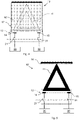
- Figs. 2 and 3 illustrate the warning sign arrangement 10 according to the first example embodiment in greater detail, wherein fig. 2 shows the warning sign arrangement 10 in an unexposed state, i.e. with a warning sign hidden, and fig. 3 shows the warning sign arrangement 10 in an exposed state, i.e. with a triangular warning sign 11 exposed.
- the warning sign arrangement 10 comprises a warning sign hiding device 12 comprising an electric locking mechanism 13.
- the electric locking mechanism 13 in turn comprises a first electric lock 14 configured to be powered by a main electric power supply 20 of the vehicle 1, and a second electric lock 15 configured to be powered by a backup electric power supply 30 of the vehicle 1, as described above.
- the warning sign hiding device 12 is configured to hide the warning sign 11 in the unexposed state, when the electric locking mechanism 13 is active as illustrated in fig. 2 .
- the warning sign hiding device 12 is further configured to expose the warning sign 11 in the exposed state, when the electric locking mechanism 13 is deactivated, as illustrated in fig. 3 . Both of the first electric lock 14 and the second electric lock 15 must be deactivated to expose the warning sign 11.
- the warning sign hiding device 12 comprises a foldable covering device 16 configured to hide the warning sign 11 when the electric locking mechanism 13 is active, i.e. when electric power is supplied to both electric locks 14, 15 from the main electric power supply 20 and from the backup electric power supply 30, respectively.
- the foldable covering device 16 comprises an upper segment 17a, a lower segment 17b, and a hinge mechanism 18 provided between the segments 17a, 17b, so that the two segments 17a, 17b are foldable onto one another.
- An upper part of the warning sign 11, dashed in fig. 2 is provided on a surface of the upper segment 17a, while a lower part of the warning sign 11, shown with contours only in fig. 2 , is provided on a surface of the lower segment 17b.
- the electric locks 14, 15 are positioned vertically above the warning sign 11.
- the electric locks 14, 15 are active, i.e. when electric power is supplied to the electric locks 14, 15, the lower segment 17b is folded onto the upper segment 17a so that the surfaces on which the warning sign 11 is provided are folded toward one another and the warning sign 11 is consequently hidden.
- gravity causes the lower segment 17b to fall down and expose the warning sign 11.
- the upper segment 17a may be omitted, with the upper part of the warning sign 11 painted directly on the rear end surface 2 of the vehicle 1 and the lower part provided on a covering device hinged to the rear end surface 2 of the vehicle 1.
- the electric locking mechanism may be provided vertically above the covering device so that the covering device, when the electric locking mechanism is active, hides the upper part of the warning sign in the same way as illustrated in fig. 2 .
- more than two segments 17a, 17b may be provided, such as a plurality of vertically stackable segments foldable onto one another.
- a warning sign arrangement 10' according to a second example embodiment is shown in figs. 4-5.
- Fig. 4 shows the warning sign arrangement 10' in the unexposed state, with a warning sign 11 indicated using dashed lines
- fig. 5 shows the warning sign arrangement 10' in the exposed state.
- the locking mechanism 13 comprising the first and second electric locks 14, 15 is provided vertically below a rollable covering device 16' and below the warning sign 11.
- a spring member (not shown) is arranged to roll up the rollable covering device 16', similar to a roller blind, upon deactivation of both the electric locks 14, 15, such as upon interruption of the power supply from the main electric power supply 20 and the backup electric power supply 30, respectively.
- the electric locks 14, 15 hold the rollable covering device 16' unrolled against the force of the spring member when active.
- the force of the spring member rolls up the covering device 16' and the warning sign 11 is exposed.
- the covering device 16' is thus located above the warning sign 11.
- the electric locking mechanism may be provided above the warning sign or beside the warning sign, with a roller of the rollable covering device located at the opposite side of the warning side with respect to the electric locking mechanism.
- the first electric lock 14 is configured to be deactivated automatically in response to an interruption of the main electric power supply 20
- the second electric lock 15 is configured to be deactivated automatically in response to an interruption of the backup electric power supply 30.
- Such an interruption may be caused by a power-down of the vehicle 1.
- the electric locking mechanism 13 may also be configured to be deactivatable in response to receiving a deactivation signal. In response to receiving the deactivation signal, switches 21, 31 are opened so as to interrupt the power supply to both of the electric locks 14, 15.
- the electric locking mechanism 13 may for this purpose comprise a control unit (not shown) provided with a communication interface for receiving signals via a hard-wired or wireless network. If only one of the main electric power supply 20 and the backup power supply 30 is functional, the electric locking mechanism 13 may upon receipt of the signal open the switch that turns off the power supply to the still active one of the two electric locks 14, 15, while the other electric lock has already been deactivated as a result of the malfunctioning power supply.
- the first and the second electric locks 14, 15 may be any kind of locks that need electric power to be in a closed, active state, and that will transition to an open, deactivated state when no electric power is supplied to the electric lock.
- Such electric locks may be referred to as fail-safe electric locks, i.e. locks that are unlocked when de-energized.
- the electric locks 14, 15 may be electromagnetic locks or fail-safe electric solenoid locks.
Landscapes
- Engineering & Computer Science (AREA)
- Mechanical Engineering (AREA)
- Architecture (AREA)
- Civil Engineering (AREA)
- Structural Engineering (AREA)
- Emergency Alarm Devices (AREA)
- Lighting Device Outwards From Vehicle And Optical Signal (AREA)
Priority Applications (3)
| Application Number | Priority Date | Filing Date | Title |
|---|---|---|---|
| EP21172719.3A EP4086115A1 (de) | 2021-05-07 | 2021-05-07 | Warnschildanordnung für ein fahrzeug |
| US17/660,921 US12459426B2 (en) | 2021-05-07 | 2022-04-27 | Warning sign arrangement for a vehicle |
| CN202210479376.XA CN115303177A (zh) | 2021-05-07 | 2022-05-05 | 用于车辆的警示标志装置 |
Applications Claiming Priority (1)
| Application Number | Priority Date | Filing Date | Title |
|---|---|---|---|
| EP21172719.3A EP4086115A1 (de) | 2021-05-07 | 2021-05-07 | Warnschildanordnung für ein fahrzeug |
Publications (1)
| Publication Number | Publication Date |
|---|---|
| EP4086115A1 true EP4086115A1 (de) | 2022-11-09 |
Family
ID=75870455
Family Applications (1)
| Application Number | Title | Priority Date | Filing Date |
|---|---|---|---|
| EP21172719.3A Pending EP4086115A1 (de) | 2021-05-07 | 2021-05-07 | Warnschildanordnung für ein fahrzeug |
Country Status (3)
| Country | Link |
|---|---|
| US (1) | US12459426B2 (de) |
| EP (1) | EP4086115A1 (de) |
| CN (1) | CN115303177A (de) |
Citations (7)
| Publication number | Priority date | Publication date | Assignee | Title |
|---|---|---|---|---|
| CN201283828Y (zh) * | 2008-08-14 | 2009-08-05 | 陈冠均 | 一种车用自走式安全告示系统及其告示装置 |
| KR20130090439A (ko) * | 2012-02-04 | 2013-08-14 | 박동철 | 차량용 교통안전표지 주름식 표시장치 |
| DE102016014025A1 (de) | 2016-11-24 | 2017-08-17 | Daimler Ag | Warnvorrichtung zum automatischen Aufstellen eines Warnsignalelements, insbesondere Warndreiecks |
| KR20180098835A (ko) * | 2017-02-27 | 2018-09-05 | 백남찬 | 차량 트렁크 설치형 삼각대 |
| CN110525331A (zh) * | 2019-09-29 | 2019-12-03 | 西安图唯谷创新科技有限公司 | 一种汽车故障警示装置 |
| CN112248930A (zh) * | 2020-10-22 | 2021-01-22 | 广西科技大学 | 一种智能汽车警示装置 |
| WO2021083484A1 (en) * | 2019-10-28 | 2021-05-06 | Volvo Truck Corporation | Road user warning arrangement |
Family Cites Families (63)
| Publication number | Priority date | Publication date | Assignee | Title |
|---|---|---|---|---|
| US3255725A (en) * | 1964-07-23 | 1966-06-14 | Kreidner Ernest R Von | Safety signal for automotive vehicles |
| US3800430A (en) * | 1970-06-04 | 1974-04-02 | Samra Herb | Multiple purpose vehicle signal device |
| US4054789A (en) * | 1976-03-30 | 1977-10-18 | Frances Romanelli | Vehicle safety light |
| US4129857A (en) * | 1977-05-26 | 1978-12-12 | Espinosa A | Portable driver emergency device |
| US4192090A (en) * | 1977-06-07 | 1980-03-11 | Marion Seth | Vehicle safety light |
| US4456126A (en) * | 1983-02-04 | 1984-06-26 | Hicks Jr James D | Safety kit |
| US4787163A (en) * | 1986-06-16 | 1988-11-29 | Berg Marlin C | Vehicle mounted sign |
| US5097612A (en) * | 1990-09-26 | 1992-03-24 | Syntonic Technology, Inc. | Illuminated traffic control sign |
| US5566485A (en) * | 1995-11-24 | 1996-10-22 | Chang; Shin-Shui | Car-used distress sign |
| JPH1089217A (ja) * | 1996-09-17 | 1998-04-07 | Honda Motor Co Ltd | 車両用盗難防止装置 |
| US5764141A (en) * | 1997-02-06 | 1998-06-09 | Chang; Jih-Cheng | Motor vehicle warning signal light assembly |
| US5970639A (en) * | 1998-06-04 | 1999-10-26 | Hui; Liao Chih | Innovated type of hazard alarm sign |
| TW497630U (en) * | 1999-10-14 | 2002-08-01 | Rung-Fang Dung | Gleaming alarm device used in triangle alarm symbol of car malfunction |
| US6799877B2 (en) * | 2002-12-13 | 2004-10-05 | Don't Die, Llc | Emergency light signal |
| US20050018444A1 (en) * | 2003-07-23 | 2005-01-27 | Todd Larry R. | Illuminated hazard warning light |
| US6946955B2 (en) * | 2004-01-21 | 2005-09-20 | Golder Thomas J | Initial movement indicator system and method for a wheeled ground vehicle |
| US7096102B1 (en) * | 2004-02-27 | 2006-08-22 | Parker Sr Harold C | Motor vehicle license plate with integral wireless tracking and data dissemination device |
| US7142103B2 (en) * | 2004-11-02 | 2006-11-28 | Chang-Hao Chen | Mobile signal light set |
| US7258506B2 (en) * | 2004-12-10 | 2007-08-21 | John M. Tipaldo | Triangular retractable safety marker |
| JP2007137299A (ja) * | 2005-11-21 | 2007-06-07 | Toyota Motor Corp | 電源供給制御装置 |
| JP4367504B2 (ja) * | 2007-03-06 | 2009-11-18 | 株式会社デンソー | 車載緊急通報装置 |
| US20090109023A1 (en) * | 2007-10-31 | 2009-04-30 | Shawn Newman | Apparatus and method for locating a motor vehicle by visible indication |
| CN100569558C (zh) * | 2008-05-07 | 2009-12-16 | 李政文 | 电动隐藏式车用醒目警示牌 |
| EP2379286B1 (de) * | 2008-12-17 | 2013-03-27 | ABB Research Ltd. | System zur verhinderung von schäden für einen manipulator |
| US8487752B2 (en) * | 2011-03-23 | 2013-07-16 | Chrysler Group Llc | External status indicator for an electric vehicle |
| US9171439B2 (en) * | 2011-07-06 | 2015-10-27 | Checkpoint Systems, Inc. | Method and apparatus for powering a security device |
| KR102073999B1 (ko) * | 2011-07-17 | 2020-02-05 | 에스이에스 솔루션스 게엠베하 | 루프박스, 루프박스를 장착한 차량루프와 루프박스를 내장한 자동차 |
| TWI453432B (zh) * | 2012-11-28 | 2014-09-21 | Simplo Technology Co Ltd | 絕緣偵測電路及其方法 |
| KR101743233B1 (ko) * | 2013-01-30 | 2017-06-05 | 주식회사 케이티 | 전기차의 배터리 잔량 정보 제공 시스템 및 이를 이용한 전기차의 배터리 잔량 정보 제공 방법 |
| JP6079705B2 (ja) * | 2014-06-23 | 2017-02-15 | トヨタ自動車株式会社 | 車両用緊急通報装置 |
| US9518408B1 (en) * | 2015-05-21 | 2016-12-13 | Ford Global Technologies, Llc | Alternate backup entry for vehicles |
| US10124757B1 (en) * | 2015-07-23 | 2018-11-13 | Traffic Safety Specialists Inc. | Vehicle collision avoidance system |
| US10876329B2 (en) * | 2015-10-16 | 2020-12-29 | Magna Closures S.P.A. | Electrical door latch |
| US9840193B1 (en) * | 2016-07-15 | 2017-12-12 | Ford Global Technologies, Llc | Vehicle lighting assembly |
| BR112019011380A2 (pt) * | 2016-12-06 | 2019-10-15 | Nissan North America Inc | geração de dados de solução para veículos autônomos para negociar situações de problema |
| US10261513B2 (en) * | 2016-12-19 | 2019-04-16 | drive.ai Inc. | Methods for communicating state, intent, and context of an autonomous vehicle |
| JP6801528B2 (ja) * | 2017-03-08 | 2020-12-16 | 株式会社オートネットワーク技術研究所 | 車載用電源部の制御装置及び車載用電源装置 |
| US11065979B1 (en) * | 2017-04-05 | 2021-07-20 | H55 Sa | Aircraft monitoring system and method for electric or hybrid aircrafts |
| US10102782B1 (en) * | 2017-04-25 | 2018-10-16 | Roman Konshin | Road side vehicle distress sign |
| US20190031094A1 (en) * | 2017-07-25 | 2019-01-31 | Ford Global Technologies, Llc | System and method of illuminating a cargo area of a motor vehicle |
| DE102017221199B4 (de) * | 2017-11-27 | 2023-02-09 | Audi Ag | Betätigungseinrichtung zum Betätigen einer Getriebenotentriegelung eines Getriebes eines Kraftfahrzeugs, insbesondere eines Kraftwagens |
| DE102017222192A1 (de) * | 2017-12-07 | 2019-06-13 | Audi Ag | HV-Batterieanordnung für ein Kraftfahrzeug, Bordnetz, Kraftfahrzeug und Verfahren zum Steuern einer HV-Batterieanordnung |
| WO2019139221A1 (ko) * | 2018-01-09 | 2019-07-18 | 박세헌 | 차량용 경고표시장치 |
| KR102532312B1 (ko) * | 2018-03-06 | 2023-05-16 | 현대자동차주식회사 | 차량의 전원 공급 시스템 및 이를 제어하는 방법 |
| JP6757366B2 (ja) * | 2018-06-26 | 2020-09-16 | 株式会社Subaru | 車両用電源装置 |
| JP6706288B2 (ja) * | 2018-06-26 | 2020-06-03 | 株式会社Subaru | 車両用電源装置 |
| US20200017024A1 (en) * | 2018-07-13 | 2020-01-16 | Ida Mollo | Magnetic led warning arrow sign |
| JP7003863B2 (ja) * | 2018-07-20 | 2022-02-04 | トヨタ自動車株式会社 | 車両の制御装置、制御方法および制御プログラム |
| KR102478121B1 (ko) * | 2018-08-23 | 2022-12-15 | 현대자동차주식회사 | 차량용 전자 제어장치의 전력 제어 시스템 및 방법 |
| KR102467843B1 (ko) * | 2018-08-23 | 2022-11-16 | 삼성전자주식회사 | 보조 전원 장치의 모니터링 방법과 장치, 및 그 장치를 포함한 전자 시스템 |
| US10793107B2 (en) * | 2018-08-30 | 2020-10-06 | Ford Global Technologies, Llc | Vehicle door activation device |
| JP7024667B2 (ja) * | 2018-08-30 | 2022-02-24 | トヨタ自動車株式会社 | 車両用電源システム |
| EP3623226B1 (de) * | 2018-09-17 | 2025-08-13 | KNORR-BREMSE Systeme für Nutzfahrzeuge GmbH | Zusätzliche stromversorgung und verfahren zur bereitstellung von zusätzlichem strom |
| JP7017138B2 (ja) * | 2018-12-03 | 2022-02-08 | 株式会社オートネットワーク技術研究所 | 車載用のバックアップ電源制御装置、及び車載用のバックアップ電源 |
| JP7191750B2 (ja) * | 2019-03-26 | 2022-12-19 | 株式会社デンソーテン | 電源制御装置 |
| GB2585376B (en) * | 2019-07-04 | 2021-09-15 | Ipft Fuels Ltd | Apparatus for transferring electrical power to or from an electric vehicle, and control method thereof |
| KR20210026250A (ko) * | 2019-08-29 | 2021-03-10 | 현대자동차주식회사 | 영상기록시스템의 전원 제어 장치 및 그 방법 |
| JP7226356B2 (ja) * | 2020-02-03 | 2023-02-21 | トヨタ自動車株式会社 | 車両用制御装置、方法、プログラム、及び車両 |
| JP7354931B2 (ja) * | 2020-06-02 | 2023-10-03 | トヨタ自動車株式会社 | 車両販売システム |
| KR102821240B1 (ko) * | 2020-07-06 | 2025-06-18 | 현대자동차주식회사 | 차량 및 그 제어 방법 |
| KR102880900B1 (ko) * | 2020-09-03 | 2025-11-03 | 현대자동차주식회사 | 차량의 경고메시지 전달 장치 |
| US11702020B2 (en) * | 2021-02-25 | 2023-07-18 | Tusimple, Inc. | Redundant power bridge battery architecture |
| US11851002B2 (en) * | 2021-08-05 | 2023-12-26 | Atieva, Inc. | Sensor-friendly vehicle warning sign |
-
2021
- 2021-05-07 EP EP21172719.3A patent/EP4086115A1/de active Pending
-
2022
- 2022-04-27 US US17/660,921 patent/US12459426B2/en active Active
- 2022-05-05 CN CN202210479376.XA patent/CN115303177A/zh active Pending
Patent Citations (7)
| Publication number | Priority date | Publication date | Assignee | Title |
|---|---|---|---|---|
| CN201283828Y (zh) * | 2008-08-14 | 2009-08-05 | 陈冠均 | 一种车用自走式安全告示系统及其告示装置 |
| KR20130090439A (ko) * | 2012-02-04 | 2013-08-14 | 박동철 | 차량용 교통안전표지 주름식 표시장치 |
| DE102016014025A1 (de) | 2016-11-24 | 2017-08-17 | Daimler Ag | Warnvorrichtung zum automatischen Aufstellen eines Warnsignalelements, insbesondere Warndreiecks |
| KR20180098835A (ko) * | 2017-02-27 | 2018-09-05 | 백남찬 | 차량 트렁크 설치형 삼각대 |
| CN110525331A (zh) * | 2019-09-29 | 2019-12-03 | 西安图唯谷创新科技有限公司 | 一种汽车故障警示装置 |
| WO2021083484A1 (en) * | 2019-10-28 | 2021-05-06 | Volvo Truck Corporation | Road user warning arrangement |
| CN112248930A (zh) * | 2020-10-22 | 2021-01-22 | 广西科技大学 | 一种智能汽车警示装置 |
Also Published As
| Publication number | Publication date |
|---|---|
| CN115303177A (zh) | 2022-11-08 |
| US20220355729A1 (en) | 2022-11-10 |
| US12459426B2 (en) | 2025-11-04 |
Similar Documents
| Publication | Publication Date | Title |
|---|---|---|
| US12077194B2 (en) | Vehicle | |
| US12459533B2 (en) | Vehicle with mountable and removable autonomous driving system | |
| US6322161B1 (en) | Apparatus and methods for automatic engagement and locking of vehicle air parking brake | |
| US20230347879A1 (en) | Autonomous driving system for communicating with and controlling a vehicle via a vehicle control interface | |
| US5128651A (en) | School bus alarm system | |
| US11813995B2 (en) | Redundant power distribution system based on single power source | |
| WO2020029791A1 (zh) | 轨道车辆紧急制动安全环线电路及轨道车辆 | |
| US12459426B2 (en) | Warning sign arrangement for a vehicle | |
| JP2014177202A (ja) | 鉄道車両用空力ブレーキ装置 | |
| US20060244309A1 (en) | Vehicle power and communication bus and system | |
| CN112780146B (zh) | 一种列车车门控制系统及控制方法 | |
| US20250219402A1 (en) | Redundant power distribution system based on single power source | |
| JP7815073B2 (ja) | 車両電源システム | |
| JPH0667187U (ja) | 扉連動ステップの制御装置 | |
| US20250346124A1 (en) | Zonal architecture circuit design | |
| CN208016135U (zh) | 工程运输车的车身控制器 | |
| CN215622248U (zh) | 一种车辆的转向控制装置 | |
| KR20170013446A (ko) | 이중전원공급라인을 갖는 고속차량 주간제어기 시스템 | |
| US20230001886A1 (en) | Method and system for preventing the driving of an electrically driven vehicle | |
| SE542850C2 (en) | A safety method, a control device, a vehicle, a computer program and a computer-readable medium. | |
| NL1041473B1 (en) | Emergency safety drive for vehicles. | |
| CN119459629A (zh) | 冗余制动系统、车辆制动系统及车辆 | |
| US20230406199A1 (en) | Safety System For An Autonomous Vehicle, And Method For Operating A Safety System Of An Autonomous Vehicle | |
| JPH08223793A (ja) | 車両の電源切換装置 | |
| DE102025116839A1 (de) | Multizonale fahrzeugarchitektur |
Legal Events
| Date | Code | Title | Description |
|---|---|---|---|
| PUAI | Public reference made under article 153(3) epc to a published international application that has entered the european phase |
Free format text: ORIGINAL CODE: 0009012 |
|
| STAA | Information on the status of an ep patent application or granted ep patent |
Free format text: STATUS: THE APPLICATION HAS BEEN PUBLISHED |
|
| AK | Designated contracting states |
Kind code of ref document: A1 Designated state(s): AL AT BE BG CH CY CZ DE DK EE ES FI FR GB GR HR HU IE IS IT LI LT LU LV MC MK MT NL NO PL PT RO RS SE SI SK SM TR |
|
| STAA | Information on the status of an ep patent application or granted ep patent |
Free format text: STATUS: REQUEST FOR EXAMINATION WAS MADE |
|
| 17P | Request for examination filed |
Effective date: 20230331 |
|
| RBV | Designated contracting states (corrected) |
Designated state(s): AL AT BE BG CH CY CZ DE DK EE ES FI FR GB GR HR HU IE IS IT LI LT LU LV MC MK MT NL NO PL PT RO RS SE SI SK SM TR |
|
| STAA | Information on the status of an ep patent application or granted ep patent |
Free format text: STATUS: EXAMINATION IS IN PROGRESS |
|
| 17Q | First examination report despatched |
Effective date: 20250818 |