EP4086127A1 - Actionneur de frein à ressort - Google Patents
Actionneur de frein à ressort Download PDFInfo
- Publication number
- EP4086127A1 EP4086127A1 EP21172409.1A EP21172409A EP4086127A1 EP 4086127 A1 EP4086127 A1 EP 4086127A1 EP 21172409 A EP21172409 A EP 21172409A EP 4086127 A1 EP4086127 A1 EP 4086127A1
- Authority
- EP
- European Patent Office
- Prior art keywords
- housing
- brake actuator
- section
- spring
- inlet port
- Prior art date
- Legal status (The legal status is an assumption and is not a legal conclusion. Google has not performed a legal analysis and makes no representation as to the accuracy of the status listed.)
- Pending
Links
Images
Classifications
-
- F—MECHANICAL ENGINEERING; LIGHTING; HEATING; WEAPONS; BLASTING
- F16—ENGINEERING ELEMENTS AND UNITS; GENERAL MEASURES FOR PRODUCING AND MAINTAINING EFFECTIVE FUNCTIONING OF MACHINES OR INSTALLATIONS; THERMAL INSULATION IN GENERAL
- F16D—COUPLINGS FOR TRANSMITTING ROTATION; CLUTCHES; BRAKES
- F16D65/00—Parts or details
- F16D65/14—Actuating mechanisms for brakes; Means for initiating operation at a predetermined position
-
- B—PERFORMING OPERATIONS; TRANSPORTING
- B60—VEHICLES IN GENERAL
- B60T—VEHICLE BRAKE CONTROL SYSTEMS OR PARTS THEREOF; BRAKE CONTROL SYSTEMS OR PARTS THEREOF, IN GENERAL; ARRANGEMENT OF BRAKING ELEMENTS ON VEHICLES IN GENERAL; PORTABLE DEVICES FOR PREVENTING UNWANTED MOVEMENT OF VEHICLES; VEHICLE MODIFICATIONS TO FACILITATE COOLING OF BRAKES
- B60T17/00—Component parts, details, or accessories of power brake systems not covered by groups B60T8/00, B60T13/00 or B60T15/00, or presenting other characteristic features
- B60T17/08—Brake cylinders other than ultimate actuators
- B60T17/088—Mounting arrangements
-
- B—PERFORMING OPERATIONS; TRANSPORTING
- B60—VEHICLES IN GENERAL
- B60T—VEHICLE BRAKE CONTROL SYSTEMS OR PARTS THEREOF; BRAKE CONTROL SYSTEMS OR PARTS THEREOF, IN GENERAL; ARRANGEMENT OF BRAKING ELEMENTS ON VEHICLES IN GENERAL; PORTABLE DEVICES FOR PREVENTING UNWANTED MOVEMENT OF VEHICLES; VEHICLE MODIFICATIONS TO FACILITATE COOLING OF BRAKES
- B60T13/00—Transmitting braking action from initiating means to ultimate brake actuator with power assistance or drive; Brake systems incorporating such transmitting means, e.g. air-pressure brake systems
- B60T13/10—Transmitting braking action from initiating means to ultimate brake actuator with power assistance or drive; Brake systems incorporating such transmitting means, e.g. air-pressure brake systems with fluid assistance, drive, or release
- B60T13/24—Transmitting braking action from initiating means to ultimate brake actuator with power assistance or drive; Brake systems incorporating such transmitting means, e.g. air-pressure brake systems with fluid assistance, drive, or release the fluid being gaseous
- B60T13/26—Compressed-air systems
- B60T13/38—Brakes applied by springs or weights and released by compressed air
-
- B—PERFORMING OPERATIONS; TRANSPORTING
- B60—VEHICLES IN GENERAL
- B60T—VEHICLE BRAKE CONTROL SYSTEMS OR PARTS THEREOF; BRAKE CONTROL SYSTEMS OR PARTS THEREOF, IN GENERAL; ARRANGEMENT OF BRAKING ELEMENTS ON VEHICLES IN GENERAL; PORTABLE DEVICES FOR PREVENTING UNWANTED MOVEMENT OF VEHICLES; VEHICLE MODIFICATIONS TO FACILITATE COOLING OF BRAKES
- B60T17/00—Component parts, details, or accessories of power brake systems not covered by groups B60T8/00, B60T13/00 or B60T15/00, or presenting other characteristic features
- B60T17/08—Brake cylinders other than ultimate actuators
- B60T17/085—Spring loaded brake actuators
-
- F—MECHANICAL ENGINEERING; LIGHTING; HEATING; WEAPONS; BLASTING
- F16—ENGINEERING ELEMENTS AND UNITS; GENERAL MEASURES FOR PRODUCING AND MAINTAINING EFFECTIVE FUNCTIONING OF MACHINES OR INSTALLATIONS; THERMAL INSULATION IN GENERAL
- F16D—COUPLINGS FOR TRANSMITTING ROTATION; CLUTCHES; BRAKES
- F16D65/00—Parts or details
- F16D65/14—Actuating mechanisms for brakes; Means for initiating operation at a predetermined position
- F16D65/16—Actuating mechanisms for brakes; Means for initiating operation at a predetermined position arranged in or on the brake
-
- F—MECHANICAL ENGINEERING; LIGHTING; HEATING; WEAPONS; BLASTING
- F16—ENGINEERING ELEMENTS AND UNITS; GENERAL MEASURES FOR PRODUCING AND MAINTAINING EFFECTIVE FUNCTIONING OF MACHINES OR INSTALLATIONS; THERMAL INSULATION IN GENERAL
- F16D—COUPLINGS FOR TRANSMITTING ROTATION; CLUTCHES; BRAKES
- F16D65/00—Parts or details
- F16D65/14—Actuating mechanisms for brakes; Means for initiating operation at a predetermined position
- F16D65/28—Actuating mechanisms for brakes; Means for initiating operation at a predetermined position arranged apart from the brake
-
- F—MECHANICAL ENGINEERING; LIGHTING; HEATING; WEAPONS; BLASTING
- F16—ENGINEERING ELEMENTS AND UNITS; GENERAL MEASURES FOR PRODUCING AND MAINTAINING EFFECTIVE FUNCTIONING OF MACHINES OR INSTALLATIONS; THERMAL INSULATION IN GENERAL
- F16D—COUPLINGS FOR TRANSMITTING ROTATION; CLUTCHES; BRAKES
- F16D2121/00—Type of actuator operation force
- F16D2121/02—Fluid pressure
- F16D2121/04—Fluid pressure acting on a piston-type actuator, e.g. for liquid pressure
-
- F—MECHANICAL ENGINEERING; LIGHTING; HEATING; WEAPONS; BLASTING
- F16—ENGINEERING ELEMENTS AND UNITS; GENERAL MEASURES FOR PRODUCING AND MAINTAINING EFFECTIVE FUNCTIONING OF MACHINES OR INSTALLATIONS; THERMAL INSULATION IN GENERAL
- F16D—COUPLINGS FOR TRANSMITTING ROTATION; CLUTCHES; BRAKES
- F16D2125/00—Components of actuators
- F16D2125/02—Fluid-pressure mechanisms
Definitions
- the present invention relates to a spring brake actuator, preferably for use in a commercial vehicle, according to a spring brake actuator, preferably for use in a commercial vehicle, said actuator comprising:
- Spring brake actuators of the aforementioned kind are used in the commercial vehicle industry to provide a service brake, a parking and/or emergency brake capability.
- Spring brake actuators are regularly connected to a service brake actuator and often act upon the same brake components which transmit the brake force to the vehicle wheel. Utilizing these two brake types together requires to ensure that only one of the brakes is activated at a time.
- a service brake and a parking or emergency brake are combined, each brake part having a housing including a spring brake chamber.
- the two housings are connected by means of a bayonet connection.
- the first housing may include the service brake actuators
- the second housing includes the parking brake actuator.
- the bayonet connection is typically realized by bayonet notches positioned at an end section of a first housing (e.g. for the service brake actuator), and corresponding bayonet recesses are positioned on an opposing end section of the second housing (e.g. for a parking brake actuator) or vice versa.
- the spring brake chambers using bayonet connections require a certain length in the longitudinal direction of the housing, and they are limited for total length reduction of the complete device.
- the total length of the brake actuator is critical, because the overall space available for the brake actuator is typically limited within the vehicle, in particular commercial vehicles.
- One reason for the limitation for the total length reduction is that a central component connecting the service part housing and the parking part housing, which central component is often referred to as flange, requires a certain length in the axial (or longitudinal) direction of the housing or piston, because this central component must contain the inlet ports for supplying pressurized air into the housing and chambers.
- the inlet port sections and the bayonet connection elements are arranged after one another in the longitudinal direction of the housing, which typically coincides with the longitudinal axis of the piston and piston rod connected to the piston. This required space for the inlet ports as well as the mechanical connection elements limits the desired length reduction of the complete actuator.
- the invention attains this object by providing a spring brake actuator according to claim 1 which is in particular characterized in that the gas inlet port(s) and the mechanical connection section are positioned along the circumference of the housing within the same gas inlet port section of the housing extending into the direction of the longitudinal axis.
- the mechanical connection section and the gas inlet ports or gas inlet port area are positioned in the same area for the gas inlet port(s) with respect to the longitudinal axis of the housing, brake piston and thus the spring brake actuator. Both functionalities are maintained, but the required space in the longitudinal direction is reduced, so that the overall required space or length can be reduced.
- the mechanical connection section and the inlet ports are positioned in the same area or section of the housing which is often referred to as flange, the overall length can be reduced.
- the gas inlet port(s) and the mechanical connection elements are essentially positioned along a circumferential circular line or band along the housing, wherein the longitudinal axis of the housing coincides with the center of the circumferential circular line or band.
- both the gas inlet ports and the mechanical connection means are within the same area along the periphery of the housing, this area extending only in a relatively short dimension in the direction of the longitudinal axis of the housing. This, in safes space in the longitudinal direction and results in a reduced overall length of the break actuator.
- the axial dimension of this section of the housing in accordance with the invention depends on the dimension of the actuator, but can be kept small. For example, this axial dimension can have approximately the size of the diameter of the inlet ports or slightly larger, for example about the factor 1,25 of the diameter of the inlet port.
- the mechanical connection section includes a bayonet connection having a plurality of bayonet connection elements and that the gas inlet port(s) is positioned between bayonet connection elements.
- the actual length of the mechanical connection section can be kept small when the gas inlet port is positioned between those bayonet connection elements.
- the bayonet connection elements are bayonet notches and that the gas inlet port(s) are positioned between notches.
- the housing comprises cylindrical holes or recesses forming the inlet ports, and that the bayonet connection elements are positioned between these holes or recesses.
- a port connector for introducing pressurized gas is connected with an inlet port formed within the housing and protrudes radially from the housing.
- the port connector preferably extends through the recess of the housing of the adjacent housing and can easily be connected to the further pressurized gas line.
- the port connector in the mounted position, extends through a recess or hole formed in the second housing and is attached in fluid communication with an inlet port communicating with the brake piston, so that the first housing and second housing cannot be rotated with respect to each other along the longitudinal axis so that the bayonet connection is blocked.
- the port connector thus has a double function: for allowing a good connection to the pressurized gas source, and also blocking the bayonet connection, so that the two housings are coupled reliably to each other. Also, and incorrect assembly can be avoided. It can be prevented that the bayonet connection is connected in a wrong position, also, it can be avoided that the two housings are disconnected by accident or inadvertently.
- the port connector has an outer thread and is screwed into the inlet port having an inner thread.
- the inlet port(s) are formed on a protruding portion of the first housing extending radially outwardly, and that the bayonet elements are positioned between those protruding housing sections.
- the protruding portion of the first housing has a section referred to as flange, and can be integrated into that housing section.
- the bayonet elements on the first housing are formed as notches and the bayonet elements on the second housing are formed as depressions extending essentially into the circumferential direction with respect to the longitudinal axis.
- the first housing is connected with a second housing for a second brake actuator by means of the bayonet connection elements, and that the bayonet connection elements are notches formed in the first housing and/or the second housing and recesses formed in the second housing and/or first housing.
- a preferred embodiment is characterized in that the second housing comprises an essentially cylindrical shape, and the recesses of the bayonet section are formed in a cylindrical end section having a larger diameter than the adjacent section of the second housing.
- the two housings can be coupled easily in this way.
- the first housing includes elements of a service brake including at least a spring
- the second housing includes elements of a park brake including a brake piston, a spring and/or a release bolt.
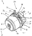
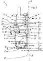
- Fig. 1 shows a perspective view and Fig 3 a cross-sectional schematic view of a spring brake actuator 2.
- the spring brake actuator 2 comprises a cylindrical or cylinder (first) housing 4, preferably of a parking brake section 11 of the brake actuator 2.
- the housing 4 for the brake actuator has an interior space for receiving components of the brake actuator 2, Inside the housing 4, as shown in Fig. 3 , a compression spring 8 and a pressure chamber 5 are arranged.
- the pressure chamber 5 defines the parking stroke area 7 of the parking brake section in the shown embodiment.
- the compression spring 8 is positioned within a parking spring area 9 and rests on the lower side of Fig. 1 or Fig. 3 against a cylinder housing base 6 and on the opposite side on a spring brake piston 10.
- the spring brake piston 10 is in Fig.
- the brake piston 10 has a longitudinal axis A.
- the housing 4 also has a longitudinal axis A which coincides with - or is parallel to - the longitudinal axis A of the piston 10.
- the spring brake piston 10 is adapted to act upon a diaphragm 24 of the spring brake actuator 2 which transmits the inflicted force to a rod 26 which, in turn, transmits the applied power to the wheel brakes (not shown).
- the spring brake actuator 2 furthermore comprises a release bolt 29.
- the release bolt 29 is utilized to release the spring brake actuator 2 in case of mal-functions, for example.
- the spring brake actuator 2 moreover comprises a service brake 27 (or service brake section), as shown in Fig. 1 and Fig. 3 .
- a flange portion 18 is utilized to connect the service brake 27.
- the service brake 27 has a housing 31, which is the second housing with respect to the first housing 4 in the lower section of the spring brake actuator 2.
- the service brake 27 comprises a service brake pressure chamber 25 ( Fig. 3 ), into which a pressure may be built up to generate a force upon the service diaphragm 28 which transmits the inflicted force to the rod 26.
- the first housing 4 thus includes elements of a service brake 27 including at least a service brake spring 30, and the second housing includes elements of a park brake including a brake piston, a spring and/or a release bolt
- the first housing 4 and the second housing 31 form the combined housing of the shown spring brake actuator 2.
- a mechanical connection section 33 is designed and adapted to connect housing 4 and housing 31 mechanically.
- the mechanical connection section 33 .
- gas inlet ports 32, 34 for introducing pressurized gas, in particular pressurized air into the housing 4, 31 to actuate the brake actuator 2, in particular the parking brake section 11 and the service brake 27 of the actuator 2, are provided in the area of the mechanical connection section 33. This area thus also forms a gas inlet port section 35 of the housing.
- the gas inlet port(s) 32, 34 and the mechanical connection section 33 are positioned along the circumference of the housing 4, 31 within the gas inlet port section 35 of the housing extending into the direction of the longitudinal axis (A).
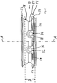
- both the gas inlet ports 32, 34, of the gas inlet port section 35 as well as the mechanical connection section 33 are positioned at the same area, only a relatively small section or length B illustrated in Fig. 2 and Fig. 3 into the axial direction along the longitudinal axis A is required in accordance with the preferred embodiment, so that the overall axial length of the brake actuator 2 is relatively small and smaller compared to the known brake actuators.
- the length B can be kept short, because both the mechanical connection section 33 as well as the gas inlet port section 35 are positioned in the same area. They both extend also along the circumference of the housing.
- gas inlet ports 32, 34 for supplying pressurized gas into the housing 4, 31 and for applying pressure to the brake piston(s) 10 are associated with the housing 4, 31.
- each gas inlet port 32, 34 comprises a port connector 36, 38 for introducing pressurized gas into the inlet port 32, 34 formed within the housing 4, 31 and protrudes radially from the housing 4, 31 with respect to the longitudinal axis A.
- a pressurized gas line (not shown) can be connected with the port connector 34, 38.
- each port connector 36, 38 has an outer thread 40, 42 and is screwed into the inlet port 32, 34 having an inner thread (not shown).
- recess 44, 46 has an U-shaped edge.
- recesses 44, 46 can have different shapes such as a circular or rectangular hole or other shapes.
- the inlet port(s) 32, 34 and/or recesses 44, 46 are positioned or formed on a protruding portion 48 of the first housing 4 extending radially outwardly and having a larger a diameter than the lower portion of the cylindrical housing 4.
- connection section 33 comprises connection part 50 for connecting the housing 31 of the service brake 27 and housing 4 of the parking brake section 11.
- Connection part 50 may for example be a casted or deep drawn workpiece. It comprises the flange portion 18 with a radially outwardly protrusion 52 which mechanically interacts with a lower protruding section 54 of the housing 31 having a C-shaped cross-section, so that the housing 31 can be connected with the connection part 50 by means of a form fit connection.
- a plurality of mechanical connection elements preferably bayonet elements in the form of projections 58 are provided for forming a releaseable connection with another (second) housing 4, preferably of a parking brake or shown parking brake section 11 or a separate brake actuator.
- the bayonet elements are preferably in the form of projections 58 or notches positioned along the circumference of the protruding section 56.
- the mechanical connection section 33 includes a bayonet connection having a plurality of bayonet connection elements.
- the gas inlet port(s) 32, 34 are positioned at least partially between the bayonet connection elements, preferably the projections 58 in the shown embodiment.
- the gas inlet port(s) 32, 34 and the mechanical connection elements in the form of the bayonet projections 58 are essentially positioned along a circumferential circular line or band along the housing, wherein the longitudinal axis A of the housing coincides with the center of the circumferential circular line or band.
- Such band is apparent in section having the axial length B shown in Fig. 2 .
- Bayonet elements can be formed on the first housing 31 or on the connection part 50 as shown in the embodiment.
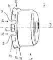
- the corresponding bayonet elements are formed as depressions 60, recesses or slots ( Fig. 1 or Fig. 4 ) extending essentially into the circumferential direction along the housing 4 with respect to the longitudinal axis A.
- the first housing 4 is connected with a second housing 41 by means of the bayonet connection elements.
- the bayonet connection elements are preferably projections or notches formed on the connection part 50 or alternatively in the first housing and/or the second housing, whereas preferably recesses (in the preferred embodiment recesses 44, 46) are formed in the second housing 4 and/or first housing 31.
- the projections 58 in the mounted state, are extending at least partly into depressions 60 formed within housing 4.
- the housing 4 can be rotated with respect to housing 31 and the connection part 50, so that the projections 58 come into form fit engagement with depressions 60.
- the port connectors 36, 38 are threaded into the threads 40, 42 and, in this state, block a rotation of housing 4 with respect to connection part 5 and thus with respect to housing 31.
- the break actuator 2 is safe by means of the mechanical connection.
- pressurized gas can be introduced through the gas inlet ports 32, 34.
- Each section B - G has a certain axial length into the axial direction of the longitudinal axis A.
- Section B includes the mechanical connection section 33 and the gas inlet port section 35 and has a relatively short axial dimension as illustrated by B ( Fig 2 ).
- Section B includes the mechanical connection section 33 and gas inlet port section 35 as well as the connection part 50 and gas inlet ports 32 and 34 and port connectors 36, 38.
- all bayonet connection elements in the form of the projections 58 see also Fig. 2 ) as well as the corresponding bayonet connections element in the form of depressions 60 formed within the protruding portion 48 of the housing 4 are provided within section B.
- the port connectors 36, 38 having the outer thread 40, 42 are mounted into the corresponding threads (not shown) formed within connection part 50.
- the port connectors 36, 38 and gas inlet ports 32 and 34 are each positioned between the projections 58 of the bayonet connection, regarded in a circumferential direction. Thus, no additional space is required into the axial direction (A), so that the length of section B is relatively small.
- section C illustrates a service break connection area or a section for connecting the service break (or service break section) 27 to the housing 4 and the connection part 50 of the mechanical connection section 33.
- a protruding section 54 interacts in a form fit connection or relationship with the upper part of flange 18 having the ring shaped protrusion 52.
- Section C is adjacent to section B.
- Section D shows the service break stroke and return spring area or section. It includes, amongst other elements, the service break spring 30.
- Section E is adjacent to section B and essentially defines the parking break stroke area or section within the parking break section 11 of the shown embodiment of the break actuator 2. Section E is used to move the corresponding spring break piston 10.
- Section F essentially illustrates the parking break storing area or section, within which the spring 8 of the parking break section 11 is active.
- Section G is adjacent to section F and essentially illustrates the release bolt or release rod 26 area.
- the essential axial dimension of the shown embodiment of the spring break actuator 2 is the sum of sections B - G.
- the overall length is reduced compared to other break actuators 2, because the mechanical connection section 33 and the gas inlet ports 32, 34 as well as the corresponding port connections 36, 38 are essentially positioned within the same section in the axial direction along axis A. At the same time, they are positioned essentially along the outer or circumferential sections of the housing or housings 4, 31, together with the connection part 50, which can be regarded as part of the overall housing of the spring break actuator 2.
Landscapes
- Engineering & Computer Science (AREA)
- General Engineering & Computer Science (AREA)
- Mechanical Engineering (AREA)
- Transportation (AREA)
- Braking Arrangements (AREA)
- Braking Systems And Boosters (AREA)
Priority Applications (3)
| Application Number | Priority Date | Filing Date | Title |
|---|---|---|---|
| EP21172409.1A EP4086127A1 (fr) | 2021-05-06 | 2021-05-06 | Actionneur de frein à ressort |
| CN202210479682.3A CN115306844A (zh) | 2021-05-06 | 2022-05-05 | 弹簧制动器促动器 |
| US17/737,161 US12090972B2 (en) | 2021-05-06 | 2022-05-05 | Spring brake actuator |
Applications Claiming Priority (1)
| Application Number | Priority Date | Filing Date | Title |
|---|---|---|---|
| EP21172409.1A EP4086127A1 (fr) | 2021-05-06 | 2021-05-06 | Actionneur de frein à ressort |
Publications (1)
| Publication Number | Publication Date |
|---|---|
| EP4086127A1 true EP4086127A1 (fr) | 2022-11-09 |
Family
ID=75825624
Family Applications (1)
| Application Number | Title | Priority Date | Filing Date |
|---|---|---|---|
| EP21172409.1A Pending EP4086127A1 (fr) | 2021-05-06 | 2021-05-06 | Actionneur de frein à ressort |
Country Status (3)
| Country | Link |
|---|---|
| US (1) | US12090972B2 (fr) |
| EP (1) | EP4086127A1 (fr) |
| CN (1) | CN115306844A (fr) |
Citations (4)
| Publication number | Priority date | Publication date | Assignee | Title |
|---|---|---|---|---|
| WO2008027018A1 (fr) * | 2006-08-29 | 2008-03-06 | Arfesan Arkan Fren Elemanlari Sanayi Ve Ticaret A. S | Cylindres de frein à ressort et à piston à diaphragme dotés d'éléments de raccordement inviolables pour le réservoir |
| DE102011115122A1 (de) * | 2011-10-07 | 2013-04-11 | Knorr-Bremse Systeme für Nutzfahrzeuge GmbH | Kombinierter Betriebsbrems- und Federspeicherbremszylinder mit Bajonettverschluss |
| WO2013169219A1 (fr) * | 2012-05-11 | 2013-11-14 | Arfesan Arkan Fren Elemanlari Sanayi Ve Ticaret A.S. | Système de raccordement de corps non détachable à bague de raccordement pour cylindres de frein d'urgence |
| DE102015115489A1 (de) * | 2015-09-15 | 2017-03-16 | Knorr-Bremse Systeme für Nutzfahrzeuge GmbH | Federspeicherbremszylinder mit doppelt abgedichtetem Bajonettverschluss |
Family Cites Families (21)
| Publication number | Priority date | Publication date | Assignee | Title |
|---|---|---|---|---|
| GB1126311A (en) | 1967-02-01 | 1968-09-05 | Certain Teed Prod Corp | Brake actuator |
| US3712181A (en) * | 1968-12-09 | 1973-01-23 | Certain Teed Prod Corp | Internal air assisted brake actuator |
| US3926094A (en) * | 1973-07-02 | 1975-12-16 | Midland Ross Corp | Air operated spring brake |
| DE3543365A1 (de) * | 1985-12-07 | 1987-06-11 | Wabco Westinghouse Fahrzeug | Bremszylinder |
| US5016523A (en) * | 1989-12-18 | 1991-05-21 | Anchorlok Corp. | Adjustable mounting apparatus for air-operated diaphragm brakes |
| EP0554050A1 (fr) * | 1992-01-28 | 1993-08-04 | Alliedsignal Limited | Cylindre de frein actionné par fluide |
| US5315918A (en) * | 1993-02-19 | 1994-05-31 | Nai Anchorlok, Inc. | Tamper-resistant brake actuator |
| US5829339A (en) * | 1995-06-09 | 1998-11-03 | Tse Brakes, Inc. | Crimped sealed adapter bushing assembly for a double diaphragm spring brake actuator |
| US5937974A (en) | 1997-05-02 | 1999-08-17 | Westinghouse Air Brake Company | Spring applied parking brake actuator having a collet style slack adjuster |
| US6050372A (en) * | 1998-03-18 | 2000-04-18 | Haldex Brake Corporation | Tamper-resistant brake actuator and method of making the same |
| AU2000278521A1 (en) * | 2000-03-15 | 2001-09-24 | Holland Neway International, Inc. | Sealed brake actuator |
| US7025385B2 (en) * | 2003-09-03 | 2006-04-11 | United Technologies Corporation | Coupling |
| CN102032298A (zh) | 2010-12-22 | 2011-04-27 | 芜湖盛力制动有限责任公司 | 一种卡车制动系统的膜片式弹簧制动气室 |
| CN202301649U (zh) | 2011-11-04 | 2012-07-04 | 宁波神丰汽车部件有限公司 | 活塞式弹簧制动室的释放机构 |
| US9688261B2 (en) | 2012-03-16 | 2017-06-27 | Haldex Brake Products Corporation | Spring brake actuator with a caging bolt bearing joining a pressure plate and actuator tube |
| KR101567709B1 (ko) * | 2014-07-11 | 2015-11-10 | (주)지앤피오토모티브 | 브레이크 액추에이터 |
| CN104405800A (zh) | 2014-12-20 | 2015-03-11 | 芜湖盛力科技股份有限公司 | 一种商用车制动系统膜片式弹簧制动气室 |
| DE102017114664B4 (de) | 2017-06-30 | 2023-03-02 | Knorr-Bremse Systeme für Schienenfahrzeuge GmbH | Federspeicherbremszylinder mit einer Notlöseeinrichtung |
| EP3620334B8 (fr) | 2018-09-05 | 2021-06-23 | ZF CV Systems Europe BV | Actionneur de frein pour un véhicule utilitaire et systeme de freinage equipe d'un tel actionneur |
| WO2020194078A1 (fr) * | 2019-03-27 | 2020-10-01 | Wabco India Limited | Actionneur de frein à ressort pour un véhicule, en particulier actionneur de frein de stationnement ou d'urgence destiné à être utilisé dans un véhicule utilitaire |
| CN112682440A (zh) | 2019-10-17 | 2021-04-20 | 威伯科印度有限公司 | 包括集成阀单元的弹簧制动器促动器 |
-
2021
- 2021-05-06 EP EP21172409.1A patent/EP4086127A1/fr active Pending
-
2022
- 2022-05-05 US US17/737,161 patent/US12090972B2/en active Active
- 2022-05-05 CN CN202210479682.3A patent/CN115306844A/zh active Pending
Patent Citations (4)
| Publication number | Priority date | Publication date | Assignee | Title |
|---|---|---|---|---|
| WO2008027018A1 (fr) * | 2006-08-29 | 2008-03-06 | Arfesan Arkan Fren Elemanlari Sanayi Ve Ticaret A. S | Cylindres de frein à ressort et à piston à diaphragme dotés d'éléments de raccordement inviolables pour le réservoir |
| DE102011115122A1 (de) * | 2011-10-07 | 2013-04-11 | Knorr-Bremse Systeme für Nutzfahrzeuge GmbH | Kombinierter Betriebsbrems- und Federspeicherbremszylinder mit Bajonettverschluss |
| WO2013169219A1 (fr) * | 2012-05-11 | 2013-11-14 | Arfesan Arkan Fren Elemanlari Sanayi Ve Ticaret A.S. | Système de raccordement de corps non détachable à bague de raccordement pour cylindres de frein d'urgence |
| DE102015115489A1 (de) * | 2015-09-15 | 2017-03-16 | Knorr-Bremse Systeme für Nutzfahrzeuge GmbH | Federspeicherbremszylinder mit doppelt abgedichtetem Bajonettverschluss |
Also Published As
| Publication number | Publication date |
|---|---|
| CN115306844A (zh) | 2022-11-08 |
| US12090972B2 (en) | 2024-09-17 |
| US20220355775A1 (en) | 2022-11-10 |
Similar Documents
| Publication | Publication Date | Title |
|---|---|---|
| JP5591936B2 (ja) | 二重内接歯車ポンプ | |
| US9073527B2 (en) | Smooth bore dynamic center seal for spring brake actuator | |
| US9487200B2 (en) | Combined service brake cylinder and spring brake cylinder having a bayonet coupling | |
| US7390174B2 (en) | Piston pump | |
| JP2018520010A (ja) | 軸のカシメ工具 | |
| AU687060B2 (en) | Spring brake actuator, caging bolt assembly therefor, and method of assembly thereof | |
| EP4015323A2 (fr) | Actionneur de frein à ressort destiné à être utilisé dans un véhicule utilitaire et véhicule utilitaire le comprenant | |
| US20120073282A1 (en) | Hydraulic system | |
| US5725076A (en) | Spring brake actuator and caging bolt therefor | |
| EP4086127A1 (fr) | Actionneur de frein à ressort | |
| US20080083325A1 (en) | Mid-power spring brake actuator having fuse-collar design for safety | |
| EP4069563B1 (fr) | Actionneur de frein à ressort | |
| CN112112912B (zh) | 弹簧制动器促动器和用于这种弹簧制动器促动器的制动器释放机构 | |
| WO1994021892A1 (fr) | Coussinet d'etancheite pour cylindre de frein hydraulique | |
| EP3406928A1 (fr) | Ressort appliqué, frein desserré hydrauliquement avec surpassement manuel | |
| EP4023512B1 (fr) | Siège à ressort estampé destiné à être utilisé dans un actionneur de frein à ressort et actionneur de frein à ressort destiné à être utilisé dans des véhicules utilitaires | |
| EP4071015B1 (fr) | Actionneur de frein à ressort pneumatique | |
| EP4222032B1 (fr) | Soupape de frein à main, système de freinage pneumatique, véhicule, méthode de montage d'une soupape de frein à main | |
| US9981646B2 (en) | Brake cylinder | |
| EP4733161A1 (fr) | Actionneur de frein à ressort pour un système de freinage pneumatique d'un véhicule, en particulier véhicule utilitaire, système de freinage pneumatique, véhicule et procédé | |
| CN216761719U (zh) | 一种带防错定位的刹车系统阀壳体 | |
| WO2021222101A1 (fr) | Actionneur de frein utilisant une vessie ou des vessies de fluide en tant que chambres de fluide | |
| WO2000030913A1 (fr) | Plateau de pression en deux parties et son procede de fabrication | |
| US7197874B2 (en) | Plunger master brake cylinder | |
| CN113784879A (zh) | 用于弹簧制动促动器的活塞管组件以及弹簧制动促动器 |
Legal Events
| Date | Code | Title | Description |
|---|---|---|---|
| PUAI | Public reference made under article 153(3) epc to a published international application that has entered the european phase |
Free format text: ORIGINAL CODE: 0009012 |
|
| STAA | Information on the status of an ep patent application or granted ep patent |
Free format text: STATUS: THE APPLICATION HAS BEEN PUBLISHED |
|
| AK | Designated contracting states |
Kind code of ref document: A1 Designated state(s): AL AT BE BG CH CY CZ DE DK EE ES FI FR GB GR HR HU IE IS IT LI LT LU LV MC MK MT NL NO PL PT RO RS SE SI SK SM TR |
|
| STAA | Information on the status of an ep patent application or granted ep patent |
Free format text: STATUS: REQUEST FOR EXAMINATION WAS MADE |
|
| 17P | Request for examination filed |
Effective date: 20230509 |
|
| RBV | Designated contracting states (corrected) |
Designated state(s): AL AT BE BG CH CY CZ DE DK EE ES FI FR GB GR HR HU IE IS IT LI LT LU LV MC MK MT NL NO PL PT RO RS SE SI SK SM TR |
|
| STAA | Information on the status of an ep patent application or granted ep patent |
Free format text: STATUS: EXAMINATION IS IN PROGRESS |
|
| 17Q | First examination report despatched |
Effective date: 20240513 |