EP4086145B1 - Fahrzeugaussenluftführungsvorrichtung und verfahren zum zusammenbau einer solchen aussenluftführungsvorrichtung - Google Patents
Fahrzeugaussenluftführungsvorrichtung und verfahren zum zusammenbau einer solchen aussenluftführungsvorrichtung Download PDFInfo
- Publication number
- EP4086145B1 EP4086145B1 EP21305579.1A EP21305579A EP4086145B1 EP 4086145 B1 EP4086145 B1 EP 4086145B1 EP 21305579 A EP21305579 A EP 21305579A EP 4086145 B1 EP4086145 B1 EP 4086145B1
- Authority
- EP
- European Patent Office
- Prior art keywords
- movable part
- axis
- air guiding
- guiding device
- link bar
- Prior art date
- Legal status (The legal status is an assumption and is not a legal conclusion. Google has not performed a legal analysis and makes no representation as to the accuracy of the status listed.)
- Active
Links
Images



Classifications
-
- B—PERFORMING OPERATIONS; TRANSPORTING
- B62—LAND VEHICLES FOR TRAVELLING OTHERWISE THAN ON RAILS
- B62D—MOTOR VEHICLES; TRAILERS
- B62D35/00—Vehicle bodies characterised by streamlining
- B62D35/007—Rear spoilers
-
- B—PERFORMING OPERATIONS; TRANSPORTING
- B62—LAND VEHICLES FOR TRAVELLING OTHERWISE THAN ON RAILS
- B62D—MOTOR VEHICLES; TRAILERS
- B62D27/00—Connections between superstructure or understructure sub-units
- B62D27/06—Connections between superstructure or understructure sub-units readily releasable
- B62D27/065—Connections between superstructure or understructure sub-units readily releasable using screwthread
-
- B—PERFORMING OPERATIONS; TRANSPORTING
- B62—LAND VEHICLES FOR TRAVELLING OTHERWISE THAN ON RAILS
- B62D—MOTOR VEHICLES; TRAILERS
- B62D35/00—Vehicle bodies characterised by streamlining
-
- B—PERFORMING OPERATIONS; TRANSPORTING
- B62—LAND VEHICLES FOR TRAVELLING OTHERWISE THAN ON RAILS
- B62D—MOTOR VEHICLES; TRAILERS
- B62D37/00—Stabilising vehicle bodies without controlling suspension arrangements
- B62D37/02—Stabilising vehicle bodies without controlling suspension arrangements by aerodynamic means
-
- B—PERFORMING OPERATIONS; TRANSPORTING
- B62—LAND VEHICLES FOR TRAVELLING OTHERWISE THAN ON RAILS
- B62D—MOTOR VEHICLES; TRAILERS
- B62D65/00—Designing, manufacturing, e.g. assembling, facilitating disassembly, or structurally modifying motor vehicles or trailers, not otherwise provided for
- B62D65/02—Joining sub-units or components to, or positioning sub-units or components with respect to, body shell or other sub-units or components
- B62D65/16—Joining sub-units or components to, or positioning sub-units or components with respect to, body shell or other sub-units or components the sub-units or components being exterior fittings, e.g. bumpers, lights, wipers, exhausts
-
- Y—GENERAL TAGGING OF NEW TECHNOLOGICAL DEVELOPMENTS; GENERAL TAGGING OF CROSS-SECTIONAL TECHNOLOGIES SPANNING OVER SEVERAL SECTIONS OF THE IPC; TECHNICAL SUBJECTS COVERED BY FORMER USPC CROSS-REFERENCE ART COLLECTIONS [XRACs] AND DIGESTS
- Y02—TECHNOLOGIES OR APPLICATIONS FOR MITIGATION OR ADAPTATION AGAINST CLIMATE CHANGE
- Y02T—CLIMATE CHANGE MITIGATION TECHNOLOGIES RELATED TO TRANSPORTATION
- Y02T10/00—Road transport of goods or passengers
- Y02T10/80—Technologies aiming to reduce greenhouse gasses emissions common to all road transportation technologies
- Y02T10/82—Elements for improving aerodynamics
Definitions
- the present invention relates to a vehicle exterior air guiding device intended to be installed on a motor vehicle comprising :
- Such an exterior air guiding device is for example a spoiler mounted on the rear part of the motor vehicle.
- a movable air guiding device arrangement is often complex, requires many parts, which makes it cumbersome and expensive.
- One of the aims of the invention is to provide a mobile exterior air guiding device easy to mount in a robust way on a motor vehicle while being difficult to remove once mounted on the motor vehicle.
- the invention proposes an air guiding device of the afore-mentioned type, wherein the assembling device comprises one fastening element extending along a fastening axis and locking the link bar in position, the bar axis and the fastening axis extending in different directions.
- the assembling device composed of a link bar locked by one fastening element makes the assembly of the connecting mechanism on the movable part very easy simply by putting the link bar in place and then lock it.
- the exterior air guiding device comprises one or several following features, taken individually or in any technically feasible combination:
- the invention further relates to a method for assembling such an exterior air guiding device on a motor vehicle, the method comprising at least the following steps, for each connecting mechanism:
- the terms “lower”, “upper”, “transverse”, “front”, “rear” are defined in the usual directions of an assembled vehicle, these terms referring, if applicable, to the position of the air guiding device when it is assembled on the vehicle.
- the transverse direction refers to a direction that extends substantially perpendicular to the movement direction of the vehicle.
- inner refers to what faces the body of the vehicle and the term “outer” to what faces the outside of the vehicle when the air guiding device is assembled on the vehicle.
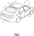
- Figure 1 and 2 shows a motor vehicle 10 comprising a body 12 and an exterior air guiding device 14.
- the motor vehicle 10 is for example a car, a bus, a van or a truck.
- the body 12 of the motor vehicle 10 delimits an exterior space and an interior space intended notably for receiving passengers.
- the body 12 of the motor vehicle 10 comprises a front part 16, a rear part 18 and a roof 20 extending between the front part 16 and the rear part 18.
- the air guiding device 14 is installed on the exterior space and for example on the rear part 18 of the body 12.
- the air guiding device 14 is a spoiler installed between the vehicle roof 20 and the rear windshield.
- the air guiding device 14 is, for example, a spoiler installed on the trunk of the vehicle, or a rear diffuser installed under the rear part 18 of the body 12.
- the air guiding device 14 is a spoiler installed on the front part 16 of the body 12.
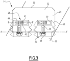
- the exterior air guiding device 14 comprises a fixed part 22, a movable part 24 mounted on the fixed part 22, at least one connecting mechanism 26 allowing a movement of the movable part 24 relative to the fixed part 22 and for each connecting mechanism 26, an assembling device 28 for connecting the connecting mechanism 26 to the movable part 24.
- the fixed part 22 is attached to the body 12 of the motor vehicle 10.
- the fixed part 22 is fastened directly to the rear part 18 of the body 12 or, as shown in Figures 1 and 2 is part of the body 12.
- the movable part 24 is movably mounted on the fixed part 22.
- the movable part 24 is mounted for example in a rotating manner about a transverse axis A-A' relative to the fixed part 22 between a stowed position and a deployed position, as illustrated in figures 1 and 2 .
- the connecting mechanism 26 is formed by a hinge connecting the movable part 24 to the fixed part 22.
- the rotation angle of the movable part 24 between the stowed position and the deployed position is for example comprised between 10° and 90°.
- the movable part 24 is mounted in translation along the transverse axis A-A' relative to the fixed part 22 between the stowed position and the deployed position.
- the connecting mechanism 26 is for example formed by a rail allowing the movable part 24 to slide relative to the fixed part 22.
- the movement of the movable part 24 relative to the fixed part 22 between the stowed position and the deployed position is a combination of a translation along the transverse axis A-A' and a rotation with the transverse axis A-A' as rotation axis.
- the transverse axis A-A' defines thus a rotation axis and/or a translation axis of the movable part 24 relative to the fixed part 22.
- the movable part 24 comprises an air guiding face 30 and an opposite face 32 that is substantially opposite to the air guiding face 30.
- the air guiding face 30 guides the flow of air following the curves of the rear part 18 of the body 12.
- the air guiding face 30 when the movable part 14 is in the stowed position, the air guiding face 30 extends substantially in the continuation of the fixed part 22. "In the continuation" means that the air guiding face 30 and the fixed part 22 together form a substantially continuous and regular air-guiding surface.
- the movable part 24 occupies the stowed position when the speed of the motor vehicle is low, for example less than 50 km/h.
- the air guiding face 30 guides the flow of air away from the rear part 18 of the body 12.
- the opposite face 32 is not in contact with the fixed part 22.
- the air guiding face 30 is inclined relative to the fixed part 22.
- the movable part 24 occupies the deployed position when the speed of the motor vehicle is important, for example above 60 km/h.
- the movable part 24 moves from the stowed position toward the deployed position when the speed of the motor vehicle increases, for example exceeds 60 km/h, and the movable part 24 moves from the deployed position toward the stowed position when the speed of the motor vehicle decreases for example falls below 40 km/h.
- the air guiding face 30 has for example a substantially flat shape. In a variant, it has a convex or concave shape.
- connecting mechanism(s) 26 is(are) or comprise(s) a hinge
- each connecting mechanism 26 comprises a first portion 34 fastened on the fixed part 22, a second portion 36 mounted on the movable part 24 and an articulating mean 38.
- the articulating mean 38 comprises for example, in a well-known manner, knuckles and a pin allowing the rotation of the second portion 36 relative to the first portion 34, and thus the rotation of the movable part 24 relative to the fixed part 22 along the transverse axis A-A'.
- the articulating mean 38 defines a slide rail allowing the translation of the second portion 36 relative to the first portion 34 and thus the translation of the movable part 24 relative to the fixed part 22 along the transverse axis A-A'.
- each connecting mechanism 26 is mounted on the movable part 24 by means of an assembling device 28.
- the assembling device 28 comprises a link bar 40 and one fastening element 41.
- the link bar 40 extends along a bar axis B-B'.
- the bar axis B-B' is substantially parallel to the transverse axis A-A'.
- the link bar 40 comprises advantageously a fastening head 42 and a rod 44 extending from the fastening head 42 along the bar axis B-B'.
- the fastening head 42 is located at one end of the rod 44.
- the rod 44 for example has a circular cross-section with a diameter substantially comprised between 2 mm and 12 mm.
- the rod 44 has for example a length, measured along the bar axis B-B', substantially comprised between 20 mm and 100 mm.
- the fastening head 42 is, for example, substantially rectangular in shape with lateral dimensions greater than the diameter of the rod 44 such that the fastening head 42 protrudes radially from the rod 44.
- the link bar 40 is for example made of metal.
- the link bar 40 is inserted in at least one opening 46 defined in the movable part 24 and in at least one opening 48 defined in the connecting mechanism 26.
- the link bar 40 is inserted into two openings 46 defined in the movable part 24 and into one opening 48 defined in the connecting mechanism 26, and more specifically defined in the second portion 36 of the connecting mechanism 26.
- the link bar 40 is inserted into two openings defined in the connecting mechanism 26 and into one opening defined in the movable part.
- the three openings 46, 48 are aligned along the bar axis B-B' and the opening 48 defined in the connecting mechanism 26 is located between the two openings 46 defined in the movable part 24.More specifically, when the assembling device 28 is mounted as shown on Figure 5 , the rod 44 is inserted in the three openings 46, 48 and the fastening head 42 is located close to one of the openings defined in the movable part 24.
- two protruding housings 50 are defined on the movable part 24, and more specifically on the opposite face 32 of the movable part 24.
- Each one of the housings 50 defines a space to receive a part of the link bar 40.
- Each one of the housings 50 comprises one of the two openings 46 for the passage of the link bar 40.
- a rail 56 is defined at least in one of the housings 50 in order to guide the insertion of the link bar 40 in the openings 46, 48.
- Such a geometry of the housing 50 allows a simplified positioning of the link bar 40.
- such a geometry of the housing 50, and more specifically the rail 56 makes it possible to hold the link bar 40 inside said housing 50, even before the definitive fastening of the link bar 40.
- the movable part 24 has for example the shape of a fork with two branches, each branches defining a housing 50.
- Each opening 46 is preferably defined on a lateral side 52 of one of the housing 50.
- the two housings 50 define between them a cavity 54, corresponding for example to the space between the two branches of the fork. More specifically, the cavity 54 is defined as the space between two lateral sides 52 in which the openings 46 are defined. Said two lateral sides 52 are facing each other.
- the part of the connecting mechanism 26, and more specifically of the second portion 36, in which the opening 48 is defined is received into said cavity 54, so that the three openings 46, 48 are aligned and the link bar 40, and more specifically the rod 48, extends in the openings 46, 48 along the bar axis B-B'.
- the fastening head 42 lies preferably against one of the lateral sides 52 in which an opening 46 is defined.
- the fastening element 41 locks the link bar 40 in position, such that all rotation and translation movements of the link bar 40 relative to bar axis B-B' are blocked.
- the fastening element 41 extends along a fastening axis F-F'.
- the bar axis B-B' and the fastening axis F-F' are distinct from each other, meaning that they extend in different directions.
- the bar axis and the fastening axis are not parallel to each other.
- the bar axis and the fastening axis are substantially perpendicular.
- the fastening element 41 fastens the link bar 40, and more specifically the fastening head 42, to the movable part 24, and more specifically to one of the housing 50.
- the fastening element 41 is preferably a screw. In variant, the fastening element 41 is a bolt.
- a threaded hole 58 is defined in the fastening head 42.
- the screw 41 is screwed into said threaded hole 58.
- the air guiding device 14 device further comprises a sealing system 60.
- the sealing system 60 is for example a rubber boot fixed to the movable part 24 and to the fixed part 22.
- the assembling device 28 and the connecting mechanism 26 are advantageously located inside said sealing system 60.
- Said sealing system 60 is flexible, such that so that it is able to adapt its shape according to the position of the movable part 24.
- the fixed part 22 of the exterior air guiding device 14 is fastened to the body 12 on the exterior side, and for example to the rear part 18 of the body 12.
- the fixed part 22 is fastened between the roof 20 and the rear windshield.
- At least one connecting mechanism 26, and more specifically the first portion 34 of each connecting mechanism 26, is fastened on the fixed part 22.
- an assembling device 28 comprising a link bar 40 and a fastening element 41 is provided.
- the link bar 40 is placed close to one of the openings 46 defined in the movable part 24, and more particularly on the opposite face 32.
- the link bar 40 is preferably inserted into the rail 56 defining in one of the housing 50.
- the movable part 24 is placed on the connecting mechanism 26.
- the part of the connecting mechanism 26, and more specifically of the second portion 36, in which the opening 48 is defined is received into the cavity 54 defined between the two housings 50.
- the link bar 40 is then pushed along the bar axis B-B', so that the link bar 40 passes through the openings 46, 48, and more specifically through the three openings 46, 48.
- the link bar 40 extends preferably along the bar axis B-B' parallel to the transverse axis A-A.
- the transverse axis A-A' defines the rotation axis and/or the translation axis of the movable part 24 relative to the fixed part 22.
- the fastening head 42 of the link bar 40 lies against one of the lateral sides 52 in which an opening 46 is defined.
- the fastening element 41 preferably a screw, extends along the fastening axis F-F' distinct from the bar axis B-B', and more specifically perpendicular to said bar axis B-B'.
- the fastening element 41 is a screw screwed into a threaded hole 58 defined in the fastening head 42 of the link bar 40.
- a sealing system 60 is then installed and fixed.
- the sealing system 60 constituting of a rubber boot is first clipped to the movable part 24, more specifically into a trail defined in the movable part 24, for a fixation in a form-fitting manner.
- the rubber boot is fastened to the fixed part 22, advantageously thanks to invisible fixing.
- the fixing of the rubber boot to the fixed part 22 is not visible from the outside of the rubber boot.
- Such an exterior air guiding device 14 is easy to assemble, notably thanks to the assembling device 28 composed only of a link bar 40 and one screw 41. The assembly cost are therefore reduced.
- such an assembling device 28 ensures a robust and reliable assembly of the movable part 24 on the connecting mechanism 26.
- such an assembling device 28 is space-saving while ensuring good resistance to effort, notably thanks to the fastening element 41 extending along a fastening axis F-F' extending in a different direction than the transverse axis A-A'. This resistance is even more increased when the fastening axis is perpendicular to the transverse axis A-A'.
- the assembling device 28 is located on the opposite face 32, which is in contact with the fixed part 22 when the movable part 24 is in its stowed position.
- the assembling device 28 and in particular, the fastening element 41 is thus difficult to access, which makes it difficult to remove and thus protects the device from vandalism.
Landscapes
- Engineering & Computer Science (AREA)
- Chemical & Material Sciences (AREA)
- Combustion & Propulsion (AREA)
- Transportation (AREA)
- Mechanical Engineering (AREA)
- Manufacturing & Machinery (AREA)
- Physics & Mathematics (AREA)
- Fluid Mechanics (AREA)
- Air-Conditioning For Vehicles (AREA)
- Cooling, Air Intake And Gas Exhaust, And Fuel Tank Arrangements In Propulsion Units (AREA)
- Power-Operated Mechanisms For Wings (AREA)
Claims (10)
- Fahrzeugaußenluft-Leitvorrichtung, die zum Einbau in ein Kraftfahrzeug (10) bestimmt ist, umfassend:- einen feststehenden Teil (22), das dazu bestimmt ist, an dem Kraftfahrzeug (10) befestigt zu werden,- einen beweglichen Teil (24), der beweglich an dem festen Teil (22) befestigt ist,- mindestens einen Verbindungsmechanismus (26), der eine Bewegung des beweglichen Teils (24) relativ zum feststehenden Teil (22) zwischen einer Verstauposition und einer Einsatzposition ermöglicht, und,- für jeden Verbindungsmechanismus (26), eine Montagevorrichtung (28) zum Verbinden des Verbindungsmechanismus (26) und des beweglichen Teils (24), wobei die Montagevorrichtung (28) eine Verbindungsstange (40) umfasst, die sich entlang einer Stangenachse (B-B') erstreckt, die Verbindungsstange (40) in mindestens eine in dem beweglichen Teil (24) definierte Öffnung (46) und in mindestens eine in dem Verbindungsmechanismus (26) definierte Öffnung (48) eingesetzt ist,dadurch gekennzeichnet, dass die Montagevorrichtung (28) ein Befestigungselement (41) umfasst, das sich entlang einer Befestigungsachse (F-F') erstreckt und die Verbindungsstange (40) in ihrer Position arretiert, wobei die Stangenachse (B-B') und die Befestigungsachse (F-F') in unterschiedliche Richtungen verlaufen.
- Außenluft-Leitvorrichtung nach Anspruch 1, dadurch gekennzeichnet, dass die Stangenachse (B-B') im Wesentlichen parallel zu einer Querachse (A-A' verläuft, wobei die Querachse (A-A') eine Rotationsachse und/oder eine Translationsachse des beweglichen Teils (24) relativ zum feststehenden Teil (22) definiert.
- Außenluft-Leitvorrichtung nach Anspruch 1 oder 2, wobei die Stangenachse (B-B') und die Befestigungsachse (F-F') im Wesentlichen senkrecht zueinander stehen.
- Außenluft-Leitvorrichtung nach einem der Ansprüche 1 bis 3, wobei das Befestigungselement (41) eine Schraube ist.
- Außenluft-Leitvorrichtung nach einem der Ansprüche 1 bis 4, dadurch gekennzeichnet, dass die Verbindungsstange (40) in zwei im beweglichen Teil (24) ausgebildete Öffnungen (46) und in eine im Verbindungsmechanismus (26) ausgebildete Öffnung (48) eingesetzt ist, wobei die drei Öffnungen (46, 48) entlang der Stangenachse (B-B') ausgerichtet sind und die im Verbindungsmechanismus (26) ausgebildete Öffnung (48) zwischen den beiden im beweglichen Teil (24) ausgebildeten Öffnungen (46) angeordnet ist.
- Außenluft-Leitvorrichtung nach Anspruch 5, dadurch gekennzeichnet, dass der bewegliche Teil (24) für jeden Verbindungsmechanismus (26) zwei getrennte, vorstehende Gehäuse (50) aufweist, die jeweils eine der beiden Öffnungen (46) des beweglichen Teils (24) für den Durchgang der Verbindungsstange (40) umfassen, wobei die beiden Gehäuse (50) zwischen sich einen Hohlraum (54) zur Aufnahme eines Teils des Verbindungsmechanismus (26) definieren, in dem die Öffnung (48) für den Durchgang der Verbindungsstange (40) definiert ist.
- Außenluft-Leitvorrichtung nach einem der Ansprüche 1 bis 6, wobei die Verbindungsstange (40) einen Befestigungskopf (42) aufweist und dieser Befestigungskopf (42) über das Befestigungselement (41) an dem beweglichen Teil (24) befestigt ist.
- Außenluft-Leitvorrichtung nach einem der Ansprüche 4 und 7, wobei im Befestigungskopf (42) eine Gewindebohrung (58) ausgebildet ist und die Schraube (41) in diese Gewindebohrung (58) des Befestigungskopfes (42) der Verbindungsstange (40) eingeschraubt wird.
- Außenluft-Leitvorrichtung nach einem der Ansprüche 1 bis 8, ferner umfassend ein Abdichtungssystem (60).
- Verfahren zum Montieren einer Außenluft-Leitvorrichtung nach einem der Ansprüche 1 bis 9 an einem Kraftfahrzeug, wobei das Verfahren für jeden Verbindungsmechanismus (26) mindestens die folgenden Schritte umfasst:- Anbringen der Verbindungsstange (40) in der Nähe einer im beweglichen Teil (24) ausgebildeten Öffnung (46);- Platzieren des beweglichen Teils (24) am Verbindungsmechanismus (26);- Verschieben der Verbindungsstange (40) entlang der Stangenachse (B-B'), sodass die Verbindungsstange (40) durch die Öffnungen (46, 48) hindurchgeht; und- Arretieren der Verbindungsstange (40) in ihrer Position mithilfe des Befestigungselements (41), das sich entlang der Befestigungsachse (F'F') erstreckt, die sich in einer anderen Richtung als die Stangenachse (B-B') erstreckt.
Priority Applications (4)
| Application Number | Priority Date | Filing Date | Title |
|---|---|---|---|
| EP21305579.1A EP4086145B1 (de) | 2021-05-05 | 2021-05-05 | Fahrzeugaussenluftführungsvorrichtung und verfahren zum zusammenbau einer solchen aussenluftführungsvorrichtung |
| ES21305579T ES3037756T3 (en) | 2021-05-05 | 2021-05-05 | A vehicle exterior air guiding device and method for assembling such an exterior air guiding device |
| US18/559,340 US20240239424A1 (en) | 2021-05-05 | 2022-05-04 | A vehicle exterior air guiding device and method for assembling such an exterior air guiding device |
| PCT/EP2022/062020 WO2022233959A1 (en) | 2021-05-05 | 2022-05-04 | A vehicle exterior air guiding device and method for assembling such an exterior air guiding device |
Applications Claiming Priority (1)
| Application Number | Priority Date | Filing Date | Title |
|---|---|---|---|
| EP21305579.1A EP4086145B1 (de) | 2021-05-05 | 2021-05-05 | Fahrzeugaussenluftführungsvorrichtung und verfahren zum zusammenbau einer solchen aussenluftführungsvorrichtung |
Publications (2)
| Publication Number | Publication Date |
|---|---|
| EP4086145A1 EP4086145A1 (de) | 2022-11-09 |
| EP4086145B1 true EP4086145B1 (de) | 2025-06-25 |
Family
ID=75904856
Family Applications (1)
| Application Number | Title | Priority Date | Filing Date |
|---|---|---|---|
| EP21305579.1A Active EP4086145B1 (de) | 2021-05-05 | 2021-05-05 | Fahrzeugaussenluftführungsvorrichtung und verfahren zum zusammenbau einer solchen aussenluftführungsvorrichtung |
Country Status (4)
| Country | Link |
|---|---|
| US (1) | US20240239424A1 (de) |
| EP (1) | EP4086145B1 (de) |
| ES (1) | ES3037756T3 (de) |
| WO (1) | WO2022233959A1 (de) |
Families Citing this family (1)
| Publication number | Priority date | Publication date | Assignee | Title |
|---|---|---|---|---|
| CN118833303A (zh) * | 2023-04-24 | 2024-10-25 | 本田技研工业株式会社 | 车辆控制系统 |
Family Cites Families (10)
| Publication number | Priority date | Publication date | Assignee | Title |
|---|---|---|---|---|
| CN110450863B (zh) * | 2014-06-11 | 2022-09-16 | 麦格纳外饰公司 | 用于车辆的连杆组件 |
| CA2952371C (en) * | 2014-06-11 | 2021-12-07 | Magna Exteriors Inc. | Active front deflector |
| CN107848582B (zh) * | 2015-09-23 | 2020-03-03 | 多媒体股份有限公司 | 用于车辆的抗负载扰流板机构 |
| US9950751B2 (en) * | 2015-09-25 | 2018-04-24 | GM Global Technology Operations LLC | Aerodynamic system and method for diagnosing the aerodynamic system and verify downforce estimation based on electric motor current |
| DE102016210407B4 (de) * | 2016-06-13 | 2022-12-01 | Röchling Automotive SE & Co. KG | Frontspoiler-Anordnung mit als Überlastschutz vom Bewegungsantrieb entkoppelbarem Strömungsleitbauteil |
| US10035548B2 (en) * | 2016-08-10 | 2018-07-31 | GM Global Technology Operations LLC | Active spoiler for a motor vehicle |
| KR102518233B1 (ko) * | 2016-11-15 | 2023-04-07 | 현대자동차주식회사 | 차량용 리어 범퍼의 가변 스포일러 장치 |
| DE102017214769A1 (de) * | 2017-08-23 | 2019-02-28 | Röchling Automotive SE & Co. KG | Aktiver Radspoiler |
| CN116198616A (zh) * | 2018-06-21 | 2023-06-02 | 麦格纳外饰公司 | 主动式空气动力学应用扭矩驱动连杆 |
| US12570364B2 (en) * | 2021-12-02 | 2026-03-10 | Ventra Group Co. | Active air dam system with object impact damage control |
-
2021
- 2021-05-05 EP EP21305579.1A patent/EP4086145B1/de active Active
- 2021-05-05 ES ES21305579T patent/ES3037756T3/es active Active
-
2022
- 2022-05-04 WO PCT/EP2022/062020 patent/WO2022233959A1/en not_active Ceased
- 2022-05-04 US US18/559,340 patent/US20240239424A1/en active Pending
Also Published As
| Publication number | Publication date |
|---|---|
| ES3037756T3 (en) | 2025-10-06 |
| US20240239424A1 (en) | 2024-07-18 |
| WO2022233959A1 (en) | 2022-11-10 |
| EP4086145A1 (de) | 2022-11-09 |
Similar Documents
| Publication | Publication Date | Title |
|---|---|---|
| EP3007919B1 (de) | Trägerstruktur für fensterscheibe | |
| US7984944B2 (en) | Fender for a motor vehicle | |
| US20090066096A1 (en) | Vehicle grille including structural inner and decorative outer snap-in features with, and/or method of making the same | |
| US20120038254A1 (en) | Overhead luggage compartment | |
| US7967373B2 (en) | Vehicle body of a motor vehicle with a front-end module | |
| EP4086145B1 (de) | Fahrzeugaussenluftführungsvorrichtung und verfahren zum zusammenbau einer solchen aussenluftführungsvorrichtung | |
| US20050082880A1 (en) | High roof structure of a vehicle | |
| US7237411B2 (en) | Operating device for a motor vehicle door lock | |
| JP6177772B2 (ja) | 自動車のための側部保護デバイスおよび関連する自動車 | |
| EP3684993B1 (de) | Kraftfahrzeugverriegelung | |
| US7438351B2 (en) | Structural element comprising a vertical member securing nut and the corresponding motor vehicle | |
| US20020167288A1 (en) | Wiper system for motor vehicles | |
| CN107620530B (zh) | 用于车门组件的具有弹簧锁基准定位器的把手底架 | |
| US7404579B2 (en) | Arrangement for the step-by-step height adjustment of a holding or deflecting fitting of a seat belt on a hollow body part of a motor vehicle | |
| US7287786B2 (en) | Locking device for a vehicle door | |
| KR102159061B1 (ko) | 에어백 하우징용 마운팅 클립 어셈블리 | |
| US12415481B2 (en) | Fascia door and washer fluid reservoir | |
| US20080289154A1 (en) | Device and Method for Fixing a Trim Component on a Motor Vehicle Recess Post | |
| US9914434B2 (en) | Wiper apparatus | |
| CN223989937U (zh) | 车门加强组件、车门及车辆 | |
| US20250043600A1 (en) | Motor vehicle lock - in particular, motor vehicle side door lock | |
| CN114206644B (zh) | 车门的门模块 | |
| WO2024214566A1 (ja) | 車両部品の締結構造 | |
| KR100520773B1 (ko) | 자동차의 도어 가니쉬 보강재의 장착구조 | |
| CN121291280A (zh) | 交通工具存储装置 |
Legal Events
| Date | Code | Title | Description |
|---|---|---|---|
| PUAI | Public reference made under article 153(3) epc to a published international application that has entered the european phase |
Free format text: ORIGINAL CODE: 0009012 |
|
| STAA | Information on the status of an ep patent application or granted ep patent |
Free format text: STATUS: THE APPLICATION HAS BEEN PUBLISHED |
|
| AK | Designated contracting states |
Kind code of ref document: A1 Designated state(s): AL AT BE BG CH CY CZ DE DK EE ES FI FR GB GR HR HU IE IS IT LI LT LU LV MC MK MT NL NO PL PT RO RS SE SI SK SM TR |
|
| STAA | Information on the status of an ep patent application or granted ep patent |
Free format text: STATUS: REQUEST FOR EXAMINATION WAS MADE |
|
| 17P | Request for examination filed |
Effective date: 20230425 |
|
| RBV | Designated contracting states (corrected) |
Designated state(s): AL AT BE BG CH CY CZ DE DK EE ES FI FR GB GR HR HU IE IS IT LI LT LU LV MC MK MT NL NO PL PT RO RS SE SI SK SM TR |
|
| GRAP | Despatch of communication of intention to grant a patent |
Free format text: ORIGINAL CODE: EPIDOSNIGR1 |
|
| STAA | Information on the status of an ep patent application or granted ep patent |
Free format text: STATUS: GRANT OF PATENT IS INTENDED |
|
| INTG | Intention to grant announced |
Effective date: 20250310 |
|
| GRAS | Grant fee paid |
Free format text: ORIGINAL CODE: EPIDOSNIGR3 |
|
| GRAA | (expected) grant |
Free format text: ORIGINAL CODE: 0009210 |
|
| STAA | Information on the status of an ep patent application or granted ep patent |
Free format text: STATUS: THE PATENT HAS BEEN GRANTED |
|
| AK | Designated contracting states |
Kind code of ref document: B1 Designated state(s): AL AT BE BG CH CY CZ DE DK EE ES FI FR GB GR HR HU IE IS IT LI LT LU LV MC MK MT NL NO PL PT RO RS SE SI SK SM TR |
|
| REG | Reference to a national code |
Ref country code: GB Ref legal event code: FG4D |
|
| REG | Reference to a national code |
Ref country code: CH Ref legal event code: EP |
|
| REG | Reference to a national code |
Ref country code: CH Ref legal event code: EP |
|
| REG | Reference to a national code |
Ref country code: IE Ref legal event code: FG4D |
|
| REG | Reference to a national code |
Ref country code: DE Ref legal event code: R096 Ref document number: 602021032767 Country of ref document: DE |
|
| REG | Reference to a national code |
Ref country code: ES Ref legal event code: FG2A Ref document number: 3037756 Country of ref document: ES Kind code of ref document: T3 Effective date: 20251006 |
|
| PG25 | Lapsed in a contracting state [announced via postgrant information from national office to epo] |
Ref country code: FI Free format text: LAPSE BECAUSE OF FAILURE TO SUBMIT A TRANSLATION OF THE DESCRIPTION OR TO PAY THE FEE WITHIN THE PRESCRIBED TIME-LIMIT Effective date: 20250625 |
|
| REG | Reference to a national code |
Ref country code: LT Ref legal event code: MG9D |
|
| PG25 | Lapsed in a contracting state [announced via postgrant information from national office to epo] |
Ref country code: GR Free format text: LAPSE BECAUSE OF FAILURE TO SUBMIT A TRANSLATION OF THE DESCRIPTION OR TO PAY THE FEE WITHIN THE PRESCRIBED TIME-LIMIT Effective date: 20250926 Ref country code: NO Free format text: LAPSE BECAUSE OF FAILURE TO SUBMIT A TRANSLATION OF THE DESCRIPTION OR TO PAY THE FEE WITHIN THE PRESCRIBED TIME-LIMIT Effective date: 20250925 |
|
| PG25 | Lapsed in a contracting state [announced via postgrant information from national office to epo] |
Ref country code: BG Free format text: LAPSE BECAUSE OF FAILURE TO SUBMIT A TRANSLATION OF THE DESCRIPTION OR TO PAY THE FEE WITHIN THE PRESCRIBED TIME-LIMIT Effective date: 20250625 |
|
| PG25 | Lapsed in a contracting state [announced via postgrant information from national office to epo] |
Ref country code: HR Free format text: LAPSE BECAUSE OF FAILURE TO SUBMIT A TRANSLATION OF THE DESCRIPTION OR TO PAY THE FEE WITHIN THE PRESCRIBED TIME-LIMIT Effective date: 20250625 |
|
| PG25 | Lapsed in a contracting state [announced via postgrant information from national office to epo] |
Ref country code: RS Free format text: LAPSE BECAUSE OF FAILURE TO SUBMIT A TRANSLATION OF THE DESCRIPTION OR TO PAY THE FEE WITHIN THE PRESCRIBED TIME-LIMIT Effective date: 20250925 |
|
| PG25 | Lapsed in a contracting state [announced via postgrant information from national office to epo] |
Ref country code: LV Free format text: LAPSE BECAUSE OF FAILURE TO SUBMIT A TRANSLATION OF THE DESCRIPTION OR TO PAY THE FEE WITHIN THE PRESCRIBED TIME-LIMIT Effective date: 20250625 |
|
| REG | Reference to a national code |
Ref country code: NL Ref legal event code: MP Effective date: 20250625 |
|
| PG25 | Lapsed in a contracting state [announced via postgrant information from national office to epo] |
Ref country code: NL Free format text: LAPSE BECAUSE OF FAILURE TO SUBMIT A TRANSLATION OF THE DESCRIPTION OR TO PAY THE FEE WITHIN THE PRESCRIBED TIME-LIMIT Effective date: 20250625 |
|
| PG25 | Lapsed in a contracting state [announced via postgrant information from national office to epo] |
Ref country code: PT Free format text: LAPSE BECAUSE OF FAILURE TO SUBMIT A TRANSLATION OF THE DESCRIPTION OR TO PAY THE FEE WITHIN THE PRESCRIBED TIME-LIMIT Effective date: 20251027 |
|
| REG | Reference to a national code |
Ref country code: AT Ref legal event code: MK05 Ref document number: 1806209 Country of ref document: AT Kind code of ref document: T Effective date: 20250625 |
|
| PG25 | Lapsed in a contracting state [announced via postgrant information from national office to epo] |
Ref country code: IS Free format text: LAPSE BECAUSE OF FAILURE TO SUBMIT A TRANSLATION OF THE DESCRIPTION OR TO PAY THE FEE WITHIN THE PRESCRIBED TIME-LIMIT Effective date: 20251025 |
|
| PG25 | Lapsed in a contracting state [announced via postgrant information from national office to epo] |
Ref country code: AT Free format text: LAPSE BECAUSE OF FAILURE TO SUBMIT A TRANSLATION OF THE DESCRIPTION OR TO PAY THE FEE WITHIN THE PRESCRIBED TIME-LIMIT Effective date: 20250625 Ref country code: SM Free format text: LAPSE BECAUSE OF FAILURE TO SUBMIT A TRANSLATION OF THE DESCRIPTION OR TO PAY THE FEE WITHIN THE PRESCRIBED TIME-LIMIT Effective date: 20250625 |
|
| PG25 | Lapsed in a contracting state [announced via postgrant information from national office to epo] |
Ref country code: CZ Free format text: LAPSE BECAUSE OF FAILURE TO SUBMIT A TRANSLATION OF THE DESCRIPTION OR TO PAY THE FEE WITHIN THE PRESCRIBED TIME-LIMIT Effective date: 20250625 |
|
| PG25 | Lapsed in a contracting state [announced via postgrant information from national office to epo] |
Ref country code: PL Free format text: LAPSE BECAUSE OF FAILURE TO SUBMIT A TRANSLATION OF THE DESCRIPTION OR TO PAY THE FEE WITHIN THE PRESCRIBED TIME-LIMIT Effective date: 20250625 |
|
| PG25 | Lapsed in a contracting state [announced via postgrant information from national office to epo] |
Ref country code: EE Free format text: LAPSE BECAUSE OF FAILURE TO SUBMIT A TRANSLATION OF THE DESCRIPTION OR TO PAY THE FEE WITHIN THE PRESCRIBED TIME-LIMIT Effective date: 20250625 |
|
| PG25 | Lapsed in a contracting state [announced via postgrant information from national office to epo] |
Ref country code: SK Free format text: LAPSE BECAUSE OF FAILURE TO SUBMIT A TRANSLATION OF THE DESCRIPTION OR TO PAY THE FEE WITHIN THE PRESCRIBED TIME-LIMIT Effective date: 20250625 |
|
| PG25 | Lapsed in a contracting state [announced via postgrant information from national office to epo] |
Ref country code: DK Free format text: LAPSE BECAUSE OF FAILURE TO SUBMIT A TRANSLATION OF THE DESCRIPTION OR TO PAY THE FEE WITHIN THE PRESCRIBED TIME-LIMIT Effective date: 20250625 |
|
| PG25 | Lapsed in a contracting state [announced via postgrant information from national office to epo] |
Ref country code: IT Free format text: LAPSE BECAUSE OF FAILURE TO SUBMIT A TRANSLATION OF THE DESCRIPTION OR TO PAY THE FEE WITHIN THE PRESCRIBED TIME-LIMIT Effective date: 20250625 |
|
| PLBE | No opposition filed within time limit |
Free format text: ORIGINAL CODE: 0009261 |
|
| STAA | Information on the status of an ep patent application or granted ep patent |
Free format text: STATUS: NO OPPOSITION FILED WITHIN TIME LIMIT |