EP4086404A1 - Agencement de fermeture de bâtiment destiné à l'agencement sur une enveloppe de bâtiment, ainsi que bâtiment correspondant - Google Patents
Agencement de fermeture de bâtiment destiné à l'agencement sur une enveloppe de bâtiment, ainsi que bâtiment correspondant Download PDFInfo
- Publication number
- EP4086404A1 EP4086404A1 EP22171588.1A EP22171588A EP4086404A1 EP 4086404 A1 EP4086404 A1 EP 4086404A1 EP 22171588 A EP22171588 A EP 22171588A EP 4086404 A1 EP4086404 A1 EP 4086404A1
- Authority
- EP
- European Patent Office
- Prior art keywords
- building
- frame
- area
- fastening
- shell
- Prior art date
- Legal status (The legal status is an assumption and is not a legal conclusion. Google has not performed a legal analysis and makes no representation as to the accuracy of the status listed.)
- Pending
Links
Images
Classifications
-
- E—FIXED CONSTRUCTIONS
- E04—BUILDING
- E04D—ROOF COVERINGS; SKY-LIGHTS; GUTTERS; ROOF-WORKING TOOLS
- E04D13/00—Special arrangements or devices in connection with roof coverings; Protection against birds; Roof drainage ; Sky-lights
- E04D13/03—Sky-lights; Domes; Ventilating sky-lights
- E04D13/0305—Supports or connecting means for sky-lights of flat or domed shape
Definitions
- the invention relates to a building closure arrangement for arrangement on a building shell of a building, with a building closure and a fastening element for fastening the building closure to the building shell, the building closure having a frame with a plurality of frame bars, in particular carrying glazing.
- the invention also relates to a building with a building shell and a building closure arrangement for arrangement on the building shell.
- the fastening element is provided and designed for the form-fitting fastening of at least one of the frame members to the building envelope and for this purpose has a form-fitting area which overlaps the at least one frame member and a fastening area which is connected to the form-fitting area and is arranged next to the frame member for attachment to the building envelope.
- the building closure arrangement is used to at least temporarily close the building, in particular to at least temporarily close a recess formed in the building envelope.
- the building closure arrangement has both the building closure and the fastening element, by means of which the building closure is fastened or at least can be fastened to the building envelope.
- the building envelope is preferably present as a wall of the building or as a roof of the building. Both the wall and the roof are between an exterior of the building and an interior of the building, ie separate them from each other.
- the recess present in the building shell of the building, which is at least temporarily closed with the building closure arrangement or the building closure is present either as a wall opening or as a roof opening.
- the wall is designed in particular as an outer wall or outer wall of the building.
- the roof on the other hand, essentially consists of a roof construction and a roof skin.
- the roof structure has, for example, one or more rafters and one or more battens.
- the roof battens can be divided into counter battens and support battens, with the presence of counter battens being purely optional.
- the support battens are usually angled, in particular perpendicular to the rafters and attached to them.
- the counter battens on the other hand, preferably run at an angle with respect to the supporting battens, in particular perpendicularly to them, and/or parallel or at least essentially parallel to the rafters.
- the roof skin is arranged or fastened on the outside of the roof structure, thus delimiting the roof structure in the direction of the outside environment.
- the roof skin is to be understood in particular as a roof covering or a roof seal.
- the roof covering has, for example, a large number of roof tiles, roof tiles, shingles or the like.
- the roof construction is preferably delimited by an inner wall.
- the inner wall is arranged and/or fastened to the roof structure on its side facing the interior.
- the building closure is connected to the inner wall via an inner lining.
- the closure of the building is preferably designed as a door or as a window.
- the window can be a roof window, in particular a roof window or a roof surface window or a skylight, or alternatively a facade window.
- the closure of the building can be designed for the translucent or opaque closure of the recess. If the building closure is translucent, it has, in particular, the glazing, which is present, for example, as single glazing or as multiple glazing, in particular as double glazing or as triple glazing. In any case, the building closure has the frame, which in turn has several frame bars. If the glazing is present, it is supported by the frame. In this case, it is preferably surrounded by the several frame bars.
- the frame spars of the frame are fastened together in such a way that they receive a portion of the building closure between them.
- the frame members form a closed frame.
- the frame or the several frame bars are designed in particular in such a way that they overlap and/or cover the recess in the building shell.
- the frame bars are preferably arranged and designed in such a way that they completely close the recess at least temporarily together with the glazing.
- the closure of the building can be permanently closed, ie it can be designed to permanently close the recess. However, it can also be provided that the building closure can be opened and closed.
- the frame is preferably in the form of a blind frame, with respect to which a casement frame of the building closure can be displaced, in particular pivoted. If the casement is present, the glazing is preferably fastened to it and is supported only indirectly by the frame or blind frame via the casement.
- the building closure is attached to the building envelope using the fastener. It is known, for example, to use several screws as fasteners. In this case, however, it is usually necessary to use a large number of screws, particularly if the frame is made of plastic. In this case, bolts should be spaced between 100mm and 300mm, resulting in a large number of bolts. This results in a high use of material and a great deal of effort when installing the building seal or when attaching the building seal to the building envelope.
- the frame can be provided with a reinforcement, in particular made of steel, and mounting brackets can be fastened to the reinforcement. In this case, the installation brackets are attached to the building shell using the screws, so that the building closure is ultimately also held on it. This results in poorer thermal insulation due to the reinforcement, a higher weight of the window and, in turn, a higher use of materials.
- the fastening element for the form-fitting fastening of the frame or at least one of the frame bars serves the building envelope and is designed accordingly.
- the fastening element has the form-fitting area and the fastening area, which are connected to one another or fastened to one another.
- the fastening element is particularly preferably made in one piece and made of the same material, and the form-fitting area and the fastening area are preferably produced together and connected to one another, for example by extrusion.
- the form-fitting area overlaps the at least one frame spar at least in certain areas, namely in such a way that it pushes the frame spar in the direction of the building envelope or holds it on the building envelope after the building closure arrangement has been installed on the building envelope.
- the fastening area is next to the frame member and is fastened or at least can be fastened to the building shell.
- the fastening element in particular the fastening area, is particularly preferably screwed to the building shell, namely using at least one fastening means, in particular at least one screw.
- the fastening element can overlap only exactly one of the frame bars.
- the fastening element overlaps several of the frame members and, for this purpose, acts on the building closure on several sides of the latter.
- the fastening element can be designed as a fastening frame, particularly preferably as a closed fastening frame, which completely encompasses the building closure element or its frame.
- the fastening element can also be in the form of an open frame and, for this purpose, can be configured in an L-shape or U-shape, for example.
- the fastening element has two limbs which are angled towards one another, in the latter case three limbs are provided, two of these limbs being spaced apart from one another and being connected to one another via a third of the limbs.
- the fastening element in addition to the fastening element, there is at least one further fastening element which engages on a different one of the frame rails than the fastening element.
- the fastening element overlaps at least one of the frame bars and at least one further fastening element overlaps at least one other of the frame bars.
- the building closure is fastened to the building shell on its side opposite the fastening element by means of a rear grip device.
- the rear grip device has a first rear grip device arranged on the building closure and a second rear grip device fastened to the building shell.
- the two rear grip devices are brought into engagement with one another in a mounting direction. This means that the building closure is moved along the assembly direction from a first position of the building closure relative to the building envelope to a second position, the building closure being displaceable as desired in the first position relative to the building envelope and in the second position in at least one direction that differs from the assembly direction Direction is set with respect to the building envelope.
- the frame is additionally fastened to the building shell with the aid of the fastening element.
- the fastening element prevents the building closure from shifting out of the second position, so that the fastening element keeps the two engagement devices engaged with one another, thus realizing a reliable and permanent attachment of the building closure to the building shell.
- the building closure or the at least one frame spar fastened to the building shell with the aid of the fastening element has a projection which protrudes over a base element of the frame spar and is overlapped by the form-fitting area.
- the building closure has a cover plate, in particular a cover plate that overlaps the sash frame and/or the window frame
- the projection preferably protrudes beyond this cover plate when viewed in section.
- the cover plate completely overlaps in particular a sash frame spar of the sash frame and the main body of the window frame spar, but not the projection.
- the cover sheet, viewed in section overlaps the projection at least partially, in particular by at least 50%, at least 75% or at least 90%.
- the form-fitting area has a form-fitting projection at a distance from the fastening area, which engages in a form-fitting recess formed in the at least one frame member.
- the form-fitting projection and the form-fitting recess serve to additionally fix the fastening element and the at least one frame member to one another.
- the form-fitting recess is preferably in the form of a groove which extends in the longitudinal direction of the frame member and towards it in this direction at least 50%, at least 75% or completely.
- the form-fitting projection is similar to this as a continuous web, which also extends over at least 50%, at least 75% or over the entire longitudinal extent of the frame member and continuously engages in the form-fitting recess.
- the form-fitting projection particularly preferably protrudes in the direction of the building envelope or extends in the direction thereof. For example, seen in section, it is perpendicular to this, so that a particularly reliable holding of the fastening element on the at least one frame spar is ensured.
- the form-fitting recess protrudes in the direction of the building shell.
- its depth direction ie the direction between its mouth opening and its bottom opposite the mouth opening, runs in the direction of the building envelope or intersects it.
- the form-fitting recess or the depth direction is angled in relation to the housing shell and encloses an angle of more than 0° and less than 180° with it, in particular an angle of at least 80° and at most 100°, preferably of approximately or exactly 90°.
- the form-fitting projection and/or the form-fitting recess particularly preferably extend in the same direction as a fastening means, by means of which the fastening element can be fastened or is fastened to the building shell, ie are arranged or aligned parallel to it.
- the configuration of the building closure arrangement described ensures that the building closure is reliably and permanently fastened to the building shell.
- a development of the invention provides that the form-fitting area overlaps a frame spar area of the at least one frame spar, viewed in section, so that the frame spar area, viewed in section, is arranged between the form-fitting area and the building shell.
- the frame rail area essentially corresponds to the projection already mentioned.
- the frame spar area has a lower height than the entire frame spar, ie in particular in a direction perpendicular to the building shell.
- the frame member area has in this direction an extension of at most 50%, at most 40%, at most 30% or at most 20% of the extension of the entire frame member in the same direction.
- the frame spar area is arranged between the form-fitting area of the fastening element and the building envelope in such a way that it is pushed by the form-fitting area in the direction of the building envelope or against the building envelope. So preferably is the Frame rail area held clamped between the form-fitting area of the fastener and the building envelope. This achieves a permanent and reliable attachment of the building closure to the building shell.
- a development of the invention provides that the form-fitting area encompasses the frame spar area of the at least one frame spar, viewed in section, so that it is on opposite sides of the frame spar area, viewed in section. This is achieved in particular by the form-fitting projection engaging in the form-fitting recess. Thus, in a direction running parallel to the building shell, the form-fitting area is present on the opposite sides of the frame spar area. This further improves the holding effect of the fastening element on the building closure.
- the fastening area has a bearing surface for bearing on the building shell, which is aligned with a bearing surface of the at least one frame spar facing the building shell.
- Both the fastening area and the building shell each have a bearing surface, via which they rest against the building shell or are supported on the building shell.
- the two bearing surfaces of the fastening area and the at least one frame spar are aligned with one another. This achieves a reliable fastening, in particular without excessive deformation of the fastening element.
- the fastening element has at least one passage opening in the fastening area for receiving a fastening means, by means of which the fastening element can be fastened to the building envelope.
- the fastening means is to be understood in particular as a screw.
- the passage opening is in the form of a screw hole.
- the passage opening is dimensioned in such a way that a head of the screw arranged in the passage opening holds the fastening element on the building shell or pushes it in the direction of the building shell.
- the fastening element preferably has a plurality of passage openings for receiving a number of fastening means or screws.
- a maximum of five screws are preferably provided for fastening the at least one frame spar to the building envelope, so that the fastening element used to fasten the entire frame spar has at most five passage openings.
- the fastener or the passage opening in which the fastening means is arranged preferably runs parallel or at least almost parallel to the form-fitting projection and/or the form-fitting receptacle.
- a longitudinal center axis of the passage opening is aligned parallel or almost parallel to the form-fitting projection and/or the form-fitting receptacle. Consequently, the form-fitting projection is pushed into the form-fitting receptacle with the aid of the fastening means and is held securely in it.
- the frame member is designed as a hollow profile member.
- the frame member is not made of solid material, but has air chambers which are at least partially or completely enclosed by the material of the frame member.
- the frame spar area which is fastened or can be fastened to the building shell with the aid of the fastening element, is particularly preferably designed with such a hollow profile, so that the frame spar region is therefore hollow in certain areas.
- the hollow profile is characterized in particular by several air chambers, which are fluidically separated from one another by webs made of the material of the frame member.
- the frame spar area is made of the same material, in particular without reinforcement.
- the frame spar consists only of a certain material and not of different materials. This does not conflict with the fact that the frame member area has the hollow profile as explained above or is designed as such.
- the hollow profile is formed by the specific material, for example the webs are made of the specific material.
- the uniform material design means that at least the frame member area, but preferably the entire frame member and/or the entire frame, are designed without reinforcement, i.e. have no reinforcement made of a reinforcing material that is different from the material of the frame member and, in particular, is stiffer than it.
- a reinforcement is usually used to achieve a stiffening of the frame member or the frame. It has already been explained that the reinforcement can also be used to fasten the frame to the building shell, namely, for example, by fastening means being fastened to the reinforcement on the one hand and to the building shell on the other. However, such a design should be avoided as far as possible, since it causes the building seal to be heavy. With the described material uniform and in particular Reinforcement-free configuration of the frame spar area is realized insofar a particularly light building closure element, which can also be easily and reliably attached to the building envelope.
- the frame is a wooden frame or a plastic frame or consists of plastic at least in some areas and/or that the fastening element is a plastic element.
- the material from which the frame is made is wood or a plastic, preferably a thermoplastic polymer.
- the frame is designed in particular to be solid, so that the frame spar is not present as a hollow profile spar.
- the frame beam is preferably designed as a hollow profile beam.
- the frame can also only partially consist of plastic or have plastic.
- the frame is a wooden frame covered with plastic.
- polyvinyl chloride (PVC) is used as the material for the frame or the frame beam.
- the frame consists entirely or at least predominantly, ie in particular at least 75% by weight, at least 90% by weight or at least 95% by weight, of the plastic. As a result, a particularly light building seal can be implemented.
- the fastening element is made of plastic.
- the fastener is made of the same plastic as the frame.
- the material of the fastening element is preferably stiffer than the material of the frame.
- the fastening element is an extruded element.
- the fastening element is produced by extrusion.
- a blank is preferably first formed by extrusion and this is cut to length to produce the fastening element.
- the fastener is made exclusively by extrusion and cutting to length.
- the at least one passage opening is optionally formed in the fastening element, for example by drilling. This enables the fastening element to be implemented in a cost-effective manner.
- the invention further relates to a building with a building shell and a building closure arrangement for arrangement on the building shell, in particular a building closure arrangement according to the statements in this description, wherein the Building closure arrangement has a building closure and a fastening element for fastening the building closure to the building shell of the building and the building closure has a frame with a plurality of frame bars, in particular a glazing bearing. It is provided that at least one of the frame bars is positively fastened to the building shell by means of the fastening element and the fastening element for this purpose has a form-fitting area overlapping the at least one frame bar and a fastening area connected to the form-fitting area and fastened to the building shell and arranged next to the frame bar.
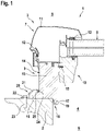
- the figure 1 shows a schematic sectional view of a building 1 which has a building shell 2 and a building closure arrangement 3 .
- the building shell 2 is in the form of a roof, in particular a flat roof.
- a recess 4 is formed in the building envelope 2, which extends completely through the building envelope 2 and to this extent connects an exterior environment 5 of the building 1 with an interior space 6 of the building 1, in particular in terms of flow technology and/or optically or lighting technology.
- the recess 4 is closed with a building closure 7 of the building closure arrangement 3, especially in terms of flow.
- the building closure 7 is in the form of a skylight which has glazing 8 , so that there is still an optical connection between the outside environment 5 and the interior 6 through the recess 4 .
- the building closure 7 has a frame designed as a window frame 9 and a casement frame 10, the casement frame 10 carrying the glazing 8 and being displaceable, in particular pivotable, with respect to the window frame 9.
- a cover plate 11 overlaps the casement 10 completely and the window frame 9 at least partially.
- the cover plate 11 extends beyond the glazing 8 and in the direction away from the glazing 8 to beyond the window frame 9.
- At least one seal 12 can be arranged between the cover plate 11 and the window frame 9 and/or the casement 10.
- At least one further seal 13 can be present between the frame 9 and the casement 10 .
- the window frame 9 has several frame members 14, only one of which is shown here.
- the frame spar 14 has a base body 15, from which a frame spar region 16 emanates and extends in the direction facing away from the glazing 8, ie outwards, particularly when viewed in section.
- the frame beam 14 On its side facing the glazing 8, the frame beam 14 has a first positive-locking device 17, which interacts positively with a second positive-locking device 80 formed by the recess 4 in order to fix the building closure 7 in the lateral direction with respect to the building shell 2.
- the first form-fitting device 17 is present as a form-fitting projection which engages in the recess 4 and rests at least temporarily, preferably permanently, against an edge 19 of the recess 4 formed by the building envelope 2 and delimiting the recess 4 .
- the fastening of the building closure 7 by means of the first form-fitting device 17 and the second form-fitting device 18 is, however, purely optional and can be omitted.
- a fastening element 20 is used for the final fastening of the building closure 7 to the building shell 2, by means of which the frame spar 14 is held on the building shell 2 in a form-fitting manner.
- the fastening element 20 has a form-fitting area 21 and a fastening area 22.
- the form-fitting area 21 overlaps the frame member 14, namely in particular the frame member area 16, at least in certain areas.
- the fastening area 22, on the other hand, is arranged next to the frame member 14 and in particular next to the frame member area 16 and rests against the building shell 2 at least in certain areas.
- the Fastening area 22 is fastened to the building shell 2 by means of at least one fastener 23, configured here as a screw.
- the fastening element 20 is designed and arranged and fastened on the building shell 2 in such a way that it holds the frame spar 14 and therefore the building closure 7 on the building shell 2 . In addition, it prevents the form-fitting devices 17 and 18 - if present - from disengaging from each other. Accordingly, the building seal 7 is reliably and permanently attached to the building shell 2 .
- the form-fitting area 21 overlaps the frame spar area 16 viewed in section, completely in the initial example shown here.
- the frame spar area 16 is arranged, viewed in section, between the form-fitting area 21 and the building shell 2 , in particular held clamped between them, preferably in a first direction.
- the form-fitting area 21 encompasses the frame spar area 16 in such a way that, viewed in section, it engages on opposite sides of the frame spar area 16 , in particular when viewed in a second direction that is different from the first direction.
- the frame spar area 16 is therefore particularly preferably arranged in the first direction between the form-fitting area 21 and the building envelope 2 and in the second direction, which differs from the first direction, between opposite sides of the form-fitting area 21.
- the second direction is angled relative to the first direction and closes with it i.e. an angle that is greater than 0° and less than 180°.
- the angle is preferably at least 70° and at most 110°, at least 80° and at most 100° or approximately or exactly 90°.
- the fastening element 20 or its form-fitting region 21 has a form-fitting projection 24 which engages in a form-fitting recess 25 in the frame member 14 in the form of a groove. This effectively prevents the building closure 7 or the frame member 14 from detaching from the fastening element 20 and consequently from the building shell 2 .
- the described configuration of the building 1 or the building closure arrangement 3 enables the building closure 7 to be reliably and permanently fixed to the building shell 2. This is also achieved with extremely simple assembly, since ultimately only the building closure 7 is arranged on the building shell 2 and secured by means of the fastening element 20 must be fixed.
- a plurality of fastening elements 20 for fastening the building closure 7 to the building shell 2 are particularly preferably provided, which are arranged on different sides of the building closure 7 and act on it.
Landscapes
- Engineering & Computer Science (AREA)
- Architecture (AREA)
- Civil Engineering (AREA)
- Structural Engineering (AREA)
- Door And Window Frames Mounted To Openings (AREA)
Applications Claiming Priority (1)
| Application Number | Priority Date | Filing Date | Title |
|---|---|---|---|
| DE102021204563.4A DE102021204563A1 (de) | 2021-05-05 | 2021-05-05 | Gebäudeverschlussanordnung zur Anordnung an einer Gebäudehülle eines Gebäudes sowie entsprechendes Gebäude |
Publications (1)
| Publication Number | Publication Date |
|---|---|
| EP4086404A1 true EP4086404A1 (fr) | 2022-11-09 |
Family
ID=81580909
Family Applications (1)
| Application Number | Title | Priority Date | Filing Date |
|---|---|---|---|
| EP22171588.1A Pending EP4086404A1 (fr) | 2021-05-05 | 2022-05-04 | Agencement de fermeture de bâtiment destiné à l'agencement sur une enveloppe de bâtiment, ainsi que bâtiment correspondant |
Country Status (2)
| Country | Link |
|---|---|
| EP (1) | EP4086404A1 (fr) |
| DE (1) | DE102021204563A1 (fr) |
Citations (6)
| Publication number | Priority date | Publication date | Assignee | Title |
|---|---|---|---|---|
| US4995208A (en) * | 1988-12-13 | 1991-02-26 | Wasco Products, Inc. | Skylight construction |
| FR2725263A1 (fr) * | 1994-10-04 | 1996-04-05 | Fuchs Dietrich Anton | Dispositif, notamment dispositif d'ancrage de distancement pour l'ajustage et la fixation de cadres |
| WO1999035355A1 (fr) * | 1997-12-19 | 1999-07-15 | Velux Industri A/S | Fenetre se montant dans une structure de toit et support de fixation s'utilisant pour le montage |
| EP1512806A1 (fr) * | 2003-08-30 | 2005-03-09 | Roto Frank Ag | Dispositif de cornière de montage pour lucarne |
| US20050086878A1 (en) * | 2003-10-24 | 2005-04-28 | Vkr Holding A/S | Flashing and mounting bracket for a skylight |
| EP2886772A1 (fr) | 2013-12-23 | 2015-06-24 | Nögel Montagetechnik Vertriebsgesellschaft mbH | Dispositif de fixation d' une fenêtre ou d'une porte dans une ouverture de paroi et un procédé pour l'installation d' une fenêtre ou d'une porte dans une ouverture de paroi |
Family Cites Families (1)
| Publication number | Priority date | Publication date | Assignee | Title |
|---|---|---|---|---|
| US8347567B2 (en) | 2011-01-07 | 2013-01-08 | Azek Building Products, Inc. | Water barrier trim |
-
2021
- 2021-05-05 DE DE102021204563.4A patent/DE102021204563A1/de active Pending
-
2022
- 2022-05-04 EP EP22171588.1A patent/EP4086404A1/fr active Pending
Patent Citations (6)
| Publication number | Priority date | Publication date | Assignee | Title |
|---|---|---|---|---|
| US4995208A (en) * | 1988-12-13 | 1991-02-26 | Wasco Products, Inc. | Skylight construction |
| FR2725263A1 (fr) * | 1994-10-04 | 1996-04-05 | Fuchs Dietrich Anton | Dispositif, notamment dispositif d'ancrage de distancement pour l'ajustage et la fixation de cadres |
| WO1999035355A1 (fr) * | 1997-12-19 | 1999-07-15 | Velux Industri A/S | Fenetre se montant dans une structure de toit et support de fixation s'utilisant pour le montage |
| EP1512806A1 (fr) * | 2003-08-30 | 2005-03-09 | Roto Frank Ag | Dispositif de cornière de montage pour lucarne |
| US20050086878A1 (en) * | 2003-10-24 | 2005-04-28 | Vkr Holding A/S | Flashing and mounting bracket for a skylight |
| EP2886772A1 (fr) | 2013-12-23 | 2015-06-24 | Nögel Montagetechnik Vertriebsgesellschaft mbH | Dispositif de fixation d' une fenêtre ou d'une porte dans une ouverture de paroi et un procédé pour l'installation d' une fenêtre ou d'une porte dans une ouverture de paroi |
Also Published As
| Publication number | Publication date |
|---|---|
| DE102021204563A1 (de) | 2022-11-10 |
Similar Documents
| Publication | Publication Date | Title |
|---|---|---|
| CH699782A2 (de) | Rahmenanschlussteil zur Befestigung an einem Rahmen. | |
| DE102009023883B4 (de) | Fassadenelement | |
| EP3835507B1 (fr) | Chevrons auxiliaires, agencement de tabatière ainsi que agencement de toit | |
| EP2792834B1 (fr) | Système comprenant un profilé de retenue pour un profilé de cadre et protection contre les chutes intégrée dans le cadre | |
| DE202007004060U1 (de) | Gebäudeabschluss in sprengwirkungshemmender Ausführung | |
| DE29705785U1 (de) | Vorrichtung zur Befestigung von Fenster- oder Türrahmen am Mauerwerk | |
| EP2610423A2 (fr) | Porte coulissante/relevable | |
| EP4299870A1 (fr) | Cadre dormant pour une porte avec cadre d'extrusion et seuil, porte avec un tel cadre dormant et procédé de fabrication de cette porte | |
| DE202011101292U1 (de) | Haltevorrichtung für Tür-, Balkon oder Fensteraustritt | |
| EP2610424A2 (fr) | Seuil de porte pour une porte coulissante/relevable | |
| EP3290611B1 (fr) | Dispositif formant toit et procédé de fabrication d'un dispositif formant toit | |
| EP3943683B1 (fr) | Cadre d'installation destiné au montage d'une fenêtre de toiture, agencement de fenêtre de toit, agencement de toit, ainsi que procédé de montage d'une fenêtre de toiture | |
| DE102004027281B4 (de) | Fensterelement mit Halteanordnung für Glasscheibe und Glasleiste | |
| DE102021204563A1 (de) | Gebäudeverschlussanordnung zur Anordnung an einer Gebäudehülle eines Gebäudes sowie entsprechendes Gebäude | |
| DE29704349U1 (de) | Hohlprofil, insbesondere aus Kunststoff, zur Bildung eines Abdeckrahmens zur Verkleidung von Holzrahmen | |
| EP1836359A1 (fr) | Façade modulaire pour batiments, joint de revetement en verre et vis | |
| DE102016218262B4 (de) | Dachfenster | |
| DE2750351A1 (de) | Profilkonstruktion | |
| DE9414631U1 (de) | Kunststoff-Hohlprofil | |
| DE19948467A1 (de) | Kasten für Rolläden oder dergleichen | |
| EP4047153A1 (fr) | Châssis du battant pour une fenêtre, procédé de fabrication d'un battant, ainsi que fenêtre dotée d'un battant | |
| EP3299569B1 (fr) | Fenêtre de toît | |
| EP3477033B1 (fr) | Système de profilé pourvu d'étrier de retenue et procédé de montage d'un système de profilé | |
| DE102023108085A1 (de) | Dachfenster und Scharniersystem für Dachfenster. | |
| DE102023205125A1 (de) | Dachfensteranordnung sowie Verfahren zum Montieren einer Dachfensteranordnung an einem Dach |
Legal Events
| Date | Code | Title | Description |
|---|---|---|---|
| PUAI | Public reference made under article 153(3) epc to a published international application that has entered the european phase |
Free format text: ORIGINAL CODE: 0009012 |
|
| STAA | Information on the status of an ep patent application or granted ep patent |
Free format text: STATUS: THE APPLICATION HAS BEEN PUBLISHED |
|
| AK | Designated contracting states |
Kind code of ref document: A1 Designated state(s): AL AT BE BG CH CY CZ DE DK EE ES FI FR GB GR HR HU IE IS IT LI LT LU LV MC MK MT NL NO PL PT RO RS SE SI SK SM TR |
|
| STAA | Information on the status of an ep patent application or granted ep patent |
Free format text: STATUS: REQUEST FOR EXAMINATION WAS MADE |
|
| 17P | Request for examination filed |
Effective date: 20230420 |
|
| RBV | Designated contracting states (corrected) |
Designated state(s): AL AT BE BG CH CY CZ DE DK EE ES FI FR GB GR HR HU IE IS IT LI LT LU LV MC MK MT NL NO PL PT RO RS SE SI SK SM TR |
|
| STAA | Information on the status of an ep patent application or granted ep patent |
Free format text: STATUS: EXAMINATION IS IN PROGRESS |
|
| 17Q | First examination report despatched |
Effective date: 20250411 |
|
| GRAP | Despatch of communication of intention to grant a patent |
Free format text: ORIGINAL CODE: EPIDOSNIGR1 |
|
| STAA | Information on the status of an ep patent application or granted ep patent |
Free format text: STATUS: GRANT OF PATENT IS INTENDED |
|
| INTG | Intention to grant announced |
Effective date: 20251204 |
|
| GRAS | Grant fee paid |
Free format text: ORIGINAL CODE: EPIDOSNIGR3 |