EP4086428A1 - Bohrlochenergiegewinnung - Google Patents
Bohrlochenergiegewinnung Download PDFInfo
- Publication number
- EP4086428A1 EP4086428A1 EP22180725.8A EP22180725A EP4086428A1 EP 4086428 A1 EP4086428 A1 EP 4086428A1 EP 22180725 A EP22180725 A EP 22180725A EP 4086428 A1 EP4086428 A1 EP 4086428A1
- Authority
- EP
- European Patent Office
- Prior art keywords
- downhole
- location
- well
- electrical energy
- metallic
- Prior art date
- Legal status (The legal status is an assumption and is not a legal conclusion. Google has not performed a legal analysis and makes no representation as to the accuracy of the status listed.)
- Granted
Links
Images





Classifications
-
- E—FIXED CONSTRUCTIONS
- E21—EARTH OR ROCK DRILLING; MINING
- E21B—EARTH OR ROCK DRILLING; OBTAINING OIL, GAS, WATER, SOLUBLE OR MELTABLE MATERIALS OR A SLURRY OF MINERALS FROM WELLS
- E21B41/00—Equipment or details not covered by groups E21B15/00 - E21B40/00
- E21B41/0085—Adaptations of electric power generating means for use in boreholes
-
- E—FIXED CONSTRUCTIONS
- E21—EARTH OR ROCK DRILLING; MINING
- E21B—EARTH OR ROCK DRILLING; OBTAINING OIL, GAS, WATER, SOLUBLE OR MELTABLE MATERIALS OR A SLURRY OF MINERALS FROM WELLS
- E21B17/00—Drilling rods or pipes; Flexible drill strings; Kellies; Drill collars; Sucker rods; Cables; Casings; Tubings
- E21B17/003—Drilling rods or pipes; Flexible drill strings; Kellies; Drill collars; Sucker rods; Cables; Casings; Tubings with electrically conducting or insulating means
-
- E—FIXED CONSTRUCTIONS
- E21—EARTH OR ROCK DRILLING; MINING
- E21B—EARTH OR ROCK DRILLING; OBTAINING OIL, GAS, WATER, SOLUBLE OR MELTABLE MATERIALS OR A SLURRY OF MINERALS FROM WELLS
- E21B34/00—Valve arrangements for boreholes or wells
- E21B34/06—Valve arrangements for boreholes or wells in wells
- E21B34/066—Valve arrangements for boreholes or wells in wells electrically actuated
-
- E—FIXED CONSTRUCTIONS
- E21—EARTH OR ROCK DRILLING; MINING
- E21B—EARTH OR ROCK DRILLING; OBTAINING OIL, GAS, WATER, SOLUBLE OR MELTABLE MATERIALS OR A SLURRY OF MINERALS FROM WELLS
- E21B41/00—Equipment or details not covered by groups E21B15/00 - E21B40/00
- E21B41/02—Equipment or details not covered by groups E21B15/00 - E21B40/00 in situ inhibition of corrosion in boreholes or wells
-
- E—FIXED CONSTRUCTIONS
- E21—EARTH OR ROCK DRILLING; MINING
- E21B—EARTH OR ROCK DRILLING; OBTAINING OIL, GAS, WATER, SOLUBLE OR MELTABLE MATERIALS OR A SLURRY OF MINERALS FROM WELLS
- E21B47/00—Survey of boreholes or wells
- E21B47/12—Means for transmitting measuring-signals or control signals from the well to the surface, or from the surface to the well, e.g. for logging while drilling
Definitions
- This invention relates to downhole energy harvesting.
- it relates to methods and systems for powering a downhole device in a well installation having metallic structure provided with cathodic protection.
- the invention also relates to methods and systems incorporating energy harvesting methods and systems as well as apparatus for use in such methods and systems.
- the harvesting module may be arranged to harvest electrical energy from dc currents.
- Upper communication means may be provided at an out of bore hole location including a detector for detecting changes in the current, say the cathodic protection current, flowing in the metallic structure and hence allowing extraction of data encoded by modulation of the load at the harvesting module.
- the detector may be arranged to detect the potential of the metallic structure relative to a reference or to detect the potential seen across; or current seen by, a power supply used to apply an impressed cathodic protection current to the metallic structure.
- the potential difference between the spaced contacts is less than 1 volt, preferably less than 0.5 volts, more preferably less than 0.1 volts.
- the pressure sensor may be arranged for monitoring the reservoir pressure of the well.
- the communications repeater and/or the harvesting module may be provided in an annulus - for example the "B" annulus or the "C” annulus or another annulus.
- the downhole communication means may be arranged for transmitting data by varying the load seen between the connections at the spaced locations.
- the cross sectional area of the conductive core, or cores, of the cable used to supply the electrical power further downhole may be smaller than that of cable used to connect the harvesting module to the downhole structure for harvesting the power.
- the potential difference between the spaced contacts may be less than 1 volt, preferably less than 0.5 volts, more preferably less than 0.1 volts.
- a downhole data communication system for use in a well installation having metallic structure provided with a cathodic protection system such that there is an electrical circuit comprising the metallic structure and an earth return around which an electrical current flows as a result of the cathodic protection system, the system comprising downhole data communication apparatus comprising:
- the system or apparatus may comprise a pressure sensor arranged for monitoring the pressure in an enclosed annulus of the well.
- the harvesting module may comprise variable impedance means for varying the load seen between the two connections.
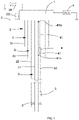
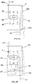
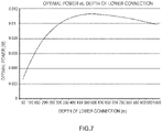
- the central unit 46 controls the operation of the dc to dc converter 44 so as to optimise the load which it presents to the current seen by the harvesting module 4 due to the cathodic protection currents in order to maximise the energy which may be harvested and used or stored in the charge storage means 45.
- the central unit may be arranged to selectively use and/or deliver harvested energy directly when appropriate, and store energy and extract stored energy when appropriate.
- microprocessor driven central unit 46 may be replaced by alternative electronics including say an analogue feedback circuit, or a state machine or even a fixed harvesting load based on modelling for the particular installation.
- an appropriate sensor may be provided at the same location as the harvesting module 4.
- the battery 211 may be a primary (one shot) battery, or may be a rechargeable battery provided it is charged at the time of installation. Where the battery is a re-chargeable battery, in some implementations the power supply unit 210 may be arranged to store energy in it when available, alternatively it may be more convenient to provide a separate energy storage means (which might include a rechargeable battery).
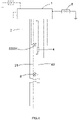
- Figure 4 schematically shows a well installation including a remotely controlled valve and a power delivery system of the same general type as described above.
- control signals for the second subsurface safety valve 8 may be transmitted by the upper communications unit 6 via the metallic structure of the well 1, 2 for detection by the harvesting module 4 and onwards transmission to the subsurface safety valve 8.
- the valve 8 may be caused to operate in a fail safe mode such that the valve will close in the absence of power and/or control signals.
- the valve 8 and harvesting module might be provided as part of a common downhole tool 4a.
- power for closing the valve may come from another source, with the downhole power delivery system supplying power for controlling operation and/or operating a trigger mechanism.
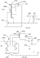
- the means of insulating the two runs of metallic structure 22, 23 from one another comprise an insulating coating 91 provided on the outer surface of the first casing 22 and a plurality of insulating centralisers 92 provided on the first casing 22 to keep this separated from the second casing 23.
- this insulation 91 and these centralisers 92 will be provided over a length of the first casing 22 of at least 100 metres and more likely 300 to 500 metres.
- insulating spacers may be mounted on the outer run of metallic structure forming the annulus.
- the insulation need not be entirely continuous to provide a useful effect.
- the creation of a different path to earth is the aim.
- the insulation may be provided over 100m, it may not be continuous, or provide continuous insulation over this distance.
- FIG. 4 Whilst the arrangement in Figure 4 shows the provision of an additional subsurface safety valve 8, in other circumstances a different type of (possibly remotely operated) valve or component may be provided.
- an arrangement of the type shown in Figure 4 may be used with an annulus vent valve provided in a well to allow controlled fluid communication or venting between one annulus and another or between an annulus and the bore.
- the valve could comprise a gas lift injection valve for allowing gas into the bore of production tubing from the A annulus.
- the valve may be a packer, a through packer valve or a packer by-pass valve. Again for allowing venting of a particular annulus under control from the surface.
- the present techniques may be used for communication with and/or control of a tool supported by a wireline/slick line or attached to coiled tubing in the production tubing 21. That is to say, such a tool may be arranged to apply signals to and/or pick up signals from the tubing which signals pass through the repeater 7.
- the well installation includes monitoring apparatus in the same way as Figure 1 .
- a harvesting module 4 connected via cables 41 to a pair of spaced locations 41a and 41b.
- a first of the locations 41a is on the production tubing 21 and thus a first of the cables 41 is connected to the production tubing whilst the second of the spaced locations 41b is on the casing 22.
- insulation 91 is provided on the production tubing 21 in the region of the second connection 41b and extends axially either side of this.
- one connection might be to the formation rather than to the metallic structure.
- all of the apparatus of the power delivery system could be provided outside of the casing - i.e. between the casing and formation. This will generally be undesirable from a risk/difficulty in installation point of view, but is a possibility.
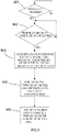
- step 901 it is determined whether there is sufficient power to power the processor in the central unit 46. If not the process stays at this step until there is sufficient power.
- Different wireless signals may be used in the same well for communications going from the well towards the surface, and for communications going from the surface into the well.
- Acoustic signals and communications may include Frequency Shift Keying (FSK) and/or Phase Shift Keying (PSK) modulation methods, and/or more advanced derivatives of these methods, such as Quadrature Phase Shift Keying (QPSK) or Quadrature Amplitude Modulation (QAM), and preferably incorporating Spread Spectrum Techniques. Typically they are adapted to automatically tune acoustic signalling frequencies and methods to suit well conditions.
- FSK Frequency Shift Keying
- PSK Phase Shift Keying
- QPSK Quadrature Phase Shift Keying
- QAM Quadrature Amplitude Modulation
- Spread Spectrum Techniques Typically they are adapted to automatically tune acoustic signalling frequencies and methods to suit well conditions.
- elongate member for the purposes of EM transmission, this could also mean any elongate electrical conductor including: liner; casing; tubing or tubular; coil tubing; sucker rod; wireline; drill pipe; slickline or coiled rod.
- any preceding paragraph means any of the preceding numbered paragraphs below.
- Paragraph 9 A downhole electrical energy harvesting system according to any preceding Paragraph wherein the electrical connection to the metallic structure at the first location is made to one of: casing, liner, tubing, coiled tubing, sucker rod.
- Paragraph 24 A downhole electrical energy harvesting system according to any preceding Paragraph, wherein the current flowing in the elongate member is supplied from one or more sacrificial anodes.
Landscapes
- Engineering & Computer Science (AREA)
- Geology (AREA)
- Mining & Mineral Resources (AREA)
- Life Sciences & Earth Sciences (AREA)
- Physics & Mathematics (AREA)
- General Life Sciences & Earth Sciences (AREA)
- Fluid Mechanics (AREA)
- Environmental & Geological Engineering (AREA)
- Geochemistry & Mineralogy (AREA)
- Geophysics (AREA)
- Remote Sensing (AREA)
- Mechanical Engineering (AREA)
- Prevention Of Electric Corrosion (AREA)
- Laying Of Electric Cables Or Lines Outside (AREA)
- Cable Transmission Systems, Equalization Of Radio And Reduction Of Echo (AREA)
Priority Applications (1)
| Application Number | Priority Date | Filing Date | Title |
|---|---|---|---|
| EP22180725.8A EP4086428B1 (de) | 2016-12-30 | 2016-12-30 | Bohrlochenergiegewinnung |
Applications Claiming Priority (3)
| Application Number | Priority Date | Filing Date | Title |
|---|---|---|---|
| PCT/GB2016/054094 WO2018122544A1 (en) | 2016-12-30 | 2016-12-30 | Downhole energy harvesting |
| EP22180725.8A EP4086428B1 (de) | 2016-12-30 | 2016-12-30 | Bohrlochenergiegewinnung |
| EP16822512.6A EP3563028B1 (de) | 2016-12-30 | 2016-12-30 | Bohrlochenergiegewinnung |
Related Parent Applications (2)
| Application Number | Title | Priority Date | Filing Date |
|---|---|---|---|
| EP16822512.6A Division EP3563028B1 (de) | 2016-12-30 | 2016-12-30 | Bohrlochenergiegewinnung |
| EP16822512.6A Division-Into EP3563028B1 (de) | 2016-12-30 | 2016-12-30 | Bohrlochenergiegewinnung |
Publications (2)
| Publication Number | Publication Date |
|---|---|
| EP4086428A1 true EP4086428A1 (de) | 2022-11-09 |
| EP4086428B1 EP4086428B1 (de) | 2024-10-16 |
Family
ID=57737753
Family Applications (2)
| Application Number | Title | Priority Date | Filing Date |
|---|---|---|---|
| EP22180725.8A Active EP4086428B1 (de) | 2016-12-30 | 2016-12-30 | Bohrlochenergiegewinnung |
| EP16822512.6A Active EP3563028B1 (de) | 2016-12-30 | 2016-12-30 | Bohrlochenergiegewinnung |
Family Applications After (1)
| Application Number | Title | Priority Date | Filing Date |
|---|---|---|---|
| EP16822512.6A Active EP3563028B1 (de) | 2016-12-30 | 2016-12-30 | Bohrlochenergiegewinnung |
Country Status (3)
| Country | Link |
|---|---|
| US (1) | US11072999B2 (de) |
| EP (2) | EP4086428B1 (de) |
| WO (1) | WO2018122544A1 (de) |
Families Citing this family (4)
| Publication number | Priority date | Publication date | Assignee | Title |
|---|---|---|---|---|
| EP3563032B1 (de) * | 2016-12-30 | 2021-11-10 | Metrol Technology Ltd | Bohrlochenergiegewinnung |
| CN110382817A (zh) * | 2016-12-30 | 2019-10-25 | 美德龙技术有限公司 | 井下能量收集 |
| WO2018178607A1 (en) * | 2017-03-31 | 2018-10-04 | Metrol Technology Ltd | Monitoring well installations |
| US11506027B1 (en) * | 2020-12-02 | 2022-11-22 | Streamline Innovations, Inc. | Well-bore energy storage unit |
Citations (6)
| Publication number | Priority date | Publication date | Assignee | Title |
|---|---|---|---|---|
| US5831549A (en) | 1997-05-27 | 1998-11-03 | Gearhart; Marvin | Telemetry system involving gigahertz transmission in a gas filled tubular waveguide |
| US20090078585A1 (en) * | 2006-04-26 | 2009-03-26 | Sicco Dwars | Using an impressed current cathodic protection system to power electrical appliances |
| GB2461065A (en) * | 2008-06-18 | 2009-12-23 | Expro North Sea Ltd | Fail safe safety valve |
| US20140218208A1 (en) * | 2011-06-27 | 2014-08-07 | Expro North Sea Limited | Downhole signalling systems and methods |
| US20140320301A1 (en) * | 2011-11-11 | 2014-10-30 | Expro North Sea Limited | Downhole structure sections |
| US20150252625A1 (en) * | 2012-11-29 | 2015-09-10 | Chevron U.S.A. Inc. | Transmitting Power Within A Wellbore |
Family Cites Families (22)
| Publication number | Priority date | Publication date | Assignee | Title |
|---|---|---|---|---|
| US4228399A (en) | 1978-02-27 | 1980-10-14 | Harco Corporation | Offshore pipeline electrical survey method and apparatus |
| EP0924711A3 (de) | 1997-12-19 | 1999-07-07 | Camco International Inc. | Elektrisches mehradriges Kabel |
| GB9801010D0 (en) | 1998-01-16 | 1998-03-18 | Flight Refueling Ltd | Data transmission systems |
| US6662875B2 (en) | 2000-01-24 | 2003-12-16 | Shell Oil Company | Induction choke for power distribution in piping structure |
| US7322410B2 (en) | 2001-03-02 | 2008-01-29 | Shell Oil Company | Controllable production well packer |
| BRPI0411292A (pt) | 2003-06-13 | 2006-08-01 | Shell Int Research | sistema e método para transmitir energia elétrica para o interior de um furo de sondagem e furo de sondagem estendendo-se para o interior de uma formação geológica |
| US7180825B2 (en) | 2004-06-29 | 2007-02-20 | Halliburton Energy Services, Inc. | Downhole telemetry system for wired tubing |
| NO324328B1 (no) | 2005-07-01 | 2007-09-24 | Statoil Asa | System for elektrisk kraft- og signaloverforing i en produksjonsbronn |
| GB2448928B (en) | 2007-05-04 | 2009-12-09 | Dynamic Dinosaurs Bv | Power transmission system for use with downhole equipment |
| EP2291688B1 (de) * | 2008-06-18 | 2011-11-23 | Expro North Sea Limited | Erzeugung von elektrischer impedanz in einer förderleitung |
| US8536528B2 (en) | 2008-12-12 | 2013-09-17 | Baker Hughes Incorporated | System and method for downhole voltage generation |
| GB2475731B (en) | 2009-11-30 | 2014-01-22 | Vetco Gray Controls Ltd | Cathodic protection monitoring |
| GB201012175D0 (en) | 2010-07-20 | 2010-09-01 | Metrol Tech Ltd | Procedure and mechanisms |
| US8298382B2 (en) | 2010-12-15 | 2012-10-30 | Abriox Limited | Apparatus for use with metallic structures |
| GB2486685A (en) | 2010-12-20 | 2012-06-27 | Expro North Sea Ltd | Electrical power and/or signal transmission through a metallic wall |
| EP2607617A1 (de) | 2011-12-21 | 2013-06-26 | Siemens Aktiengesellschaft | Förderlochanordnung |
| US9091144B2 (en) | 2012-03-23 | 2015-07-28 | Baker Hughes Incorporated | Environmentally powered transmitter for location identification of wellbores |
| US8779932B2 (en) | 2012-08-16 | 2014-07-15 | Vetco Gray U.K. Limited | Power supply and voltage multiplication for submerged subsea systems based on cathodic protection system |
| WO2016010517A1 (en) | 2014-07-15 | 2016-01-21 | Halliburton Energy Services, Inc. | Acoustic calipering and analysis of annulus materials |
| GB2573848A (en) * | 2016-09-19 | 2019-11-20 | Halliburton Energy Services Inc | Powering downhole components in subsurface formations behind casing |
| US10113410B2 (en) | 2016-09-30 | 2018-10-30 | Onesubsea Ip Uk Limited | Systems and methods for wirelessly monitoring well integrity |
| CN110382817A (zh) * | 2016-12-30 | 2019-10-25 | 美德龙技术有限公司 | 井下能量收集 |
-
2016
- 2016-12-30 EP EP22180725.8A patent/EP4086428B1/de active Active
- 2016-12-30 US US16/473,808 patent/US11072999B2/en active Active
- 2016-12-30 WO PCT/GB2016/054094 patent/WO2018122544A1/en not_active Ceased
- 2016-12-30 EP EP16822512.6A patent/EP3563028B1/de active Active
Patent Citations (6)
| Publication number | Priority date | Publication date | Assignee | Title |
|---|---|---|---|---|
| US5831549A (en) | 1997-05-27 | 1998-11-03 | Gearhart; Marvin | Telemetry system involving gigahertz transmission in a gas filled tubular waveguide |
| US20090078585A1 (en) * | 2006-04-26 | 2009-03-26 | Sicco Dwars | Using an impressed current cathodic protection system to power electrical appliances |
| GB2461065A (en) * | 2008-06-18 | 2009-12-23 | Expro North Sea Ltd | Fail safe safety valve |
| US20140218208A1 (en) * | 2011-06-27 | 2014-08-07 | Expro North Sea Limited | Downhole signalling systems and methods |
| US20140320301A1 (en) * | 2011-11-11 | 2014-10-30 | Expro North Sea Limited | Downhole structure sections |
| US20150252625A1 (en) * | 2012-11-29 | 2015-09-10 | Chevron U.S.A. Inc. | Transmitting Power Within A Wellbore |
Also Published As
| Publication number | Publication date |
|---|---|
| WO2018122544A1 (en) | 2018-07-05 |
| US20190323322A1 (en) | 2019-10-24 |
| EP4086428B1 (de) | 2024-10-16 |
| US11072999B2 (en) | 2021-07-27 |
| EP3563028B1 (de) | 2022-08-17 |
| EP3563028A1 (de) | 2019-11-06 |
Similar Documents
| Publication | Publication Date | Title |
|---|---|---|
| US11795786B2 (en) | Downhole energy harvesting | |
| US20230019444A1 (en) | Downhole energy harvesting | |
| AU2016434207B2 (en) | Downhole energy harvesting | |
| AU2016434681B2 (en) | Downhole communication | |
| EP3563028B1 (de) | Bohrlochenergiegewinnung | |
| CA3047618C (en) | Downhole communication | |
| OA19348A (en) | Downhole Energy Harvesting | |
| EA043424B1 (ru) | Внутрискважинный сбор энергии |
Legal Events
| Date | Code | Title | Description |
|---|---|---|---|
| PUAI | Public reference made under article 153(3) epc to a published international application that has entered the european phase |
Free format text: ORIGINAL CODE: 0009012 |
|
| STAA | Information on the status of an ep patent application or granted ep patent |
Free format text: STATUS: THE APPLICATION HAS BEEN PUBLISHED |
|
| AC | Divisional application: reference to earlier application |
Ref document number: 3563028 Country of ref document: EP Kind code of ref document: P |
|
| AK | Designated contracting states |
Kind code of ref document: A1 Designated state(s): AL AT BE BG CH CY CZ DE DK EE ES FI FR GB GR HR HU IE IS IT LI LT LU LV MC MK MT NL NO PL PT RO RS SE SI SK SM TR |
|
| STAA | Information on the status of an ep patent application or granted ep patent |
Free format text: STATUS: REQUEST FOR EXAMINATION WAS MADE |
|
| 17P | Request for examination filed |
Effective date: 20230505 |
|
| RBV | Designated contracting states (corrected) |
Designated state(s): AL AT BE BG CH CY CZ DE DK EE ES FI FR GB GR HR HU IE IS IT LI LT LU LV MC MK MT NL NO PL PT RO RS SE SI SK SM TR |
|
| STAA | Information on the status of an ep patent application or granted ep patent |
Free format text: STATUS: EXAMINATION IS IN PROGRESS |
|
| 17Q | First examination report despatched |
Effective date: 20231215 |
|
| GRAP | Despatch of communication of intention to grant a patent |
Free format text: ORIGINAL CODE: EPIDOSNIGR1 |
|
| STAA | Information on the status of an ep patent application or granted ep patent |
Free format text: STATUS: GRANT OF PATENT IS INTENDED |
|
| INTG | Intention to grant announced |
Effective date: 20240513 |
|
| GRAS | Grant fee paid |
Free format text: ORIGINAL CODE: EPIDOSNIGR3 |
|
| GRAA | (expected) grant |
Free format text: ORIGINAL CODE: 0009210 |
|
| STAA | Information on the status of an ep patent application or granted ep patent |
Free format text: STATUS: THE PATENT HAS BEEN GRANTED |
|
| P01 | Opt-out of the competence of the unified patent court (upc) registered |
Free format text: CASE NUMBER: APP_46899/2024 Effective date: 20240813 |
|
| AC | Divisional application: reference to earlier application |
Ref document number: 3563028 Country of ref document: EP Kind code of ref document: P |
|
| AK | Designated contracting states |
Kind code of ref document: B1 Designated state(s): AL AT BE BG CH CY CZ DE DK EE ES FI FR GB GR HR HU IE IS IT LI LT LU LV MC MK MT NL NO PL PT RO RS SE SI SK SM TR |
|
| REG | Reference to a national code |
Ref country code: GB Ref legal event code: FG4D |
|
| REG | Reference to a national code |
Ref country code: CH Ref legal event code: EP |
|
| REG | Reference to a national code |
Ref country code: IE Ref legal event code: FG4D |
|
| REG | Reference to a national code |
Ref country code: DE Ref legal event code: R096 Ref document number: 602016089918 Country of ref document: DE |
|
| REG | Reference to a national code |
Ref country code: LT Ref legal event code: MG9D |
|
| REG | Reference to a national code |
Ref country code: NL Ref legal event code: MP Effective date: 20241016 |
|
| REG | Reference to a national code |
Ref country code: AT Ref legal event code: MK05 Ref document number: 1733053 Country of ref document: AT Kind code of ref document: T Effective date: 20241016 |
|
| PG25 | Lapsed in a contracting state [announced via postgrant information from national office to epo] |
Ref country code: NL Free format text: LAPSE BECAUSE OF FAILURE TO SUBMIT A TRANSLATION OF THE DESCRIPTION OR TO PAY THE FEE WITHIN THE PRESCRIBED TIME-LIMIT Effective date: 20241016 |
|
| PG25 | Lapsed in a contracting state [announced via postgrant information from national office to epo] |
Ref country code: NL Free format text: LAPSE BECAUSE OF FAILURE TO SUBMIT A TRANSLATION OF THE DESCRIPTION OR TO PAY THE FEE WITHIN THE PRESCRIBED TIME-LIMIT Effective date: 20241016 |
|
| PG25 | Lapsed in a contracting state [announced via postgrant information from national office to epo] |
Ref country code: HR Free format text: LAPSE BECAUSE OF FAILURE TO SUBMIT A TRANSLATION OF THE DESCRIPTION OR TO PAY THE FEE WITHIN THE PRESCRIBED TIME-LIMIT Effective date: 20241016 Ref country code: PT Free format text: LAPSE BECAUSE OF FAILURE TO SUBMIT A TRANSLATION OF THE DESCRIPTION OR TO PAY THE FEE WITHIN THE PRESCRIBED TIME-LIMIT Effective date: 20250217 Ref country code: IS Free format text: LAPSE BECAUSE OF FAILURE TO SUBMIT A TRANSLATION OF THE DESCRIPTION OR TO PAY THE FEE WITHIN THE PRESCRIBED TIME-LIMIT Effective date: 20250216 |
|
| PG25 | Lapsed in a contracting state [announced via postgrant information from national office to epo] |
Ref country code: FI Free format text: LAPSE BECAUSE OF FAILURE TO SUBMIT A TRANSLATION OF THE DESCRIPTION OR TO PAY THE FEE WITHIN THE PRESCRIBED TIME-LIMIT Effective date: 20241016 |
|
| PG25 | Lapsed in a contracting state [announced via postgrant information from national office to epo] |
Ref country code: BG Free format text: LAPSE BECAUSE OF FAILURE TO SUBMIT A TRANSLATION OF THE DESCRIPTION OR TO PAY THE FEE WITHIN THE PRESCRIBED TIME-LIMIT Effective date: 20241016 |
|
| PG25 | Lapsed in a contracting state [announced via postgrant information from national office to epo] |
Ref country code: ES Free format text: LAPSE BECAUSE OF FAILURE TO SUBMIT A TRANSLATION OF THE DESCRIPTION OR TO PAY THE FEE WITHIN THE PRESCRIBED TIME-LIMIT Effective date: 20241016 |
|
| PG25 | Lapsed in a contracting state [announced via postgrant information from national office to epo] |
Ref country code: LV Free format text: LAPSE BECAUSE OF FAILURE TO SUBMIT A TRANSLATION OF THE DESCRIPTION OR TO PAY THE FEE WITHIN THE PRESCRIBED TIME-LIMIT Effective date: 20241016 Ref country code: GR Free format text: LAPSE BECAUSE OF FAILURE TO SUBMIT A TRANSLATION OF THE DESCRIPTION OR TO PAY THE FEE WITHIN THE PRESCRIBED TIME-LIMIT Effective date: 20250117 Ref country code: AT Free format text: LAPSE BECAUSE OF FAILURE TO SUBMIT A TRANSLATION OF THE DESCRIPTION OR TO PAY THE FEE WITHIN THE PRESCRIBED TIME-LIMIT Effective date: 20241016 |
|
| PG25 | Lapsed in a contracting state [announced via postgrant information from national office to epo] |
Ref country code: PL Free format text: LAPSE BECAUSE OF FAILURE TO SUBMIT A TRANSLATION OF THE DESCRIPTION OR TO PAY THE FEE WITHIN THE PRESCRIBED TIME-LIMIT Effective date: 20241016 |
|
| PG25 | Lapsed in a contracting state [announced via postgrant information from national office to epo] |
Ref country code: RS Free format text: LAPSE BECAUSE OF FAILURE TO SUBMIT A TRANSLATION OF THE DESCRIPTION OR TO PAY THE FEE WITHIN THE PRESCRIBED TIME-LIMIT Effective date: 20250116 |
|
| REG | Reference to a national code |
Ref country code: DE Ref legal event code: R119 Ref document number: 602016089918 Country of ref document: DE |
|
| PG25 | Lapsed in a contracting state [announced via postgrant information from national office to epo] |
Ref country code: SM Free format text: LAPSE BECAUSE OF FAILURE TO SUBMIT A TRANSLATION OF THE DESCRIPTION OR TO PAY THE FEE WITHIN THE PRESCRIBED TIME-LIMIT Effective date: 20241016 |
|
| PG25 | Lapsed in a contracting state [announced via postgrant information from national office to epo] |
Ref country code: MC Free format text: LAPSE BECAUSE OF FAILURE TO SUBMIT A TRANSLATION OF THE DESCRIPTION OR TO PAY THE FEE WITHIN THE PRESCRIBED TIME-LIMIT Effective date: 20241016 |
|
| PG25 | Lapsed in a contracting state [announced via postgrant information from national office to epo] |
Ref country code: DK Free format text: LAPSE BECAUSE OF FAILURE TO SUBMIT A TRANSLATION OF THE DESCRIPTION OR TO PAY THE FEE WITHIN THE PRESCRIBED TIME-LIMIT Effective date: 20241016 |
|
| PG25 | Lapsed in a contracting state [announced via postgrant information from national office to epo] |
Ref country code: EE Free format text: LAPSE BECAUSE OF FAILURE TO SUBMIT A TRANSLATION OF THE DESCRIPTION OR TO PAY THE FEE WITHIN THE PRESCRIBED TIME-LIMIT Effective date: 20241016 |
|
| PG25 | Lapsed in a contracting state [announced via postgrant information from national office to epo] |
Ref country code: RO Free format text: LAPSE BECAUSE OF FAILURE TO SUBMIT A TRANSLATION OF THE DESCRIPTION OR TO PAY THE FEE WITHIN THE PRESCRIBED TIME-LIMIT Effective date: 20241016 |
|
| PG25 | Lapsed in a contracting state [announced via postgrant information from national office to epo] |
Ref country code: SK Free format text: LAPSE BECAUSE OF FAILURE TO SUBMIT A TRANSLATION OF THE DESCRIPTION OR TO PAY THE FEE WITHIN THE PRESCRIBED TIME-LIMIT Effective date: 20241016 |
|
| PG25 | Lapsed in a contracting state [announced via postgrant information from national office to epo] |
Ref country code: CZ Free format text: LAPSE BECAUSE OF FAILURE TO SUBMIT A TRANSLATION OF THE DESCRIPTION OR TO PAY THE FEE WITHIN THE PRESCRIBED TIME-LIMIT Effective date: 20241016 |
|
| PG25 | Lapsed in a contracting state [announced via postgrant information from national office to epo] |
Ref country code: IT Free format text: LAPSE BECAUSE OF FAILURE TO SUBMIT A TRANSLATION OF THE DESCRIPTION OR TO PAY THE FEE WITHIN THE PRESCRIBED TIME-LIMIT Effective date: 20241016 |
|
| REG | Reference to a national code |
Ref country code: CH Ref legal event code: PL |
|
| PG25 | Lapsed in a contracting state [announced via postgrant information from national office to epo] |
Ref country code: LU Free format text: LAPSE BECAUSE OF NON-PAYMENT OF DUE FEES Effective date: 20241230 |
|
| PLBE | No opposition filed within time limit |
Free format text: ORIGINAL CODE: 0009261 |
|
| STAA | Information on the status of an ep patent application or granted ep patent |
Free format text: STATUS: NO OPPOSITION FILED WITHIN TIME LIMIT |
|
| PG25 | Lapsed in a contracting state [announced via postgrant information from national office to epo] |
Ref country code: SE Free format text: LAPSE BECAUSE OF FAILURE TO SUBMIT A TRANSLATION OF THE DESCRIPTION OR TO PAY THE FEE WITHIN THE PRESCRIBED TIME-LIMIT Effective date: 20241016 |
|
| 26N | No opposition filed |
Effective date: 20250717 |
|
| REG | Reference to a national code |
Ref country code: BE Ref legal event code: MM Effective date: 20241231 |
|
| PG25 | Lapsed in a contracting state [announced via postgrant information from national office to epo] |
Ref country code: DE Free format text: LAPSE BECAUSE OF NON-PAYMENT OF DUE FEES Effective date: 20250701 |
|
| PG25 | Lapsed in a contracting state [announced via postgrant information from national office to epo] |
Ref country code: BE Free format text: LAPSE BECAUSE OF NON-PAYMENT OF DUE FEES Effective date: 20241231 |
|
| PG25 | Lapsed in a contracting state [announced via postgrant information from national office to epo] |
Ref country code: FR Free format text: LAPSE BECAUSE OF NON-PAYMENT OF DUE FEES Effective date: 20241231 |
|
| PG25 | Lapsed in a contracting state [announced via postgrant information from national office to epo] |
Ref country code: CH Free format text: LAPSE BECAUSE OF NON-PAYMENT OF DUE FEES Effective date: 20241231 |
|
| PG25 | Lapsed in a contracting state [announced via postgrant information from national office to epo] |
Ref country code: IE Free format text: LAPSE BECAUSE OF NON-PAYMENT OF DUE FEES Effective date: 20241230 |
|
| PGFP | Annual fee paid to national office [announced via postgrant information from national office to epo] |
Ref country code: GB Payment date: 20251229 Year of fee payment: 10 |
|
| PGFP | Annual fee paid to national office [announced via postgrant information from national office to epo] |
Ref country code: NO Payment date: 20251230 Year of fee payment: 10 |