EP4086432A1 - Leitschaufel mit stiftbefestigung und drehsicherem leitblech - Google Patents
Leitschaufel mit stiftbefestigung und drehsicherem leitblech Download PDFInfo
- Publication number
- EP4086432A1 EP4086432A1 EP22164835.5A EP22164835A EP4086432A1 EP 4086432 A1 EP4086432 A1 EP 4086432A1 EP 22164835 A EP22164835 A EP 22164835A EP 4086432 A1 EP4086432 A1 EP 4086432A1
- Authority
- EP
- European Patent Office
- Prior art keywords
- spar
- baffle
- support platform
- platform
- pin
- Prior art date
- Legal status (The legal status is an assumption and is not a legal conclusion. Google has not performed a legal analysis and makes no representation as to the accuracy of the status listed.)
- Granted
Links
Images



Classifications
-
- F—MECHANICAL ENGINEERING; LIGHTING; HEATING; WEAPONS; BLASTING
- F01—MACHINES OR ENGINES IN GENERAL; ENGINE PLANTS IN GENERAL; STEAM ENGINES
- F01D—NON-POSITIVE DISPLACEMENT MACHINES OR ENGINES, e.g. STEAM TURBINES
- F01D9/00—Stators
- F01D9/02—Nozzles; Nozzle boxes; Stator blades; Guide conduits, e.g. individual nozzles
- F01D9/04—Nozzles; Nozzle boxes; Stator blades; Guide conduits, e.g. individual nozzles forming ring or sector
- F01D9/041—Nozzles; Nozzle boxes; Stator blades; Guide conduits, e.g. individual nozzles forming ring or sector using blades
-
- F—MECHANICAL ENGINEERING; LIGHTING; HEATING; WEAPONS; BLASTING
- F01—MACHINES OR ENGINES IN GENERAL; ENGINE PLANTS IN GENERAL; STEAM ENGINES
- F01D—NON-POSITIVE DISPLACEMENT MACHINES OR ENGINES, e.g. STEAM TURBINES
- F01D25/00—Component parts, details, or accessories, not provided for in, or of interest apart from, other groups
- F01D25/24—Casings; Casing parts, e.g. diaphragms, casing fastenings
- F01D25/246—Fastening of diaphragms or stator-rings
-
- F—MECHANICAL ENGINEERING; LIGHTING; HEATING; WEAPONS; BLASTING
- F01—MACHINES OR ENGINES IN GENERAL; ENGINE PLANTS IN GENERAL; STEAM ENGINES
- F01D—NON-POSITIVE DISPLACEMENT MACHINES OR ENGINES, e.g. STEAM TURBINES
- F01D5/00—Blades; Blade-carrying members; Heating, heat-insulating, cooling or antivibration means on the blades or the members
- F01D5/12—Blades
- F01D5/14—Form or construction
- F01D5/147—Construction, i.e. structural features, e.g. of weight-saving hollow blades
-
- F—MECHANICAL ENGINEERING; LIGHTING; HEATING; WEAPONS; BLASTING
- F01—MACHINES OR ENGINES IN GENERAL; ENGINE PLANTS IN GENERAL; STEAM ENGINES
- F01D—NON-POSITIVE DISPLACEMENT MACHINES OR ENGINES, e.g. STEAM TURBINES
- F01D5/00—Blades; Blade-carrying members; Heating, heat-insulating, cooling or antivibration means on the blades or the members
- F01D5/12—Blades
- F01D5/14—Form or construction
- F01D5/18—Hollow blades, i.e. blades with cooling or heating channels or cavities; Heating, heat-insulating or cooling means on blades
- F01D5/187—Convection cooling
- F01D5/188—Convection cooling with an insert in the blade cavity to guide the cooling fluid, e.g. forming a separation wall
-
- F—MECHANICAL ENGINEERING; LIGHTING; HEATING; WEAPONS; BLASTING
- F01—MACHINES OR ENGINES IN GENERAL; ENGINE PLANTS IN GENERAL; STEAM ENGINES
- F01D—NON-POSITIVE DISPLACEMENT MACHINES OR ENGINES, e.g. STEAM TURBINES
- F01D5/00—Blades; Blade-carrying members; Heating, heat-insulating, cooling or antivibration means on the blades or the members
- F01D5/12—Blades
- F01D5/28—Selecting particular materials; Particular measures relating thereto; Measures against erosion or corrosion
- F01D5/282—Selecting composite materials, e.g. blades with reinforcing filaments
-
- F—MECHANICAL ENGINEERING; LIGHTING; HEATING; WEAPONS; BLASTING
- F01—MACHINES OR ENGINES IN GENERAL; ENGINE PLANTS IN GENERAL; STEAM ENGINES
- F01D—NON-POSITIVE DISPLACEMENT MACHINES OR ENGINES, e.g. STEAM TURBINES
- F01D5/00—Blades; Blade-carrying members; Heating, heat-insulating, cooling or antivibration means on the blades or the members
- F01D5/12—Blades
- F01D5/28—Selecting particular materials; Particular measures relating thereto; Measures against erosion or corrosion
- F01D5/284—Selection of ceramic materials
-
- F—MECHANICAL ENGINEERING; LIGHTING; HEATING; WEAPONS; BLASTING
- F01—MACHINES OR ENGINES IN GENERAL; ENGINE PLANTS IN GENERAL; STEAM ENGINES
- F01D—NON-POSITIVE DISPLACEMENT MACHINES OR ENGINES, e.g. STEAM TURBINES
- F01D9/00—Stators
- F01D9/02—Nozzles; Nozzle boxes; Stator blades; Guide conduits, e.g. individual nozzles
- F01D9/04—Nozzles; Nozzle boxes; Stator blades; Guide conduits, e.g. individual nozzles forming ring or sector
- F01D9/042—Nozzles; Nozzle boxes; Stator blades; Guide conduits, e.g. individual nozzles forming ring or sector fixing blades to stators
-
- F—MECHANICAL ENGINEERING; LIGHTING; HEATING; WEAPONS; BLASTING
- F01—MACHINES OR ENGINES IN GENERAL; ENGINE PLANTS IN GENERAL; STEAM ENGINES
- F01D—NON-POSITIVE DISPLACEMENT MACHINES OR ENGINES, e.g. STEAM TURBINES
- F01D9/00—Stators
- F01D9/06—Fluid supply conduits to nozzles or the like
- F01D9/065—Fluid supply or removal conduits traversing the working fluid flow, e.g. for lubrication-, cooling-, or sealing fluids
-
- F—MECHANICAL ENGINEERING; LIGHTING; HEATING; WEAPONS; BLASTING
- F05—INDEXING SCHEMES RELATING TO ENGINES OR PUMPS IN VARIOUS SUBCLASSES OF CLASSES F01-F04
- F05D—INDEXING SCHEME FOR ASPECTS RELATING TO NON-POSITIVE-DISPLACEMENT MACHINES OR ENGINES, GAS-TURBINES OR JET-PROPULSION PLANTS
- F05D2230/00—Manufacture
- F05D2230/60—Assembly methods
- F05D2230/64—Assembly methods using positioning or alignment devices for aligning or centring, e.g. pins
-
- F—MECHANICAL ENGINEERING; LIGHTING; HEATING; WEAPONS; BLASTING
- F05—INDEXING SCHEMES RELATING TO ENGINES OR PUMPS IN VARIOUS SUBCLASSES OF CLASSES F01-F04
- F05D—INDEXING SCHEME FOR ASPECTS RELATING TO NON-POSITIVE-DISPLACEMENT MACHINES OR ENGINES, GAS-TURBINES OR JET-PROPULSION PLANTS
- F05D2240/00—Components
- F05D2240/80—Platforms for stationary or moving blades
-
- F—MECHANICAL ENGINEERING; LIGHTING; HEATING; WEAPONS; BLASTING
- F05—INDEXING SCHEMES RELATING TO ENGINES OR PUMPS IN VARIOUS SUBCLASSES OF CLASSES F01-F04
- F05D—INDEXING SCHEME FOR ASPECTS RELATING TO NON-POSITIVE-DISPLACEMENT MACHINES OR ENGINES, GAS-TURBINES OR JET-PROPULSION PLANTS
- F05D2260/00—Function
- F05D2260/30—Retaining components in desired mutual position
-
- F—MECHANICAL ENGINEERING; LIGHTING; HEATING; WEAPONS; BLASTING
- F05—INDEXING SCHEMES RELATING TO ENGINES OR PUMPS IN VARIOUS SUBCLASSES OF CLASSES F01-F04
- F05D—INDEXING SCHEME FOR ASPECTS RELATING TO NON-POSITIVE-DISPLACEMENT MACHINES OR ENGINES, GAS-TURBINES OR JET-PROPULSION PLANTS
- F05D2300/00—Materials; Properties thereof
- F05D2300/60—Properties or characteristics given to material by treatment or manufacturing
- F05D2300/603—Composites; e.g. fibre-reinforced
- F05D2300/6033—Ceramic matrix composites [CMC]
Definitions
- a gas turbine engine typically includes a fan section, a compressor section, a combustor section and a turbine section. Air entering the compressor section is compressed and delivered into the combustion section where it is mixed with fuel and ignited to generate a high-speed exhaust gas flow. The high-speed exhaust gas flow expands through the turbine section to drive the compressor and the fan section.
- the compressor section may include low and high pressure compressors, and the turbine section may also include low and high pressure turbines.
- Airfoils in the turbine section are typically formed of a superalloy and may include thermal barrier coatings to extend temperature capability and lifetime. Ceramic matrix composite (“CMC”) materials are also being considered for airfoils. Among other attractive properties, CMCs have high temperature resistance. Despite this attribute, however, there are unique challenges to implementing CMCs in airfoils.
- a vane arc segment includes an airfoil fairing that has first and second fairing platforms and a hollow airfoil section extending there between.
- a spar has a spar platform adjacent the first fairing platform and a spar leg that extends from the spar platform and through the hollow airfoil section.
- the spar leg has an end portion that is distal from the platform and that protrudes from the second fairing platform.
- the end portion has a spar clevis mount.
- a support platform is adjacent the second fairing platform.
- the support platform has first and second through-holes. The end portion of the spar leg extends through the first through-hole such that the spar clevis mount protrudes from the support platform.
- a spar pin extends through the spar clevis mount and locks the support platform to the spar leg such that the airfoil fairing is trapped between the spar platform and the support platform.
- a baffle extends through the spar platform, through the hollow airfoil section, and through the second through-hole of the support platform. The baffle is secured in a joint to the support platform and thereby limits rotation of the support platform about the spar pin.
- the joint includes a baffle clevis mount on an end portion of the baffle that protrudes from the support platform and a baffle pin that that extends though the baffle clevis mount.
- the baffle clevis mount includes first and second prongs that have respective pin holes that are coaxially aligned with each other, and the baffle pin is disposed in the pin holes.
- the baffle includes forward and aft sides, and the baffle pin is offset toward either the forward side or the aft side.
- the joint includes a weldment.
- the joint includes a notch on an end portion of the baffle that protrudes from the support platform and a lock pin disposed in the notch.
- the joint includes an external thread on an end portion of the baffle that protrudes from the support platform and a nut secured on the external thread.
- the joint includes a clamp that has a set screw that is tightened against the baffle.
- the joint includes an internal thread in an end portion of the baffle and a bolt secured in the internal thread.
- the baffle includes a ledge that bears against the support platform.
- the baffle is in tension.
- the airfoil fairing is formed of ceramic.
- a gas turbine engine includes a compressor section, a combustor in fluid communication with the compressor section, and a turbine section in fluid communication with the combustor.
- the turbine section has vane arc segments disposed about a central axis of the gas turbine engine.
- Each of the vane arc segments includes an airfoil fairing that has first and second fairing platforms and a hollow airfoil section that extends there between.
- a spar has a spar platform adjacent the first fairing platform and a spar leg that extends from the spar platform and through the hollow airfoil section.
- the spar leg has an end portion that is distal from the platform and that protrudes from the second fairing platform.
- the end portion has a spar clevis mount.
- a support platform adj acent the second fairing platform has first and second through-holes.
- the end portion of the spar leg extends through the first through-hole such that the spar clevis mount protrudes from the support platform.
- a spar pin extends through the spar clevis mount and locks the support platform to the spar leg such that the airfoil fairing is trapped between the spar platform and the support platform.
- the support platform has a tendency to rotate about the spar pin under the aerodynamic loads received from the airfoil fairing.
- a baffle extends through the spar platform, through the hollow airfoil section, and through the second through-hole of the support platform. The baffle is secured in a joint to the support platform and thereby limits rotation of the support platform about the spar pin.
- the joint includes a baffle clevis mount on an end portion of the baffle that protrudes from the support platform and a baffle pin that that extends though the baffle clevis mount.
- the baffle clevis mount includes first and second prongs that have respective pin holes that are coaxially aligned with each other, and the baffle pin is disposed in the pin holes.
- the baffle includes forward and aft sides, and the baffle pin is offset toward either the forward side or the aft side.
- the joint includes a weldment.
- the joint includes at least one of a notch on an end portion of the baffle that protrudes from the support platform and a lock pin disposed in the notch, an external thread on an end portion of the baffle that protrudes from the support platform and a nut secured on the external thread, a clamp that has a set screw that is tightened against the baffle, or an internal thread in an end portion of the baffle and a bolt secured in the internal thread.
- the baffle is in tension.
- the airfoil fairing is formed of ceramic.
- the present disclosure may include any one or more of the individual features disclosed above and/or below alone or in any combination thereof
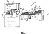
- FIG. 1 schematically illustrates a gas turbine engine 20.
- the gas turbine engine 20 is disclosed herein as a two-spool turbofan that generally incorporates a fan section 22, a compressor section 24, a combustor section 26 and a turbine section 28.
- the fan section 22 drives air along a bypass flow path B in a bypass duct defined within a housing 15 such as a fan case or nacelle, and also drives air along a core flow path C for compression and communication into the combustor section 26 then expansion through the turbine section 28.
- the exemplary engine 20 generally includes a low speed spool 30 and a high speed spool 32 mounted for rotation about an engine central longitudinal axis A relative to an engine static structure 36 via several bearing systems 38. It should be understood that various bearing systems 38 at various locations may alternatively or additionally be provided, and the location of bearing systems 38 may be varied as appropriate to the application.
- the low speed spool 30 generally includes an inner shaft 40 that interconnects, a first (or low) pressure compressor 44 and a first (or low) pressure turbine 46.
- the inner shaft 40 is connected to the fan 42 through a speed change mechanism, which in exemplary gas turbine engine 20 is illustrated as a geared architecture 48 to drive a fan 42 at a lower speed than the low speed spool 30.
- the high speed spool 32 includes an outer shaft 50 that interconnects a second (or high) pressure compressor 52 and a second (or high) pressure turbine 54.
- a combustor 56 is arranged in exemplary gas turbine 20 between the high pressure compressor 52 and the high pressure turbine 54.
- a mid-turbine frame 57 of the engine static structure 36 may be arranged generally between the high pressure turbine 54 and the low pressure turbine 46.
- the mid-turbine frame 57 further supports bearing systems 38 in the turbine section 28.
- the inner shaft 40 and the outer shaft 50 are concentric and rotate via bearing systems 38 about the engine central longitudinal axis A which is colline
- the core airflow is compressed by the low pressure compressor 44 then the high pressure compressor 52, mixed and burned with fuel in the combustor 56, then expanded through the high pressure turbine 54 and low pressure turbine 46.
- the mid-turbine frame 57 includes airfoils 59 which are in the core airflow path C.
- the turbines 46, 54 rotationally drive the respective low speed spool 30 and high speed spool 32 in response to the expansion.
- gear system 48 may be located aft of the low pressure compressor, or aft of the combustor section 26 or even aft of turbine section 28, and fan 42 may be positioned forward or aft of the location of gear system 48.
- the engine 20 in one example is a high-bypass geared aircraft engine.
- the engine 20 bypass ratio is greater than about six (6), with an example embodiment being greater than about ten (10)
- the geared architecture 48 is an epicyclic gear train, such as a planetary gear system or other gear system, with a gear reduction ratio of greater than about 2.3
- the low pressure turbine 46 has a pressure ratio that is greater than about five.
- the engine 20 bypass ratio is greater than about ten (10:1)
- the fan diameter is significantly larger than that of the low pressure compressor 44
- the low pressure turbine 46 has a pressure ratio that is greater than about five 5:1.
- Low pressure turbine 46 pressure ratio is pressure measured prior to inlet of low pressure turbine 46 as related to the pressure at the outlet of the low pressure turbine 46 prior to an exhaust nozzle.
- the geared architecture 48 may be an epicycle gear train, such as a planetary gear system or other gear system, with a gear reduction ratio of greater than about 2.3:1 and less than about 5:1. It should be understood, however, that the above parameters are only exemplary of one embodiment of a geared architecture engine and that the present invention is applicable to other gas turbine engines including direct drive turbofans.
- the fan section 22 of the engine 20 is designed for a particular flight condition -- typically cruise at about 0.8 Mach and about 35,000 feet (10,668 meters).
- the flight condition of 0.8 Mach and 35,000 ft (10,668 meters), with the engine at its best fuel consumption - also known as "bucket cruise Thrust Specific Fuel Consumption ('TSFC')" - is the industry standard parameter of lbm of fuel being burned divided by lbf of thrust the engine produces at that minimum point.
- "Low fan pressure ratio” is the pressure ratio across the fan blade alone, without a Fan Exit Guide Vane (“FEGV”) system.
- the low fan pressure ratio as disclosed herein according to one non-limiting embodiment is less than about 1.45.
- the "Low corrected fan tip speed” as disclosed herein according to one non-limiting embodiment is less than about 1150 ft / second (350.5 meters/second).
- Figure 2 illustrates a line representation of an example of a vane arc segment 60 from the turbine section 28 of the engine 20 (see also Figure 1 ). It is to be understood that although the examples herein are discussed in context of a vane from the turbine section, the examples can be applied to other vanes that have support spars.
- the vane arc segment 60 includes an airfoil 62 that is comprised of an airfoil section 64 and first and second platforms 66/68 between which the airfoil section 64 extends.
- the airfoil section 64 generally extends in a radial direction relative to the central engine axis A.
- the terms such as “inner” and “outer” refer to location with respect to the central engine axis A, i.e., radially inner or radially outer.
- first and “second” used herein is to differentiate that there are two architecturally distinct components or features. It is to be further understood that the terms “first” and “second” are interchangeable in that a first component or feature could alternatively be termed as the second component or feature, and vice versa.
- the airfoil fairing 62 is continuous in that the platforms 66/68 and airfoil section 64 constitute a unitary body.
- the airfoil fairings are formed of a ceramic matrix composite, an organic matrix composite (OMC), or a metal matrix composite (MMC).
- the ceramic matrix composite (CMC) is formed of ceramic fiber tows that are disposed in a ceramic matrix.
- the ceramic matrix composite may be, but is not limited to, a SiC/SiC ceramic matrix composite in which SiC fiber tows are disposed within a SiC matrix.
- Example organic matrix composites include, but are not limited to, glass fiber tows, carbon fiber tows, and/or aramid fiber tows disposed in a polymer matrix, such as epoxy.
- Example metal matrix composites include, but are not limited to, boron carbide fiber tows and/or alumina fiber tows disposed in a metal matrix, such as aluminum.
- a fiber tow is a bundle of filaments. As an example, a single tow may have several thousand filaments.
- the tows may be arranged in a fiber architecture, which refers to an ordered arrangement of the tows relative to one another, such as, but not limited to, a 2D woven ply or a 3D structure.
- the airfoil section 64 circumscribes an interior through-cavity 70.
- the airfoil section 64 may have a single through-cavity 70, or the cavity 70 may be divided into forward and aft sub-cavities by one or more ribs 71.
- the vane arc segment 60 further includes a spar 72 that extends through the through-cavity 70 and mechanically supports the airfoil fairing 62.
- the spar 72 in this example includes a spar platform 72a and a spar leg 72b that extends from the spar platform 72a into the through-cavity 70.
- the spar platform 72a includes attachment features that secure it to a fixed support structure, such as an engine case.
- the spar leg 72b defines an interior through-passage 72c. Cooling air, such as bleed air from the compressor section 24, is conveyed into and through the through-passage 72c of the spar 72. This cooling air is destined for a downstream cooling location, such as a tangential onboard injector (TOBI). Cooling air may also be provided into cavity 70 for cooling of the airfoil section 64.
- TOBI tangential onboard injector
- the spar leg 72b has a distal end portion 74 that has a spar clevis mount 76.
- the end portion 74 of the spar leg 72b extends past the platform 68 of the airfoil fairing 62 so as to protrude from the airfoil fairing 62.
- the support platform 78, the platform 68 of the airfoil fairing 62, or both may have support flanges 79 through which the airfoil fairing 62 may mechanically interface with the spar platform 72a and support platform 78.
- the support platform 78 includes a first through-hole 80a through which the end portion 74 of the spar leg 72b extends such that the spar clevis mount 76 protrudes from the support platform 78.
- a pin 82 extends though the spar clevis mount 76.
- the pin 82 is wider than the through-hole 80a. The ends of the pin 82 thus abut the face of the support platform 78 and thereby prevent the spar leg 72b from being retracted into the through-hole 80a.
- the pin 82 thus locks the support platform 78 to the spar leg 72b such that the airfoil fairing 62 is mechanically trapped between the spar platform 72a and the support platform 78.
- the spar 72 may be formed of a relatively high temperature resistance, high strength material, such as a single crystal metal alloy (e.g., a single crystal nickel- or cobalt-alloy).
- the spar clevis mount 76 includes first and second prongs 76a/76b that have respective pin holes 76c that are coaxially aligned with each other.
- the pin 82 is disposed in the pin holes 76c (after the spar clevis mount 76 is received through the through-hole 80a in the support platform 78).
- the prongs 76a/76b are spaced apart so as to form a forked configuration.
- the through-passage 72c of the spar leg 72b extends between the prongs 76a/76b.
- the spar clevis mount 76 thus also serves as an outlet of the through-passage 72c.
- a "clevis mount” as used herein refers to a fastening system in which there is at least one prong that receives a pin there through in order to fasten the support platform 78 and the spar leg 72b together.
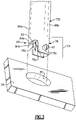
- the support platform 78 ( Figure 2 ) further includes a second through-hole 80b, a forward end 78a, and an aft end 78b.
- the second through-hole 80b is between the first through-hole 80a and the aft end 78b.
- a baffle 84 extends through the cavity 70 (e.g., the aft sub-cavity) of the airfoil fairing 62 and through the second through-hole 80b of the support platform 78.
- the baffle 84 may be formed of, but is not limited to, a nickel-alloy, a cobalt-based superalloy, a titanium alloy, or other alloy if temperature conditions of the particular implementation permit.
- the baffle 84 includes impingement holes, represented at arrows 83, for emitting impingement cooling air onto the wall of the airfoil section 64.
- the baffle 84 includes first and second end portions 84a/84b.
- the first end 84a is secured in a joint, represented at 86, to the support platform 78.
- the joint 86 may be a permanent joint that cannot be unjoined without substantial destruction of one of the components or a non-permanent joint that can readily be joined and unjoined. Whether permanent or non-permanent, the joint 86 serves to secure the baffle 84 and the support platform 78 together.
- the second end portion 84b extends through the spar platform 72a and may be affixed to the outer side of the spar platform 72a (e.g., by welding) or fixed support structure, such as an engine case.
- Figure 4 illustrates a local view of the end portion 74 of the spar leg 72b, the first end 84a of the baffle 84, and the support platform 78.
- the pin 82 abuts the underside of the support platform 78 and thereby radially constrains the support platform 78.
- this radial component of the aerodynamic load AL is located toward the aft end 78a of the support platform 78, the support platform 78 has the tendency to teeter on the pin 82 and thus rotate, as indicated at R1 (clockwise in the illustrated example).
- the forward end 78b of the support platform 78 would tend to rotate radially outwards, as indicated at R2, and exert the load on the forward end of the platform 68 of the airfoil fairing 62.
- Such a load condition is undesired because it increases the stress on the airfoil fairing 62.
- the baffle 84 serves as an anti-rotation feature and limits rotation of the support platform 78 about the pin 82.
- the baffle 84 is secured to the support platform 78 and affixed to the spar platform 72a or fixed support structure.
- the support platform 78 rotates or tends to rotate, it loads the joint 86, thereby placing the baffle 84 in tension.
- the baffle 84 stops the support platform 78 from rotation and thereby prevents the forward end of the support platform 78 from rotating into the forward end of the platform 68.
- the load is thus reacted through the pin 82 to the spar leg 72b instead of to the platform 68 of the airfoil fairing 62.
- the axial distance between the pin 82 and the joint 86 may be maximized in order to increase the mechanical advantage and reduce loads, while relatively shorter distances may impart relatively higher loads on the baffle 84.
- the example configuration may be adapted for other aerodynamic load conditions.
- the baffle 84 may instead be located forward of the spar leg 72b. That is, since the support platform 78 teeters about the pin 82, the baffle 84 is located on the opposite side of the pin 82 from the location at which the load is transmitted into the spar support 78.
- the example configuration could be used in an inverted arrangement, with the spar 72 being inverted such that the spar platform 72a is adjacent the platform 68 and the support platform 78 is adjacent the platform 66.
- the baffle 84 permit the loads to be borne by the spar 72 instead of the platform 68 of the airfoil fairing 62.
- there may also be additional design flexibility in the positioning of the spar leg 72b since the spar leg 72b need not be centrally located in order to balance the loads reacted out at the support platform 78.
- the baffle 84 could be loaded in compression.
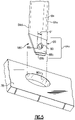
- FIG. 5 illustrates an example joint 186 of the baffle 84 that may be used as described above for joint 86.
- the joint 186 includes a baffle clevis mount 88 on the first end portion 84a of the baffle 84.
- the baffle clevis mount 88 is configured like the spar clevis mount 76 and, like the spar clevis mount 76, will extend past the support platform 78.
- the baffle clevis mount 88 includes first and second prongs 88a/88b that have respective pin holes 88c that are coaxially aligned with each other.
- a pin 90 is disposed in the pin holes 88c (after the baffle clevis mount 88 is received through the through-hole 80b in the support platform 78).
- the prongs 88a/88b are spaced apart so as to form a forked configuration.
- the pin 90 is wider than the through-hole 80b. The ends of the pin 90 thus abut the face of the support platform 78 and thereby prevent the baffle 84 from being retracted into the through-hole 80b. The pin 90 thus locks the support platform 78 to the baffle 84 such that the loads are borne by the baffle 84 in tension as described above.
- both prongs 88a/88b having pin holes 88c
- only one of the prongs 88a/88b has a pin hole 88c, or the prongs 88a/88b may converge into a single prong that has a pin hole 88c.
- the pin 90 is axially offset, as represented at 91, to be nearer an aft side 84c of the baffle 84 than to a forward side 84d of the baffle 84.
- the pin 90 would then be offset to be nearer the forward side 84d of the baffle 84.
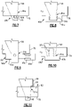
- Figure 6 illustrates another example of a joint 286.
- the joint includes a weldment 92 at which the baffle 84 is welded to the support platform 78.
- the alloy selected for the baffle 84 is compatible with welding, such as a nickel alloy, cobalt alloy, or titanium alloy.
- Figures 7-10 illustrate additional examples.
- the joint 386 includes a notch 93a in the end 84a of the baffle 84 and a lock pin 93b disposed in the notch 93a. Similar to the pin 90 of the prior example, the lock pin 93b prevents retraction of the baffle 84 from the support platform 78.
- the joint 486 includes external threads 94a on the end 84a of the baffle 84 and a nut 94b secured on the threads 94a to prevent retraction of the baffle 84 from the support platform 78.
- the joint 586 includes a clamp 95 that has support 95a and a set screw 95b.
- the joint 686 includes internal threads 97a in the end 84a of the baffle 84 and a bolt 97b secured in the threads 97a to prevent retraction of the baffle 84 from the support platform 78.
- FIG 11 illustrates an example of the baffle 84 for use in compression.
- the baffle 84 has a ledge 98 that catches on the support platform 78.
- the support platform rotates, as indicated at R3
- the support platform 78 bears against the ledge 97, placing the baffle 84 in compression.
Landscapes
- Engineering & Computer Science (AREA)
- Mechanical Engineering (AREA)
- General Engineering & Computer Science (AREA)
- Chemical & Material Sciences (AREA)
- Materials Engineering (AREA)
- Architecture (AREA)
- Composite Materials (AREA)
- Ceramic Engineering (AREA)
- Physics & Mathematics (AREA)
- Fluid Mechanics (AREA)
- Structures Of Non-Positive Displacement Pumps (AREA)
Applications Claiming Priority (1)
| Application Number | Priority Date | Filing Date | Title |
|---|---|---|---|
| US17/213,705 US11371371B1 (en) | 2021-03-26 | 2021-03-26 | Vane with pin mount and anti-rotation baffle |
Publications (2)
| Publication Number | Publication Date |
|---|---|
| EP4086432A1 true EP4086432A1 (de) | 2022-11-09 |
| EP4086432B1 EP4086432B1 (de) | 2024-04-24 |
Family
ID=80978728
Family Applications (1)
| Application Number | Title | Priority Date | Filing Date |
|---|---|---|---|
| EP22164835.5A Active EP4086432B1 (de) | 2021-03-26 | 2022-03-28 | Leitschaufel mit stiftbefestigung und drehsicherem leitblech |
Country Status (2)
| Country | Link |
|---|---|
| US (1) | US11371371B1 (de) |
| EP (1) | EP4086432B1 (de) |
Families Citing this family (1)
| Publication number | Priority date | Publication date | Assignee | Title |
|---|---|---|---|---|
| US11668200B2 (en) * | 2021-01-15 | 2023-06-06 | Raytheon Technologies Corporation | Vane with pin mount and anti-rotation |
Citations (3)
| Publication number | Priority date | Publication date | Assignee | Title |
|---|---|---|---|---|
| EP3034802A1 (de) * | 2014-12-18 | 2016-06-22 | General Electric Company | Verbundwerkstoffdüse mit keramischer matrix befestigt mit einer strebe |
| US20190368360A1 (en) * | 2018-06-01 | 2019-12-05 | Rolls-Royce North American Technologies Inc. | Turbine vane assembly with ceramic matrix composite components |
| FR3098246A1 (fr) * | 2019-07-04 | 2021-01-08 | Safran Aircraft Engines | Turbine de turbomachine à distributeur en CMC avec reprise d’effort |
Family Cites Families (4)
| Publication number | Priority date | Publication date | Assignee | Title |
|---|---|---|---|---|
| US5630700A (en) | 1996-04-26 | 1997-05-20 | General Electric Company | Floating vane turbine nozzle |
| US6164903A (en) * | 1998-12-22 | 2000-12-26 | United Technologies Corporation | Turbine vane mounting arrangement |
| US9970317B2 (en) * | 2014-10-31 | 2018-05-15 | Rolls-Royce North America Technologies Inc. | Vane assembly for a gas turbine engine |
| US10822973B2 (en) | 2017-11-28 | 2020-11-03 | General Electric Company | Shroud for a gas turbine engine |
-
2021
- 2021-03-26 US US17/213,705 patent/US11371371B1/en active Active
-
2022
- 2022-03-28 EP EP22164835.5A patent/EP4086432B1/de active Active
Patent Citations (3)
| Publication number | Priority date | Publication date | Assignee | Title |
|---|---|---|---|---|
| EP3034802A1 (de) * | 2014-12-18 | 2016-06-22 | General Electric Company | Verbundwerkstoffdüse mit keramischer matrix befestigt mit einer strebe |
| US20190368360A1 (en) * | 2018-06-01 | 2019-12-05 | Rolls-Royce North American Technologies Inc. | Turbine vane assembly with ceramic matrix composite components |
| FR3098246A1 (fr) * | 2019-07-04 | 2021-01-08 | Safran Aircraft Engines | Turbine de turbomachine à distributeur en CMC avec reprise d’effort |
Also Published As
| Publication number | Publication date |
|---|---|
| EP4086432B1 (de) | 2024-04-24 |
| US11371371B1 (en) | 2022-06-28 |
Similar Documents
| Publication | Publication Date | Title |
|---|---|---|
| US11346228B1 (en) | Airfoil with flange formed of wishbone-shaped fiber layer structure | |
| US11448075B2 (en) | CMC vane arc segment with cantilevered spar | |
| US12025020B2 (en) | Vane system with continuous support ring | |
| US12006845B2 (en) | Vane arc segment with flange and gusset | |
| EP4030036A1 (de) | Leitschaufelbogensegment-trägerplattform mit gekrümmtem radialem kanal | |
| EP4086432A1 (de) | Leitschaufel mit stiftbefestigung und drehsicherem leitblech | |
| EP4063618B1 (de) | Leitschaufelbogensegment mit federdichtung | |
| EP4053379B1 (de) | Schaufelbogensegment mit holm und stiftverkleidung | |
| US11391163B1 (en) | Vane arc segment with seal | |
| EP4030035B1 (de) | Leitschaufelsegment mit stiftbefestigung und verdrehsicherungs-stabilisierungsstab | |
| US12163446B2 (en) | Vane with pin mount and anti-rotation | |
| US11668199B2 (en) | Vane arc segment with radially projecting flanges | |
| US11708765B1 (en) | Gas turbine engine article with branched flange | |
| US12258881B2 (en) | Turbine section with ceramic support rings and ceramic vane arc segments |
Legal Events
| Date | Code | Title | Description |
|---|---|---|---|
| PUAI | Public reference made under article 153(3) epc to a published international application that has entered the european phase |
Free format text: ORIGINAL CODE: 0009012 |
|
| STAA | Information on the status of an ep patent application or granted ep patent |
Free format text: STATUS: THE APPLICATION HAS BEEN PUBLISHED |
|
| AK | Designated contracting states |
Kind code of ref document: A1 Designated state(s): AL AT BE BG CH CY CZ DE DK EE ES FI FR GB GR HR HU IE IS IT LI LT LU LV MC MK MT NL NO PL PT RO RS SE SI SK SM TR |
|
| STAA | Information on the status of an ep patent application or granted ep patent |
Free format text: STATUS: REQUEST FOR EXAMINATION WAS MADE |
|
| 17P | Request for examination filed |
Effective date: 20230505 |
|
| RBV | Designated contracting states (corrected) |
Designated state(s): AL AT BE BG CH CY CZ DE DK EE ES FI FR GB GR HR HU IE IS IT LI LT LU LV MC MK MT NL NO PL PT RO RS SE SI SK SM TR |
|
| GRAP | Despatch of communication of intention to grant a patent |
Free format text: ORIGINAL CODE: EPIDOSNIGR1 |
|
| STAA | Information on the status of an ep patent application or granted ep patent |
Free format text: STATUS: GRANT OF PATENT IS INTENDED |
|
| RAP3 | Party data changed (applicant data changed or rights of an application transferred) |
Owner name: RTX CORPORATION |
|
| INTG | Intention to grant announced |
Effective date: 20231012 |
|
| GRAS | Grant fee paid |
Free format text: ORIGINAL CODE: EPIDOSNIGR3 |
|
| GRAA | (expected) grant |
Free format text: ORIGINAL CODE: 0009210 |
|
| STAA | Information on the status of an ep patent application or granted ep patent |
Free format text: STATUS: THE PATENT HAS BEEN GRANTED |
|
| AK | Designated contracting states |
Kind code of ref document: B1 Designated state(s): AL AT BE BG CH CY CZ DE DK EE ES FI FR GB GR HR HU IE IS IT LI LT LU LV MC MK MT NL NO PL PT RO RS SE SI SK SM TR |
|
| REG | Reference to a national code |
Ref country code: GB Ref legal event code: FG4D |
|
| REG | Reference to a national code |
Ref country code: CH Ref legal event code: EP |
|
| REG | Reference to a national code |
Ref country code: DE Ref legal event code: R096 Ref document number: 602022002996 Country of ref document: DE |
|
| REG | Reference to a national code |
Ref country code: IE Ref legal event code: FG4D |
|
| REG | Reference to a national code |
Ref country code: LT Ref legal event code: MG9D |
|
| REG | Reference to a national code |
Ref country code: NL Ref legal event code: MP Effective date: 20240424 |
|
| REG | Reference to a national code |
Ref country code: AT Ref legal event code: MK05 Ref document number: 1679782 Country of ref document: AT Kind code of ref document: T Effective date: 20240424 |
|
| PG25 | Lapsed in a contracting state [announced via postgrant information from national office to epo] |
Ref country code: NL Free format text: LAPSE BECAUSE OF FAILURE TO SUBMIT A TRANSLATION OF THE DESCRIPTION OR TO PAY THE FEE WITHIN THE PRESCRIBED TIME-LIMIT Effective date: 20240424 |
|
| PG25 | Lapsed in a contracting state [announced via postgrant information from national office to epo] |
Ref country code: NL Free format text: LAPSE BECAUSE OF FAILURE TO SUBMIT A TRANSLATION OF THE DESCRIPTION OR TO PAY THE FEE WITHIN THE PRESCRIBED TIME-LIMIT Effective date: 20240424 |
|
| PG25 | Lapsed in a contracting state [announced via postgrant information from national office to epo] |
Ref country code: IS Free format text: LAPSE BECAUSE OF FAILURE TO SUBMIT A TRANSLATION OF THE DESCRIPTION OR TO PAY THE FEE WITHIN THE PRESCRIBED TIME-LIMIT Effective date: 20240824 |
|
| PG25 | Lapsed in a contracting state [announced via postgrant information from national office to epo] |
Ref country code: BG Free format text: LAPSE BECAUSE OF FAILURE TO SUBMIT A TRANSLATION OF THE DESCRIPTION OR TO PAY THE FEE WITHIN THE PRESCRIBED TIME-LIMIT Effective date: 20240424 |
|
| PG25 | Lapsed in a contracting state [announced via postgrant information from national office to epo] |
Ref country code: HR Free format text: LAPSE BECAUSE OF FAILURE TO SUBMIT A TRANSLATION OF THE DESCRIPTION OR TO PAY THE FEE WITHIN THE PRESCRIBED TIME-LIMIT Effective date: 20240424 Ref country code: FI Free format text: LAPSE BECAUSE OF FAILURE TO SUBMIT A TRANSLATION OF THE DESCRIPTION OR TO PAY THE FEE WITHIN THE PRESCRIBED TIME-LIMIT Effective date: 20240424 |
|
| PG25 | Lapsed in a contracting state [announced via postgrant information from national office to epo] |
Ref country code: GR Free format text: LAPSE BECAUSE OF FAILURE TO SUBMIT A TRANSLATION OF THE DESCRIPTION OR TO PAY THE FEE WITHIN THE PRESCRIBED TIME-LIMIT Effective date: 20240725 |
|
| PG25 | Lapsed in a contracting state [announced via postgrant information from national office to epo] |
Ref country code: PT Free format text: LAPSE BECAUSE OF FAILURE TO SUBMIT A TRANSLATION OF THE DESCRIPTION OR TO PAY THE FEE WITHIN THE PRESCRIBED TIME-LIMIT Effective date: 20240826 |
|
| PG25 | Lapsed in a contracting state [announced via postgrant information from national office to epo] |
Ref country code: ES Free format text: LAPSE BECAUSE OF FAILURE TO SUBMIT A TRANSLATION OF THE DESCRIPTION OR TO PAY THE FEE WITHIN THE PRESCRIBED TIME-LIMIT Effective date: 20240424 |
|
| PG25 | Lapsed in a contracting state [announced via postgrant information from national office to epo] |
Ref country code: AT Free format text: LAPSE BECAUSE OF FAILURE TO SUBMIT A TRANSLATION OF THE DESCRIPTION OR TO PAY THE FEE WITHIN THE PRESCRIBED TIME-LIMIT Effective date: 20240424 |
|
| PG25 | Lapsed in a contracting state [announced via postgrant information from national office to epo] |
Ref country code: PL Free format text: LAPSE BECAUSE OF FAILURE TO SUBMIT A TRANSLATION OF THE DESCRIPTION OR TO PAY THE FEE WITHIN THE PRESCRIBED TIME-LIMIT Effective date: 20240424 |
|
| PG25 | Lapsed in a contracting state [announced via postgrant information from national office to epo] |
Ref country code: LV Free format text: LAPSE BECAUSE OF FAILURE TO SUBMIT A TRANSLATION OF THE DESCRIPTION OR TO PAY THE FEE WITHIN THE PRESCRIBED TIME-LIMIT Effective date: 20240424 |
|
| PG25 | Lapsed in a contracting state [announced via postgrant information from national office to epo] |
Ref country code: PT Free format text: LAPSE BECAUSE OF FAILURE TO SUBMIT A TRANSLATION OF THE DESCRIPTION OR TO PAY THE FEE WITHIN THE PRESCRIBED TIME-LIMIT Effective date: 20240826 Ref country code: PL Free format text: LAPSE BECAUSE OF FAILURE TO SUBMIT A TRANSLATION OF THE DESCRIPTION OR TO PAY THE FEE WITHIN THE PRESCRIBED TIME-LIMIT Effective date: 20240424 Ref country code: NO Free format text: LAPSE BECAUSE OF FAILURE TO SUBMIT A TRANSLATION OF THE DESCRIPTION OR TO PAY THE FEE WITHIN THE PRESCRIBED TIME-LIMIT Effective date: 20240724 Ref country code: LV Free format text: LAPSE BECAUSE OF FAILURE TO SUBMIT A TRANSLATION OF THE DESCRIPTION OR TO PAY THE FEE WITHIN THE PRESCRIBED TIME-LIMIT Effective date: 20240424 Ref country code: IS Free format text: LAPSE BECAUSE OF FAILURE TO SUBMIT A TRANSLATION OF THE DESCRIPTION OR TO PAY THE FEE WITHIN THE PRESCRIBED TIME-LIMIT Effective date: 20240824 Ref country code: HR Free format text: LAPSE BECAUSE OF FAILURE TO SUBMIT A TRANSLATION OF THE DESCRIPTION OR TO PAY THE FEE WITHIN THE PRESCRIBED TIME-LIMIT Effective date: 20240424 Ref country code: GR Free format text: LAPSE BECAUSE OF FAILURE TO SUBMIT A TRANSLATION OF THE DESCRIPTION OR TO PAY THE FEE WITHIN THE PRESCRIBED TIME-LIMIT Effective date: 20240725 Ref country code: FI Free format text: LAPSE BECAUSE OF FAILURE TO SUBMIT A TRANSLATION OF THE DESCRIPTION OR TO PAY THE FEE WITHIN THE PRESCRIBED TIME-LIMIT Effective date: 20240424 Ref country code: ES Free format text: LAPSE BECAUSE OF FAILURE TO SUBMIT A TRANSLATION OF THE DESCRIPTION OR TO PAY THE FEE WITHIN THE PRESCRIBED TIME-LIMIT Effective date: 20240424 Ref country code: BG Free format text: LAPSE BECAUSE OF FAILURE TO SUBMIT A TRANSLATION OF THE DESCRIPTION OR TO PAY THE FEE WITHIN THE PRESCRIBED TIME-LIMIT Effective date: 20240424 Ref country code: AT Free format text: LAPSE BECAUSE OF FAILURE TO SUBMIT A TRANSLATION OF THE DESCRIPTION OR TO PAY THE FEE WITHIN THE PRESCRIBED TIME-LIMIT Effective date: 20240424 Ref country code: RS Free format text: LAPSE BECAUSE OF FAILURE TO SUBMIT A TRANSLATION OF THE DESCRIPTION OR TO PAY THE FEE WITHIN THE PRESCRIBED TIME-LIMIT Effective date: 20240724 |
|
| PG25 | Lapsed in a contracting state [announced via postgrant information from national office to epo] |
Ref country code: DK Free format text: LAPSE BECAUSE OF FAILURE TO SUBMIT A TRANSLATION OF THE DESCRIPTION OR TO PAY THE FEE WITHIN THE PRESCRIBED TIME-LIMIT Effective date: 20240424 |
|
| PG25 | Lapsed in a contracting state [announced via postgrant information from national office to epo] |
Ref country code: EE Free format text: LAPSE BECAUSE OF FAILURE TO SUBMIT A TRANSLATION OF THE DESCRIPTION OR TO PAY THE FEE WITHIN THE PRESCRIBED TIME-LIMIT Effective date: 20240424 |
|
| PG25 | Lapsed in a contracting state [announced via postgrant information from national office to epo] |
Ref country code: CZ Free format text: LAPSE BECAUSE OF FAILURE TO SUBMIT A TRANSLATION OF THE DESCRIPTION OR TO PAY THE FEE WITHIN THE PRESCRIBED TIME-LIMIT Effective date: 20240424 |
|
| PG25 | Lapsed in a contracting state [announced via postgrant information from national office to epo] |
Ref country code: SK Free format text: LAPSE BECAUSE OF FAILURE TO SUBMIT A TRANSLATION OF THE DESCRIPTION OR TO PAY THE FEE WITHIN THE PRESCRIBED TIME-LIMIT Effective date: 20240424 Ref country code: RO Free format text: LAPSE BECAUSE OF FAILURE TO SUBMIT A TRANSLATION OF THE DESCRIPTION OR TO PAY THE FEE WITHIN THE PRESCRIBED TIME-LIMIT Effective date: 20240424 |
|
| REG | Reference to a national code |
Ref country code: DE Ref legal event code: R097 Ref document number: 602022002996 Country of ref document: DE |
|
| PG25 | Lapsed in a contracting state [announced via postgrant information from national office to epo] |
Ref country code: SM Free format text: LAPSE BECAUSE OF FAILURE TO SUBMIT A TRANSLATION OF THE DESCRIPTION OR TO PAY THE FEE WITHIN THE PRESCRIBED TIME-LIMIT Effective date: 20240424 |
|
| PG25 | Lapsed in a contracting state [announced via postgrant information from national office to epo] |
Ref country code: SM Free format text: LAPSE BECAUSE OF FAILURE TO SUBMIT A TRANSLATION OF THE DESCRIPTION OR TO PAY THE FEE WITHIN THE PRESCRIBED TIME-LIMIT Effective date: 20240424 Ref country code: SK Free format text: LAPSE BECAUSE OF FAILURE TO SUBMIT A TRANSLATION OF THE DESCRIPTION OR TO PAY THE FEE WITHIN THE PRESCRIBED TIME-LIMIT Effective date: 20240424 Ref country code: RO Free format text: LAPSE BECAUSE OF FAILURE TO SUBMIT A TRANSLATION OF THE DESCRIPTION OR TO PAY THE FEE WITHIN THE PRESCRIBED TIME-LIMIT Effective date: 20240424 Ref country code: EE Free format text: LAPSE BECAUSE OF FAILURE TO SUBMIT A TRANSLATION OF THE DESCRIPTION OR TO PAY THE FEE WITHIN THE PRESCRIBED TIME-LIMIT Effective date: 20240424 Ref country code: DK Free format text: LAPSE BECAUSE OF FAILURE TO SUBMIT A TRANSLATION OF THE DESCRIPTION OR TO PAY THE FEE WITHIN THE PRESCRIBED TIME-LIMIT Effective date: 20240424 Ref country code: CZ Free format text: LAPSE BECAUSE OF FAILURE TO SUBMIT A TRANSLATION OF THE DESCRIPTION OR TO PAY THE FEE WITHIN THE PRESCRIBED TIME-LIMIT Effective date: 20240424 |
|
| PLBE | No opposition filed within time limit |
Free format text: ORIGINAL CODE: 0009261 |
|
| STAA | Information on the status of an ep patent application or granted ep patent |
Free format text: STATUS: NO OPPOSITION FILED WITHIN TIME LIMIT |
|
| 26N | No opposition filed |
Effective date: 20250127 |
|
| PG25 | Lapsed in a contracting state [announced via postgrant information from national office to epo] |
Ref country code: SI Free format text: LAPSE BECAUSE OF FAILURE TO SUBMIT A TRANSLATION OF THE DESCRIPTION OR TO PAY THE FEE WITHIN THE PRESCRIBED TIME-LIMIT Effective date: 20240424 |
|
| PG25 | Lapsed in a contracting state [announced via postgrant information from national office to epo] |
Ref country code: SE Free format text: LAPSE BECAUSE OF FAILURE TO SUBMIT A TRANSLATION OF THE DESCRIPTION OR TO PAY THE FEE WITHIN THE PRESCRIBED TIME-LIMIT Effective date: 20240424 |
|
| PG25 | Lapsed in a contracting state [announced via postgrant information from national office to epo] |
Ref country code: MC Free format text: LAPSE BECAUSE OF FAILURE TO SUBMIT A TRANSLATION OF THE DESCRIPTION OR TO PAY THE FEE WITHIN THE PRESCRIBED TIME-LIMIT Effective date: 20240424 |
|
| REG | Reference to a national code |
Ref country code: CH Ref legal event code: H13 Free format text: ST27 STATUS EVENT CODE: U-0-0-H10-H13 (AS PROVIDED BY THE NATIONAL OFFICE) Effective date: 20251023 |
|
| PG25 | Lapsed in a contracting state [announced via postgrant information from national office to epo] |
Ref country code: LU Free format text: LAPSE BECAUSE OF NON-PAYMENT OF DUE FEES Effective date: 20250328 |
|
| REG | Reference to a national code |
Ref country code: BE Ref legal event code: MM Effective date: 20250331 |
|
| PG25 | Lapsed in a contracting state [announced via postgrant information from national office to epo] |
Ref country code: BE Free format text: LAPSE BECAUSE OF NON-PAYMENT OF DUE FEES Effective date: 20250331 |
|
| PG25 | Lapsed in a contracting state [announced via postgrant information from national office to epo] |
Ref country code: CH Free format text: LAPSE BECAUSE OF NON-PAYMENT OF DUE FEES Effective date: 20250331 |
|
| PG25 | Lapsed in a contracting state [announced via postgrant information from national office to epo] |
Ref country code: IE Free format text: LAPSE BECAUSE OF NON-PAYMENT OF DUE FEES Effective date: 20250328 |
|
| PG25 | Lapsed in a contracting state [announced via postgrant information from national office to epo] |
Ref country code: IT Free format text: LAPSE BECAUSE OF FAILURE TO SUBMIT A TRANSLATION OF THE DESCRIPTION OR TO PAY THE FEE WITHIN THE PRESCRIBED TIME-LIMIT Effective date: 20240424 |
|
| PGFP | Annual fee paid to national office [announced via postgrant information from national office to epo] |
Ref country code: GB Payment date: 20260220 Year of fee payment: 5 |
|
| PGFP | Annual fee paid to national office [announced via postgrant information from national office to epo] |
Ref country code: DE Payment date: 20260219 Year of fee payment: 5 |
|
| PGFP | Annual fee paid to national office [announced via postgrant information from national office to epo] |
Ref country code: FR Payment date: 20260219 Year of fee payment: 5 |