EP4086491A1 - Agencement de soupape - Google Patents
Agencement de soupape Download PDFInfo
- Publication number
- EP4086491A1 EP4086491A1 EP22171236.7A EP22171236A EP4086491A1 EP 4086491 A1 EP4086491 A1 EP 4086491A1 EP 22171236 A EP22171236 A EP 22171236A EP 4086491 A1 EP4086491 A1 EP 4086491A1
- Authority
- EP
- European Patent Office
- Prior art keywords
- valve
- valve arrangement
- pressure
- spring
- outlet
- Prior art date
- Legal status (The legal status is an assumption and is not a legal conclusion. Google has not performed a legal analysis and makes no representation as to the accuracy of the status listed.)
- Granted
Links
Images






Classifications
-
- B—PERFORMING OPERATIONS; TRANSPORTING
- B05—SPRAYING OR ATOMISING IN GENERAL; APPLYING FLUENT MATERIALS TO SURFACES, IN GENERAL
- B05B—SPRAYING APPARATUS; ATOMISING APPARATUS; NOZZLES
- B05B1/00—Nozzles, spray heads or other outlets, with or without auxiliary devices such as valves, heating means
- B05B1/30—Nozzles, spray heads or other outlets, with or without auxiliary devices such as valves, heating means designed to control volume of flow, e.g. with adjustable passages
- B05B1/3093—Recirculation valves, i.e. the valve element opens a passage to the nozzle and simultaneously closes at least partially a return passage the feeding means
-
- B—PERFORMING OPERATIONS; TRANSPORTING
- B05—SPRAYING OR ATOMISING IN GENERAL; APPLYING FLUENT MATERIALS TO SURFACES, IN GENERAL
- B05B—SPRAYING APPARATUS; ATOMISING APPARATUS; NOZZLES
- B05B1/00—Nozzles, spray heads or other outlets, with or without auxiliary devices such as valves, heating means
- B05B1/30—Nozzles, spray heads or other outlets, with or without auxiliary devices such as valves, heating means designed to control volume of flow, e.g. with adjustable passages
- B05B1/3006—Nozzles, spray heads or other outlets, with or without auxiliary devices such as valves, heating means designed to control volume of flow, e.g. with adjustable passages the controlling element being actuated by the pressure of the fluid to be sprayed
-
- B—PERFORMING OPERATIONS; TRANSPORTING
- B05—SPRAYING OR ATOMISING IN GENERAL; APPLYING FLUENT MATERIALS TO SURFACES, IN GENERAL
- B05B—SPRAYING APPARATUS; ATOMISING APPARATUS; NOZZLES
- B05B12/00—Arrangements for controlling delivery; Arrangements for controlling the spray area
- B05B12/08—Arrangements for controlling delivery; Arrangements for controlling the spray area responsive to condition of liquid or other fluent material to be discharged, of ambient medium or of target ; responsive to condition of spray devices or of supply means, e.g. pipes, pumps or their drive means
- B05B12/085—Arrangements for controlling delivery; Arrangements for controlling the spray area responsive to condition of liquid or other fluent material to be discharged, of ambient medium or of target ; responsive to condition of spray devices or of supply means, e.g. pipes, pumps or their drive means responsive to flow or pressure of liquid or other fluent material to be discharged
- B05B12/087—Flow or presssure regulators, i.e. non-electric unitary devices comprising a sensing element, e.g. a piston or a membrane, and a controlling element, e.g. a valve
-
- F—MECHANICAL ENGINEERING; LIGHTING; HEATING; WEAPONS; BLASTING
- F16—ENGINEERING ELEMENTS AND UNITS; GENERAL MEASURES FOR PRODUCING AND MAINTAINING EFFECTIVE FUNCTIONING OF MACHINES OR INSTALLATIONS; THERMAL INSULATION IN GENERAL
- F16K—VALVES; TAPS; COCKS; ACTUATING-FLOATS; DEVICES FOR VENTING OR AERATING
- F16K17/00—Safety valves; Equalising valves, e.g. pressure relief valves
- F16K17/02—Safety valves; Equalising valves, e.g. pressure relief valves opening on surplus pressure on one side; closing on insufficient pressure on one side
- F16K17/04—Safety valves; Equalising valves, e.g. pressure relief valves opening on surplus pressure on one side; closing on insufficient pressure on one side spring-loaded
- F16K17/0406—Safety valves; Equalising valves, e.g. pressure relief valves opening on surplus pressure on one side; closing on insufficient pressure on one side spring-loaded in the form of balls
-
- F—MECHANICAL ENGINEERING; LIGHTING; HEATING; WEAPONS; BLASTING
- F16—ENGINEERING ELEMENTS AND UNITS; GENERAL MEASURES FOR PRODUCING AND MAINTAINING EFFECTIVE FUNCTIONING OF MACHINES OR INSTALLATIONS; THERMAL INSULATION IN GENERAL
- F16K—VALVES; TAPS; COCKS; ACTUATING-FLOATS; DEVICES FOR VENTING OR AERATING
- F16K17/00—Safety valves; Equalising valves, e.g. pressure relief valves
- F16K17/02—Safety valves; Equalising valves, e.g. pressure relief valves opening on surplus pressure on one side; closing on insufficient pressure on one side
- F16K17/04—Safety valves; Equalising valves, e.g. pressure relief valves opening on surplus pressure on one side; closing on insufficient pressure on one side spring-loaded
- F16K17/0446—Safety valves; Equalising valves, e.g. pressure relief valves opening on surplus pressure on one side; closing on insufficient pressure on one side spring-loaded with an obturating member having at least a component of their opening and closing motion not perpendicular to the closing faces
- F16K17/046—Safety valves; Equalising valves, e.g. pressure relief valves opening on surplus pressure on one side; closing on insufficient pressure on one side spring-loaded with an obturating member having at least a component of their opening and closing motion not perpendicular to the closing faces the valve being of the gate valve type or the sliding valve type
-
- F—MECHANICAL ENGINEERING; LIGHTING; HEATING; WEAPONS; BLASTING
- F16—ENGINEERING ELEMENTS AND UNITS; GENERAL MEASURES FOR PRODUCING AND MAINTAINING EFFECTIVE FUNCTIONING OF MACHINES OR INSTALLATIONS; THERMAL INSULATION IN GENERAL
- F16K—VALVES; TAPS; COCKS; ACTUATING-FLOATS; DEVICES FOR VENTING OR AERATING
- F16K17/00—Safety valves; Equalising valves, e.g. pressure relief valves
- F16K17/02—Safety valves; Equalising valves, e.g. pressure relief valves opening on surplus pressure on one side; closing on insufficient pressure on one side
- F16K17/04—Safety valves; Equalising valves, e.g. pressure relief valves opening on surplus pressure on one side; closing on insufficient pressure on one side spring-loaded
- F16K17/06—Safety valves; Equalising valves, e.g. pressure relief valves opening on surplus pressure on one side; closing on insufficient pressure on one side spring-loaded with special arrangements for adjusting the opening pressure
Definitions
- the present invention relates to a valve arrangement according to the preamble of claim 1 and a high-pressure cleaning device.
- the present invention relates to safety valve assemblies and circulation valve assemblies.
- the valve arrangement according to the invention can also be used for other applications and can be advantageous.
- Safety valves are used to protect a hydraulic system against unwanted overpressure. They are therefore also referred to as pressure relief valves or pressure relief valves. These terms are therefore preferably to be understood as synonymous below.
- Safety valve arrangements are used in particular in piston pumps, such as a high-pressure cleaning device or water jet cleaning device.
- the opening and closing of a safety valve arrangement is preferably controlled or regulated by the prevailing liquid or water pressure.
- the safety valve arrangement In normal operation, ie in particular at normal operating pressure, the safety valve arrangement is preferably closed. As soon as a certain, so-called response pressure is reached or exceeded, the safety valve arrangement opens. The opening therefore preferably takes place when a critical pressure above the operating pressure is reached or exceeded, in particular in the event of an undesired or impermissible increase in pressure. Fluid can then be drained or diverted from the system via the opened safety valve arrangement, ie in particular the pressure can be lowered again.
- the valve arrangement preferably closes (again) as soon as the pressure has fallen below a certain value, the so-called closing pressure.
- the closing pressure corresponds to the response pressure or is below the response pressure.
- Customary safety valve arrangements known from the prior art comprise a spiral spring which presses directly on a piston and presses or tensions it against a valve seat.
- the safety valve assembly opens when the fluid pressure on the piston exceeds or overcomes the pressure exerted by the spring.
- the spring is encased in a sleeve, which can be turned to adjust the preload force of the spring and thus the response pressure.
- an adjusting screw is installed. The sleeve is then tight and the spring is tensioned via the adjusting screw.
- the present invention also relates to so-called circulation valves, which are also referred to as bypass valves or unloader valves. These terms are therefore preferably to be understood as synonymous below.
- a circulating valve arrangement also blocks and opens as a function of the prevailing liquid or water pressure, so it preferably has at least a similar function to a safety valve arrangement and, as a result, preferably also has a similar structure.
- a circulating valve arrangement preferably serves as a pressure reducer and/or to switch a pump to an idle state.
- a circulating valve arrangement preferably serves to regulate down a pressure and/or to divert or divert a fluid flow, in particular when it is not required. Operation in which such a diversion takes place is also referred to as bypass operation or idle operation.
- a spool valve assembly preferably has at least two functions, namely to idle a pump and to turn down or reduce the pressure.
- a liquid in particular water
- a pump for example, a liquid, in particular water
- a pump for example, a liquid, in particular water
- a pump for example, a liquid, in particular water
- a circulating valve arrangement is preferably used, which diverts the flow of liquid, in particular back to the pump, particularly preferably so that the liquid can be conveyed in a circuit.
- a known from the prior art circulation valve assembly is for example in EP 1 854 558 A2 described.
- the arrangement has an inlet, an outlet and a bypass line.
- a non-return valve is arranged between the inlet and outlet, which is open during normal operation so that liquid can flow from the inlet, in particular a pump connected to the inlet, to the outlet, in particular a valve gun connected to the outlet.
- the bypass line is closed during normal operation.
- a spiral spring is provided, similar to a safety valve arrangement, which preloads a piston rod against a valve seat, here in particular pulling it against the valve seat.
- the non-return valve closes.
- a pressure pulse is created downstream of the check valve, which acts on the piston rod so that it is lifted off the valve seat and the bypass line opens.
- the check valve remains closed and the bypass valve remains open and the liquid is pumped by the pump in the circuit through the bypass line, unless the pump is switched off. If the valve pistol is opened again, the pressure conditions at the circulating valve arrangement change accordingly, so that the bypass valve closes again and the check valve opens.
- the spring is typically encased in a sleeve, with the sleeve being rotatable to adjust the biasing force of the spring. In particular, this adjusts the response pressure, ie the pressure at which the bypass valve opens, in such a way that the bypass line is closed in normal operation and open in idle operation.
- an adjusting screw is installed. The sleeve is then tight and the spring is tensioned via the adjusting screw.
- valve arrangements known from the prior art in particular safety valve arrangements and circulating valve arrangements, there is the problem that the spiral springs used, because of their properties, press obliquely on the valve piston sealing the valve seat. This leads in particular to one-sided wear of the valve piston and a reduced sealing effect.
- a possible solution known from the prior art is to use pressure plates mounted on balls in order to direct the spring force in the effective direction of the valve piston, so that it does not tilt in the housing.
- the problem is that when the spring preload is adjusted, i.e. when the adjusting sleeve is turned, the valve piston can turn with the spring. This leads to increased wear of the valve seat surfaces and reduced valve assembly life.
- Safety valve and/or circulating valve arrangements in particular should open reliably and in a defined manner at the set response pressure. In the event of wear, this can no longer be guaranteed.
- valve piston lifts only slightly from the valve seat. This is due, for example, to the fact that a full stroke cannot be achieved due to excessive friction between the piston rod and a guide for the piston rod.
- the small stroke means that the opening cross-section at the valve seat, and the valve piston diameter accordingly, must be increased in order to achieve a sufficient flow rate. This results in a larger design and a lower sealing effect, since the spring force has to act on a larger sealing surface.
- a proposed valve arrangement which can be a safety valve arrangement or a circulation valve arrangement, for example, has an inlet, an outlet and a valve seat arranged between the inlet and outlet.
- the proposed valve arrangement has a valve element and a spring.
- the valve element in particular at operating pressure, in a Closing position prestressed or prestressable against the valve seat with a prestressing force.
- a fluid connection between the inlet and outlet is then preferably blocked or interrupted.
- the valve element can preferably be lifted off the valve seat into an open position, so that the inlet and outlet are fluidically connected to one another, in particular when a fluid pressure or liquid pressure at the valve arrangement exceeds a response pressure.
- the valve arrangement preferably has an actuation space in which the liquid pressure is present.
- the valve arrangement preferably has an adjustment device, also known as an adjustment device, by means of which the prestressing force exerted by the spring can be adjusted or adjusted, in particular by means of which the spring can be compressed or stretched, preferably by rotating the adjustment device or adjustment device, particularly preferably in the opposite direction an axis of symmetry of the spring. Adjusting or adjusting the prestressing force of the spring preferably causes an adjustment or change in the response pressure.
- the spring is designed as a plunger spring.
- a plunger spring is to be understood here as meaning, in particular, a cylindrical helical spring or compression spring, the wire cross section of which is oval or rectangular, but not circular.
- Other common terms for this type of spring are tool springs and system springs.
- the spring thus differs from the usual spiral springs in the known valve arrangements of the prior art by its non-round or non-circular wire cross-section.
- This has the advantage that the cross-sectional area of the spring is larger than that of conventional round wire, which means that more force can be generated. This is conducive to a more compact design.
- a stamp spring settles less than a spiral spring with a circular wire cross-section.
- “Setting” is to be understood in particular as an irreversible deformation of the spring and/or a reduction in the unstressed length of the spring, which occurs as the spring ages, in particular when it is subjected to higher loads. This reduces the preload force of the spring over time.
- the valve arrangement according to the invention with a plunger spring can thus provide a more precise or constant response pressure, even over a longer period of time be achieved and / or deviations in response pressure over the life of the valve assembly are reduced. This is conducive to less wear or a longer service life of the valve arrangement and/or reliable and defined opening at the set response pressure.
- the valve arrangement is particularly preferably designed without a housing for the spring or without a spring housing or spring sleeve/adjusting sleeve and/or the spring is (at least essentially) free of a housing, a spring housing or a spring sleeve/adjusting sleeve.
- the spring is preferably (at least partially) free or open, in particular to its surroundings or to the atmosphere, or is freely accessible (from the outside). This has the advantage that any moisture that occurs can dry off the spring, so that rusting or corroding of the spring is avoided or at least reduced. In addition, fewer components are required, which is conducive to a simpler and more compact design.
- the valve arrangement has an intermediate element which is arranged between the spring and the valve element or via which the prestressing force of the spring can be transmitted to the valve element.
- the intermediate element is prevented from rotating about a symmetrical or longitudinal axis of the spring, a symmetrical or longitudinal axis of the valve element and/or an axis running in the opening direction of the valve element, and/or against rotating when adjusting the spring or actuating the Adjustment device or adjustment device, secured or stored according to non-rotatable.
- the intermediate element prevents the valve element from rotating.
- the intermediate element advantageously prevents a rotational movement from being transmitted to the valve element when the setting device or adjustment device is actuated or when the prestressing force or the response pressure is set. This reduces wear on the surfaces on the valve seat.
- the prestressing force of the spring is preferably deflected or centered by the intermediate element onto the valve element.
- the prestressing force acts on the valve element only in the axial direction or in the closing direction. Undesirable transverse forces on the valve element can thus be avoided in an advantageous manner, which on the one hand reduce the closing force and on the other hand lead to wear on one side.
- a (drain) line between the valve seat and the drain in particular downstream directly behind the valve seat, has a cross-sectional constriction or nozzle.
- an additional or greater pressure preferably acts on the valve element, in particular on the front side, than would be the case with a valve arrangement without a corresponding cross-sectional constriction.
- a dynamic pressure is preferably generated at the valve seat by the narrowing of the cross section, as a result of which a (complete) lifting of the valve element from the valve seat or a (complete) opening of the valve arrangement is supported.
- Due to the narrowing of the cross section a force or pressure acts on the end face of the valve element in the opening direction or counter to the prestressing force of the spring, particularly preferably at least essentially over the entire surface.
- a force or pressure acts on the annular region of the end face which is in contact with the valve seat in the closed position.
- valve element can be lifted off in various ways.
- the liquid pressure can be present directly at the valve element.
- the valve arrangement or the valve element is then preferably actuated by the liquid pressure acting directly on the valve element.
- valve arrangement can comprise a piston or other actuating element which, when the response pressure is reached or exceeded, presses the valve element off the valve seat against the prestressing force of the spring.
- valve arrangement can also have an outlet, in particular when it is a circulation valve arrangement.
- the inlet and outlet are preferably fluidly connected to one another, and in idling operation, the inlet and outlet are preferably connected to one another, in particular as initially described.
- a non-return valve is particularly preferably arranged between the inlet and outlet in order to separate the fluid connection between the inlet and outlet during idling operation.
- the proposed valve arrangement is preferably designed for high-pressure devices, in particular devices in which the usual operating pressure is at least 50 bar or 100 bar.
- the (minimum) response pressure that can be set on the valve arrangement is particularly preferably more than 50 bar.
- response pressures of more than 100 bar, 200 bar, 500 bar and/or 700 bar can preferably be set.
- the proposed valve arrangement preferably has a mass or weight of less than 1.5 kg, in particular less than 1 kg, and/or more than 0.3 kg or 0.4 kg, particularly preferably about 0.6 kg.
- the proposed valve arrangement can be manufactured or designed with fewer components or use of material and/or lighter than the usual valve arrangements known from the prior art.
- a further aspect of the present invention relates to a high-pressure cleaning device with a proposed valve arrangement. Corresponding advantages can be achieved in this way.
- a high-pressure cleaning device is preferably a device in which a liquid, in particular water, is delivered under high pressure, in particular for cleaning purposes.
- the liquid pressure here is preferably at least 50 bar, preferably 100 bar to 500 bar or more.
- a proposed high-pressure cleaning device particularly preferably has at least two proposed valve arrangements, one of the valve arrangements being a circulation valve arrangement and the other of the valve arrangements being a safety valve arrangement.
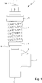
- Figures 1 to 4 show a proposed valve assembly 1 according to a first embodiment.
- the valve arrangement 1 is shown in a schematic side view and in 2 in a view rotated by 90°.
- 3 shows a schematic section of the valve assembly 1.
- the valve assembly 1 is shown in the closed position. 4 shows a cut corresponding to 3 with the valve assembly 1 in the open position.
- the valve arrangement 1 preferably has an inlet 2 and an outlet 3 .
- the inlet 2 and/or the outlet 3 are designed in particular as connections to the hoses or lines are connectable.
- the inlet 2 and/or outlet 3 preferably have appropriate connection devices, such as threads, quick-release couplings or the like.
- the valve arrangement 1 according to the first embodiment particularly preferably has exactly two connections, formed by the inlet 2 and the outlet 3 .
- the inlet 2 and the outlet 3 are preferably arranged or formed on a (common) main body or housing 4 of the valve arrangement 1 .
- the inlet 2 and the outlet 3 are preferably fluidly connected or can be connected, in particular via an inlet line 2A and/or an outlet line 3A.
- the inlet line 2A is preferably arranged or formed behind or downstream of the inlet 2 and/or in front of or upstream of the outlet 3 or the outlet line 3A.
- the outlet line 3A is preferably arranged or formed before or upstream of the outlet 3 and/or behind or downstream of the inlet 2 or the inlet line 2A.
- downstream and upstream refer here and in the following to the usual direction of flow of liquid, in particular water, during operation of the valve arrangement 1 (when it is open), in which the liquid flows through the valve arrangement 1 from the inlet 2 to the outlet 3 flows through.
- the inlet duct 2A and/or the outlet duct 3A are formed in the main body 4, respectively.
- the inlet 2 and the outlet 3 or their opening directions or the inlet line 2A and the outlet line 3A are preferably arranged transversely, in particular perpendicularly, to one another.
- other solutions are also possible here.
- a valve seat 5 is preferably arranged or formed between the inlet 2 and the outlet 3, in particular the inlet line 2A and the outlet line 3A.
- the valve seat 5 can be formed directly in or by the main body or the housing 4 and/or the inlet line 2A or the outlet line 3A, or, as in FIG 3 and 4 represented by an insert 5A.
- the insert 5A is preferably arranged or fixed in the inlet line 2A and/or outlet line 3A in a sealing or form-fitting manner.
- the insert 5A is fixed by means of a counterpart, in particular the counterpart being screwed into a screw channel of the drain line 3A.
- other solutions are also possible here.
- the valve arrangement 1 preferably has a valve element 6 which, in the closed position, such as in particular in 3 shown, sealingly against the valve seat 5 rests.
- the contact surface is preferably ring-shaped.
- the "closed position" of the valve arrangement 1 is preferably to be understood as meaning the position in which the valve element 6 rests against the valve seat 5 in a sealing manner.
- the fluid connection between inlet 2 and outlet 3, in particular inlet line 2A and outlet line 3A, is interrupted or closed or blocked, in particular by the sealing contact of valve element 6 on valve seat 5.
- the valve element 6 is preferably movably mounted or can be lifted off the valve seat 5, so that a fluid connection between the inlet 2 and the outlet 3, in particular the inlet line 2A and the outlet line 3A, is opened, released or established.
- the position in which the valve element 6 is (completely) lifted or moved away from the valve seat 5 is referred to below as the “open position” of the valve arrangement 1 . This is in 4 shown, which will be discussed in more detail later.
- valve element 6 is elongate or cylindrical or designed as a piston.
- other solutions are also possible here.
- the valve element 6 is preferably guided in the main body or housing 4 in a sealing manner.
- the valve arrangement 1 preferably has a clamping element or a spring 7 .
- the valve arrangement 1 or the valve element 6 is (pre)tensioned, preferably in the closed position or against the valve seat 5.
- the spring 7 is preferably a coil spring or a spring in which a spring wire 7A is wound in a helical form and/or helically.
- the spring 7 is a (helical) compression spring or coiled torsion spring. Under the action of an external load, in particular in the direction of the (screw) axis A of the spring 7 or compression of the spring 7, the spring wire 7A is preferably subject to torsion and an opposing force acts.
- the winding pitch of the spring 7 is preferably constant.
- the number of turns of the spring 7 is preferably greater than 4 or 5, and/or less than 16, in particular less than 12 or 10.
- the length of the spring 7 is preferably more than 4 cm, in particular more than 6 cm, and/or less than 10 cm, in particular less than 8 cm.
- the spring 7 is preferably spiral-shaped and/or has a preferably at least essentially cylindrical outer shape. However, slightly conical springs or the like are also conceivable.
- the spring 7 is preferably wound from a wire, in particular the spring wire 7A, which has an oval or rectangular cross-section or whose cross-section is non-circular, as in particular in the section according to FIG 3 and 4 shown.
- the cross section here means in particular the section perpendicular to the (longitudinal) axis of the wire, in particular the spring wire 7A, or a section along the (longitudinal) axis A or axis of symmetry or cylinder axis of the spring 7.
- the wire, in particular the spring wire 7A is preferably a square wire or profile wire, but not a round wire.
- the spring 7 particularly preferably has a rectangular wire cross section or the wire, in particular the spring wire 7A, is rectangular.
- a (helical or compression) spring with an oval or rectangular wire cross-section, i.e. with a non-circular or round wire cross-section, is also referred to as a stamp spring, tool spring or system spring.
- the spring 7 is preferably a stamp spring, tool spring or system spring.
- the spring 7 is preferably arranged on the valve arrangement 1 in such a way that its (longitudinal or spring) axis A corresponds to the opening or closing direction of the valve arrangement 1 or the valve element 6, and/or that a prestressing force of the spring 7 in Closing direction or on the valve element 6 acts.
- axial and radial preferably refer to the axis A or the axis A defined by the opening and closing direction of the valve arrangement 1.
- the axis A of the spring 7 or the closing direction of the valve element 6 corresponds to the direction of flow in the discharge line 3A (when the valve arrangement 1 is open).
- other solutions are also possible here.
- the spring 7 is preferably prestressed or mounted with a prestress.
- the valve arrangement 1 preferably has a first bearing element 8 on the side of the spring 7 facing away from the housing 4 or valve element 6 and/or a second bearing element 9 on the side of the spring 7 facing the housing 4 or valve element 6 .
- the spring 7 is preferably mounted or pretensioned between the bearing elements 8, 9, in particular compressed.
- the bearing elements 8, 9 are preferably plate-shaped or disk-shaped, in particular annular disk-shaped. In particular, the bearing elements 8, 9 form pressure plates or pressure washers.
- the prestressing or prestressing force of the spring 7 or the compression of the spring 7 and/or the distance between the bearing elements 8, 9 can preferably be set or adjusted, in particular by means of an adjustment device 10 of the valve arrangement 1.
- the adjustment device 10 preferably has a tensioning element 10A or is formed by such.
- the spring 7 and/or the bearing element 8 are/is tensioned against the tensioning element 10A.
- the setting device 10 is particularly preferably actuated by rotating the setting device 10, in particular the tensioning element 10A, in particular about an axis of symmetry of the setting device 10 or the tensioning element 10A and/or about the axis A of the spring 7.
- the adjustment device 10 is formed by a nut as a tensioning element 10A and a corresponding threaded rod 10B or has this.
- the threaded rod 10B preferably runs along the (spring) axis A or extends into the spring 7.
- the bearing element 8 is preferably moved towards or away from the bearing element 9 - depending on the direction of rotation - and/or the distance between the bearing elements 8, 9 and/or the compression or preload of the spring 7 is reduced or increased. elevated.
- an (internal) thread could also be formed directly on the bearing element 8, so that the bearing element 8 forms the tensioning element 10A. It is also possible that a screw is used as the clamping element 10A. The spring 7 and/or the bearing element 8 are/is then preferably tensioned against the screw head. Such a solution is exemplary for the second embodiment in Figures 5 to 7 shown.
- the valve arrangement 1 can optionally have a cover 11 in order to cover (partially or completely) the adjustment device 10, the tensioning element 10A and/or the bearing element 8 .
- the cover 11 preferably does not extend over the entire length of the spring 7 or preferably does not cover the spring 7 or only partially, in particular only one or two turns.
- the cover 11 can also be omitted entirely, as exemplified for the second embodiment in FIG Figures 5 to 7 shown.
- the spring 7 is particularly preferably arranged outside of the housing 4 and/or arranged at least substantially free of a housing and/or exposed or open to the environment or freely accessible from the outside.
- the valve arrangement 1 preferably has an intermediate element 12 .
- the intermediate element 12 is preferably arranged or mounted between the spring 7 or the bearing element 9 and the valve element 6 .
- the intermediate element 12 preferably extends radially or transversely, in particular perpendicularly, to the axis A.
- the intermediate element 12 is preferably mounted or arranged in a recess 4A or a gap, in particular of the main body or housing 4 .
- the recess 4A is in particular in 2 shown.
- the section of the recess 4A covered by the bearing element 9 is in 2 shown dashed.
- the intermediate element 12 is preferably secured or blocked against a rotary movement about the axis A, in particular in the recess 4A and/or in a form-fitting manner, and/or is mounted non-rotatably with respect to a rotation about the axis A.
- the intermediate element 12 is preferably mounted so that it can move axially.
- the recess 4A preferably extends in the axial direction, so that the intermediate element 12 can move in the recess 4A when opening or lifting the valve element 6 in the opening direction and when closing or lowering the valve element 6 in the closing direction, as in particular in 2 shown.
- the spring 7 preferably exerts a force, in particular a prestressing force, on the intermediate element 12, in particular via the bearing element 9.
- a force in particular a prestressing force
- the intermediate element 12 is preferably in direct contact with the valve element 6 , in particular axially, and/or is designed to transmit the prestressing force of the spring 7 to the valve element 6 .
- the valve element 6 is particularly preferably in contact with a central region of the intermediate element 6 or the intermediate element 12 is designed to center or deflect the prestressing force of the spring 7 onto the valve element 6 .
- the spring 7 or its prestressing force preferably acts axially on the intermediate element 12 and/or on an outer area or edge area or the outer ends of the intermediate element 12.
- the prestressing force of the spring 7 is preferably deflected via the intermediate element 12 or runs through the intermediate element 12 in the radial direction from the edge area or the outer ends of the intermediate element 12 into a central area or towards the axis A.
- the central area preferably acts in the axial direction on the valve element 6 or directs the force axially onto the valve element 6.
- the intermediate element 12 preferably forms an anti-twist device for the valve element 6.
- the valve arrangement 1 or the intermediate element 12 is preferably designed in such a way that when the spring 7 or its prestressing force is set or adjusted, or when the setting device 10 or the tensioning element 10A is actuated, in particular rotated, only forces in the axial direction or The closing direction can be transferred or can be transferred to the valve element 6 . Preferably, no torsional and/or shearing forces act on the valve element 6.
- the adjustment device 10 when the adjustment device 10 is actuated, torsional forces can occur which cause the first bearing element 8, the spring 7 and/or the second bearing element 9 to rotate about the adjustment axis, ie in particular the axis A.
- the intermediate element 12 is secured or blocked against such a rotary movement, in particular due to the bearing in the recess 4A. Accordingly, the rotational movement or torsional force is not transmitted to the valve element 6 .
- the intermediate element 12 is designed to absorb or dissipate the rotational movement or torsional forces, or to shield the valve element 6 from them.
- the intermediate element 12 is preferably designed as a feather key.
- the intermediate element 12 can also be a cotter pin, pin, bar or the like. It is also not necessary for the intermediate element 12 to be of elongate or pin-like design.
- the intermediate element 12 could also be anti-rotation (positive) be a secured cylinder piece or the like, for example a cylinder piece with at least one radially extending projection which positively engages in a corresponding recess.
- the valve arrangement 1 preferably weighs less than 1.5 kg, in particular less than 1 kg, and/or more than 0.3 kg or 0.4 kg, particularly preferably about 0.6 kg.
- valve arrangement 1 can preferably be connected to a system, plant or device (not shown), in particular with its inlet 2.
- valve 3 shows the valve arrangement 1 in the closed position, in which the valve element 6 is tensioned against the valve seat 5 or rests sealingly, in particular due to the spring 7 or its pretensioning force, which is particularly preferably deflected or centered on the valve element 6 by means of the intermediate element 12.
- a fluid connection between the inlet 2 and the outlet 3 is blocked or interrupted.
- a liquid preferably water, is present at the inlet 2 or in the inlet line 2A at a pressure which preferably corresponds to the pressure prevailing in the system or plant or device to which the Valve assembly 1 is connected by means of the inlet 2.
- the valve arrangement 1 preferably has an actuating means 13 in order to actuate or open the valve arrangement 1, in particular as a function of the fluid pressure, or to establish a fluid connection between the inlet 2 and the outlet 3.
- valve arrangement 1 or the actuating means 13 has an actuating space 14 which is preferably arranged or formed in the main body or housing 4 and/or downstream of the inlet 2 and/or upstream of the valve seat 5 .
- the valve assembly 1 is preferably for this purpose designed so that in the connected state a liquid with its liquid pressure is present or can be present on the actuating means 13 or in the actuating space 14 .
- the liquid pressure preferably acts with a force on the valve element 6 in the axial direction or in the opening direction or opposite to the prestressing force or closing direction, or the valve arrangement 1 is designed for this purpose.
- the actuating means 13 or the valve element 6 has an actuating section 15 for this purpose, in particular a step or an (annular) surface extending in the radial direction.
- other solutions are also possible here, in particular as will be explained later for the other embodiments.
- the valve arrangement 1 is preferably set or adjusted, in particular by means of the setting device 10, so that it remains in the closed position at (normal) operating pressure.
- the prestressing force of the spring 7, which acts on the valve element 6 in the closing direction is greater than the compressive force of the liquid, which acts on the valve element 6 or its actuating section 15 in the opening direction. The resulting force therefore acts in the closing direction.
- Operating pressure is preferably to be understood as meaning the (liquid) pressure at which the system or plant or device to which the valve arrangement 1 or its inlet 2 is connected is or can be operated, and /or the (liquid) pressure for which the system, plant or device is designed.
- the operating pressure is therefore preferably the normally prevailing pressure of the system or the plant or device (in operation).
- “operating pressure” is preferably not to be understood as meaning a specific pressure, but rather a pressure range, for example 50 to 200 bar or 50 to 500 bar.
- the direction of the resulting force preferably changes and then acts in the opening direction.
- the pressure required for this is also referred to as the response pressure.
- the response pressure is preferably above the operating pressure (range) or the maximum pressure for which the system or the plant or device to the / the the valve arrangement 1 or whose inlet 2 is connected is designed. However, the response pressure is preferably below a maximum permissible excess pressure of the system or the plant or device.
- the response pressure is preferably at most 5%, 10% or 15% above the maximum permissible operating pressure.
- valve element 6 When the response pressure is reached or exceeded, the valve element 6 is preferably lifted off the valve seat 5 or moved in the opening direction, in particular against the biasing force of the spring 7 . This preferably leads to an axial movement of the intermediate element 12 and/or bearing element 9 in the opening direction or to a (further) compression of the spring 7.
- the stroke of the valve element 6 or how far the valve element 6 is lifted from the valve seat 5 preferably depends on the liquid pressure.
- the stroke increases (continuously) with increasing pressure until a maximum stroke is reached.
- the pressure required for the maximum stroke is also referred to as the opening pressure.
- the valve arrangement 1 is preferably fully open. This is an example in 4 shown.
- the relationship between pressure and stroke is preferably at least essentially linear.
- the opening pressure is preferably below the maximum permissible excess pressure of the system or the plant or device.
- the opening pressure is preferably at most 5%, 10% or 15% above the response pressure. It is also possible for the valve element 6 to open directly with full lift when the response pressure is reached, ie the opening pressure corresponds at least essentially to the response pressure.
- liquid can flow from the inlet 2 to the outlet 3.
- the volume flow or the flow rate or flow rate from the inlet 2 to the outlet 3 preferably depends on the stroke of the valve element 6, the volume flow being greater the more the valve element 6 is lifted.
- the valve arrangement 1 or the discharge line 3A preferably has a nozzle or cross-sectional constriction 16 behind or downstream of the valve seat 5 .
- the cross-sectional constriction 16 can be formed directly in the main body or housing 4 or the discharge line 3A, or by an insert in the discharge line 3A, preferably by the same insert 5A that also forms the valve seat 5.
- a cross-sectional constriction 16 is preferably to be understood here as meaning that the effective or hydraulic cross-section through which liquid can flow is smaller in the region of the cross-sectional constriction 16 than at the valve seat 5.
- the valve seat 5 preferably delimits an opening through which the liquid can flow when the valve element is lifted 6 can flow to the outlet 3, the opening cross section preferably being larger than the cross section of the cross-sectional constriction 16 arranged downstream.
- the hydraulic diameter of the valve seat opening is preferably greater than the hydraulic diameter of the cross-sectional constriction 16.
- the opening cross-section of the opening delimited by the valve seat 5 and the cross-section of the cross-sectional constriction 16 are preferably circular, the diameter of the cross-sectional constriction 16 being smaller.
- other solutions are also possible here, as will be explained later with reference to the further embodiments.
- a pressure increase or an additional pressure or a back pressure is preferably generated by the cross-sectional constriction 16 upstream of the cross-sectional constriction, in particular in comparison to a valve arrangement without a cross-sectional constriction 16.
- the stroke of the valve element 6 is preferably supported or facilitated by the narrowing of the cross section 16 or the associated dynamic pressure.
- an (additional) compressive force preferably acts on the valve element 6 in the opening direction and/or on the (axial) end face 6A of the valve element 6, in particular at least essentially over the entire surface.
- the cross-sectional constriction 16 preferably achieves a greater stroke of the valve element 6 or faster or wider opening of the valve arrangement 1, in particular in comparison to a valve arrangement without a cross-sectional constriction 16.
- the cross-sectional constriction 16 preferably forms a dynamic opening aid.
- the pressure preferably drops (again).
- the valve assembly 1 preferably closes (again) when the force acting on the valve element 6 corresponds to the biasing force of the spring 7 and/or the liquid pressure in the plant or device or the system or at the inlet 2 of the valve assembly 1 is below a certain pressure , the so-called closing pressure, falls.
- the closing pressure is particularly preferably below the response pressure, in particular by more than 2%, 5%, 10% or 15%.
- the closing pressure can be above or below the maximum permissible operating pressure.
- the closing pressure is preferably above the maximum permissible operating pressure.
- a closing pressure that is lower than the response pressure is preferably achieved by the cross-sectional constriction 16 .
- the cross-sectional constriction 16 causes additional pressure on the valve element 6. If the liquid pressure in the plant or device or the system or at the inlet 2 has (again) reached the response pressure, the valve element 6 preferably does not act only the response pressure force, but also the pressure force caused by the cross-sectional constriction 16 . In particular, the total compressive force is even greater than the prestressing force, so that the valve arrangement 1 remains open. Only when the closing pressure has been reached or fallen below has the compressive force on the valve element 6 preferably decreased to such an extent that the closed position is assumed (again).
- the prestressing force of the spring 7 must preferably be overcome.
- the response pressure can preferably be set or adjusted via the setting device 10 .
- the response pressure is a property of the valve arrangement 1, namely the pressure required for opening.
- the opening pressure and/or closing pressure are preferably dependent on the response pressure and are determined in particular by the design or geometry of the valve arrangement 1, for example the diameter of the cross-sectional constriction 16.
- the valve arrangement 1 is preferably designed for a liquid pressure or operating pressure of at least 50 bar, in particular 100 bar or 200 bar and/or at most 300 bar, 500 bar or 700 bar.
- the adjustable response pressure is preferably at least 10, 20 or 50 bar, in particular 100 bar or 200 bar and/or at most 300 bar, 500 bar or 700 bar.
- the valve arrangement 1 according to the first embodiment is preferably a safety valve arrangement.
- a fluid connection is to be blocked or released under pressure control.
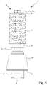
- FIG. 5 to 7 a second embodiment of the proposed valve assembly 1 is shown, which can be used in particular as a safety valve assembly.
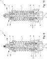
- FIG. 5 shows figure 5 the valve assembly 1 according to the second embodiment in a schematic side view and Figures 6 and 7 each in a schematic section in the closed position or open position.
- the second embodiment differs from the first embodiment in particular in the design or arrangement of the inlet 2, outlet 3, main body or housing 4, valve seat 5 and/or valve element 6.
- the same explanations and explanations regarding the spring 7 preferably apply.
- the clamping element 10A of the adjustment device 10 is preferably designed as a screw.
- other solutions are also possible here, in particular as described for the first embodiment.
- valve element 6 is preferably designed as a valve ball.
- the valve arrangement 1 preferably has a piston rod 17 between the intermediate element 12 and the valve element 6, which is in particular designed as a valve ball.
- the prestressing force exerted by the spring 7 can be transmitted from the intermediate element 12 via the piston rod 17 to the valve element 6, which is designed in particular as a valve ball.
- the valve element 6 embodied in particular as a valve ball can be tensioned or tensioned by the piston rod 17 against the valve seat 5 .
- valve element 6 could itself be piston-shaped and/or abut directly against the intermediate element 12, as in the first embodiment, and/or the piston rod 17 could be formed integrally with the valve element 6, e.g. B. have a hemispherical, axial end.
- the main body or the housing 4 is preferably at least essentially cylindrical.
- the opening direction of the inlet 2 or the inlet line 2A preferably runs in the axial direction.
- the actuating means 13 is preferably formed by the surface of the valve element 6 facing the inlet 2 and/or the actuating space 14 directly in front of the valve element 6 .
- the valve arrangement 1 preferably opens or the valve element 6 is lifted, in particular together with the piston rod 17, when the compressive force on the actuating means 13 or on the surface of the valve element 6 facing the inlet 2 reaches or exceeds the prestressing force exerted on the valve element 6 by the spring 7 . This takes place in particular at the (set) response pressure, as described for the first embodiment.
- the valve arrangement 1 in particular the main body or the housing 4 , preferably has one or more transverse channels 18 downstream of the valve seat 5 .
- the transverse channels 18 preferably run radially or transversely, in particular orthogonally, to the axis A or the inlet line 2A or the opening/closing direction of the valve element 6.
- transverse channels 18 distributed over the circumference of the valve arrangement 1 or the main body or housing 4 are provided, for example 2, 4, 6 or 8 transverse channels 18.
- the transverse channels 18 preferably open out on the outside of the main body or housing 4 or into the environment.
- the transverse channels 18 can (together) form the outlet 3 .
- the valve arrangement 1 preferably has a deflection part 19 .
- the deflection part 19 is conical or truncated or has the shape of the lateral surface of a truncated cone.
- the deflection part 19 preferably surrounds or encloses the main body or the housing 4 (radially), at least partially, in particular in the region of the transverse channels 18.
- the axis of symmetry of the deflection part 19 preferably corresponds to the axis A.
- the opening diameter of the deflection part 19 increases in the direction of the Inlet 2 or in the closing direction of the valve element 6 to.
- the deflection part 19 is preferably fastened to the housing 4 .
- Liquid escaping from the transverse channels 18 can be deflected or deflected via the deflection part 19 .
- (Radially) escaping liquid can preferably be deflected in another direction, in particular in the axial direction, in particular by the conical shape, preferably by the liquid bouncing off the deflection part 19 or its inner wall.
- the deflection part 19 is preferably open at its axial, widened end, so that the liquid can escape there into the environment.
- the outlet 3 is formed in this way.
- the drain 3 preferably has an annular opening and/or surrounds the main body or housing 4 and/or is bounded (radially) by the main body or housing 4 and the deflector part 19 .
- the direction of flow of liquid exiting the outlet 3 is preferably opposite to the direction of flow of liquid entering through the inlet 2 .
- liquid is preferably not drained off via a line or hose, or the outlet 3 has no connection for a line or hose.
- the liquid is preferably discharged or drained directly into the environment, in particular via the transverse channels 18 and/or the deflection part 19. This can preferably ensure that if the valve arrangement 1 is opened, liquid is drained and the liquid pressure is reduced accordingly, in particular since no hose or the like can be used for draining, which in turn could be blocked.
- the cross-sectional constriction 16 is preferably formed by the transverse channels 18 . In this way, corresponding effects and advantages as described for the first embodiment can be achieved.
- the cross-sectional constriction 16 is preferably to be understood as the sum of the cross-sections of the individual transverse channels 18 , in particular the hydraulic cross-section of the transverse channels 18 or the (total) flow cross-section of a liquid flowing through the transverse channels 18 .
- the (hydraulic) cross section of the opening of the valve seat 5 is larger than the (hydraulic) cross section of the transverse channels 18 or the sum of all individual cross sections of the transverse channels 18.
- the hydraulic diameter of the valve seat opening is larger than the hydraulic diameter of the through the Cross channels 18 is formed.
- the liquid when it flows through the opened valve seat 5 and then through the transverse channels 18, in particular to a dynamic pressure upstream of the transverse channels 18, preferably due to the (hydraulic) narrowing of the cross section 16 formed by the transverse channels 18.
- This preferably leads to the same or corresponding effects and advantages as described for the first embodiment, in particular faster opening and/or larger stroke and/or closing pressure lying below the response pressure.
- a third embodiment of the proposed valve arrangement 1 is shown, which can be used in particular as a safety valve arrangement.
- the valve assembly 1 according to the third embodiment in a schematic side view and Figures 9 and 10 each in a schematic section in the closed position or open position.
- the valve arrangement 1 according to the third embodiment is preferably designed similarly to the valve arrangement 1 according to the second embodiment, in particular with transverse channels 18 and an optional deflection part 19.
- the valve arrangement 1 according to the third embodiment differs from the valve arrangement 1 according to the second embodiment essentially by the formation of the valve element 6.
- valve element 6 is sleeve-shaped or at least essentially hollow-cylindrical and/or surrounds or encloses the in particular at least essentially cylindrical main body or housing 4.
- the axis of symmetry of the valve element 6 preferably corresponds to the axis A and/or the main body or housing 4 and the valve element 6 are preferably arranged concentrically to one another.
- the valve seat 5 is preferably formed at or (immediately) downstream of the openings of the transverse channels 18, which is particularly preferably annular and/or closed in the closed position by the particularly sleeve-shaped valve element 6.
- valve seat 5 is preferably formed by a sealing ring or the like, which (radially) surrounds or encloses the main body or the housing 4 .
- a sealing ring or the like which (radially) surrounds or encloses the main body or the housing 4 .
- valve element 6 When the response pressure is reached or exceeded, the valve element 6 can be moved or lifted off the valve seat 5, preferably against the biasing force of the spring 7.
- the valve element 6 has an (annular) actuating surface for this purpose and/or an (annular) actuating space 14 is formed between the outlet openings of the transverse channels 18 and the valve seat 5 .
- an annular gap is preferably released through which the liquid can be discharged into the environment, in particular via the deflection part 19.
- the annular gap on the valve seat 5 can form the cross-sectional constriction 16 .
- the (hydraulic) cross section or hydraulic diameter of the gap (immediately) downstream of the valve seat 5 is smaller than the (hydraulic) cross section or hydraulic diameter of the (sum of) transverse channels 18 upstream of the valve seat 5.
- the deflection part 19 is preferably arranged or attached to the valve element 6 .
- the deflection part 19 can be moved together with the valve element 6 .
- valve arrangement 1 preferably has no intermediate element 12 .
- valve arrangement 1 preferably also has an anti-rotation device (not shown), which in particular allows an axial movement of the valve element 6 but prevents or blocks a rotary movement about the axis A.
- the valve element 6 can have projections pointing radially inwards, which are guided axially in corresponding grooves of the main body or housing 4, or vice versa.
- an anti-twist device is also conceivable in the other embodiments.
- valve arrangement 1 according to the third embodiment can also have an intermediate element 12 as described and illustrated for the other embodiments.
- a fourth embodiment of the proposed valve arrangement 1 is shown, which can be used in particular as a circulation valve arrangement.
- the valve assembly 1 according to the fourth embodiment in a schematic side view and 12 and 13 each in a schematic section in the closed position or open position.
- biasing force of spring 7 also acts in the fourth embodiment in the same direction as in the previous embodiments, i.e. in particular axially in the direction of intermediate element 12 or valve seat 5 or valve element 6 or main body/housing 4.
- Spring 7 is preferred a compression spring.
- the spring 7 according to the fourth embodiment in particular as in the other embodiments, is provided on its side facing away from the main body/housing 4 or valve seat 5 or valve element 6 or intermediate element 12 or the side on which the adjustment device 10 is provided is mounted immovably during operation or movably only for adjusting the prestressing force of the spring 7 and otherwise fixed axially.
- the side of the spring 7 that faces the main body/housing 4 or valve seat 5 or valve element 6 or intermediate element 12 or the side that faces away from the adjusting device 10 is movably mounted, in particular so that the spring 7 can be released when the Valve element 6 is compressed by the valve seat 5, or in such a way (directly) coupled to the valve element 6 that an axial movement or lifting of the valve element 6 leads to a corresponding axial movement of the end of the spring 7 on this side.
- the spring used in particular also a compression spring, acts in exactly the opposite direction and pulls the valve element against the valve seat.
- the side of the spring facing the main body or housing or valve seat is fixedly mounted. Accordingly, the side facing away, in particular the side with the adjustment device, is also movably mounted during operation, in particular so that lifting the valve element from the valve seat leads to an axial movement of this end, in particular together with the adjustment device, or to a compression of the spring.
- this design means that the valve element or a piston rod formed by it must extend through the entire spring in the prior art so that the spring can exert a corresponding prestressing force on the valve element.
- valve element 6 is preferably designed as a piston or has a piston, in particular as in the first embodiment.
- other solutions are also possible here, for example with a valve ball as in the second embodiment.
- the valve element 6 preferably only extends as far as the intermediate element 12.
- the valve arrangement 1 or the valve element 6 does not have a piston rod which—at least partially—extends through the spring 7, as is customary in the prior art.
- the valve arrangement 1 according to the fourth embodiment preferably has an outlet 20 which is different from the inlet 2 and the outlet 3.
- the inlet 2, the outlet 3 and/or the outlet 20 are preferably designed as connections to which hoses or lines can be connected.
- the inlet 2, outlet 3 and/or outlet 20 preferably have corresponding connection devices, such as threads, quick-release couplings or the like.
- the inlet 2 and outlet 20 or their openings or connections are preferably arranged opposite one another and/or a liquid can flow through the valve arrangement 1 at least essentially in a straight line from the inlet 2 to the outlet 20 .
- the outlet 3 or its opening or connection is preferably arranged transversely, in particular orthogonally, to the inlet 2 and/or outlet 20 .
- the inlet 2, outlet 3 and/or outlet 20 are preferably arranged transversely, in particular orthogonally, to the opening or closing direction of the valve element 6 and/or the axis A.
- the inlet direction or outlet direction, the discharge direction and the opening/closing direction or axis A are each transverse, in particular orthogonal, to one another.
- other arrangements are also possible here, in particular through a corresponding design of the main body or housing 4.
- a check valve 21 is preferably arranged between the inlet 2 and the outlet 20 .
- the valve arrangement 1 is preferably designed in such a way, or the response pressure is set in such a way that the check valve 21 is open during normal operation and the valve formed by the valve seat 5 and the valve element 6 is closed.
- This position is preferably the closed position of the valve arrangement 1.
- the terms "closed position” and “open position” therefore preferably refer to the valve seat 5 or the valve element 6, in particular as in the other embodiments.
- the valve arrangement 1 can be in the closed/open position when the check valve 21 is open/closed.
- Normal operation is preferably to be understood as an operation of the valve arrangement 1 or the plant, the system or the device to which the valve arrangement 1 is connected, during which a liquid is discharged downstream of the outlet 20 . This will be discussed in more detail later with reference to 14 received, which shows an example of the use of the proposed valve assembly 1 in a high-pressure cleaning device. "Normal operation” is also referred to as "conveying operation”.
- the inlet 2 and the outlet 20 are preferably fluidically connected and/or the inlet 2 and the outlet 3 are fluidically separated.
- the outlet 3 and the outlet 20 are preferably not fluidically connectable or are (permanently) sealed from one another, in particular both in the closed position and in the open position of the valve arrangement 1.
- a control channel 22 is preferably provided downstream of the check valve 21 or between the check valve 21 and the outlet 20 , which fluidically connects the outlet 20 to the actuation chamber 14 .
- the actuating space 14 is preferably arranged or formed annularly and/or concentrically to the axis A.
- the valve arrangement 1 preferably has a piston 23 .
- the piston 23 preferably delimits the actuation space 14 axially and/or is arranged symmetrically to the axis A or the opening or closing direction of the valve element 6 .
- the axis of symmetry of the piston 23 corresponds to the axis A.
- the piston 23 is preferably arranged between the actuation chamber 14 and the valve element 6 and/or lies upstream of the valve seat 5 or on the inlet side on the valve element 6 and/or is connected to it.
- the biasing force of the spring 7 acts, in particular via the valve element 6, on the piston 23 or tensions it against the main body or the housing 4, as shown in FIG 12 shown.
- the piston 23 preferably has a step or the like, so that the actuation space 14 is formed between the main body/housing 4 and the step of the piston 23 .
- the piston 23 is preferably arranged transversely, in particular orthogonally, to the inlet direction or inlet line 2A.
- the piston 23 preferably protrudes through the inlet line 2A or liquid can flow around it in the inlet line 2A.
- the piston 23 can have a reduced diameter in the area of the inlet line 2A.
- the actuating means 13 preferably has the actuating space 14 and/or the piston 23 or is formed by them.
- the valve arrangement 1 is preferably designed to separate the fluidic connection between the inlet 2 and the outlet 20 and/or to establish a fluidic connection between the inlet 2 and the outlet 3 when the fluid pressure on the outlet side or at the outlet 20 and/or in the actuation chamber 14 exceeds the response pressure reached or exceeded.
- a pressure increase or pressure peak or a pressure pulse occurs on the outlet side. This preferably causes the check valve 21 to be closed or the fluid connection between the inlet 2 and the outlet 20 to be blocked.
- the piston 23 is preferably designed to lift the valve element 6 off the valve seat 5 when the response pressure is reached or exceeded.
- the increase in pressure or pressure peak or the pressure pulse at outlet 20 preferably causes an increase in pressure in actuation chamber 14 or on piston 23, in particular via control channel 22 is moved or pressed, so that the valve element 6 resting on or attached to the piston 23 is lifted off the valve seat 5 .
- the open position is in 13 shown.
- the check valve 21 is preferably closed and the valve element 6 is lifted off the valve seat 5 so that a fluid connection between the inlet 2 and the outlet 20 is interrupted and a fluid connection between the inlet 2 and the outlet 3 is established.
- valve arrangement 1 in the case of the valve arrangement 1 according to the fourth embodiment, a narrowing of the cross section 16 behind the valve seat 5, as in the other embodiments, can be provided and advantageous.
- the response pressure is preferably set or adjustable in such a way that it lies between the normal operating pressure and the increased pressure when the liquid outlet downstream of the outlet 20 is interrupted.
- the response pressure is preferably between 510 bar and 650 bar.
- the valve assembly 1 is in normal operation or when liquid can escape downstream of the outlet 20 in the closed position - in particular with open check valve 21 - and / or idle operation or when a Escape of liquid downstream of the outlet 20 is blocked in the open position - in particular with the check valve 21 closed.
- a proposed high-pressure cleaning device 100 is shown in a block diagram-like view, which preferably has at least one proposed valve arrangement 1 .
- the high-pressure cleaning device 100 preferably has two proposed valve arrangements 1, namely a first valve arrangement 1, which is designed as a circulation valve arrangement 1A, and a second valve arrangement 1, which is designed as a safety valve arrangement 1B.
- FIG. 14 shows the high-pressure cleaning device 100 in conveying operation, in which a liquid, in particular water, preferably as a jet S, is discharged from the high-pressure cleaning device 100.
- the high-pressure cleaning device 100 preferably has a pump 110, in particular a high-pressure pump.
- the pump 110 is preferably connected to the circulating valve arrangement 1A, in particular its inlet 2, via a supply line 120.
- the high-pressure cleaning device 100 preferably has a valve pistol 130 which is connected in particular via a connecting line 140 to the circulating valve arrangement 1A, in particular to its outlet 20 .
- a return line 150 of the high-pressure cleaning device 100 is preferably connected to the circulation valve arrangement 1A, in particular its outlet 3.
- the high-pressure cleaning device 100 is preferably connected or connectable (not shown) upstream of the pump 110 to a liquid reservoir, a water line, a water distribution system or the like. It is also possible for the high-pressure cleaning device 100 to have a liquid reservoir, a liquid container or the like.
- the pump 110 is switched on and the valve pistol 130 is actuated or opened.
- a liquid in particular water, in particular from a reservoir or the like
- the valve gun preferably through supply line 120, circulation valve arrangement 1A and/or connecting line 140.
- Inlet 2 and outlet 20 of circulation valve arrangement 1A are preferably fluidic with one another connected, in particular the check valve 21 is open.
- the liquid is preferably delivered as a jet S via the valve pistol 130, in particular under high pressure.
- High pressure is preferably understood to mean a pressure of at least 50 bar or 100 bar.
- a jet S can preferably be emitted by means of the high-pressure cleaning device 100 under a pressure of up to 500 bar or 700 bar or more.
- the operating pressure or working pressure of the high-pressure cleaning device 100 is at least 50 bar or 100 bar, in particular at least 300 bar, and/or at most 700 bar, in particular at most 500 bar.
- the volume flow of the liquid through the valve arrangement 1 is preferably more than 10 l/min, in particular more than 25 l/min, and/or less than 100 l/min, in particular less than 75 l/min.
- the safety valve arrangement 1B is preferably connected downstream of the pump 110 or upstream of the circulating valve arrangement 1A or between the pump 110 and the circulating valve arrangement 1A or to the supply line 120, in particular with its inlet 2. During delivery operation, the safety valve arrangement 1B is preferably in the closed position, in the inlet 2 and outlet 3 are fluidically separated.
- the pretensioning forces of the respective springs 7 of the valve assemblies 1 are preferably set in such a way that during delivery operation or in the operating pressure (range) then prevailing, the valve assemblies 1 are in their closed position or the respective valve elements 6 are tensioned against the respective valve seats 5. If the valve gun 130 is closed - while the pump 110 is running - and in particular the jet S is interrupted, this preferably leads to a pressure pulse in the connecting line 140 which exceeds the response pressure of the circulating valve arrangement 1A or corresponds to it, so that the circulating valve arrangement 1A assumes the open position, in which the inlet 2 and outlet 3 are fluidly connected.
- the check valve 21 is preferably closed, in particular by the pressure pulse, or the fluid connection between the inlet 2 and the outlet 20 is interrupted.
- the liquid is preferably directed to the return line 150 via the circulation valve assembly 1A.
- the liquid is preferably discharged via the return line 150 or fed back into the system upstream of the pump 110, for example fed back into the reservoir.
- Operation with the valve gun 130 closed is also referred to as idling operation.
- the liquid is pumped and/or circulated into the return line 150 via the pump 110 and the circulating valve arrangement 1A.
- the safety valve arrangement 1B is preferably in the closed position in (normal) idling operation.
- the response pressure of the safety valve arrangement 1B is set in such a way that it is above the operating pressure (range) in delivery operation and idle operation.
- valve pistol 130 If the valve pistol 130 is opened (again), this preferably leads to a drop in pressure in the connecting line 140 and/or at the outlet 20 or actuation chamber 14 of the circulating valve arrangement 1A.
- the drop in pressure preferably leads to a closing movement of the valve element 6 of the circulation valve arrangement 1A, in particular due to the prestressing force of the spring 7, so that the closed position is assumed (again).
- the closed position preferably leads to an increase in pressure in the supply line 120 or at the inlet 2 or the inlet line 2A of the circulation valve arrangement 1A, in particular due to the conveying of the liquid by means of the pump 110, so that the check valve 21 opens (again) and liquid (again) is conveyed to the outlet 20 so that it can be delivered to the valve gun 130.
- the high-pressure cleaning device 100 is then preferably (again) in delivery mode.
- the response pressure of the safety valve arrangement 1B is preferably set in such a way that the safety valve arrangement 1B remains in the closed position even if the pressure rises briefly, caused by the change between delivery operation and idling operation or vice versa.
- the response pressure is preferably above the pressures occurring during these changes.
- the safety valve arrangement 1B or its response pressure is preferably set in such a way that it only opens when the pressure is higher than the pressures that usually occur, for example 5% or 10% higher.
- liquid is preferably drained off or removed from the system or the high-pressure cleaning device 100 via the safety valve arrangement 1B, as explained above, so that the pressure can drop again or the overpressure can be relieved.
- the safety valve arrangement 1B preferably closes (again) when the closing pressure is reached, which is preferably below the response pressure.
- the safety valve arrangement 1B is preferably connected to the supply line 120 . In this way, it is ensured that the safety valve arrangement 1B can trigger or open both during delivery operation and during idling operation.
Landscapes
- Engineering & Computer Science (AREA)
- General Engineering & Computer Science (AREA)
- Mechanical Engineering (AREA)
- Safety Valves (AREA)
Priority Applications (2)
| Application Number | Priority Date | Filing Date | Title |
|---|---|---|---|
| EP23181931.9A EP4242779A3 (fr) | 2021-05-03 | 2022-05-03 | Agencement de soupape |
| EP24161335.5A EP4357874A3 (fr) | 2021-05-03 | 2022-05-03 | Agencement de soupape |
Applications Claiming Priority (2)
| Application Number | Priority Date | Filing Date | Title |
|---|---|---|---|
| DE102021002304 | 2021-05-03 | ||
| DE102021002454.0A DE102021002454A1 (de) | 2021-05-03 | 2021-05-10 | Ventilanordnung |
Related Child Applications (4)
| Application Number | Title | Priority Date | Filing Date |
|---|---|---|---|
| EP24161335.5A Division EP4357874A3 (fr) | 2021-05-03 | 2022-05-03 | Agencement de soupape |
| EP24161335.5A Division-Into EP4357874A3 (fr) | 2021-05-03 | 2022-05-03 | Agencement de soupape |
| EP23181931.9A Division EP4242779A3 (fr) | 2021-05-03 | 2022-05-03 | Agencement de soupape |
| EP23181931.9A Division-Into EP4242779A3 (fr) | 2021-05-03 | 2022-05-03 | Agencement de soupape |
Publications (3)
| Publication Number | Publication Date |
|---|---|
| EP4086491A1 true EP4086491A1 (fr) | 2022-11-09 |
| EP4086491B1 EP4086491B1 (fr) | 2025-10-22 |
| EP4086491C0 EP4086491C0 (fr) | 2025-10-22 |
Family
ID=81580364
Family Applications (3)
| Application Number | Title | Priority Date | Filing Date |
|---|---|---|---|
| EP24161335.5A Pending EP4357874A3 (fr) | 2021-05-03 | 2022-05-03 | Agencement de soupape |
| EP23181931.9A Pending EP4242779A3 (fr) | 2021-05-03 | 2022-05-03 | Agencement de soupape |
| EP22171236.7A Active EP4086491B1 (fr) | 2021-05-03 | 2022-05-03 | Agencement de soupape |
Family Applications Before (2)
| Application Number | Title | Priority Date | Filing Date |
|---|---|---|---|
| EP24161335.5A Pending EP4357874A3 (fr) | 2021-05-03 | 2022-05-03 | Agencement de soupape |
| EP23181931.9A Pending EP4242779A3 (fr) | 2021-05-03 | 2022-05-03 | Agencement de soupape |
Country Status (1)
| Country | Link |
|---|---|
| EP (3) | EP4357874A3 (fr) |
Cited By (3)
| Publication number | Priority date | Publication date | Assignee | Title |
|---|---|---|---|---|
| EP4596123A1 (fr) | 2024-02-01 | 2025-08-06 | Suttner GmbH | Ensemble soupape et procédé de fabrication d'un ensemble soupape |
| DE102024103655A1 (de) * | 2024-02-01 | 2025-08-07 | Suttner Gmbh | Ventilanordnung und Verfahren zum Herstellen einer Ventilanordnung |
| CN121088859A (zh) * | 2025-11-12 | 2025-12-09 | 星奇(上海)半导体有限公司 | 一种防逆流密封组件及流控部件 |
Citations (11)
| Publication number | Priority date | Publication date | Assignee | Title |
|---|---|---|---|---|
| US2964310A (en) * | 1958-08-26 | 1960-12-13 | Sundstrand Corp | Spring assembly for relief valves |
| FR1334478A (fr) * | 1962-06-28 | 1963-08-09 | P Berthoud Ets | Perfectionnements aux clapets limiteurs de pression, notamment pour pulvérisateurs agricoles et analogues |
| DE2704754A1 (de) * | 1977-02-04 | 1978-08-17 | Speck Kolbenpumpen Fabrik | Ventilanordnung |
| US4474208A (en) * | 1983-04-13 | 1984-10-02 | Baird Manufacturing Company | Safety valve |
| DE19838947C1 (de) * | 1998-08-12 | 1999-11-25 | Frank Arbeiter | Bypassventilanordnung für ein Hochdruckreinigungsgerät sowie Hochdruckreinigungsgerät mit einer solchen Bypassventilanordnung |
| EP1854558A2 (fr) | 2006-05-08 | 2007-11-14 | Suttner GmbH | Ensemble de vanne |
| DE102007021381A1 (de) * | 2006-05-08 | 2007-11-22 | Suttner Gmbh | Ventilanordnung |
| WO2013090036A1 (fr) * | 2011-12-12 | 2013-06-20 | Carrier Corporation | Soupape de sûreté de pression à chapeau de protection |
| ITTO20120916A1 (it) * | 2012-10-17 | 2014-04-18 | Mtm Hydro S R L | Valvola di bypass per un impianto di lavaggio |
| US20150276076A1 (en) * | 2013-05-31 | 2015-10-01 | Marathon Valve LLC | Pressure Relief Valve |
| DE202017003786U1 (de) * | 2017-06-02 | 2018-06-06 | Suttner Gmbh | Ventilanordnung und Ventilbaugruppe |
Family Cites Families (2)
| Publication number | Priority date | Publication date | Assignee | Title |
|---|---|---|---|---|
| DE2208014A1 (de) * | 1972-02-21 | 1972-08-30 | Hehl Karl | Verschlussduese fuer spritzgussverarbeitung von thermoplasten |
| IT201800007616A1 (it) * | 2018-07-30 | 2020-01-30 | Tecomec Srl | Valvola di by-pass e di regolazione di una pressione |
-
2022
- 2022-05-03 EP EP24161335.5A patent/EP4357874A3/fr active Pending
- 2022-05-03 EP EP23181931.9A patent/EP4242779A3/fr active Pending
- 2022-05-03 EP EP22171236.7A patent/EP4086491B1/fr active Active
Patent Citations (11)
| Publication number | Priority date | Publication date | Assignee | Title |
|---|---|---|---|---|
| US2964310A (en) * | 1958-08-26 | 1960-12-13 | Sundstrand Corp | Spring assembly for relief valves |
| FR1334478A (fr) * | 1962-06-28 | 1963-08-09 | P Berthoud Ets | Perfectionnements aux clapets limiteurs de pression, notamment pour pulvérisateurs agricoles et analogues |
| DE2704754A1 (de) * | 1977-02-04 | 1978-08-17 | Speck Kolbenpumpen Fabrik | Ventilanordnung |
| US4474208A (en) * | 1983-04-13 | 1984-10-02 | Baird Manufacturing Company | Safety valve |
| DE19838947C1 (de) * | 1998-08-12 | 1999-11-25 | Frank Arbeiter | Bypassventilanordnung für ein Hochdruckreinigungsgerät sowie Hochdruckreinigungsgerät mit einer solchen Bypassventilanordnung |
| EP1854558A2 (fr) | 2006-05-08 | 2007-11-14 | Suttner GmbH | Ensemble de vanne |
| DE102007021381A1 (de) * | 2006-05-08 | 2007-11-22 | Suttner Gmbh | Ventilanordnung |
| WO2013090036A1 (fr) * | 2011-12-12 | 2013-06-20 | Carrier Corporation | Soupape de sûreté de pression à chapeau de protection |
| ITTO20120916A1 (it) * | 2012-10-17 | 2014-04-18 | Mtm Hydro S R L | Valvola di bypass per un impianto di lavaggio |
| US20150276076A1 (en) * | 2013-05-31 | 2015-10-01 | Marathon Valve LLC | Pressure Relief Valve |
| DE202017003786U1 (de) * | 2017-06-02 | 2018-06-06 | Suttner Gmbh | Ventilanordnung und Ventilbaugruppe |
Cited By (3)
| Publication number | Priority date | Publication date | Assignee | Title |
|---|---|---|---|---|
| EP4596123A1 (fr) | 2024-02-01 | 2025-08-06 | Suttner GmbH | Ensemble soupape et procédé de fabrication d'un ensemble soupape |
| DE102024103655A1 (de) * | 2024-02-01 | 2025-08-07 | Suttner Gmbh | Ventilanordnung und Verfahren zum Herstellen einer Ventilanordnung |
| CN121088859A (zh) * | 2025-11-12 | 2025-12-09 | 星奇(上海)半导体有限公司 | 一种防逆流密封组件及流控部件 |
Also Published As
| Publication number | Publication date |
|---|---|
| EP4242779A2 (fr) | 2023-09-13 |
| EP4357874A2 (fr) | 2024-04-24 |
| EP4086491B1 (fr) | 2025-10-22 |
| EP4086491C0 (fr) | 2025-10-22 |
| EP4242779A3 (fr) | 2023-10-18 |
| EP4357874A3 (fr) | 2024-06-05 |
Similar Documents
| Publication | Publication Date | Title |
|---|---|---|
| EP4086491B1 (fr) | Agencement de soupape | |
| EP0096303B1 (fr) | Limiteur de pression | |
| EP1409873B1 (fr) | Bloc de distribution pour un dispositif de regulation, en particulier une machine hydrostatique | |
| EP3645885B1 (fr) | Appareil de nettoyage à haute pression | |
| EP1373718A1 (fr) | Soupape de limitation de pression pour systemes d'injection de carburant | |
| DE102004014485B3 (de) | Druckbegrenzungsventil in einer Hydraulikmaschine und Hydraulikmaschine mit einem Druckbegrenzungsventil | |
| DE4202853A1 (de) | Druckventil | |
| EP1828651B1 (fr) | Soupape de limitation de pression presentant une surface differentielle reduite | |
| EP4060210B1 (fr) | Clapet anti-retour | |
| DE19614446C1 (de) | Fettpresse | |
| DE102021002454A1 (de) | Ventilanordnung | |
| DE3800377C1 (en) | By-pass valve for a high-pressure cleaning appliance | |
| EP2172680A2 (fr) | Agencement de vanne | |
| DE19710983C2 (de) | Rückschlagventil | |
| DE19536725C2 (de) | Vorgesteuertes Druckabschaltventil | |
| EP1854557A2 (fr) | Ensemble de vanne | |
| WO1990012232A1 (fr) | Soupape pour milieux sous pression | |
| DE3201432A1 (de) | Daempfungseinrichtung fuer steuerkolben | |
| DE102010044824B4 (de) | Ventil | |
| DE8312106U1 (de) | Druckbegrenzungsventil | |
| EP3788284B1 (fr) | Dispositif de réglage de la pression de fluides | |
| DE102019218402B4 (de) | Federdom für ein Hydraulikventil und Hydraulikventil mit einem solchen Federdom | |
| DE29606658U1 (de) | Fettpresse | |
| AT364966B (de) | Einspritzpumpe-duese zur direkten kraftstoffeinspritzung | |
| DE10004975C2 (de) | Mehrstufiges hydraulisches Druckbegrenzungsventil |
Legal Events
| Date | Code | Title | Description |
|---|---|---|---|
| PUAI | Public reference made under article 153(3) epc to a published international application that has entered the european phase |
Free format text: ORIGINAL CODE: 0009012 |
|
| STAA | Information on the status of an ep patent application or granted ep patent |
Free format text: STATUS: THE APPLICATION HAS BEEN PUBLISHED |
|
| AK | Designated contracting states |
Kind code of ref document: A1 Designated state(s): AL AT BE BG CH CY CZ DE DK EE ES FI FR GB GR HR HU IE IS IT LI LT LU LV MC MK MT NL NO PL PT RO RS SE SI SK SM TR |
|
| STAA | Information on the status of an ep patent application or granted ep patent |
Free format text: STATUS: REQUEST FOR EXAMINATION WAS MADE |
|
| 17P | Request for examination filed |
Effective date: 20230330 |
|
| RBV | Designated contracting states (corrected) |
Designated state(s): AL AT BE BG CH CY CZ DE DK EE ES FI FR GB GR HR HU IE IS IT LI LT LU LV MC MK MT NL NO PL PT RO RS SE SI SK SM TR |
|
| STAA | Information on the status of an ep patent application or granted ep patent |
Free format text: STATUS: EXAMINATION IS IN PROGRESS |
|
| 17Q | First examination report despatched |
Effective date: 20240702 |
|
| GRAP | Despatch of communication of intention to grant a patent |
Free format text: ORIGINAL CODE: EPIDOSNIGR1 |
|
| STAA | Information on the status of an ep patent application or granted ep patent |
Free format text: STATUS: GRANT OF PATENT IS INTENDED |
|
| INTG | Intention to grant announced |
Effective date: 20250528 |
|
| RAP3 | Party data changed (applicant data changed or rights of an application transferred) |
Owner name: SUTTNER GMBH |
|
| GRAS | Grant fee paid |
Free format text: ORIGINAL CODE: EPIDOSNIGR3 |
|
| GRAA | (expected) grant |
Free format text: ORIGINAL CODE: 0009210 |
|
| STAA | Information on the status of an ep patent application or granted ep patent |
Free format text: STATUS: THE PATENT HAS BEEN GRANTED |
|
| AK | Designated contracting states |
Kind code of ref document: B1 Designated state(s): AL AT BE BG CH CY CZ DE DK EE ES FI FR GB GR HR HU IE IS IT LI LT LU LV MC MK MT NL NO PL PT RO RS SE SI SK SM TR |
|
| REG | Reference to a national code |
Ref country code: CH Ref legal event code: F10 Free format text: ST27 STATUS EVENT CODE: U-0-0-F10-F00 (AS PROVIDED BY THE NATIONAL OFFICE) Effective date: 20251022 Ref country code: GB Ref legal event code: FG4D Free format text: NOT ENGLISH |
|
| REG | Reference to a national code |
Ref country code: DE Ref legal event code: R096 Ref document number: 502022005824 Country of ref document: DE |
|
| REG | Reference to a national code |
Ref country code: IE Ref legal event code: FG4D Free format text: LANGUAGE OF EP DOCUMENT: GERMAN |
|
| U01 | Request for unitary effect filed |
Effective date: 20251120 |
|
| U07 | Unitary effect registered |
Designated state(s): AT BE BG DE DK EE FI FR IT LT LU LV MT NL PT RO SE SI Effective date: 20251205 |
|
| PG25 | Lapsed in a contracting state [announced via postgrant information from national office to epo] |
Ref country code: ES Free format text: LAPSE BECAUSE OF FAILURE TO SUBMIT A TRANSLATION OF THE DESCRIPTION OR TO PAY THE FEE WITHIN THE PRESCRIBED TIME-LIMIT Effective date: 20251022 |
|
| PG25 | Lapsed in a contracting state [announced via postgrant information from national office to epo] |
Ref country code: NO Free format text: LAPSE BECAUSE OF FAILURE TO SUBMIT A TRANSLATION OF THE DESCRIPTION OR TO PAY THE FEE WITHIN THE PRESCRIBED TIME-LIMIT Effective date: 20260122 |
|
| PG25 | Lapsed in a contracting state [announced via postgrant information from national office to epo] |
Ref country code: HR Free format text: LAPSE BECAUSE OF FAILURE TO SUBMIT A TRANSLATION OF THE DESCRIPTION OR TO PAY THE FEE WITHIN THE PRESCRIBED TIME-LIMIT Effective date: 20251022 |
|
| PG25 | Lapsed in a contracting state [announced via postgrant information from national office to epo] |
Ref country code: RS Free format text: LAPSE BECAUSE OF FAILURE TO SUBMIT A TRANSLATION OF THE DESCRIPTION OR TO PAY THE FEE WITHIN THE PRESCRIBED TIME-LIMIT Effective date: 20260122 |
|
| PG25 | Lapsed in a contracting state [announced via postgrant information from national office to epo] |
Ref country code: IS Free format text: LAPSE BECAUSE OF FAILURE TO SUBMIT A TRANSLATION OF THE DESCRIPTION OR TO PAY THE FEE WITHIN THE PRESCRIBED TIME-LIMIT Effective date: 20260222 |