EP4086494B1 - Dichtringanordnung - Google Patents
Dichtringanordnung Download PDFInfo
- Publication number
- EP4086494B1 EP4086494B1 EP21172128.7A EP21172128A EP4086494B1 EP 4086494 B1 EP4086494 B1 EP 4086494B1 EP 21172128 A EP21172128 A EP 21172128A EP 4086494 B1 EP4086494 B1 EP 4086494B1
- Authority
- EP
- European Patent Office
- Prior art keywords
- sealing ring
- section
- circumferential line
- pipe section
- contact
- Prior art date
- Legal status (The legal status is an assumption and is not a legal conclusion. Google has not performed a legal analysis and makes no representation as to the accuracy of the status listed.)
- Active
Links
Images




Classifications
-
- F—MECHANICAL ENGINEERING; LIGHTING; HEATING; WEAPONS; BLASTING
- F16—ENGINEERING ELEMENTS AND UNITS; GENERAL MEASURES FOR PRODUCING AND MAINTAINING EFFECTIVE FUNCTIONING OF MACHINES OR INSTALLATIONS; THERMAL INSULATION IN GENERAL
- F16L—PIPES; JOINTS OR FITTINGS FOR PIPES; SUPPORTS FOR PIPES, CABLES OR PROTECTIVE TUBING; MEANS FOR THERMAL INSULATION IN GENERAL
- F16L13/00—Non-disconnectable pipe joints, e.g. soldered, adhesive, or caulked joints
- F16L13/14—Non-disconnectable pipe joints, e.g. soldered, adhesive, or caulked joints made by plastically deforming the material of the pipe, e.g. by flanging, rolling
- F16L13/141—Non-disconnectable pipe joints, e.g. soldered, adhesive, or caulked joints made by plastically deforming the material of the pipe, e.g. by flanging, rolling by crimping or rolling from the outside
- F16L13/142—Non-disconnectable pipe joints, e.g. soldered, adhesive, or caulked joints made by plastically deforming the material of the pipe, e.g. by flanging, rolling by crimping or rolling from the outside with a sealing element inserted into the female part before crimping or rolling
-
- F—MECHANICAL ENGINEERING; LIGHTING; HEATING; WEAPONS; BLASTING
- F16—ENGINEERING ELEMENTS AND UNITS; GENERAL MEASURES FOR PRODUCING AND MAINTAINING EFFECTIVE FUNCTIONING OF MACHINES OR INSTALLATIONS; THERMAL INSULATION IN GENERAL
- F16L—PIPES; JOINTS OR FITTINGS FOR PIPES; SUPPORTS FOR PIPES, CABLES OR PROTECTIVE TUBING; MEANS FOR THERMAL INSULATION IN GENERAL
- F16L13/00—Non-disconnectable pipe joints, e.g. soldered, adhesive, or caulked joints
- F16L13/14—Non-disconnectable pipe joints, e.g. soldered, adhesive, or caulked joints made by plastically deforming the material of the pipe, e.g. by flanging, rolling
- F16L13/148—Non-disconnectable pipe joints, e.g. soldered, adhesive, or caulked joints made by plastically deforming the material of the pipe, e.g. by flanging, rolling specially designed to ensure an intended leakage until correct deformation
-
- F—MECHANICAL ENGINEERING; LIGHTING; HEATING; WEAPONS; BLASTING
- F16—ENGINEERING ELEMENTS AND UNITS; GENERAL MEASURES FOR PRODUCING AND MAINTAINING EFFECTIVE FUNCTIONING OF MACHINES OR INSTALLATIONS; THERMAL INSULATION IN GENERAL
- F16L—PIPES; JOINTS OR FITTINGS FOR PIPES; SUPPORTS FOR PIPES, CABLES OR PROTECTIVE TUBING; MEANS FOR THERMAL INSULATION IN GENERAL
- F16L21/00—Joints with sleeve or socket
- F16L21/02—Joints with sleeve or socket with elastic sealing rings between pipe and sleeve or between pipe and socket, e.g. with rolling or other prefabricated profiled rings
- F16L21/03—Joints with sleeve or socket with elastic sealing rings between pipe and sleeve or between pipe and socket, e.g. with rolling or other prefabricated profiled rings placed in the socket before connection
Definitions
- the present invention relates to an arrangement comprising a fitting, a sealing ring and a pipe section according to claim 1.
- the invention is based on the object of providing an assembly comprising a fitting, a sealing ring, and a pipe section, which allows for an improved assembly process.
- the invention is based on the object of providing an assembly comprising a fitting, a sealing ring, and a pipe section which allows an improved assembly process under the condition of a good sealing effect.
- an arrangement comprises a sealing ring which extends around a central axis, a fitting with a sealing ring receptacle into which the sealing ring is inserted, a receptacle space and a pressing zone which can be mechanically pressed, and a pipe which can be pushed into the receptacle of the fitting along an insertion direction.
- the sealing ring receptacle has a free space behind the sealing ring as seen in the insertion direction.
- the sealing ring projects with a contact section radially out of the sealing ring receptacle into the receptacle space in such a way that the end face of the pipe section can be brought into contact with the contact section of the sealing ring when the pipe section is pushed in.
- the sealing ring is tilted from an initial position into a tilted position in such a way that the contact section can be moved in the direction of the free space and comes to rest in the free space.
- Tilting the sealing ring has the advantage that when the pipe section is pushed in, the sealing ring is pushed away, i.e. tilted, from the pipe section. This prevents any sharp edges on the pipe section from damaging the sealing ring. Due to the tilting process, the sealing ring does not offer any significant resistance to the pipe section, which prevents the sharp edges from cutting into the pipe. This is different with fully clamped seals.
- the problem is that sharp edges can damage a sealing ring because the sealing ring can only be displaced from the pipe section with regard to its compression properties.
- the arrangement of the free space eliminates this clamping and the sealing ring can be partially moved into the free space.
- tilting the sealing ring has the advantage of reducing the frictional forces between the pipe section and the sealing ring. Tilting the sealing ring changes its shape relative to the pipe section, a process of insertion, whereby the resistance force opposite to the insertion process becomes smaller.
- the sealing ring performs a tilting movement in the sealing ring receptacle. This means that the sealing ring is tilted around a tilting line that extends around the central axis. The tilting line lies inside the sealing ring. The sealing ring is tilted in the insertion direction.
- the tilting function ensures small insertion forces and large holding forces.
- the pipe section can be an end portion of a pipe.
- the pipe section can also be part of another fitting or a spigot end of a fitting that is to be connected to the fitting equipped with the seal.
- the pressing zone is the zone that is compressed by a pressing tool.
- the pressing zone extends in the direction of the central axis at least over the axial extent of the sealing ring or the axial extent of the sealing ring receptacle.
- the pressing zone also extends into areas adjacent to the sealing ring.
- the sealing ring receptacle is adjoined by a cylindrical area, which is also part of the pressing zone.
- the sealing ring touches the inside of the sealing ring holder both in the initial position and in the tilted position.
- the shape of the sealing ring holder ensures that the sealing ring is radially centered to the central axis. This also ensures that the sealing ring is not levered out of the sealing ring holder when inserted at an angle to the central axis.
- the sealing ring holder extends radially outwards from the holder chamber.
- a “free space” is understood to be a space that is not filled by the seal when the seal is in its initial position.
- the contact section of the sealing ring is preferably the section of the sealing ring which protrudes from the sealing ring receptacle into the receptacle space and can be contacted there by the pipe section to be inserted.
- the sealing ring is positioned in the tilted position in such a way that when a tensile force is applied to the pipe section in the opposite direction to the insertion direction, the sealing ring is pressed against the outside of the pipe section, making it difficult to pull out the pipe section in the opposite direction to the insertion direction.
- the sealing ring is in the tilted position. If there is a separation movement between the pipe section and the fitting, the sealing ring would have to be moved from the tilted position to its original position.
- the sealing ring is in contact with the outside of the pipe section and therefore also acts as a retaining element. However, if a sufficient force is applied, separation between the pipe section and the fitting is still possible, in which case the sealing ring must be compressed accordingly. In other words, when a pull-out force is applied to the pipe section, the sealing ring is moved back towards its original position, which increases the pressure of the sealing ring against the pipe section. A type of self-reinforcing effect occurs, whereby the holding force also increases as the pull-out force increases. This makes assembly easier.
- the inner diameter of the sealing ring is smaller than the outer diameter of the pipe section.
- the sealing ring has a surface area which, in the initial position, lies inside the receiving space in such a way that the end face of the pipe section does not come into contact with the surface area when inserted, and which, when moving from the initial position to the tilting position, is pivoted from the inside of the receiving space to the outside of the pipe section.
- This design has the advantage that the surface area creates a section that does not come into contact with potentially sharp-edged sections of the pipe section and, after tilting, can then be brought into contact with the outside of the pipe section for sealing. This ensures that an undamaged part of the sealing ring always comes into contact with the pipe section, increasing process reliability.
- the surface area is arranged so that it comes into contact exclusively with the outside, but not with the end face of the pipe section.
- the sealing ring further has an outer circumferential line, an inner circumferential line, and two lateral circumferential lines.
- the outer circumferential line and the inner circumferential line lie in a plane perpendicular to the central axis.
- the lateral circumferential lines are axially spaced from one another in the direction of the central axis. Preferably, said plane lies centrally between the two lateral circumferential lines.
- the sealing ring in the initial position, is in contact with the side walls of the receiving space via the outer circumferential line and one of the lateral circumferential lines.
- the outer circumferential line and the lateral circumferential line slide along the side walls of the receiving space.
- the circumferential lines are arranged as determinate lines on the outer surface of the sealing ring.
- the circumferential lines extend completely around the circumference of the sealing ring.
- the circumferential lines can also be interrupted in sections, for example, when the passages mentioned below are arranged.
- the circumferential lines are formed by a vertex line of a respective convex curve of the outer surface of the sealing ring.
- the sealing ring has surface sections on the outside, wherein each surface section connects two adjacent circumferential lines; or wherein each surface section connects two adjacent convex curves.
- the two surface sections which adjoin the outer circumferential line or the convex curve with the outer circumferential line, as seen in cross section through the central axis enclose an angle ⁇ in the range of 55° to 125°, in particular in the range of 70° and 100° or in the range of 80° to 95°.
- the two surface sections adjoining the inner circumference or the convex curve with the inner circumference, as viewed in cross-section through the central axis enclose an angle ⁇ in the range of 20° to 85°, in particular in the range of 35° to 70° or in the range of 40° to 65°.
- the sealing ring is preferably designed symmetrically to said plane. The symmetrical design offers the advantage that the sealing ring does not have to be inserted into the fitting in a positionally oriented manner.
- the sealing ring receptacle has an annular wall section which preferably extends at right angles to the central axis, and a conical wall section extends outside of the annular wall section in the direction of the central axis in such a way that the inner diameter of the conical wall section decreases with increasing distance from the annular wall section.
- the transition from the annular wall section to the conical wall section is designed as a concave curve.
- the sealing ring preferably lies in said concave curve.
- the inner diameter of the annular wall section is larger than the inner diameter of the conical wall section at the smallest diameter point.
- the contact portion of the sealing ring is preferably the portion which projects inwardly in the direction of the central axis as seen from the inner diameter of the annular wall portion.
- the sealing ring in the initial position is in contact with the annular wall section with a lateral circumferential line and with the outer circumferential line in contact with the conical wall section or with the concave rounding.
- the sealing ring slides during the movement from the initial position to the tilting position with the lateral circumferential line on the annular wall section to The outer circumference preferably comes into contact with the annular wall section.
- the lateral circumferential line that was in contact with the annular wall section in the initial position is not in contact with the annular wall section.
- the outer circumferential line is in contact with the annular wall section, and the other lateral circumferential line is in contact with the conical wall section.
- the sealing ring has at least one passage, which, when tilted, provides a permeable gap on the outside of the pipe section and/or the inside of the sealing ring receptacle, such that a leak occurs if the fitting is not pressed or is incorrectly pressed. This allows the installer to very quickly identify a fitting that has been incorrectly pressed or not pressed.
- the passage can extend in the direction of the central axis. However, it is also conceivable for the passage to extend at an angle to the central axis.
- the passages can be distributed at equal distances from one another around the circumference, or at irregular intervals. In particular, the passages are arranged so that they are not opposite one another with respect to the central axis. This is advantageous for grouting.
- the receiving space is reduced in size in the pressed state so that the sealing ring is in complete contact with the outside of the pipe section over the entire circumference of the pipe and that the sealing ring is in contact with the inside of the receiving space over the entire circumference of the receiving space.
- the sealing ring is preferably made of plastic, in particular of the elastomers FKM (fluorocarbon rubber), FPM (fluorocarbon rubber), HNBR (hydrogenated acrylonitrile butadiene rubber), preferably of the elastomers CIIR (chlorinated butyl rubber) and EPDM (ethylene propylene diene monomer rubber).
- FKM fluorocarbon rubber
- FPM fluorocarbon rubber
- HNBR hydrohydrogenated acrylonitrile butadiene rubber
- CIIR chlorinated butyl rubber
- EPDM ethylene propylene diene monomer rubber
- the figures show an embodiment of an assembly according to the invention.
- the assembly comprises a sealing ring 1, a fitting 2, and a pipe section 6.
- the fitting 2 and the pipe section 6 are connected to each other, and the sealing device 1 seals a gap between the fitting 2 and the pipe section 6.
- the fitting 2 is pressed after the connection.
- the sealing ring 1 extends around a central axis M.
- the central axis M runs collinear with the central axis of the fitting 2 and the pipe section 6.
- the fitting 2 can be designed in various ways. For example, as a fitting for connecting two collinear pipes or as a T-piece. In the embodiments shown, the fitting is only shown in detail.
- the fitting 2 has a sealing ring receptacle 3, a receiving space 4, and a pressing zone 5.
- the sealing ring 1 is inserted into the sealing ring receptacle 3.
- the receiving space 4 serves to receive the pipe section 6.
- a pressing force can be exerted on the fitting 2 from the outside via the pressing zone 5, so that the fitting 2 is pressed against the pipe section 6.
- the pressing zone 5 extends over the sealing ring receptacle 3 and over a cylindrical region 28 of the fitting 2 adjoining the sealing ring receptacle.
- the sealing ring receptacle 3 has a free space 7.
- the free space 7 is located behind the sealing ring 1, as seen in an insertion direction E of the pipe section 6.
- Fitting 2 can extend beyond the sealing ring receptacle 3 as desired.
- fitting 2 has additional receiving spaces and additional sealing ring receptacles, allowing another pipe section or sections to be connected to fitting 2.
- the pipe section 6 is inserted along an insertion direction E into the receiving space 4 of the fitting 2.
- the insertion direction E is essentially parallel to the central axis M.
- the sealing ring 1 protrudes in its initial position, as shown in the Figure 1 shown, with a contact section 8 radially from the sealing ring receptacle 3 into the receiving space 4.
- the sealing ring 1 protrudes into the receiving space 4 so far that the sealing ring 1 in the area of the contact section 8 comes into contact with the end face of the pipe section 6, which is inserted into the receiving space 4.
- This contact is in the Figure 2 shown accordingly.
- the end face 9 of the pipe section 6 comes into contact with the contact section 8.
- the sealing ring 1 is located between the initial position and the Tilting position.
- the sealing ring 1 tilts from its initial position in such a way that the contact section 8 is moved toward the free space area 7. In doing so, the contact section 8 comes to lie at least partially in the free space area 7.
- the sealing ring 1 is positioned in the tilted position in such a way that when a tensile force is applied to the pipe section 6 in the opposite direction to the insertion direction E, the sealing ring 1 is pressed against the outside 10 of the pipe section 6.
- the sealing ring 1 therefore also acts as a holding means between the fitting 2 and the pipe section 6. Pulling out the pipe section 6 in the opposite direction to the insertion direction E is therefore made more difficult.
- pulling out is not made impossible because, when the force is sufficiently great, the sealing ring 1 is elastically deformed and compressed between the outside 10 of the pipe section 6 and the inside 29 of the receiving space 4.
- the holding force has the advantage that the fitting 2 can be placed on the pipe section 6 and is then held in its position, or that the pipe section 6 is held relative to the fitting 2. This is particularly advantageous for overhead installations.
- the sealing ring 1 has, as already mentioned above, a surface area 11.
- the surface area 11 In the initial position, the surface area 11 is located inside the receiving space 4 in such a way that the end face 9 of the pipe section 6 does not come into contact with the surface area 11 when inserted. This is shown in the Figures 1 and 2 shown, where the surface area 11 lies behind an annular wall section 24 of the fitting.
- the surface area 11 is pivoted from the interior of the receiving space 4 out of the receiving space 4 to the outside of the pipe section 6. In the tilted position, the surface area 11 rests against the outside 10 of the pipe section 6.
- This arrangement has the advantage that an area of the sealing ring 1 comes into contact with the outside 10 which has not come into contact with the end face 9 of the pipe section.
- the sealing ring 1 has on its outer side an outer circumferential line 12, an inner circumferential line 13, and two lateral circumferential lines 14, 15.
- the outer circumferential line 12 and the inner circumferential line 13 lie in a plane Z running perpendicular to the central axis M.
- the lateral circumferential lines 14, 15 are axially spaced from one another as viewed in the direction of the central axis M. Said plane Z is preferably located centrally between the two lateral circumferential lines 14, 15.
- the radial distance between the outer circumferential line 12 and the inner circumferential line 13 is greater than the axial distance between the two lateral circumferential lines 14, 15. Furthermore, the lateral circumferential lines 14, 15 are closer to the outer circumferential line 12 than to the inner circumferential line 13 with respect to the radial direction running transversely to the central axis.
- the inner circumferential line 13 lies outside the receiving space 4 and the lateral circumferential lines 14, 15 as well as the outer circumferential line 12 lie inside the receiving space 4.
- one of the lateral circumferential lines 14 and the inner circumferential line 13 lie outside the receiving space 4 and one of the lateral circumferential lines 15 as well as the outer circumferential line 12 lie inside the receiving space 4.
- the circumferential lines 12, 13, 14, 15 are each formed by a vertex line of a convex curve 16, 17, 18, 19.
- the sealing ring has further surface sections 20, 21, 22, 23 on the outside.
- Each surface section 20, 21, 22, 23 connects two adjacent convex curves 16, 17, 18, 19.
- the surface sections 20, 21, 22, 23 each extend as a straight line when viewed in cross-section through the central axis M. It would also be conceivable for the surface sections 20, 21, 22, 23 to be convexly curved and concavely rounded.
- the two surface sections which adjoin the convex curve 16 with the outer circumferential line 12 enclose, in cross-section through the central axis M, an angle ⁇ in the range of 55° to 125°, in particular in the range of 70° and 100° or of 80° to 95°.
- the angles ⁇ and ⁇ are not equal to each other, but different from each other.
- the lateral circumferential lines are closer to the outer circumferential line 12 than to the inner circumferential line 13.
- the distance A1 viewed perpendicular to the central axis M, between the outer circumferential line 12 and the lateral circumferential lines 14, 15 is between 30% and 48% of the distance A, viewed perpendicular to the central axis M, between the outer circumferential line 12 and the inner circumferential line 13.
- the distance A2 viewed perpendicular to the central axis M, between the inner circumferential line 13 and the lateral circumferential lines 14, 15 is between 52% and 70% of the distance A, viewed perpendicular to the central axis M, between the outer circumferential line 12 and the inner circumferential line 13.
- the distance between the two lateral circumferential lines 14, 15 seen in the direction of the central axis is designated by the reference symbol B.
- the distance B is between 60% and 85% of the distance A.
- distance A is in the range of 2.5 to 7.5 millimeters. Distance A can increase continuously or abruptly depending on the pipe section's outer diameter.
- Distance B is between 2.0 and 5.0 millimeters. Distance B can increase continuously or abruptly depending on the pipe section's outer diameter.
- the receiving space 4 is also visible.
- the receiving space 4 has an annular wall section 24, which preferably extends at right angles to the central axis M.
- a conical wall section 25 extends from the outside of the annular wall section 24 in the direction of the central axis M such that the inner diameter of the conical wall section 25 decreases with increasing distance from the annular wall section 24.
- the above-mentioned free space area 7 lies in the area of the receiving space 4, which is delimited by the conical wall section 24.
- the transition from the annular wall section 24 to the conical wall section 25 is designed here as a concave curve 26.
- the receiving space 4 is reduced in size so that the sealing ring 1 lies completely against the outside 10 of the pipe section 6 over the entire pipe circumference and that the sealing ring 1 lies against the inside of the receiving space 4 over the entire circumference of the receiving space 4.
- the inner diameter Di of the sealing ring 1 is also shown.
- the inner diameter Di of the sealing ring 1 is smaller in the initial position than the outer diameter Da of the pipe section 6.
- the outer diameter Da is in the Figure 8 marked.
- the fitting 2 has a diameter in front of the receiving space 4, as seen in the insertion direction E, which is slightly larger than the diameter after the receiving space 4.
- the contact section 8 is the section that projects from the sealing ring receptacle 3 into the receiving space 4.
- the contact section 8 is the area of the sealing ring 1 that extends from the central axis M to the diameter of the fitting 2 in front of the receiving space 4.
- the contact section 8 is the area of the fitting that is visible in the direction of the central axis M in the insertion direction E.
- the sealing ring is shown in perspective.
- the sealing ring 1 has at least one optional passage 27.
- the passage 27 provides a permeable gap on the outer side 10 of the pipe section 6, such that if the fitting 2 is not pressed or is pressed incorrectly, a leak occurs. This leak contributes to the Figure 11 the reference number 30.
Landscapes
- Engineering & Computer Science (AREA)
- General Engineering & Computer Science (AREA)
- Mechanical Engineering (AREA)
- Joints With Sleeves (AREA)
- Gasket Seals (AREA)
Description
- Die vorliegende Erfindung betrifft eine Anordnung mit einem Fitting, einem Dichtring und einem Rohrabschnitt nach Anspruch 1.
- Aus dem Stand der Technik sind Rohrsysteme, deren Rohre mit Fittings verbunden werden, bekannt. Derartige Fittings werden in einem Verpressvorgang kontrolliert verpresst und durch die Verpressung gegen die Aussenseite des Rohrs gedrückt. Ebenfalls wird eine im Fitting eingelassene Dichtung zusammengedrückt und dichtet den Fitting gegenüber dem Rohr ab. Ein derartiges System wird von der Anmelderin unter der Markenbezeichnung Mapress vertrieben. Die Dokumente LT 3 515 B sowie
US 2010/025992 A1 zeigen weitere Anordnungen aus dem Stand der Technik. - Beim Aufstecken des Fittings wird dieser über ein Rohrende aufgeschoben. Das Aufschieben soll dabei möglichst mit einer geringen Kraft erfolgen und zudem soll die Dichtung nicht durch scharfe Kanten am Rohrende beschädigt werden. Solche Beschädigungen führen zu undichten Stellen. Vom Gesichtspunkt der Montage ist es wünschenswert, dass der Fitting nach erfolgtem Aufschieben auf das Rohrende aber vor der Verpressung leicht festgelegt wird. Dies könnte durch eine Verkleinerung des Innendurchmessers der Dichtung erreicht werden. Allerdings ergeht dann das Risiko, dass die Dichtung beim Einschieben des Rohrs durch dessen scharfe Kanten beschädigt wird.
- Ausgehend von diesem Stand der Technik liegt der Erfindung eine Aufgabe zugrunde, eine Anordnung mit einem Fitting, einem Dichtring und einem Rohrabschnitt anzugeben, welche einen verbesserten Montageablauf erlaubt. Insbesondere liegt der Erfindung eine Aufgabe zugrunde, eine Anordnung mit einem Fitting, einem Dichtring und einem Rohrabschnitt anzugeben, welche unter der Massgabe einer guten Dichtwirkung einen verbesserten Montageablauf erlaubt.
- Diese Aufgabe löst der Gegenstand nach Anspruch 1. Demgemäss umfasst eine Anordnung einen Dichtring, der sich um eine Mittelachse herum erstreckt, einen Fitting mit einer Dichtringaufnahme, in welche der Dichtring eingesetzt ist, einem Aufnahmeraum und einer Presszone, welche mechanisch verpressbar ist, sowie ein Rohr, welches entlang einer Einschubrichtung in den Aufnahmeraum des Fittings einschiebbar ist. Die Dichtringaufnahme weist in Einschubrichtung hinter dem Dichtring gesehen einen freien Raumbereich auf. Der Dichtring ragt mit einem Kontaktabschnitt radial aus der Dichtringaufnahme in den Aufnahmeraum hinein, derart, dass die Stirnseite des Rohrabschnitts beim Einschieben des Rohrabschnitts mit dem Kontaktabschnitt des Dichtrings in Kontakt bringbar ist. Beim Einschieben des Rohrabschnitts in Einschubrichtung wird der Dichtring von einer Ausgangslage in eine Kipplage gekippt, derart, dass der Kontaktabschnitt in Richtung des freien Raumbereichs bewegbar ist und in den freien Raumbereich zu liegen kommt.
- Durch das Kippen des Dichtrings ergeht der Vorteil, dass der Dichtring beim Einschieben des Rohrabschnitts bezüglich des Rohrabschnitts weggeschoben, das heisst gekippt wird, wodurch verhindert wird, dass mit allfälligen scharfkantigen Abschnitten am Rohrabschnitt der Dichtring beschädigt wird. Der Dichtring setzt durch dem Kippvorgang dem Rohrabschnitt keinen wesentlichen Widerstand entgegen, wodurch ein Einschneiden durch die scharfkantigen Abschnitt verhindert wird. Bei vollständig eingespannten Dichtungen ist dies anders. Hier ergeht das Problem, dass scharfkantige Abschnitte einen Dichtring beschädigen können, weil der Dichtring lediglich bezüglich seiner Kompressionseigenschaften vom Rohrabschnitt verdrängt werden kann. Durch die Anordnung des freien Raumbereichs entfällt diese Einspannung und der Dichtring kann teilweise in den freien Raumbereich bewegt werden.
- Mit dem Kippen des Dichtrings wird auch dessen Innendurchmesser des Dichtrings aufgeweitet. Hierdurch wird eine initiale Haltekraft zwischen Rohrabschnitt und Dichtring bereitgestellt.
- Weiter ergeht durch das Kippen des Dichtrings der Vorteil, dass die Reibkräfte zwischen Rohrabschnitt und Dichtring reduziert werden können. Durch das Kippen des Dichtrings verändert sich dessen Form zum Rohrabschnitt ein Vorgang des Einschiebens, wodurch dem Einschubvorgang entgegengesetzte Widerstandskraft kleiner wird.
- Der Dichtring führt in der Dichtringaufnahme eine Kippbewegung aus. Das heisst, dass der Dichtring um eine Kipplinie, die sich um die Mittelachse herum erstreckt, gekippt wird. Die Kipplinie liegt dabei im Inneren des Dichtrings. Der Dichtring wird in Einschubrichtung gekippt.
- Die Kippfunktion gewährleistet weiter kleine Einschubkräfte und grosse Haltekräfte.
- Der Rohrabschnitt kann ein Endbereich eines Rohrs sein. Alternativerweise kann der Rohrabschnitt auch ein Teil eines anderen Fittings bzw. ein Einsteckende eines Fittings sein, welches mit Fitting, der mit der Dichtung ausgerüstet ist, zu verbinden ist.
- Die Presszone ist die Zone, welche durch ein Presswerkzeug zusammengepresst wird. Die Presszone erstreckt sich in Richtung der Mittelachse gesehen mindestens über die axiale Ausdehnung des Dichtrings bzw. die axiale Ausdehnung der Dichtringaufnahme. Vorzugsweise erstreckt sich die Presszone aber auch in Bereiche hinein, welche benachbart zum Dichtring liegen. Vorzugsweise schliesst sich der Dichtringaufnahme ein zylindrischer Bereich an, welcher ebenfalls ein Teil der Presszone ist. Bei der Vepressung wird der Fitting gegen die Aussenseite des Rohrabschnitts verpresst. Die Verpressung ist ein mechanischer Umformvorgang.
- Vorzugsweise berührt der Dichtring in der Ausgangslage und auch in der Kipplage die Innenseite der Dichtringaufnahme. Hierdurch kann über die Formgebung der Dichtringaufnahme sichergestellt werden, dass der Dichtrig radial zur Mittelachse zentriert ist. Hierdurch wird weiter sichergestellt, dass bei einem winklig zur Mittelachse erfolgten Steckvorgang, der Dichtring nicht aus der Dichtringaufnahme gehebelt wird.
- Die Dichtringaufnahme erstreckt sich vom Aufnahmeraum her gesehen radial nach aussen.
- Unter einem "freien Raumbereich" wird ein Raumbereich verstanden, welcher nicht durch die Dichtung ausgefüllt ist, wenn die Dichtung in der Ausgangslage ist.
- Der Kontaktabschnitt des Dichtrings ist vorzugsweise der Abschnitt des Dichtrings, welcher aus der Dichtringaufnahme in den Aufnahmeraum einragt und dort vom einzuschiebenden Rohrabschnitt kontaktiert werden kann.
- Vorzugsweise liegt der Dichtring in der Kipplage derart, dass der Dichtring bei einer Zugkraft entgegen der Einschubrichtung auf das Rohrabschnitt gegen die Aussenseite des Rohrabschnitts gedrückt wird, wodurch ein Herausziehen des Rohrabschnitts entgegen der Einschubrichtung erschwert ist.
- Wenn der Rohrabschnitt bis zu seiner Endlage in den Aufnahmeraum eingeschoben wurde, liegt der Dichtring in der Kipplage. Bei einer Trennbewegung zwischen Rohrabschnitt und Fitting müsste der Dichtring von der Kipplage in die Ausgangslage bewegt werden. Der Dichtring steht dabei an der Aussenseite des Rohrabschnitts an und daher wirkt der Dichtring auch als Rückhalteelement. Bei Anwenden einer entsprechenden Kraft ist eine Trennung zwischen Rohrabschnitt und Fitting aber dennoch möglich, wobei dann der Dichtring entsprechend komprimiert werden muss. Mit anderen Worten gesagt, wird mit dem Aufbringen einer Auszugskraft auf den Rohrabschnitt der Dichtring in Richtung seiner Ausgangslage zurückbewegt, was die Anpressung des Dichtrings an den Rohrabschnitt erhöht. Es tritt eine Art Selbstverstärkung ein, bei welcher bei zunehmender Auszugskraft sich die Haltekraft ebenfalls vergrössert. Hierdurch wird die Montagefreundlichkeit erhöht.
- Der Innendurchmesser des Dichtrings ist in der Ausgangslage kleiner als der Aussendurchmesser des Rohrabschnitts.
- Vorzugsweise weist der Dichtring einen Flächenbereich auf, welcher in der Ausgangslage im Inneren des Aufnahmeraums liegt, derart, dass die Stirnseite des Rohrabschnitts beim Einschieben nicht in Kontakt mit dem Flächenbereich kommt, und welcher bei der Bewegung aus der Ausgangslage in die Kipplage aus dem Inneren des Aufnahmeraums aus dem Aufnahmeraum zur Aussenseite des Rohrabschnitts verschwenkt wird.
- Diese Ausbildung hat den Vorteil, dass mit dem Flächenbereich ein Abschnitt geschaffen werden kann, welcher nicht mit den möglicherweise scharfkantigen Abschnitten vom Rohrabschnitt in Kontakt kommt und welcher dann nach erfolgter Verkippung mit der Aussenseite des Rohrabschnitts für die Dichtwirkung in Kontakt bringbar ist. Es wird demnach sichergestellt, dass in jedem Fall ein unbeschädigter Teil des Dichtrings mit dem Rohrabschnitt in Kontakt kommt, was die Prozesssicherheit erhöht.
- Vorzugsweise ist der Flächenbereich so angeordnet, dass dieser ausschliesslich mit der Aussenseite, nicht aber mit der Stirnseite des Rohrabschnitts in Kontakt kommt.
- Weiter weist der Dichtring eine äussere Umfangslinie, eine innere Umfangslinie und zwei seitliche Umfangslinien auf. Die äussere Umfangslinie und die innere Umfangslinie liegen in einer rechtwinklig zur Mittelachse verlaufenden Ebene. Die seitlichen Umfangslinien liegen in Richtung der Mittelachse gesehen axial beabstandet zueinander. Vorzugsweise liegt besagte Ebene mittig zwischen den beiden seitlichen Umfangslinien.
- Die Kontaktierung über die besagten Umfangslinien ist vorteilhaft, weil die Reibkräfte vermindert beim Kippvorgang von der Ausgangslage in die Kipplage gegenüber einem flächigen Anliegen verringert werden können.
- Bei der Bewegung des Dichtrings von der Ausgangslage in die Kipplage bewegen sich die Umfangslinien relativ zum feststehenden Aufnahmeraum des Fittings.
- Vorzugsweise steht der Dichtring in der Ausgangslage mit der äusseren Umfangslinie und einer der seitlichen Umfangslinien mit den Seitenwänden des Aufnahmeraums in Kontakt. Bei der Bewegung des Dichtrings aus der Ausgangslage in die Kipplage gleiten die äussere Umfangslinie und die seitliche Umfangslinie auf den Seitenwänden des Aufnahmeraums ab.
- Die Umfangslinien sind als determinierte Linien an der Aussenfläche des Dichtrings angeordnet. Vorzugsweise erstrecken sich die Umfangslinien vollständig um den Umfang des Dichtrings herum. Die Umfangslinien können aber auch abschnittsweise unterbrochen sein, beispielsweise wenn die unten genannten Durchgänge angeordnet sind.
- Vorzugsweise werden die Umfangslinien durch eine Scheitellinie einer jeweiligen konvexen Rundung der Aussenfläche des Dichtrings gebildet werden.
- Vorzugsweise weist der Dichtring aussenseitig Flächenabschnitte auf, wobei jeweils ein Flächenabschnitt zwei benachbarte Umfangslinien verbindet; oder wobei jeweils ein Flächenabschnitt zwei benachbarte konvexe Rundungen verbindet.
- Vorzugsweise schliessen die beiden Flächenabschnitte, welche sich der äusseren Umfangslinie bzw. der konvexen Rundung mit der äusseren Umfangslinie anschliessen, im Querschnitt durch die Mittelachse gesehen, einen Winkel α im Bereich von 55° bis 125°, insbesondere im Bereich von 70° und 100° oder im Bereich von 80° bis 95°, ein.
- Vorzugsweise schliessen die beiden Flächenabschnitte, welche sich der inneren Umfangslinie bzw. der konvexen Rundung mit der inneren Umfangslinie anschliessen, im Querschnitt durch die Mittelachse gesehen, einen Winkel β im Bereich von 20° bis 85°, insbesondere im Bereich von 35° und 70° oder im Bereich von 40° bis 65°, ein. Vorzugsweise ist der Dichtring zur besagten Ebene symmetrisch ausgebildet. Durch die symmetrische Ausbildung ergeht der Vorteil, dass der Dichtring nicht lageorientiert in den Fitting eingesetzt werden muss.
- Die Dichtringaufnahme weist einen ringflächigen Wandabschnitt auf, der sich vorzugsweise rechtwinklig zur Mittelachse erstreckt, und dass aussenseitig vom ringflächigen Wandabschnitt sich ein konischer Wandabschnitt sich in Richtung der Mittelachse derart erstreckt, dass sich der Innendurchmesser des konischen Wandabschnitts mit zunehmendem Abstand zum ringflächigen Wandabschnitt verkleinert.
- Weiter ist der Übergang vom ringflächigen Wandabschnitt zum konischen Wandabschnitt als konkave Rundung ausgebildet ist. In der Ausgangslage liegt der Dichtring vorzugsweise in der besagten konkaven Rundung.
- Vorzugsweise ist der Innendurchmesser des ringflächigen Wandabschnitts grösser als der Innendurchmesser des konischen Wandabschnitts an der durchmessermässig kleinsten Stelle.
- Der Kontaktabschnitt des Dichtrings ist vorzugsweise der Abschnitt, welcher vom Innendurchmesser des ringflächigen Wandabschnitts her gesehen in Richtung der Mittelachse nach innen ragt.
- Weiter ist der Dichtring in der Ausgangslage mit einer seitlichen Umfangslinie in Kontakt mit dem ringflächigen Wandabschnitt und mit der äusseren Umfangslinie in Kontakt mit dem konischen Wandabschnitt oder mit der konkaven Rundung ist.
- Vorzugsweise gleitet der Dichtring bei der Bewegung von der Ausgangslage in die Kipplage mit der seitlichen Umfangslinie auf dem ringflächigen Wandabschnitt zur Mittelachse hin. Vorzugsweise kommt die äussere Umfangslinie in Kontakt mit dem ringflächigen Wandabschnitt.
- Vorzugsweise ist in der Kipplage die seitliche Umfangslinie, welche in der Ausgangslage in Kontakt mit dem ringflächigen Wandabschnitt war, nicht in Kontakt mit dem ringflächigen Wandabschnitt. Die äussere Umfangslinie ist in Kontakt mit dem ringflächigen Wandabschnitt und die andere seitliche Umfangslinie ist in Kontakt mit dem konischen Wandabschnitt.
- Vorzugsweise weist der Dichtring mindestens einen Durchgang auf, welcher in der Kipplage einen durchlässigen Spalt auf der Aussenseite des Rohrabschnitts und/oder der Innenseite der Dichtringaufnahme bereitstellt, derart, dass bei einer nicht erfolgten Verpressung oder einer fehlerhaften Verpressung des Fittings eine undichte Stelle vorhanden ist. Hierdurch kann der Installateur sehr schnell einen entsprechend falsch oder nicht verpressten Fitting identifizieren.
- Der Durchgang kann sich in Richtung der Mittelachse erstrecken. Es ist aber auch denkbar, dass der Durchgang winklig geneigt zur Mittelachse erstreckt. Die Durchgänge können in gleichem Abstand zueinander um den Umfang verteilt sein, oder in unregelmässigen Abständen zueinander. Insbesondere sind die Durchgänge so angeordnet, dass bezüglich der Mittelachse die Durchgänge nicht gegenüber liegen. Dies hat Vorteil bezüglich der Verpressung.
- Vorzugsweise wird der Aufnahmeraum im verpressten Zustand so verkleinert, dass der Dichtring an der Aussenseite des Rohrabschnitts über den gesamten Rohrumfang vollständig anliegt und dass der Dichtring an der Innenseite des Aufnahmeraums über den gesamten Umfang des Aufnahmeraums anliegt.
- Der Dichtring ist vorzugsweise aus Kunststoff, insbesondere aus den Elastomeren FKM (Flourkarbon-Kautschuck), FPM (Fluor-Karbon-Kautschuk), HNBR (Hydrierter Acrylnitrilbutadien-Kautschuk), bevorzugt aus den Elastomeren CIIR (Chlorierter Butylkautschuk) und EPDM (Ethylen-Propylen-Dien-Monomer Kautschuk).
- Weitere Ausführungsformen sind in den abhängigen Ansprüchen angegeben.
- Bevorzugte Ausführungsformen der Erfindung werden im Folgenden anhand der Zeichnungen beschrieben, die lediglich zur Erläuterung dienen und nicht einschränkend auszulegen sind. In den Zeichnungen zeigen:
- Fig. 1
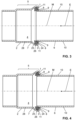
- eine Schnittansicht einer Ausführungsform einer erfindungsgemässen Anordnung mit einem Fitting, einem Dichtring und einem Rohrabschnitt im umgesteckten Zustand;
- Fig. 2
- eine weitere Schnittansicht nach
Figur 1 beim Vorgang des Einschiebens des Rohrabschnitts in den Fitting; - Fig. 3
- eine weitere Schnittansicht nach
Figur 1 beim Vorgang des Einschiebens des Rohrabschnitts in den Fitting; - Fig. 4
- eine weitere Schnittansicht nach
Figur 1 beim Vorgang des Einschiebens des Rohrabschnitts in den Fitting; - Fig. 5
- eine weitere Schnittansicht nach
Figur 1 beim Vorgang des Einschiebens des Rohrabschnitts in den Fitting; - Fig. 6
- eine weitere Schnittansicht nach
Figur 1 mit vollständig eingeschobenem Rohrabschnitt; - Fig. 7
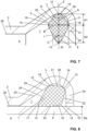
- eine detaillierte Schnittansicht des Dichtrings nach
Figur 1 ohne eingeschobenen Rohrabschnitt; - Fig. 8
- eine detaillierte Schnittansicht des Dichtrings nach
Figur 1 mit eingeschobenem Rohrabschnitt; - Fig. 9
- eine perspektivische Anordnung des Dichtrings gemäss den vorhergehenden Figuren;
- Fig. 10
- eine weitere perspektivische Anordnung des Dichtrings gemäss den vorhergehenden Figuren; und
- Fig. 11
- eine Detailansicht der Dichtrings gemäss den vorhergehenden
Figuren 1 . - In den Figuren wird eine Ausführungsform einer erfindungsgemässen Anordnung gezeigt. Die Anordnung umfasst einen Dichtring 1, einen Fitting 2 und ein Rohrabschnitt 6. Der Fitting 2 und der Rohrabschnitt 6 werden miteinander verbunden und mit dem Dichtrichtung 1 wird ein Spalt zwischen dem Fitting 2 und dem Rohrabschnitt 6 gedichtet. Der Fitting 2 wird nach der Verbindung verpresst.
- Der Dichtring 1 erstreckt sich um eine Mittelachse M herum. Die Mittelachse M verläuft dabei kollinear zur Mittelachse des Fittings 2 und des Rohrabschnitts 6.
- Der Fitting 2 kann verschiedenartig ausgebildet sein. Beispielsweise als Fitting zur Verbindung zweier kollinear verlaufenden Rohren oder als T-Stück. In den gezeigten Ausführungsformen ist der Fitting jeweils nur ausschnittsweise dargestellt. Der Fitting 2 weist eine Dichtringaufnahme 3, einen Aufnahmeraum 4 und eine Presszone 5 auf. Der Dichtring 1 wird in die Dichtringaufnahme 3 eingesetzt. Der Aufnahmeraum 4 dient der Aufnahme des Rohrabschnitts 6. Über die Presszone 5 kann von aussen her eine Verpresskraft auf den Fitting 2 ausgeübt werden, so dass der Fitting 2 gegen den Rohrabschnitt 6 gepresst wird. Die Presszone 5 erstreckt sich über die Dichtringaufnahme 3 und über einen sich der Dichtringaufnahme anschliessenden zylindrischen Bereich 28 des Fittings 2. Die Dichtringaufnahme 3 weist einen freien Raumbereich 7 auf. Der freie Raumbereich 7 liegt in einer Einschubrichtung E des Rohrabschnitts 6 gesehen, hinter dem Dichtring 1.
- Wie erwähnt ist der Fitting nur teilweise dargestellt. Der Fitting 2 kann sich gegenüber der Dichtringaufnahme 3 beliebig fortsetzen. Typischerweise weist der Fitting 2 noch weitere Aufnahmeräume und weitere Dichtringaufnahmen auf, so dass ein weiterer Rohrabschnitt oder weitere Rohrabschnitte mit dem Fitting 2 verbindbar sind.
- Ausgehend von der Position gemäss der
Figur 1 wir der Rohrabschnitt 6 entlang einer Einschubrichtung E in den Aufnahmeraum 4 des Fittings 2 eingeschoben. Die Einschubrichtung E ist dabei im Wesentlichen parallel zur Mittelachse M. Der Dichtring 1 ragt in seiner Ausgangslage, wie in derFigur 1 gezeigt, mit einem Kontaktabschnitt 8 radial aus der Dichtringaufnahme 3 in den Aufnahmeraum 4 hinein. Der Dichtring 1 ragt dabei soweit in den Aufnahmeraum 4 hinein, dass der Dichtring 1 im Bereich des Kontaktabschnitts 8 mit der Stirnseite des Rohrabschnitts 6, welches in den Aufnahmeraum 4 eingeschoben wird, in Kontakt kommt. Dieser Kontakt wird in derFigur 2 entsprechend dargestellt. Hier kann gut erkannt werden, dass die Stirnseite 9 des Rohrabschnitts 6 mit dem Kontaktabschnitt 8 in Kontakt kommt. Bei weiteren Einschieben des Rohrabschnitts 6 in den Aufnahmeraum 4 wird der Dichtring 1 von der in denFiguren 1 und 2 gezeigten Ausgangslage in eine Kipplage gekippt. - In den
Figuren 3 und 4 befindet sich der Dichtring 1 zwischen der Ausgangslage und der Kipplage. Je weiter der Rohrabschnitt 6 entlang der Einschubrichtung E in den Aufnahmeraum eingeschoben wird, desto weiter wird der Dichtring 1 gekippt. Der Dichtring 1 kippt dabei von der Ausgangslage derart, dass der Kontaktabschnitt 8 in Richtung des freien Raumbereich 7 bewegt wird. Dabei kommt der Kontaktabschnitt 8 mindestens teilweise in den freien Raumbereich 7 zu liegen. - In der
Figur 5 wird gezeigt, dass der Rohrabschnitt 6 schon soweit in den Aufnahmeraum 4 geschoben wurde, dass kein Kontakt mehr zwischen dem Kontaktabschnitt 8 und der Stirnseite 9 des Rohrabschnitts 6 vorhanden ist. Vielmehr liegt der Dichtring 1 mit dem Kontaktabschnitt 8 und einem Flächenbereich 11 auf der Aussenseite 10 des Rohrabschnitts 6 auf. In derFigur 6 befindet sich der Rohrabschnitt 6 in der vollständig eingeschobenen Lage. - Von der
Figur 6 kann gut erkannt werden, dass der Dichtring 1 in der Kipplage derart liegt, dass der Dichtring 1 bei einer Zugkraft entgegen der Einschubrichtung E auf den Rohrabschnitt 6 gegen die Aussenseite 10 des Rohrabschnitts 6 gedrückt wird. Der Dichtring 1 wirkt somit auch als Haltemittel zwischen dem Fitting 2 und dem Rohrabschnitt 6. Ein Herausziehen des Rohrabschnitts 6 entgegen der Einschubrichtung E wird somit erschwert. Das Herausziehen wird aber nicht verunmöglicht, denn bei einer genügend grossen Kraft wird der Dichtring 1 entsprechend elastisch verformt und zwischen der Aussenseite 10 des Rohrabschnitts 6 und der Innenseite 29 des Aufnahmeraums 4 komprimiert. Die Haltekraft hat den Vorteil, dass der Fitting 2 auf dem Rohrabschnitt 6 platziert werden kann und dann in seiner Lage gehalten wird bzw. dass der Rohrabschnitt 6 zum Fitting 2 gehalten wird. Insbesondere bei Überkopfmontagen ist dies von Vorteil. - Der Dichtring 1 weist, wie oben bereits erwähnt, einen Flächenbereich 11 auf. Der Flächenbereich 11 liegt in Ausgangslage derart in Inneren des Aufnahmeraums 4, dass die Stirnseite 9 des Rohrabschnitts 6 beim Einschieben nicht in Kontakt mit dem Flächenbereich 11 kommt. Dies wird in den
Figuren 1 und 2 gezeigt, wo der Flächenbereich 11 hinter einem ringflächigen Wandabschnitt 24 des Fittings liegt. Bei der Bewegung aus der Ausgangslage in die Kipplage wird der Flächenbereich 11 aus dem Inneren des Aufnahmeraums 4 aus dem Aufnahmeraum 4 hinaus zur Aussenseite des Rohrabschnitts 6 verschwenkt. In der Kipplage liegt der Flächenbereich 11 an der Aussenseite 10 des Rohrabschnitts 6 an. Diese Anordnung hat den Vorteil, dass ein Bereich des Dichtrings 1 mit der Aussenseite 10 in Kontakt kommt, welcher nicht mit der Stirnseite 9 des Rohrabschnitts in Kontakt gekommen ist. - Anhand der
Figuren 7 und 8 wird nun die spezifische und bevorzugte Ausführungsform des Querschnitts des Dichtrings 1 genauer erläutert. Der Dichtring 1 weist an seiner Aussenseite eine äussere Umfangslinie 12, eine innere Umfangslinie 13 und zwei seitliche Umfangslinien 14, 15 auf. Die äussere Umfangslinie 12 und die innere Umfangslinie 13 liegen in einer rechtwinklig zur Mittelachse M verlaufenden Ebene Z liegen. Die seitlichen Umfangslinien 14, 15 liegen in Richtung der Mittelachse M gesehen axial beabstandet zueinander. Die besagte Ebene Z liegt vorzugsweise mittig zwischen den beiden seitlichen Umfangslinien 14, 15. - Der radiale Abstand zwischen der äusseren Umfangslinie 12 und der inneren Umfangslinie 13 ist dabei grösser als der axiale Abstand zwischen den beiden seitlichen Umfangslinien 14, 15. Weiter liegen die seitlichen Umfangslinien 14, 15 bezüglich der Radialrichtung, die quer zur Mittelachse verläuft, näher bei der äusseren Umfangslinie 12 als bei der inneren Umfangslinie 13. In der Ausgangslage liegt die innere Umfangslinie 13 ausserhalb des Aufnahmeraums 4 und die seitlichen Umfangslinien 14, 15 sowie die äussere Umfangslinie 12 liegen im Inneren des Aufnahmeraums 4. In der Kipplage liegen eine der seitlichen Umfangslinien 14 und die innere Umfangslinie 13 ausserhalb des Aufnahmeraums 4 und eine der seitlichen Umfangslinien 15 sowie die äussere Umfangslinie 12 liegen im Inneren des Aufnahmeraums 4.
- Die Umfangslinien 12, 13, 14, 15 werden in der gezeigten Ausführungsform durch jeweils eine Scheitellinie einer konvexen Rundung 16, 17, 18, 19 gebildet.
- Der Dichtring weist aussenseitig weiter Flächenabschnitte 20, 21, 22, 23 auf. Jeweils ein Flächenabschnitt 20, 21, 22, 23 verbindet hier zwei benachbarte konvexe Rundungen 16, 17, 18, 19. In der gezeigten Ausführungsform erstrecken sich die Flächenabschnitte 20, 21, 22, 23 jeweils im Querschnitt durch die Mittelachse M gesehen als Gerade. Es wäre auch denkbar, dass die Flächenabschnitt 20, 21, 22, 23 konvex bombiert und konkav gerundet ausgebildet sind.
- Die beiden Flächenabschnitte, welche sich der konvexen Rundung 16 mit der äusseren Umfangslinie 12 anschliessen, schliessen im Querschnitt durch die Mittelachse M gesehen, einen Winkel α im Bereich von 55° bis 125°, insbesondere im Bereich von 70° und 100° oder von 80° bis 95°, ein.
- Die beiden Flächenabschnitte, welche sich der konvexen Rundung 17 mit der inneren Umfangslinie 13anschliessen, schliessen im Querschnitt durch die Mittelachse M gesehen, einen Winkel β im Bereich von 20° bis 85°, insbesondere im Bereich von 35° und 70° oder von 40° bis 65°, ein.
- Vorzugsweise sind die Winkel α und β nicht gleich, sondern unterschiedlich zueinander. Wie erwähnt liegen die seitlichen Umfangslinien näher zur äusseren Umfangslinie 12 als zur inneren Umfangslinie 13. Vorzugsweise liegt der Abstand A1 rechtwinklig zur Mittelachse M gesehen zwischen der äusseren Umfangslinie 12 und seitlichen Umfangslinie 14, 15 zwischen 30% und 48% des Abstandes A rechtwinklig zur Mittelachse M gesehen zwischen der äusseren Umfangslinie 12 und der inneren Umfangslinie 13. Demgemäss liegt der Abstand A2 rechtwinklig zur Mittelachse M gesehen zwischen der inneren Umfangslinie 13 und seitlichen Umfangslinie 14, 15 zwischen 52% und 70% des Abstandes A rechtwinklig zur Mittelachse M gesehen zwischen der äusseren Umfangslinie 12 und der inneren Umfangslinie 13.
- Der Abstand zwischen den beiden seitlichen Umfangslinien 14, 15 in Richtung der Mittelachse gesehen, trägt das Bezugszeichen B. Vorzugseise liegt der Abstand B zwischen 60% und 85% des Abstandes A.
- Bei einem Aussendurchmesser des Rohrabschnitts im Bereich von 12 bis 54 Millimeter, liegt der Abstand A im Bereich von 2.5 bis 7.5 Millimeter. Der Abstand A kann je nach Mass des Aussendurchmessers des Rohrabschnitts stetig oder Sprunghaft zunehmen. Der Abstand B liegt zwischen 2.0 und 5.0 Millimeter. Der Abstand B kann je nach Mass des Aussendurchmessers des Rohrabschnitts stetig oder Sprunghaft zunehmen.
- Von den
Figuren 7 und 8 ist weiter der Aufnahmeraum 4 ersichtlich. Der Aufnahmeraum 4 weist einen ringflächigen Wandabschnitt 24 auf, der sich vorzugsweise rechtwinklig zur Mittelachse M erstreckt. Von der Aussenseite des ringflächigen Wandabschnitts 24 erstreckt sich ein konischer Wandabschnitt 25 in Richtung der Mittelachse M derart, dass sich der Innendurchmesser des konischen Wandabschnitts 25 mit zunehmendem Abstand zum ringflächigen Wandabschnitt 24 verkleinert. Der oben erwähnte freie Raumbereich 7 liegt in dem Bereich des Aufnahmeraums 4, welcher durch den konischen Wandabschnitt 24 begrenzt ist. Der Übergang vom ringflächigen Wandabschnitt 24 zum konischen Wandabschnitt 25 ist hier als konkave Rundung 26 ausgebildet. - Der Aufnahmeraum 4 wird im verpressten Zustand so verkleinert, dass der Dichtring 1 an der Aussenseite 10 des Rohrabschnitts 6 über den gesamten Rohrumfang vollständig anliegt und dass der Dichtring 1 an der Innenseite des Aufnahmeraums 4 über den gesamten Umfang des Aufnahmeraums 4 anliegt.
- In der
Figur 7 ist weiterhin der Innendurchmesser Di des Dichtrings 1 eingezeichnet. Der Innendurchmesser Di des Dichtrings 1 ist in der Ausgangslage kleiner als der Aussendurchmesser Da des Rohrabschnitts 6. Der Aussendurchmesser Da ist in derFigur 8 eingezeichnet. - Der Fitting 2 weist in Einschubrichtung E gesehen vor dem Aufnahmeraum 4 einen Durchmesser auf, welcher leicht grösser ist als der Durchmesser nach dem Aufnahmeraum 4. Der Kontaktabschnitt 8 ist dabei der Abschnitt, welcher aus der Dichtringaufnahme 3 in den Aufnahmeraum 4 einragt. In der gezeigten Ausführungsform ist der Kontaktabschnitt 8 der Bereich des Dichtrings 1, welcher sich von der Mittelachse M gesehen auf den Durchmesser des Fittings 2 vor dem Aufnahmeraum 4 erstreckt. Mit anderen Worten gesagt ist der Kontaktabschnitt 8 der Bereich des Fittings, welcher in Richtung der Mittelachse M in Einschubrichtung E gesehen, sichtbar ist.
- In den
Figuren 9 und 10 wird der Dichtring perspektivisch gezeigt. Der Dichtring 1 weist in einer besonders bevorzugten Ausführung mindestens einen optionalen Durchgang 27 auf. Der Durchgang 27 stellt in der Kipplage einen durchlässigen Spalt auf der Aussenseite 10 des Rohrabschnitts 6 bereit, derart, dass bei einer nicht erfolgten Verpressung oder einer fehlerhaften Verpressung des Fittings 2 eine undichte Stelle vorhanden ist. Diese undichte Stelle trägt in derFigur 11 das Bezugszeichen 30. -
1 Dichtring 26 konkave Rundung 2 Fitting 27 Durchgang 3 Dichtringaufnahme 28 zylindrischer Bereich 4 Aufnahmeraum 29 Innenseite 5 Presszone 30 undichte Stelle 6 Rohrabschnitt 7 freier Raumbereich A Abstand 8 Kontaktabschnitt A1 Abstand 9 Stirnseite A2 Abstand 10 Aussenseite B Abstand 11 Flächenbereich E Einschubrichtung 12 äussere Umfangslinie M Mittelachse 13 innere Umfangslinie K Kipplinie 14 seitliche Umfangslinie Di Innendurchmesser Dichtring 15 seitliche Umfangslinie Da Aussendurchmesser Rohr 16 konvexe Rundung Z Ebene 17 konvexe Rundung α Winkel 18 konvexe Rundung β Winkel 19 konvexe Rundung 20 Flächenabschnitt 21 Flächenabschnitt 22 Flächenabschnitt 23 Flächenabschnitt 24 ringflächiger Wandabschnitt 25 konischer Wandabschnitt
Claims (13)
- Anordnung umfassendeinen Dichtring (1), der sich um eine Mittelachse (M) herum erstreckt,einen Fitting (2) mit einer Dichtringaufnahme (3), in welche der Dichtring (1) eingesetzt ist, einem Aufnahmeraum (4) und einer Presszone (5), welche mechanisch verpressbar ist, undeinen Rohrabschnitt (6), welcher entlang einer Einschubrichtung (E) in den Aufnahmeraum (4) des Fittings (2) einschiebbar ist,wobei die Dichtringaufnahme (3) in Einschubrichtung (E) hinter dem Dichtring gesehen einen freien Raumbereich (7) aufweist,wobei der Dichtring (1) mit einem Kontaktabschnitt (8) radial aus der Dichtringaufnahme (3) in den Aufnahmeraum (4) ragt, derart, dass die Stirnseite (9) des Rohrabschnitts (6) beim Einschieben des Rohrabschnitts (6) mit dem Kontaktabschnitt (8) in Kontakt bringbar ist, undwobei beim Einschieben des Rohrabschnitts (6) in Einschubrichtung (E) der Dichtring (1) von einer Ausgangslage in eine Kipplage kippt, derart, dass der Kontaktabschnitt (8) in Richtung des freien Raumbereichs (7) bewegbar ist und mindestens teilweise in den freien Raumbereich (7) zu liegen kommtwobei der Dichtring (1) eine äussere Umfangslinie (12), eine innere Umfangslinie (13) und zwei seitliche Umfangslinien (14, 15) aufweist, wobei die äussere Umfangslinie (12) und die innere Umfangslinie (13) in einer rechtwinklig zur Mittelachse verlaufenden Ebene (Z) liegen, wobei die seitlichen Umfangslinien (14, 15) in Richtung der Mittelachse (M) gesehen axial beabstandet zueinander liegen,dadurch gekennzeichnet dass die Dichtringaufnahme (3) einen ringflächigen Wandabschnitt (24) aufweist, der sich vorzugsweise rechtwinklig zur Mittelachse (M) erstreckt, wobei sich aussenseitig vom ringflächigen Wandabschnitt (24) ein konischer Wandabschnitt (25) derart in Richtung der Mittelachse (M) erstreckt, dass sich der Innendurchmesser des konischen Wandabschnitts (25) mit zunehmendem Abstand zum ringflächigen Wandabschnitt (24) verkleinert, und wobei der Übergang vom ringflächigen Wandabschnitt (24) zum konischen Wandabschnitt (25) als konkave Rundung (26) ausgebildet ist, undwobei der Dichtring (1) in der Ausgangslage mit einer seitlichen Umfangslinie (14) in Kontakt mit dem ringflächigen Wandabschnitt (24) und mit der äusseren Umfangslinie (12) in Kontakt mit dem konischen Wandabschnitt (25) oder mit der konkaven Rundung (26) ist.
- Anordnung nach Anspruch 1, dadurch gekennzeichnet, dass der Dichtring (1) in der Kipplage derart liegt, dass der Dichtring (1) bei einer Zugkraft entgegen der Einschubrichtung (E) auf den Rohrabschnitt (6) gegen die Aussenseite (10) des Rohrabschnitts (6) gedrückt wird, wodurch ein Herausziehen des Rohrabschnitts (6) entgegen der Einschubrichtung (E) erschwert ist.
- Anordnung nach Anspruch 1 oder 2, dadurch gekennzeichnet, dass der Innendurchmesser (Di) des Dichtrings (1) in der Ausgangslage kleiner als der Aussendurchmesser (Da) des Rohrabschnitts (6) ist.
- Anordnung nach einem der vorhergehenden Ansprüche, dadurch gekennzeichnet, dass der Dichtring (1) einen Flächenbereich (11) aufweist, welcher in der Ausgangslage im Inneren des Aufnahmeraums (4) liegt, derart, dass die Stirnseite (9) des Rohrabschnitts (6) beim Einschieben nicht in Kontakt mit dem Flächenbereich (11) kommt, und welcher bei der Bewegung aus der Ausgangslage in die Kipplage aus dem Inneren des Aufnahmeraums (4) aus dem Aufnahmeraum (4) zur Aussenseite (10) des Rohrabschnitts (6) verschwenkt wird.
- Anordnung nach einem der vorhergehenden Ansprüche, dadurch gekennzeichnet, dassdie besagte Ebene (Z) vorzugsweise mittig zwischen den beiden seitlichen Umfangslinien (14, 15) liegt.
- Anordnung nach Anspruch 5, dadurch gekennzeichnet, dass die Umfangslinien (12, 13, 14, 15) durch eine Scheitellinie einer jeweiligen konvexen Rundung (16, 17, 18, 19) der Aussenfläche des Dichtrings (1) gebildet werden.
- Anordnung nach Anspruch 5 oder 6, dadurch gekennzeichnet, dass der Dichtring aussenseitig Flächenabschnitte (20, 21, 22, 23) aufweist, wobei jeweils ein Flächenabschnitt (20, 21, 22, 23) zwei benachbarte Umfangslinien (12, 13, 14, 15) verbindet; oder Anordnung nach Anspruch 6, dadurch gekennzeichnet, dass der Dichtring aussenseitig Flächenabschnitte (20, 21, 22, 23) aufweist, wobei jeweils ein Flächenabschnitt (20, 21, 22, 23) zwei benachbarte konvexe Rundungen (16, 17, 18, 19) verbindet.
- Anordnung nach Anspruch 7, dadurch gekennzeichnet,dass die beiden Flächenabschnitte, welche sich der äusseren Umfangslinie (12) bzw. der konvexen Rundung (16) mit der äusseren Umfangslinie (12) anschliessen, im Querschnitt durch die Mittelachse (M) gesehen, einen Winkel (α) im Bereich von 55° bis 125°, insbesondere im Bereich von 70° und 100° oder im Bereich von 80° bis 95°, einschliessen; und/oderdass die beiden Flächenabschnitte, welche sich der inneren Umfangslinie (13) bzw. der konvexen Rundung (17) mit der inneren Umfangslinie (13) anschliessen, im Querschnitt durch die Mittelachse (M) gesehen, einen Winkel (β) im Bereich von 20° bis 85°, insbesondere im Bereich von 35° und 65°, einschliessen.
- Anordnung nach einem der vorhergehenden Ansprüche 5 bis 8, dadurch gekennzeichnet, dass ist der Dichtring (1) zur besagten Ebene (Z) symmetrisch ausgebildet ist.
- Anordnung nach einem der vorhergehenden Ansprüche, dadurch gekennzeichnet, dass der Dichtring (1) bei der Bewegung von der Ausgangslage in die Kipplage mit der seitlichen Umfangslinie (14) auf dem ringflächigen Wandabschnitt (24) zur Mittelachse (M) hin gleitet und dass das die äussere Umfangslinie (12) in Kontakt mit dem ringflächigen Wandabschnitt (24) kommt.
- Anordnung nach einem der vorhergehenden Ansprüche, dadurch gekennzeichnet, dass in der Kipplage die seitliche Umfangslinie (14), welche in der Ausgangslage in Kontakt mit dem ringflächigen Wandabschnitt (24) war, nicht in Kontakt mit dem ringflächigen Wandabschnitt (24) ist, dass die äussere Umfangslinie (12) in Kontakt mit dem ringflächigen Wandabschnitt (24) ist und dass die andere seitliche Umfangslinie (15) in Kontakt mit dem konischen Wandabschnitt (25) ist.
- Anordnung nach einem der vorhergehenden Ansprüche, dadurch gekennzeichnet, dass der Dichtring (1) mindestens einen Durchgang (27) aufweist, welcher in der Kipplage einen durchlässigen Spalt auf der Aussenseite (10) des Rohrabschnitts (6) und/oder der Innenseite der Dichtringaufnahme (3) bereitstellt, derart, dass bei einer nicht erfolgten Verpressung oder einer fehlerhaften Verpressung des Fittings (2) eine undichte Stelle vorhanden ist.
- Anordnung nach einem der vorhergehenden Ansprüche, dadurch gekennzeichnet, dass der Aufnahmeraum (4) im verpressten Zustand so verkleinert wird, dass der Dichtring (1) an der Aussenseite (10) des Rohrabschnitts (6) über den gesamten Rohrumfang vollständig anliegt und dass der Dichtring (1) an der Innenseite des Aufnahmeraums (4) über den gesamten Umfang des Aufnahmeraums (4) anliegt.
Priority Applications (1)
| Application Number | Priority Date | Filing Date | Title |
|---|---|---|---|
| EP21172128.7A EP4086494B1 (de) | 2021-05-04 | 2021-05-04 | Dichtringanordnung |
Applications Claiming Priority (1)
| Application Number | Priority Date | Filing Date | Title |
|---|---|---|---|
| EP21172128.7A EP4086494B1 (de) | 2021-05-04 | 2021-05-04 | Dichtringanordnung |
Publications (2)
| Publication Number | Publication Date |
|---|---|
| EP4086494A1 EP4086494A1 (de) | 2022-11-09 |
| EP4086494B1 true EP4086494B1 (de) | 2025-04-02 |
Family
ID=75825445
Family Applications (1)
| Application Number | Title | Priority Date | Filing Date |
|---|---|---|---|
| EP21172128.7A Active EP4086494B1 (de) | 2021-05-04 | 2021-05-04 | Dichtringanordnung |
Country Status (1)
| Country | Link |
|---|---|
| EP (1) | EP4086494B1 (de) |
Family Cites Families (4)
| Publication number | Priority date | Publication date | Assignee | Title |
|---|---|---|---|---|
| RU2072061C1 (ru) * | 1991-12-19 | 1997-01-20 | Дипп-Инж.Др.Эрнст Фогельзанг ГмбХ унд Ко., КГ | Трубный соединитель из муфты и вставной детали, в частности для пластмассовых труб |
| DE19840668C1 (de) * | 1998-08-26 | 1999-11-25 | Mannesmann Ag | Rohrverbindung |
| US9188260B2 (en) * | 2008-08-01 | 2015-11-17 | Nibco Inc. | Crimp evident seal |
| MY176920A (en) * | 2012-06-25 | 2020-08-26 | Kubota Kk | Sealing material, pressing ring, joint, and valve |
-
2021
- 2021-05-04 EP EP21172128.7A patent/EP4086494B1/de active Active
Also Published As
| Publication number | Publication date |
|---|---|
| EP4086494A1 (de) | 2022-11-09 |
Similar Documents
| Publication | Publication Date | Title |
|---|---|---|
| EP0159997B1 (de) | Kupplungsvorrichtung zur herstellung einer permanenten rohrverbindung | |
| DE1750220C3 (de) | Rohrkupplung | |
| EP2607768B1 (de) | Rohrklemme | |
| EP2607764B1 (de) | Rohrklemme mit Anschlussstück | |
| EP2924322B1 (de) | Dichtungsvorrichtung | |
| DE2609446A1 (de) | Kugelventil | |
| DE3428260A1 (de) | Rohrverbindung | |
| EP2278204B1 (de) | Wellrohranschlussverschraubung | |
| EP2837868A1 (de) | Baueinheit mit einem Rohr und einem Kupplungselement sowie Verfahren zur Herstellung einer derartigen Baueinheit | |
| EP0223185B1 (de) | Rohrkupplung | |
| EP3070385A1 (de) | Rohrverbindungssystem | |
| EP1924799B1 (de) | Anschlussstück für ein ende eines runden, insbesondere rohrförmigen gegenstandes | |
| EP2019246A2 (de) | Anordnung zur Befestigung einer Leitung mit einem profilierten Aussendurchmesser und Montageverfahren | |
| EP4086494B1 (de) | Dichtringanordnung | |
| DE102005061516A1 (de) | Fitting mit einem Dichtring | |
| EP2295842B1 (de) | Rohverbinder zum dichten Verbinden an ein Rohrende eines Rohres aus nachgiebigem Werkstoff | |
| WO2002070939A1 (de) | Dichtungsmanschette | |
| EP1548348B1 (de) | Dichtungsanordnung, insbesondere für einen Anschluss einer Leitung an einem Expansionsorgan | |
| DE20219600U1 (de) | Pressverbindungsanordnung und Halteelement für eine Pressverbindung | |
| DE102013201847B4 (de) | Abdichtung und Dichtring für eine Abdichtung | |
| EP4356035A1 (de) | Pressverbindungssystem zum unlösbaren verbinden eines fittings und fitting | |
| EP3324083B1 (de) | Dichtungsanordnung und deren verwendung | |
| EP3364088B1 (de) | Quetschkupplung zur verbindung eines schlauches mit einem rohrleitungsnippel | |
| EP2982894B1 (de) | Rohrklemmanordnung | |
| WO2000028250A1 (de) | Rohrpressverbindung |
Legal Events
| Date | Code | Title | Description |
|---|---|---|---|
| PUAI | Public reference made under article 153(3) epc to a published international application that has entered the european phase |
Free format text: ORIGINAL CODE: 0009012 |
|
| STAA | Information on the status of an ep patent application or granted ep patent |
Free format text: STATUS: THE APPLICATION HAS BEEN PUBLISHED |
|
| AK | Designated contracting states |
Kind code of ref document: A1 Designated state(s): AL AT BE BG CH CY CZ DE DK EE ES FI FR GB GR HR HU IE IS IT LI LT LU LV MC MK MT NL NO PL PT RO RS SE SI SK SM TR |
|
| STAA | Information on the status of an ep patent application or granted ep patent |
Free format text: STATUS: REQUEST FOR EXAMINATION WAS MADE |
|
| 17P | Request for examination filed |
Effective date: 20230322 |
|
| RBV | Designated contracting states (corrected) |
Designated state(s): AL AT BE BG CH CY CZ DE DK EE ES FI FR GB GR HR HU IE IS IT LI LT LU LV MC MK MT NL NO PL PT RO RS SE SI SK SM TR |
|
| GRAP | Despatch of communication of intention to grant a patent |
Free format text: ORIGINAL CODE: EPIDOSNIGR1 |
|
| STAA | Information on the status of an ep patent application or granted ep patent |
Free format text: STATUS: GRANT OF PATENT IS INTENDED |
|
| RIC1 | Information provided on ipc code assigned before grant |
Ipc: F16L 21/03 20060101ALI20231024BHEP Ipc: F16L 13/14 20060101AFI20231024BHEP |
|
| INTG | Intention to grant announced |
Effective date: 20231110 |
|
| GRAJ | Information related to disapproval of communication of intention to grant by the applicant or resumption of examination proceedings by the epo deleted |
Free format text: ORIGINAL CODE: EPIDOSDIGR1 |
|
| STAA | Information on the status of an ep patent application or granted ep patent |
Free format text: STATUS: REQUEST FOR EXAMINATION WAS MADE |
|
| STAA | Information on the status of an ep patent application or granted ep patent |
Free format text: STATUS: EXAMINATION IS IN PROGRESS |
|
| 17Q | First examination report despatched |
Effective date: 20240202 |
|
| INTC | Intention to grant announced (deleted) | ||
| RAP1 | Party data changed (applicant data changed or rights of an application transferred) |
Owner name: GEBERIT INTERNATIONAL AG |
|
| GRAP | Despatch of communication of intention to grant a patent |
Free format text: ORIGINAL CODE: EPIDOSNIGR1 |
|
| STAA | Information on the status of an ep patent application or granted ep patent |
Free format text: STATUS: GRANT OF PATENT IS INTENDED |
|
| INTG | Intention to grant announced |
Effective date: 20240917 |
|
| P01 | Opt-out of the competence of the unified patent court (upc) registered |
Free format text: CASE NUMBER: APP_58491/2024 Effective date: 20241025 |
|
| GRAJ | Information related to disapproval of communication of intention to grant by the applicant or resumption of examination proceedings by the epo deleted |
Free format text: ORIGINAL CODE: EPIDOSDIGR1 |
|
| STAA | Information on the status of an ep patent application or granted ep patent |
Free format text: STATUS: EXAMINATION IS IN PROGRESS |
|
| GRAP | Despatch of communication of intention to grant a patent |
Free format text: ORIGINAL CODE: EPIDOSNIGR1 |
|
| STAA | Information on the status of an ep patent application or granted ep patent |
Free format text: STATUS: GRANT OF PATENT IS INTENDED |
|
| INTC | Intention to grant announced (deleted) | ||
| GRAS | Grant fee paid |
Free format text: ORIGINAL CODE: EPIDOSNIGR3 |
|
| GRAA | (expected) grant |
Free format text: ORIGINAL CODE: 0009210 |
|
| STAA | Information on the status of an ep patent application or granted ep patent |
Free format text: STATUS: THE PATENT HAS BEEN GRANTED |
|
| INTG | Intention to grant announced |
Effective date: 20250129 |
|
| AK | Designated contracting states |
Kind code of ref document: B1 Designated state(s): AL AT BE BG CH CY CZ DE DK EE ES FI FR GB GR HR HU IE IS IT LI LT LU LV MC MK MT NL NO PL PT RO RS SE SI SK SM TR |
|
| REG | Reference to a national code |
Ref country code: GB Ref legal event code: FG4D Free format text: NOT ENGLISH |
|
| REG | Reference to a national code |
Ref country code: CH Ref legal event code: EP |
|
| REG | Reference to a national code |
Ref country code: DE Ref legal event code: R096 Ref document number: 502021007073 Country of ref document: DE |
|
| REG | Reference to a national code |
Ref country code: IE Ref legal event code: FG4D Free format text: LANGUAGE OF EP DOCUMENT: GERMAN |
|
| PGFP | Annual fee paid to national office [announced via postgrant information from national office to epo] |
Ref country code: DE Payment date: 20250521 Year of fee payment: 5 |
|
| PGFP | Annual fee paid to national office [announced via postgrant information from national office to epo] |
Ref country code: GB Payment date: 20250527 Year of fee payment: 5 |
|
| PGFP | Annual fee paid to national office [announced via postgrant information from national office to epo] |
Ref country code: FR Payment date: 20250530 Year of fee payment: 5 |
|
| PGFP | Annual fee paid to national office [announced via postgrant information from national office to epo] |
Ref country code: AT Payment date: 20250721 Year of fee payment: 5 |
|
| REG | Reference to a national code |
Ref country code: NL Ref legal event code: MP Effective date: 20250402 |
|
| PG25 | Lapsed in a contracting state [announced via postgrant information from national office to epo] |
Ref country code: NL Free format text: LAPSE BECAUSE OF FAILURE TO SUBMIT A TRANSLATION OF THE DESCRIPTION OR TO PAY THE FEE WITHIN THE PRESCRIBED TIME-LIMIT Effective date: 20250402 |
|
| PG25 | Lapsed in a contracting state [announced via postgrant information from national office to epo] |
Ref country code: FI Free format text: LAPSE BECAUSE OF FAILURE TO SUBMIT A TRANSLATION OF THE DESCRIPTION OR TO PAY THE FEE WITHIN THE PRESCRIBED TIME-LIMIT Effective date: 20250402 Ref country code: ES Free format text: LAPSE BECAUSE OF FAILURE TO SUBMIT A TRANSLATION OF THE DESCRIPTION OR TO PAY THE FEE WITHIN THE PRESCRIBED TIME-LIMIT Effective date: 20250402 Ref country code: PT Free format text: LAPSE BECAUSE OF FAILURE TO SUBMIT A TRANSLATION OF THE DESCRIPTION OR TO PAY THE FEE WITHIN THE PRESCRIBED TIME-LIMIT Effective date: 20250804 |
|
| REG | Reference to a national code |
Ref country code: LT Ref legal event code: MG9D |
|
| PG25 | Lapsed in a contracting state [announced via postgrant information from national office to epo] |
Ref country code: GR Free format text: LAPSE BECAUSE OF FAILURE TO SUBMIT A TRANSLATION OF THE DESCRIPTION OR TO PAY THE FEE WITHIN THE PRESCRIBED TIME-LIMIT Effective date: 20250703 Ref country code: NO Free format text: LAPSE BECAUSE OF FAILURE TO SUBMIT A TRANSLATION OF THE DESCRIPTION OR TO PAY THE FEE WITHIN THE PRESCRIBED TIME-LIMIT Effective date: 20250702 |
|
| PG25 | Lapsed in a contracting state [announced via postgrant information from national office to epo] |
Ref country code: PL Free format text: LAPSE BECAUSE OF FAILURE TO SUBMIT A TRANSLATION OF THE DESCRIPTION OR TO PAY THE FEE WITHIN THE PRESCRIBED TIME-LIMIT Effective date: 20250402 |
|
| PG25 | Lapsed in a contracting state [announced via postgrant information from national office to epo] |
Ref country code: BG Free format text: LAPSE BECAUSE OF FAILURE TO SUBMIT A TRANSLATION OF THE DESCRIPTION OR TO PAY THE FEE WITHIN THE PRESCRIBED TIME-LIMIT Effective date: 20250402 |
|
| PG25 | Lapsed in a contracting state [announced via postgrant information from national office to epo] |
Ref country code: HR Free format text: LAPSE BECAUSE OF FAILURE TO SUBMIT A TRANSLATION OF THE DESCRIPTION OR TO PAY THE FEE WITHIN THE PRESCRIBED TIME-LIMIT Effective date: 20250402 |
|
| PG25 | Lapsed in a contracting state [announced via postgrant information from national office to epo] |
Ref country code: RS Free format text: LAPSE BECAUSE OF FAILURE TO SUBMIT A TRANSLATION OF THE DESCRIPTION OR TO PAY THE FEE WITHIN THE PRESCRIBED TIME-LIMIT Effective date: 20250702 |
|
| PG25 | Lapsed in a contracting state [announced via postgrant information from national office to epo] |
Ref country code: IS Free format text: LAPSE BECAUSE OF FAILURE TO SUBMIT A TRANSLATION OF THE DESCRIPTION OR TO PAY THE FEE WITHIN THE PRESCRIBED TIME-LIMIT Effective date: 20250802 |
|
| PG25 | Lapsed in a contracting state [announced via postgrant information from national office to epo] |
Ref country code: LV Free format text: LAPSE BECAUSE OF FAILURE TO SUBMIT A TRANSLATION OF THE DESCRIPTION OR TO PAY THE FEE WITHIN THE PRESCRIBED TIME-LIMIT Effective date: 20250402 |
|
| REG | Reference to a national code |
Ref country code: CH Ref legal event code: H13 Free format text: ST27 STATUS EVENT CODE: U-0-0-H10-H13 (AS PROVIDED BY THE NATIONAL OFFICE) Effective date: 20251223 |
|
| REG | Reference to a national code |
Ref country code: DE Ref legal event code: R097 Ref document number: 502021007073 Country of ref document: DE |
|
| PG25 | Lapsed in a contracting state [announced via postgrant information from national office to epo] |
Ref country code: DK Free format text: LAPSE BECAUSE OF FAILURE TO SUBMIT A TRANSLATION OF THE DESCRIPTION OR TO PAY THE FEE WITHIN THE PRESCRIBED TIME-LIMIT Effective date: 20250402 Ref country code: SM Free format text: LAPSE BECAUSE OF FAILURE TO SUBMIT A TRANSLATION OF THE DESCRIPTION OR TO PAY THE FEE WITHIN THE PRESCRIBED TIME-LIMIT Effective date: 20250402 |
|
| PG25 | Lapsed in a contracting state [announced via postgrant information from national office to epo] |
Ref country code: LU Free format text: LAPSE BECAUSE OF NON-PAYMENT OF DUE FEES Effective date: 20250504 |
|
| PG25 | Lapsed in a contracting state [announced via postgrant information from national office to epo] |
Ref country code: CH Free format text: LAPSE BECAUSE OF NON-PAYMENT OF DUE FEES Effective date: 20250531 |
|
| PG25 | Lapsed in a contracting state [announced via postgrant information from national office to epo] |
Ref country code: CZ Free format text: LAPSE BECAUSE OF FAILURE TO SUBMIT A TRANSLATION OF THE DESCRIPTION OR TO PAY THE FEE WITHIN THE PRESCRIBED TIME-LIMIT Effective date: 20250402 |
|
| PG25 | Lapsed in a contracting state [announced via postgrant information from national office to epo] |
Ref country code: EE Free format text: LAPSE BECAUSE OF FAILURE TO SUBMIT A TRANSLATION OF THE DESCRIPTION OR TO PAY THE FEE WITHIN THE PRESCRIBED TIME-LIMIT Effective date: 20250402 |
|
| PG25 | Lapsed in a contracting state [announced via postgrant information from national office to epo] |
Ref country code: SK Free format text: LAPSE BECAUSE OF FAILURE TO SUBMIT A TRANSLATION OF THE DESCRIPTION OR TO PAY THE FEE WITHIN THE PRESCRIBED TIME-LIMIT Effective date: 20250402 |
|
| PG25 | Lapsed in a contracting state [announced via postgrant information from national office to epo] |
Ref country code: IT Free format text: LAPSE BECAUSE OF FAILURE TO SUBMIT A TRANSLATION OF THE DESCRIPTION OR TO PAY THE FEE WITHIN THE PRESCRIBED TIME-LIMIT Effective date: 20250402 |
|
| REG | Reference to a national code |
Ref country code: BE Ref legal event code: MM Effective date: 20250531 |
|
| PG25 | Lapsed in a contracting state [announced via postgrant information from national office to epo] |
Ref country code: MC Free format text: LAPSE BECAUSE OF FAILURE TO SUBMIT A TRANSLATION OF THE DESCRIPTION OR TO PAY THE FEE WITHIN THE PRESCRIBED TIME-LIMIT Effective date: 20250402 |
|
| PLBE | No opposition filed within time limit |
Free format text: ORIGINAL CODE: 0009261 |
|
| STAA | Information on the status of an ep patent application or granted ep patent |
Free format text: STATUS: NO OPPOSITION FILED WITHIN TIME LIMIT |
|
| PG25 | Lapsed in a contracting state [announced via postgrant information from national office to epo] |
Ref country code: RO Free format text: LAPSE BECAUSE OF FAILURE TO SUBMIT A TRANSLATION OF THE DESCRIPTION OR TO PAY THE FEE WITHIN THE PRESCRIBED TIME-LIMIT Effective date: 20250402 |
|
| REG | Reference to a national code |
Ref country code: CH Ref legal event code: L10 Free format text: ST27 STATUS EVENT CODE: U-0-0-L10-L00 (AS PROVIDED BY THE NATIONAL OFFICE) Effective date: 20260211 |
|
| 26N | No opposition filed |
Effective date: 20260105 |
|
| PG25 | Lapsed in a contracting state [announced via postgrant information from national office to epo] |
Ref country code: IE Free format text: LAPSE BECAUSE OF NON-PAYMENT OF DUE FEES Effective date: 20250504 |
|
| PG25 | Lapsed in a contracting state [announced via postgrant information from national office to epo] |
Ref country code: BE Free format text: LAPSE BECAUSE OF NON-PAYMENT OF DUE FEES Effective date: 20250531 |