EP4086500A1 - Support portatif pour treuil ou outils de traction - Google Patents
Support portatif pour treuil ou outils de traction Download PDFInfo
- Publication number
- EP4086500A1 EP4086500A1 EP22382091.1A EP22382091A EP4086500A1 EP 4086500 A1 EP4086500 A1 EP 4086500A1 EP 22382091 A EP22382091 A EP 22382091A EP 4086500 A1 EP4086500 A1 EP 4086500A1
- Authority
- EP
- European Patent Office
- Prior art keywords
- base
- column
- hoist
- support
- support according
- Prior art date
- Legal status (The legal status is an assumption and is not a legal conclusion. Google has not performed a legal analysis and makes no representation as to the accuracy of the status listed.)
- Granted
Links
Images




Classifications
-
- F—MECHANICAL ENGINEERING; LIGHTING; HEATING; WEAPONS; BLASTING
- F16—ENGINEERING ELEMENTS AND UNITS; GENERAL MEASURES FOR PRODUCING AND MAINTAINING EFFECTIVE FUNCTIONING OF MACHINES OR INSTALLATIONS; THERMAL INSULATION IN GENERAL
- F16M—FRAMES, CASINGS OR BEDS OF ENGINES, MACHINES OR APPARATUS, NOT SPECIFIC TO ENGINES, MACHINES OR APPARATUS PROVIDED FOR ELSEWHERE; STANDS; SUPPORTS
- F16M11/00—Stands or trestles as supports for apparatus or articles placed thereon ; Stands for scientific apparatus such as gravitational force meters
- F16M11/42—Stands or trestles as supports for apparatus or articles placed thereon ; Stands for scientific apparatus such as gravitational force meters with arrangement for propelling the support stands on wheels
-
- B—PERFORMING OPERATIONS; TRANSPORTING
- B21—MECHANICAL METAL-WORKING WITHOUT ESSENTIALLY REMOVING MATERIAL; PUNCHING METAL
- B21D—WORKING OR PROCESSING OF SHEET METAL OR METAL TUBES, RODS OR PROFILES WITHOUT ESSENTIALLY REMOVING MATERIAL; PUNCHING METAL
- B21D1/00—Straightening, restoring form or removing local distortions of sheet metal or specific articles made therefrom; Stretching sheet metal combined with rolling
- B21D1/14—Straightening frame structures
-
- B—PERFORMING OPERATIONS; TRANSPORTING
- B21—MECHANICAL METAL-WORKING WITHOUT ESSENTIALLY REMOVING MATERIAL; PUNCHING METAL
- B21D—WORKING OR PROCESSING OF SHEET METAL OR METAL TUBES, RODS OR PROFILES WITHOUT ESSENTIALLY REMOVING MATERIAL; PUNCHING METAL
- B21D1/00—Straightening, restoring form or removing local distortions of sheet metal or specific articles made therefrom; Stretching sheet metal combined with rolling
- B21D1/12—Straightening vehicle body parts or bodies
-
- F—MECHANICAL ENGINEERING; LIGHTING; HEATING; WEAPONS; BLASTING
- F16—ENGINEERING ELEMENTS AND UNITS; GENERAL MEASURES FOR PRODUCING AND MAINTAINING EFFECTIVE FUNCTIONING OF MACHINES OR INSTALLATIONS; THERMAL INSULATION IN GENERAL
- F16M—FRAMES, CASINGS OR BEDS OF ENGINES, MACHINES OR APPARATUS, NOT SPECIFIC TO ENGINES, MACHINES OR APPARATUS PROVIDED FOR ELSEWHERE; STANDS; SUPPORTS
- F16M11/00—Stands or trestles as supports for apparatus or articles placed thereon ; Stands for scientific apparatus such as gravitational force meters
- F16M11/20—Undercarriages with or without wheels
- F16M11/2007—Undercarriages with or without wheels comprising means allowing pivoting adjustment
- F16M11/2021—Undercarriages with or without wheels comprising means allowing pivoting adjustment around a horizontal axis
-
- F—MECHANICAL ENGINEERING; LIGHTING; HEATING; WEAPONS; BLASTING
- F16—ENGINEERING ELEMENTS AND UNITS; GENERAL MEASURES FOR PRODUCING AND MAINTAINING EFFECTIVE FUNCTIONING OF MACHINES OR INSTALLATIONS; THERMAL INSULATION IN GENERAL
- F16M—FRAMES, CASINGS OR BEDS OF ENGINES, MACHINES OR APPARATUS, NOT SPECIFIC TO ENGINES, MACHINES OR APPARATUS PROVIDED FOR ELSEWHERE; STANDS; SUPPORTS
- F16M11/00—Stands or trestles as supports for apparatus or articles placed thereon ; Stands for scientific apparatus such as gravitational force meters
- F16M11/20—Undercarriages with or without wheels
- F16M11/24—Undercarriages with or without wheels changeable in height or length of legs, also for transport only, e.g. by means of tubes screwed into each other
-
- F—MECHANICAL ENGINEERING; LIGHTING; HEATING; WEAPONS; BLASTING
- F16—ENGINEERING ELEMENTS AND UNITS; GENERAL MEASURES FOR PRODUCING AND MAINTAINING EFFECTIVE FUNCTIONING OF MACHINES OR INSTALLATIONS; THERMAL INSULATION IN GENERAL
- F16M—FRAMES, CASINGS OR BEDS OF ENGINES, MACHINES OR APPARATUS, NOT SPECIFIC TO ENGINES, MACHINES OR APPARATUS PROVIDED FOR ELSEWHERE; STANDS; SUPPORTS
- F16M2200/00—Details of stands or supports
- F16M2200/08—Foot or support base
Definitions
- the present invention relates to a support device for hoist or traction tools, for example, those used in automotive workshops, which is designed in a portable manner for it to be easily moved and located within the workshop.
- Supports for hoist or traction tools are known, of those used, for example, in automotive workshops, which include a base on which a vertical column is fastened to which a hoist or traction tool to be used is coupled.
- the base can comprise one or more heavy elements, which keep the support device immobile on a support surface, for example, the floor of a workshop, while the hoist or traction tool is actuated, for example, to pull a heavy part or element towards the support device.
- the present invention is a portable support for hoist or traction tools.
- the mobile support comprises:
- the support comprises a flexible perimeter rim fastened and extending from a second surface of the base, in such a way that, during the use of the support, said flexible perimeter rim is arranged between the base and the support surface, forming a closed space.
- the base is supported on the support surface, for example, the floor of a workshop, by means of the flexible perimeter rim, which acts as a seal or joint between the base and the support surface, forming the closed space.
- the support additionally comprises a vacuum generating means in fluid communication with the closed space formed, by means of a vacuum line or pipe that is connected to a perforation in the base, such that a vacuum or negative pressure generated by the vacuum generating means creates such a depression or reduction of pressure inside the closed space that it produces a rigid fastening of the base to the support surface, suitable for actuating the hoist or traction tool coupled to the column of the support.
- a vacuum generating means in fluid communication with the closed space formed, by means of a vacuum line or pipe that is connected to a perforation in the base, such that a vacuum or negative pressure generated by the vacuum generating means creates such a depression or reduction of pressure inside the closed space that it produces a rigid fastening of the base to the support surface, suitable for actuating the hoist or traction tool coupled to the column of the support.
- the vacuum generating means could be configured to create a vacuum pressure of 88 kPa in the closed space formed between the base and the support surface, such that the fastening achieved between such base and support surface supports a maximum traction force of the hoist or traction tool of 2500 Kg, achieving more than enough traction capacity for, for example, repair tasks in an automotive workshop that require it.
- a portable support for hoist or traction tools which can be easily moved and located in the required place with the simple actuation of the vacuum generating means, which allows the base to be very easily fastened rigidly to the support surface with the actuation of the vacuum generating means, or, such base can be easily decoupled from the support surface when said vacuum generating means is no longer activated, with a view to moving and locating the support in another place where the support is required to be relocated.
- the present invention refers to a portable support for hoist or traction tools, for example, those used in automotive workshops.
- the device comprises:
- said base (1) and column (2) can be made of aluminium or steel.
- the third end (2.1) of the column (2) is fastened to the first surface (1.1) of the base (1) by means of plates (10) fastened longitudinally to the base (1).
- the plates (10) are arranged parallel to each other and extended perpendicularly to a longitudinal plane of the base (1), such that the column (2) is adapted to fit between the plates (10) and to be fastened to them through known removable fastening means (not shown in the figures), such as a screw-nut assembly or the like, which are adapted to pass through first (2.11) and third holes (10.1) of the third end (2.1) of the column (2) and of the plates (10) respectively.
- the plates (10) comprise respective rows of fourth holes (10.2), so that a fastening position of the column (2) can be varied with respect to the base (1), as required.
- the column (2) is configured such that a hoist or traction tool (4) can be coupled to it by means of second fastening means (not shown in the figures) of a coupling part (12) of the hoist or traction tool (4), said second fastening means being of any known type that allow them to be placed at a certain height of the column (2), convenient for the correct operation of the hoist or traction tool (4).
- the column (2) could comprise a row of second holes (2.3) adapted to be passed through by the second fastening means, which could be, for example, a screw-nut assembly or the like.
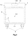
- the support comprises a flexible perimeter rim (9), for example, made of rubber or similar material, fastened and extended from a second surface (1.2) of the base (1).
- the first and second surfaces (1.1, 1.2) are the largest opposite surfaces of the base (1).
- said flexible perimeter rim (9) is arranged between the base (1) and the support surface (3), forming a closed space (6) between said elements (1, 9, 3).
- the support surface (3) is a flat surface, without scratches or cracks, as well as free of dirt and dust.
- it could be the floor of a workshop that meets such conditions.
- the support comprises a vacuum generating means (5), for example, as shown in Figure 3 , a vacuum ejector (5.1), in fluid communication with the closed space (6) by means of a vacuum line or pipe (7) that is connected to a perforation (1.3) of the base (1), such that a vacuum generated by the vacuum generating means (5) produces the rigid fastening of the base (1) to the support surface (3).
- a vacuum generating means (5) for example, as shown in Figure 3 , a vacuum ejector (5.1), in fluid communication with the closed space (6) by means of a vacuum line or pipe (7) that is connected to a perforation (1.3) of the base (1), such that a vacuum generated by the vacuum generating means (5) produces the rigid fastening of the base (1) to the support surface (3).
- the vacuum ejector (5.1) is fed by a stream of pressurised air (A), and at its outlet, comprises a silencer (14), such that said stream of pressurised air (A), due to the "Venturi” effect caused inside the vacuum ejector (5.1), creates such depression or vacuum pressure in the closed space (6) that it produces the rigid fastening of the base (1) to the support surface (3).
- the vacuum generating means (5) could be fastened to the base (1) or to the column (2). Likewise, it can be of any known type, such as a vacuum compressor or vacuum pump with 220 V electrical drive.
- the latter is designed with a vacuum generating means (5) adapted to create a vacuum pressure of 88 kPa in the closed space (6), where said vacuum pressure value corresponds to a maximum traction force of the hoist or traction tool (4) of 2500 Kg, which is more than enough, for example, for repair work carried out in an automotive workshop that requires the use of a hoist or traction tool (4).
- a vacuum generating means (5) adapted to create a vacuum pressure of 88 kPa in the closed space (6), where said vacuum pressure value corresponds to a maximum traction force of the hoist or traction tool (4) of 2500 Kg, which is more than enough, for example, for repair work carried out in an automotive workshop that requires the use of a hoist or traction tool (4).
- supports according to the present invention could be designed with greater capacity to withstand higher traction forces.
- a support for hoist or traction tools (4) that is portable and as effective as known supports, which require moving heavy weights to move them.
- the support of the present invention can be easily moved and located from one place to another as required. Its operation is based on the simple actuation of the vacuum generating means (5) with the stream of pressurised air (A), when the base (1) is required to be rigidly fastened to the support surface (3), in such a way that it allows to support the traction force exerted by the hoist or traction tool (4) during its use; and then, when the support is to be moved to another place where it is to be relocated, the base (1) can be easily uncoupled from the support surface (3), by simply stopping activating the vacuum generating means (5).
- the support may comprise wheels (8) arranged at a first end (1.4) of the base (1).
- the wheels (8) are arranged perpendicular to a longitudinal plane of the base (1).
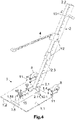
- the wheels (8) could be fastened to the first surface (1.1) of the base (1) by means of respective flat plates (11), or with an "L" profile (embodiment not shown in the figures), for example, welded at one of its ends to said first surface (1.1) of the base (1), or as an extension of the base (1), Figures 4 and 5 .
- a fourth end (2.2) of the column (2) could comprise handles (13), for example, arranged on the respective sides of the column (2).
- a user who wishes to move the support from one location to another simply positions himself in front of the support, on the side of the first end (1.4) of its base (1), and pulls on the handles (13) towards himself, so that it pivots the base (1) of the support on the wheels (8), and with this, the support is free for easy movement.
- a second end (1.5) of the base (1) could be designed comprising an oblong hole (1.51) as a gripper, so that, by hoist said gripper, the user can easily uncouple the base (1) from the support surface (3), when the vacuum generating means (5) is no longer actuated, for example, to then pull on the handles (13) with less effort, and achieve movement of the support.
- the hoist or traction tool (4) can be a flexible element, such as the chain of Figures 1 , 4 and 5 or any other flexible element -cable, rope, etc.- as shown generically in Figures 6A to 6E , a return pulley (15) is arranged between two facing fourth holes (10.2) on respective plates (10), four in the embodiments of Figures 1 , 4 , 5 , 6A to 6E , so that a position of the return pulley (15) can be varied with respect to the base (1), by simply arranging it in one or other facing fourth holes (10.2), the hoist or traction tool (4) passes between the return pulley (15) and the base (1) towards the outside of the support, as can be seen in Figures 6A to 6C .
- the free end of the hoist or traction tool (4) acquires the desired direction.
- this is especially significant given that the sheet metal of a vehicle acquires different orientations and curvatures that make it necessary to adapt to them and in each case the pull direction to proceed with the sheet metal repair, usually to repair different dents.
- the third holes (10.1) serve to fasten the column (2) between the plates (10).
- This is not represented in the figures for when the column (2) is arranged perpendicular or angled with respect to the base (1); it is represented in Figure 6D when it is arranged parallel with respect to the base (1).
- the hoist or traction tool (4) has been partially represented in the possible orientations of the other Figures 6A to 6C and 6E which are discussed below.
- Figure 6E shows the option where the column (2) is arranged parallel with respect to the base (1), the hoist or traction tool (4) is a flexible element, a directing element (16) is arranged between two facing fourth holes (10.2) of the respective plates (10), so that a position of the directing element (16) can be varied with respect to the base (1), the hoist or traction tool (4) passes over said directing element (16) to change its direction.
- a directing element (16) is arranged between two facing fourth holes (10.2) of the respective plates (10)
- the option where the column (2) is arranged parallel to the base (1) has the added advantage of making the support be approximately in the same plane, which facilitates its storage.
- two supports can be located on opposite sides of the workpiece to exert a pull and have an opposing or counter-hoist resistant element, this is sometimes done on opposite sides of a vehicle body.
- the support surface (3) or floor on which the support is arranged is more or less horizontal.
- said support surface (3) could have any orientation or even be vertical, like the wall of a workshop, and the support shown here would be equally valid and operate in the manner explained here, highlighting that it may even be advantageous to obtain different directions, and resulting pull forces of the hoist or traction tool (4).
Landscapes
- Engineering & Computer Science (AREA)
- Mechanical Engineering (AREA)
- General Engineering & Computer Science (AREA)
- Handcart (AREA)
- Forklifts And Lifting Vehicles (AREA)
- Jib Cranes (AREA)
- Hooks, Suction Cups, And Attachment By Adhesive Means (AREA)
- Portable Nailing Machines And Staplers (AREA)
- Load-Engaging Elements For Cranes (AREA)
Applications Claiming Priority (1)
| Application Number | Priority Date | Filing Date | Title |
|---|---|---|---|
| ES202130398A ES2927788B2 (es) | 2021-05-05 | 2021-05-05 | Soporte portatil para herramientas de tiro o traccion |
Publications (2)
| Publication Number | Publication Date |
|---|---|
| EP4086500A1 true EP4086500A1 (fr) | 2022-11-09 |
| EP4086500B1 EP4086500B1 (fr) | 2023-12-20 |
Family
ID=80682405
Family Applications (1)
| Application Number | Title | Priority Date | Filing Date |
|---|---|---|---|
| EP22382091.1A Active EP4086500B1 (fr) | 2021-05-05 | 2022-02-03 | Support portatif pour treuil ou outils de traction |
Country Status (6)
| Country | Link |
|---|---|
| EP (1) | EP4086500B1 (fr) |
| DE (1) | DE202022103930U1 (fr) |
| DK (1) | DK4086500T3 (fr) |
| ES (2) | ES2927788B2 (fr) |
| PL (1) | PL4086500T3 (fr) |
| PT (1) | PT4086500T (fr) |
Cited By (4)
| Publication number | Priority date | Publication date | Assignee | Title |
|---|---|---|---|---|
| IT202200025695A1 (it) * | 2022-12-15 | 2024-06-15 | Prima Srl | Dispositivo di trazione con dispositivo di aspirazione a batteria |
| FR3145103A1 (fr) * | 2023-01-25 | 2024-07-26 | Gys | Dispositif de redressement de tole |
| AU2025220780B1 (en) * | 2024-04-18 | 2025-10-02 | Clem Cuschieri | Vacuum dent pulling tower |
| WO2025217670A1 (fr) * | 2024-04-18 | 2025-10-23 | Clem Cuschieri | Tour de traction d'indentation vide |
Families Citing this family (1)
| Publication number | Priority date | Publication date | Assignee | Title |
|---|---|---|---|---|
| WO2024095102A1 (fr) * | 2022-11-04 | 2024-05-10 | Prima Srl | Dispositif de traction |
Citations (1)
| Publication number | Priority date | Publication date | Assignee | Title |
|---|---|---|---|---|
| FR2110281A1 (fr) * | 1970-10-07 | 1972-06-02 | Wolgast Raymond |
Family Cites Families (7)
| Publication number | Priority date | Publication date | Assignee | Title |
|---|---|---|---|---|
| US4475716A (en) * | 1982-09-28 | 1984-10-09 | Jarmin Davis R | Height adjustable tower mounted pull assembly |
| US4658628A (en) * | 1985-03-29 | 1987-04-21 | Grace William G | Vehicle frame straightening apparatus |
| US4720991A (en) * | 1986-11-03 | 1988-01-26 | Kuhn Manufacturing Co., Inc. | Single anchor secondary safety tie down for a pulling apparatus |
| US4748842A (en) * | 1986-11-28 | 1988-06-07 | Dingman Boyd W | Sheet metal pulling apparatus |
| FR2626790B1 (fr) * | 1988-02-10 | 1994-05-20 | Sefac | Equerre de traction adaptable a un marbre, pour le montage, le controle et la reparation des carrosseries de vehicules automobiles |
| US7269990B1 (en) * | 2005-04-07 | 2007-09-18 | Michael Espinosa And King's Products, Inc. | Portable frame puller |
| WO2017171711A1 (fr) * | 2016-03-28 | 2017-10-05 | Orlando Ceballos | Système pneumohydraulique pour la réparation de conteneurs de transport |
-
2021
- 2021-05-05 ES ES202130398A patent/ES2927788B2/es active Active
-
2022
- 2022-02-03 DK DK22382091.1T patent/DK4086500T3/da active
- 2022-02-03 EP EP22382091.1A patent/EP4086500B1/fr active Active
- 2022-02-03 PT PT223820911T patent/PT4086500T/pt unknown
- 2022-02-03 PL PL22382091.1T patent/PL4086500T3/pl unknown
- 2022-02-03 DE DE202022103930.5U patent/DE202022103930U1/de active Active
- 2022-02-03 ES ES22382091T patent/ES2969647T3/es active Active
Patent Citations (1)
| Publication number | Priority date | Publication date | Assignee | Title |
|---|---|---|---|---|
| FR2110281A1 (fr) * | 1970-10-07 | 1972-06-02 | Wolgast Raymond |
Cited By (5)
| Publication number | Priority date | Publication date | Assignee | Title |
|---|---|---|---|---|
| IT202200025695A1 (it) * | 2022-12-15 | 2024-06-15 | Prima Srl | Dispositivo di trazione con dispositivo di aspirazione a batteria |
| FR3145103A1 (fr) * | 2023-01-25 | 2024-07-26 | Gys | Dispositif de redressement de tole |
| EP4406673A1 (fr) * | 2023-01-25 | 2024-07-31 | Gys | Dispositif de redressement de tole |
| AU2025220780B1 (en) * | 2024-04-18 | 2025-10-02 | Clem Cuschieri | Vacuum dent pulling tower |
| WO2025217670A1 (fr) * | 2024-04-18 | 2025-10-23 | Clem Cuschieri | Tour de traction d'indentation vide |
Also Published As
| Publication number | Publication date |
|---|---|
| ES2927788A1 (es) | 2022-11-10 |
| EP4086500B1 (fr) | 2023-12-20 |
| ES2927788B2 (es) | 2023-03-15 |
| DK4086500T3 (da) | 2024-02-19 |
| DE202022103930U1 (de) | 2022-08-29 |
| PL4086500T3 (pl) | 2024-07-01 |
| ES2969647T3 (es) | 2024-05-21 |
| ES2927788B4 (es) | 2024-07-09 |
| PT4086500T (pt) | 2024-01-29 |
Similar Documents
| Publication | Publication Date | Title |
|---|---|---|
| EP4086500A1 (fr) | Support portatif pour treuil ou outils de traction | |
| US3340720A (en) | Automobile repair tool | |
| US8240682B2 (en) | Jackhammer trolley | |
| CN110886498B (zh) | 一种装配式建筑预制钢结构连接定位机械及施工方法 | |
| US4753104A (en) | Dent removing tool and method | |
| US7900420B2 (en) | Hammer drill attachment and method | |
| US20070177943A1 (en) | Jack for carrying and installing mine panels | |
| US3584836A (en) | Portable force applicator | |
| US3728891A (en) | Vacuum cup | |
| US20060151252A1 (en) | Heavy duty vehicle component lift apparatus and method | |
| US20180304452A1 (en) | Combination Sheet Metal Hammer and Duct Stretcher Device | |
| US3902605A (en) | Suction lifting apparatus | |
| US4057994A (en) | Automobile body pulling tool | |
| CN222807068U (zh) | 一种悬挂式助力机械手 | |
| JPH10250535A (ja) | 板金加工具 | |
| CN214348316U (zh) | 清洁装置 | |
| CN217675514U (zh) | 工件卡爪及上下料装置 | |
| JP3213512U (ja) | エアパレット搬送用接続治具及びエアパレット搬送装置 | |
| CN115057151A (zh) | 物项运输装置及工装 | |
| CN215316142U (zh) | 一种模治具加工用台式攻牙机 | |
| JP3164550B2 (ja) | ドリル補助具 | |
| CN216104857U (zh) | 基于空调底盘组件加工用的码放设备 | |
| CN223070826U (zh) | 一种用于电动车防撞管加工的定位夹具 | |
| MXPA05009131A (es) | Banco de rectificacion de la carroceria del coche. | |
| CN111958541B (zh) | 一种便携式气瓶胶圈装卸工具 |
Legal Events
| Date | Code | Title | Description |
|---|---|---|---|
| PUAI | Public reference made under article 153(3) epc to a published international application that has entered the european phase |
Free format text: ORIGINAL CODE: 0009012 |
|
| STAA | Information on the status of an ep patent application or granted ep patent |
Free format text: STATUS: THE APPLICATION HAS BEEN PUBLISHED |
|
| AK | Designated contracting states |
Kind code of ref document: A1 Designated state(s): AL AT BE BG CH CY CZ DE DK EE ES FI FR GB GR HR HU IE IS IT LI LT LU LV MC MK MT NL NO PL PT RO RS SE SI SK SM TR |
|
| STAA | Information on the status of an ep patent application or granted ep patent |
Free format text: STATUS: REQUEST FOR EXAMINATION WAS MADE |
|
| RBV | Designated contracting states (corrected) |
Designated state(s): AL AT BE BG CH CY CZ DE DK EE ES FI FR GB GR HR HU IE IS IT LI LT LU LV MC MK MT NL NO PL PT RO RS SE SI SK SM TR |
|
| 17P | Request for examination filed |
Effective date: 20221117 |
|
| STAA | Information on the status of an ep patent application or granted ep patent |
Free format text: STATUS: EXAMINATION IS IN PROGRESS |
|
| 17Q | First examination report despatched |
Effective date: 20230125 |
|
| TPAC | Observations filed by third parties |
Free format text: ORIGINAL CODE: EPIDOSNTIPA |
|
| GRAP | Despatch of communication of intention to grant a patent |
Free format text: ORIGINAL CODE: EPIDOSNIGR1 |
|
| STAA | Information on the status of an ep patent application or granted ep patent |
Free format text: STATUS: GRANT OF PATENT IS INTENDED |
|
| GRAS | Grant fee paid |
Free format text: ORIGINAL CODE: EPIDOSNIGR3 |
|
| GRAA | (expected) grant |
Free format text: ORIGINAL CODE: 0009210 |
|
| STAA | Information on the status of an ep patent application or granted ep patent |
Free format text: STATUS: THE PATENT HAS BEEN GRANTED |
|
| INTG | Intention to grant announced |
Effective date: 20231026 |
|
| AK | Designated contracting states |
Kind code of ref document: B1 Designated state(s): AL AT BE BG CH CY CZ DE DK EE ES FI FR GB GR HR HU IE IS IT LI LT LU LV MC MK MT NL NO PL PT RO RS SE SI SK SM TR |
|
| REG | Reference to a national code |
Ref country code: GB Ref legal event code: FG4D |
|
| REG | Reference to a national code |
Ref country code: CH Ref legal event code: EP |
|
| REG | Reference to a national code |
Ref country code: DE Ref legal event code: R096 Ref document number: 602022001398 Country of ref document: DE |
|
| REG | Reference to a national code |
Ref country code: IE Ref legal event code: FG4D |
|
| REG | Reference to a national code |
Ref country code: PT Ref legal event code: SC4A Ref document number: 4086500 Country of ref document: PT Date of ref document: 20240129 Kind code of ref document: T Free format text: AVAILABILITY OF NATIONAL TRANSLATION Effective date: 20240123 |
|
| REG | Reference to a national code |
Ref country code: DK Ref legal event code: T3 Effective date: 20240213 Ref country code: NO Ref legal event code: T2 Effective date: 20231220 |
|
| REG | Reference to a national code |
Ref country code: SE Ref legal event code: TRGR |
|
| PG25 | Lapsed in a contracting state [announced via postgrant information from national office to epo] |
Ref country code: GR Free format text: LAPSE BECAUSE OF FAILURE TO SUBMIT A TRANSLATION OF THE DESCRIPTION OR TO PAY THE FEE WITHIN THE PRESCRIBED TIME-LIMIT Effective date: 20240321 |
|
| REG | Reference to a national code |
Ref country code: LT Ref legal event code: MG9D |
|
| PG25 | Lapsed in a contracting state [announced via postgrant information from national office to epo] |
Ref country code: LT Free format text: LAPSE BECAUSE OF FAILURE TO SUBMIT A TRANSLATION OF THE DESCRIPTION OR TO PAY THE FEE WITHIN THE PRESCRIBED TIME-LIMIT Effective date: 20231220 |
|
| REG | Reference to a national code |
Ref country code: NL Ref legal event code: MP Effective date: 20231220 |
|
| PG25 | Lapsed in a contracting state [announced via postgrant information from national office to epo] |
Ref country code: LT Free format text: LAPSE BECAUSE OF FAILURE TO SUBMIT A TRANSLATION OF THE DESCRIPTION OR TO PAY THE FEE WITHIN THE PRESCRIBED TIME-LIMIT Effective date: 20231220 Ref country code: GR Free format text: LAPSE BECAUSE OF FAILURE TO SUBMIT A TRANSLATION OF THE DESCRIPTION OR TO PAY THE FEE WITHIN THE PRESCRIBED TIME-LIMIT Effective date: 20240321 Ref country code: FI Free format text: LAPSE BECAUSE OF FAILURE TO SUBMIT A TRANSLATION OF THE DESCRIPTION OR TO PAY THE FEE WITHIN THE PRESCRIBED TIME-LIMIT Effective date: 20231220 Ref country code: BG Free format text: LAPSE BECAUSE OF FAILURE TO SUBMIT A TRANSLATION OF THE DESCRIPTION OR TO PAY THE FEE WITHIN THE PRESCRIBED TIME-LIMIT Effective date: 20240320 |
|
| PG25 | Lapsed in a contracting state [announced via postgrant information from national office to epo] |
Ref country code: NL Free format text: LAPSE BECAUSE OF FAILURE TO SUBMIT A TRANSLATION OF THE DESCRIPTION OR TO PAY THE FEE WITHIN THE PRESCRIBED TIME-LIMIT Effective date: 20231220 |
|
| REG | Reference to a national code |
Ref country code: ES Ref legal event code: FG2A Ref document number: 2969647 Country of ref document: ES Kind code of ref document: T3 Effective date: 20240521 |
|
| PG25 | Lapsed in a contracting state [announced via postgrant information from national office to epo] |
Ref country code: RS Free format text: LAPSE BECAUSE OF FAILURE TO SUBMIT A TRANSLATION OF THE DESCRIPTION OR TO PAY THE FEE WITHIN THE PRESCRIBED TIME-LIMIT Effective date: 20231220 Ref country code: NL Free format text: LAPSE BECAUSE OF FAILURE TO SUBMIT A TRANSLATION OF THE DESCRIPTION OR TO PAY THE FEE WITHIN THE PRESCRIBED TIME-LIMIT Effective date: 20231220 Ref country code: LV Free format text: LAPSE BECAUSE OF FAILURE TO SUBMIT A TRANSLATION OF THE DESCRIPTION OR TO PAY THE FEE WITHIN THE PRESCRIBED TIME-LIMIT Effective date: 20231220 Ref country code: HR Free format text: LAPSE BECAUSE OF FAILURE TO SUBMIT A TRANSLATION OF THE DESCRIPTION OR TO PAY THE FEE WITHIN THE PRESCRIBED TIME-LIMIT Effective date: 20231220 |
|
| PGFP | Annual fee paid to national office [announced via postgrant information from national office to epo] |
Ref country code: SE Payment date: 20240207 Year of fee payment: 3 Ref country code: NO Payment date: 20240215 Year of fee payment: 3 Ref country code: DK Payment date: 20240213 Year of fee payment: 3 |
|
| PG25 | Lapsed in a contracting state [announced via postgrant information from national office to epo] |
Ref country code: IS Free format text: LAPSE BECAUSE OF FAILURE TO SUBMIT A TRANSLATION OF THE DESCRIPTION OR TO PAY THE FEE WITHIN THE PRESCRIBED TIME-LIMIT Effective date: 20240420 |
|
| PG25 | Lapsed in a contracting state [announced via postgrant information from national office to epo] |
Ref country code: CZ Free format text: LAPSE BECAUSE OF FAILURE TO SUBMIT A TRANSLATION OF THE DESCRIPTION OR TO PAY THE FEE WITHIN THE PRESCRIBED TIME-LIMIT Effective date: 20231220 |
|
| PG25 | Lapsed in a contracting state [announced via postgrant information from national office to epo] |
Ref country code: SK Free format text: LAPSE BECAUSE OF FAILURE TO SUBMIT A TRANSLATION OF THE DESCRIPTION OR TO PAY THE FEE WITHIN THE PRESCRIBED TIME-LIMIT Effective date: 20231220 |
|
| PG25 | Lapsed in a contracting state [announced via postgrant information from national office to epo] |
Ref country code: SM Free format text: LAPSE BECAUSE OF FAILURE TO SUBMIT A TRANSLATION OF THE DESCRIPTION OR TO PAY THE FEE WITHIN THE PRESCRIBED TIME-LIMIT Effective date: 20231220 Ref country code: SK Free format text: LAPSE BECAUSE OF FAILURE TO SUBMIT A TRANSLATION OF THE DESCRIPTION OR TO PAY THE FEE WITHIN THE PRESCRIBED TIME-LIMIT Effective date: 20231220 Ref country code: RO Free format text: LAPSE BECAUSE OF FAILURE TO SUBMIT A TRANSLATION OF THE DESCRIPTION OR TO PAY THE FEE WITHIN THE PRESCRIBED TIME-LIMIT Effective date: 20231220 Ref country code: IS Free format text: LAPSE BECAUSE OF FAILURE TO SUBMIT A TRANSLATION OF THE DESCRIPTION OR TO PAY THE FEE WITHIN THE PRESCRIBED TIME-LIMIT Effective date: 20240420 Ref country code: EE Free format text: LAPSE BECAUSE OF FAILURE TO SUBMIT A TRANSLATION OF THE DESCRIPTION OR TO PAY THE FEE WITHIN THE PRESCRIBED TIME-LIMIT Effective date: 20231220 Ref country code: CZ Free format text: LAPSE BECAUSE OF FAILURE TO SUBMIT A TRANSLATION OF THE DESCRIPTION OR TO PAY THE FEE WITHIN THE PRESCRIBED TIME-LIMIT Effective date: 20231220 |
|
| PGFP | Annual fee paid to national office [announced via postgrant information from national office to epo] |
Ref country code: PL Payment date: 20240207 Year of fee payment: 3 |
|
| REG | Reference to a national code |
Ref country code: DE Ref legal event code: R097 Ref document number: 602022001398 Country of ref document: DE |
|
| PG25 | Lapsed in a contracting state [announced via postgrant information from national office to epo] |
Ref country code: MC Free format text: LAPSE BECAUSE OF FAILURE TO SUBMIT A TRANSLATION OF THE DESCRIPTION OR TO PAY THE FEE WITHIN THE PRESCRIBED TIME-LIMIT Effective date: 20231220 |
|
| PG25 | Lapsed in a contracting state [announced via postgrant information from national office to epo] |
Ref country code: LU Free format text: LAPSE BECAUSE OF NON-PAYMENT OF DUE FEES Effective date: 20240203 |
|
| PLBE | No opposition filed within time limit |
Free format text: ORIGINAL CODE: 0009261 |
|
| STAA | Information on the status of an ep patent application or granted ep patent |
Free format text: STATUS: NO OPPOSITION FILED WITHIN TIME LIMIT |
|
| PG25 | Lapsed in a contracting state [announced via postgrant information from national office to epo] |
Ref country code: SI Free format text: LAPSE BECAUSE OF FAILURE TO SUBMIT A TRANSLATION OF THE DESCRIPTION OR TO PAY THE FEE WITHIN THE PRESCRIBED TIME-LIMIT Effective date: 20231220 |
|
| PG25 | Lapsed in a contracting state [announced via postgrant information from national office to epo] |
Ref country code: SI Free format text: LAPSE BECAUSE OF FAILURE TO SUBMIT A TRANSLATION OF THE DESCRIPTION OR TO PAY THE FEE WITHIN THE PRESCRIBED TIME-LIMIT Effective date: 20231220 Ref country code: LU Free format text: LAPSE BECAUSE OF NON-PAYMENT OF DUE FEES Effective date: 20240203 |
|
| 26N | No opposition filed |
Effective date: 20240923 |
|
| REG | Reference to a national code |
Ref country code: BE Ref legal event code: MM Effective date: 20240229 |
|
| PG25 | Lapsed in a contracting state [announced via postgrant information from national office to epo] |
Ref country code: BE Free format text: LAPSE BECAUSE OF NON-PAYMENT OF DUE FEES Effective date: 20240229 |
|
| PG25 | Lapsed in a contracting state [announced via postgrant information from national office to epo] |
Ref country code: IE Free format text: LAPSE BECAUSE OF NON-PAYMENT OF DUE FEES Effective date: 20240203 |
|
| PG25 | Lapsed in a contracting state [announced via postgrant information from national office to epo] |
Ref country code: IE Free format text: LAPSE BECAUSE OF NON-PAYMENT OF DUE FEES Effective date: 20240203 Ref country code: BE Free format text: LAPSE BECAUSE OF NON-PAYMENT OF DUE FEES Effective date: 20240229 |
|
| PG25 | Lapsed in a contracting state [announced via postgrant information from national office to epo] |
Ref country code: CY Free format text: LAPSE BECAUSE OF FAILURE TO SUBMIT A TRANSLATION OF THE DESCRIPTION OR TO PAY THE FEE WITHIN THE PRESCRIBED TIME-LIMIT; INVALID AB INITIO Effective date: 20220203 |
|
| REG | Reference to a national code |
Ref country code: DK Ref legal event code: EBP Effective date: 20250228 |
|
| REG | Reference to a national code |
Ref country code: SE Ref legal event code: EUG Ref country code: CH Ref legal event code: PL |
|
| PG25 | Lapsed in a contracting state [announced via postgrant information from national office to epo] |
Ref country code: NO Free format text: LAPSE BECAUSE OF NON-PAYMENT OF DUE FEES Effective date: 20250228 |
|
| PG25 | Lapsed in a contracting state [announced via postgrant information from national office to epo] |
Ref country code: CH Free format text: LAPSE BECAUSE OF NON-PAYMENT OF DUE FEES Effective date: 20250228 |
|
| PG25 | Lapsed in a contracting state [announced via postgrant information from national office to epo] |
Ref country code: TR Free format text: LAPSE BECAUSE OF FAILURE TO SUBMIT A TRANSLATION OF THE DESCRIPTION OR TO PAY THE FEE WITHIN THE PRESCRIBED TIME-LIMIT Effective date: 20231220 |
|
| PG25 | Lapsed in a contracting state [announced via postgrant information from national office to epo] |
Ref country code: DK Free format text: LAPSE BECAUSE OF NON-PAYMENT OF DUE FEES Effective date: 20250228 |
|
| PGFP | Annual fee paid to national office [announced via postgrant information from national office to epo] |
Ref country code: GB Payment date: 20260126 Year of fee payment: 5 |
|
| PGFP | Annual fee paid to national office [announced via postgrant information from national office to epo] |
Ref country code: ES Payment date: 20260303 Year of fee payment: 5 |
|
| PGFP | Annual fee paid to national office [announced via postgrant information from national office to epo] |
Ref country code: DE Payment date: 20260225 Year of fee payment: 5 |
|
| PGFP | Annual fee paid to national office [announced via postgrant information from national office to epo] |
Ref country code: AT Payment date: 20260301 Year of fee payment: 5 |
|
| PGFP | Annual fee paid to national office [announced via postgrant information from national office to epo] |
Ref country code: IT Payment date: 20260209 Year of fee payment: 5 |
|
| PGFP | Annual fee paid to national office [announced via postgrant information from national office to epo] |
Ref country code: FR Payment date: 20260129 Year of fee payment: 5 |
|
| PGFP | Annual fee paid to national office [announced via postgrant information from national office to epo] |
Ref country code: PT Payment date: 20260126 Year of fee payment: 5 |