EP4086548A1 - Agencement de rangement doté d'un rail profilé métallique, ainsi qu'appareil réfrigérant électroménager - Google Patents
Agencement de rangement doté d'un rail profilé métallique, ainsi qu'appareil réfrigérant électroménager Download PDFInfo
- Publication number
- EP4086548A1 EP4086548A1 EP22168837.7A EP22168837A EP4086548A1 EP 4086548 A1 EP4086548 A1 EP 4086548A1 EP 22168837 A EP22168837 A EP 22168837A EP 4086548 A1 EP4086548 A1 EP 4086548A1
- Authority
- EP
- European Patent Office
- Prior art keywords
- storage arrangement
- rail
- profile rail
- profile
- connecting part
- Prior art date
- Legal status (The legal status is an assumption and is not a legal conclusion. Google has not performed a legal analysis and makes no representation as to the accuracy of the status listed.)
- Withdrawn
Links
Images




Classifications
-
- F—MECHANICAL ENGINEERING; LIGHTING; HEATING; WEAPONS; BLASTING
- F25—REFRIGERATION OR COOLING; COMBINED HEATING AND REFRIGERATION SYSTEMS; HEAT PUMP SYSTEMS; MANUFACTURE OR STORAGE OF ICE; LIQUEFACTION SOLIDIFICATION OF GASES
- F25D—REFRIGERATORS; COLD ROOMS; ICE-BOXES; COOLING OR FREEZING APPARATUS NOT OTHERWISE PROVIDED FOR
- F25D25/00—Charging, supporting, and discharging the articles to be cooled
- F25D25/02—Charging, supporting, and discharging the articles to be cooled by shelves
- F25D25/021—Charging, supporting, and discharging the articles to be cooled by shelves combined with trays
-
- F—MECHANICAL ENGINEERING; LIGHTING; HEATING; WEAPONS; BLASTING
- F25—REFRIGERATION OR COOLING; COMBINED HEATING AND REFRIGERATION SYSTEMS; HEAT PUMP SYSTEMS; MANUFACTURE OR STORAGE OF ICE; LIQUEFACTION SOLIDIFICATION OF GASES
- F25D—REFRIGERATORS; COLD ROOMS; ICE-BOXES; COOLING OR FREEZING APPARATUS NOT OTHERWISE PROVIDED FOR
- F25D23/00—General constructional features
- F25D23/06—Walls
- F25D23/065—Details
- F25D23/067—Supporting elements
-
- A—HUMAN NECESSITIES
- A47—FURNITURE; DOMESTIC ARTICLES OR APPLIANCES; COFFEE MILLS; SPICE MILLS; SUCTION CLEANERS IN GENERAL
- A47B—TABLES; DESKS; OFFICE FURNITURE; CABINETS; DRAWERS; GENERAL DETAILS OF FURNITURE
- A47B2210/00—General construction of drawers, guides and guide devices
- A47B2210/17—Drawers used in connection with household appliances
- A47B2210/175—Refrigerators or freezers
-
- A—HUMAN NECESSITIES
- A47—FURNITURE; DOMESTIC ARTICLES OR APPLIANCES; COFFEE MILLS; SPICE MILLS; SUCTION CLEANERS IN GENERAL
- A47B—TABLES; DESKS; OFFICE FURNITURE; CABINETS; DRAWERS; GENERAL DETAILS OF FURNITURE
- A47B88/00—Drawers for tables, cabinets or like furniture; Guides for drawers
- A47B88/40—Sliding drawers; Slides or guides therefor
- A47B88/402—Profiles or supporting structures for supporting single drawers
-
- A—HUMAN NECESSITIES
- A47—FURNITURE; DOMESTIC ARTICLES OR APPLIANCES; COFFEE MILLS; SPICE MILLS; SUCTION CLEANERS IN GENERAL
- A47B—TABLES; DESKS; OFFICE FURNITURE; CABINETS; DRAWERS; GENERAL DETAILS OF FURNITURE
- A47B96/00—Details of cabinets, racks or shelf units not covered by a single one of groups A47B43/00 - A47B95/00; General details of furniture
- A47B96/06—Brackets or similar supporting means for cabinets, racks or shelves
- A47B96/063—C-shaped brackets for gripping the shelf edge
Definitions
- One aspect of the invention relates to a storage arrangement for a household appliance, with a storage tray and with a carrier unit. Another aspect relates to a household appliance, in particular a household refrigeration appliance.
- Storage arrangements for household appliances are known in a wide variety of configurations. So it is common in household refrigeration appliances that individual shelves are arranged as shelves in a refrigerator compartment or a freezer compartment. Goods can then be stored on it. In addition, however, more complex storage arrangements are also known, which enable several separate storage options, for example at different heights. Bearing shells can also serve as storage units in this context.
- storage arrangements must also be designed to be stable in order to be able to accommodate the stored goods.
- support structures for these storage arrangements are designed to be suitable.
- One aspect of the invention relates to a storage arrangement for a household appliance, with a storage tray and with a carrier unit.
- the carrier unit is arranged on an edge area of the shelf.
- the carrier unit has a modular structure. It has at least one carrier rail and at least one connecting part separate therefrom.
- the carrier rail and the shelf are arranged on the connecting part. As a result, they are positioned at a distance from one another, with the support rail being arranged below the shelf and being a profile rail. This can also be used as Central rail are called.
- Central rail are called. This creates a very advantageous filing system.
- the shelf can be loaded with stored goods from above.
- stored goods can be stored offset below and thus below the shelf. This is intended to be possible on the profile rail.
- a profile rail has in particular a profile. This also means that it is not a solid component. In particular, it has one or more hollow areas. As a result, it is also lighter and yet highly stable and resilient.
- the storage arrangement has a central rail.
- the central rail is designed for directly hanging in at least one food storage container.
- the hooking is non-destructively detachable.
- the food storage container can thus be reversibly hooked in and removed again.
- this central rail is a profile rail. This also means in particular that it is not just a flat plate, but that it is designed as a shaped profile. It is thus a three-dimensional shaped body. This improves the rigidity of the central rail as such. In particular, this design also improves the possibility of coupling to other components. This also improves usability and increases the possibilities of use.
- This profile rail is in particular made of metal.
- this material design that also enables the individual design of the optical appearance of the storage arrangement.
- this central rail on which the hanging or hanging of the food receptacles is intended to be freely cantilevered, makes it possible to also hang them horizontally on it as best as possible. Since this central rail thus also has a higher torsional rigidity has, a slightly sloping downward tipping of the suspended food receptacle is avoided. Especially when the food storage container is filled with stored goods.
- the rail is made in one piece. This saves assembly work.
- the profile area of this central rail can also be produced very precisely and with an exact shape. Last but not least, the mechanical stability is particularly advantageous due to this one-piece design.
- the profile rail is a roll-formed profile. Especially when it is made of metal, such a roll-formed profile is relatively easy to produce. This roll forming is also advantageous for more complex profile shapes. From a flat sheet of metal, for example a sheet metal plate, for example, the more complex profile part in the form of the profile rail can then be produced by this roll forming. In particular, the one-piece configuration is thus very advantageous and enables a precise shape. Therefore, a roll-formed profile as a profile rail represents a particularly advantageous embodiment.
- the profile rail can be an extruded profile. This also makes it possible to create a complex geometry.
- the rail is made of stainless steel.
- This exemplary embodiment is particularly advantageous for the use of the storage arrangement in a wide variety of environmental conditions, as can be the case with a household refrigeration appliance. Since strong temperature differences and/or humidity differences can also occur here, high corrosion resistance is also achieved with such a design made of stainless steel, for example.
- this rail is straight. This means that it has a longitudinal axis that is straight.
- the central rail is designed as a profiled beam or as a profiled board. This means that it has a length that is greater, in particular many times greater, than the height and the depth.
- central rail By configuring the central rail as a profile rail, individual profile shapes can also be produced. This with regard to increasing the stability of the rail itself, as well as with regard to improved hanging options for food storage containers.
- the profile rail prefferably has a first, upper hollow chamber.
- the upper hollow chamber is to be understood with regard to the height direction of the storage arrangement.
- this first, upper hollow chamber is formed onto an upper edge of a front panel of the profile rail, in particular by roll forming.
- This front panel is therefore also part of the profile rail.
- this front panel is thus arranged in front of the hollow chamber.
- a visible front component of the central rail is thus formed by the front panel.
- Behind this first, upper hollow chamber is formed.
- a front side of the front panel is flat. This makes it possible to hang in a food receptacle in a particularly simple and yet position-accurate manner.
- the profile rail has a second, lower hollow chamber that is different from the first, upper hollow chamber and is formed at a distance from it.
- This second, lower hollow chamber is formed in particular on a lower edge of the front panel of the profile rail, in particular by roll forming.
- the two hollow chambers extend backwards in the depth direction of the storage arrangement.
- an upper boundary wall of the first, upper hollow chamber is arranged flush with the upper edge of the front panel.
- a lower boundary wall of the second, lower hollow chamber is arranged flush with the lower edge of the front panel.
- the two hollow chambers are arranged completely behind the front panel. This means that they do not protrude upwards and downwards over the front panel when viewed in the height direction. This creates a compact structure Profile rail reached.
- this configuration also makes it possible, for example, for the upper boundary wall of the first, upper hollow chamber to also serve as a contact and attachment wall for a food storage container.
- a food receiving container not only hangs on a very thin line or on an edge that is formed by the upper edge of the front panel, but on a contact surface that is larger in this regard. A stable positioning is thereby improved.
- both hollow chambers in particular extend without interruption over the entire length of the front panel. This improves the advantages with regard to stabilization on the one hand and the possibility of coupling with other components of the storage arrangement, if necessary.
- At least one of the hollow chambers is formed in a cross section perpendicular to a longitudinal axis of the profile rail on multiple sides, in particular at least on three sides, in particular on four sides.
- at least one hollow chamber is designed to be open in such a cross section.
- this cross-sectional geometry of a hollow chamber is thus formed with four sides, but this cross-sectional contour is not completely closed in the circumferential direction.
- this achieves a high level of stability and, on the other hand, enables a certain deformation elasticity of the cross-sectional geometry of the hollow chamber. This can be produced particularly easily and precisely by roll forming.
- the then freely cantilevered leg which forms one side of this four-sided geometry, can then also spring to a certain extent. Improved attachments of the storage arrangement to a household refrigeration appliance component can also be achieved in this way. Manufacturing tolerances can then be better compensated by this design.
- a hollow chamber can also be designed without corners in cross section. For example, it can be oval or circular. It can also be open in cross section.
- both hollow chambers are designed accordingly in this regard.
- the first, upper hollow chamber is designed with a smaller depth, viewed in the depth direction of the storage arrangement, than the lower hollow chamber. This has advantages in that hanging a food receptacle in the depth direction can also be made possible in a very space-saving manner.
- the rigidity of the profile rail is particularly advantageously increased by the lower, second hollow chamber, which is deeper in this regard.
- the first, upper hollow chamber which is reduced in depth in this regard, a free space is also created behind it, into which hanging elements of the food storage container can engage.
- such a hook-on element of a food storage container does not protrude backwards in the depth direction beyond the extent of the lower, second hollow chamber.
- the profile rail has an open configuration at a first end viewed in the direction of its longitudinal axis.
- This open end is designed as an insertion mount for an additional connection part of the storage arrangement.
- the profile rail is designed to be open at a second end, viewed in the direction of this longitudinal axis.
- this open end is designed as an insertion mount for an additional connecting part of the storage arrangement.
- these open ends are thus formed as coupling points for this connection part.
- a central component in the form of the profile rail can be provided as an identical component for different variants.
- the connecting parts can then be designed individually. This can depend on where the storage arrangement is to be housed or attached. In addition, such a configuration also makes it easier to individually exchange or replace the respective individual parts of such a storage arrangement.
- variants of Storage arrangement can also be formed by the same connecting parts, for example central rails of different lengths.
- the connecting parts can be one-piece components. They can be made of plastic, for example. In particular, they can be injection molded components, for example.
- the open ends can be designed in their function as insertion mounts for inserting the connecting parts. However, they can also be provided, for example, for snapping such holding parts.
- these insertion mounts are formed at the ends of the profile rail by the hollow chambers that are open at the sides. This means that these hollow chambers have multifunctionality. No other separate elements are therefore required that would enable this mount.
- Another aspect of the invention relates to a household appliance.
- this is a household refrigeration appliance.
- This household appliance has at least one storage arrangement according to the aspect mentioned above or an exemplary embodiment thereof.
- the design of the central rail as a roll-formed metal profile for example made of stainless steel, aluminum or steel, makes it possible to improve this storage arrangement.
- the modularity with these side caps, which are made of plastic in particular and which represent the holding parts, also supports this flexible system.
- the connecting parts engage in the insertion mounts of the profile rail in a positive and non-positive manner and are correspondingly coupled.
- a contact pressure can be exerted by the width of the hollow chamber and also by a kind of overbending, so that when the connecting part is inserted, this hollow chamber bends open to a certain extent and thus not only a plug-in connection, but also at least one clamp connection is produced.
- a configuration of the suspension device also allows easy post-treatment of the profile rail made of metal. Due to the flush interfaces between the connecting part and the profile rail, unwanted sharp edges of the metal profile can also be covered. This also eliminates the need for deburring such edges of the metal profile. Since such edges are not exposed, an undesirable effect when touching can also be avoided.
- the profile rail in particular with its front panel, is slightly tilted with respect to a vertical plane.
- this tilting is also realized in relation to the connecting parts.
- a necessary draft angle that the food receptacles have can be compensated for in this way. As a result, under these conditions, these food storage containers can be hung practically horizontally on the storage arrangement.
- a connector portion of the tray assembly is integrally formed.
- it is made in one piece in this regard.
- it can be made of plastic. It is possible in this context that it is designed as an injection molded component. A connection part is thus designed with minimized components. Due to the design made of plastic, it is robust and low-wear in relation to a wide variety of environmental conditions. Nevertheless, it is sufficiently stable to accommodate the shelf on the one hand and to hold the profile rail on the other.
- the connecting part has a receiving rail at an upper end viewed in the height direction of the storage arrangement.
- the receiving rail has a receiving groove. This is intended to accommodate an edge area of the shelf. In the assembled state, this edge region of the shelf is arranged in this receiving groove. In particular, an edge area of a rear edge or a front edge of the shelf is accommodated in this regard.
- the receiving rail is preferably arranged in a corner region of this storage shelf. This can be a front or back corner area. In particular, the receiving rail extends in the direction of the front edge or the rear edge of the shelf over a maximum of 20 percent, in particular a maximum of 10 percent, of the length of such an edge.
- a continuously uninterrupted receiving rail can also be formed in this connection.
- the relevant receiving rail can then also serve as an edge protection element for the entire front edge or the entire rear edge of the shelf.
- the mounting rail is U-shaped or C-shaped in a cross section perpendicular to the longitudinal axis of this mounting rail. It therefore encompasses this edge area at the top and bottom.
- a connector in one embodiment, includes a vertical tie rod.
- the coupling column is arranged below the receiving rail in the height direction. It ends with its upper end directly on the underside of the mounting rail.
- the coupling column and the mounting rail are designed in one piece.
- the receiving rail is in the width direction of the storage arrangement Viewed on the side facing away from the storage plate, protruding like a roof over the coupling column.
- the receiving rail has a projecting piece which projects laterally beyond the coupling column in this width direction.
- a coupling area is formed as intended by this protruding piece. This is designed to be coupled to a household appliance component.
- this can be a side wall that delimits a receiving space of the household appliance in which the storage arrangement is arranged.
- this can be a vertical side wall of an inner container.
- the inner container delimits a receiving space with its walls.
- This receiving space can be a refrigerator compartment or a freezer compartment.
- the entire storage arrangement can also be arranged on this specific household appliance component in a simple manner. In particular, it can be attached to the household appliance component so that it can be detached in a non-destructive manner.
- the household appliance component can also have a negative feedback region. This is intended for coupling with the coupling area. A mechanically stable and resilient coupling structure can thus also be created.
- This protruding piece also allows the storage arrangement to be placed on the counter-coupling area to a certain extent.
- the connecting part has a coupling column which is vertical when viewed in the height direction.
- One end of the profile rail can be coupled directly to this coupling column.
- the profile rail is thus arranged at a distance from and without contact with the receiving rail of the connecting part.
- the coupling column has a feed-through structure that is continuous, viewed in the depth direction of the storage arrangement. This is intended to guide a food receptacle, such as a food receptacle, from the front to the rear or from the back to the front through the entire coupling column.
- the food receiving tray can have a coupling area which is intended to be designed for direct coupling to the profile rail.
- This coupling area can be a suspension rail. This can be L-shaped in cross section.
- this continuous area of the lead-through structure at the front allows the coupling area of the food-receiving tray to be easily threaded in and guided through the coupling column.
- the coupling area can be brought up to the coupling column viewed from the front in the depth direction of the storage arrangement, this coupling area can be pushed through the continuous feed-through structure and the food receiving tray can then automatically be attached to the profile rail immediately after it has been guided through, in particular attached.
- This simple, linear sliding process can also be used to achieve a simple assembly scenario for the food receiving tray on the profile rail.
- the profile rail directly behind the coupling column can thus be reached through this food tray in a simple assembly scenario. If this coupling area of the food-receiving tray is pushed through or threaded through the coupling column, the entire food-receiving tray is subsequently arranged completely with its coupling area behind this coupling column.
- the front-side entrance of this lead-through structure is widened forward at least in regions.
- a tapering of the boundary walls or a funnel-like configuration can be formed.
- the boundary walls of the lead-through structure can be inclined on this front side of the coupling column and have chamfers in this regard. This makes it even easier to thread the coupling area into the lead-through structure. Undesirable jamming or splaying during insertion can be avoided in an improved manner as a result.
- such a configuration of the coupling column advantageously also allows the food receiving tray to be simply pushed back and forth in the depth direction and thus also to be positioned in different positions overlapping with the coupling column in this depth direction. This overlap is then also made possible in the width direction, in particular with the coupling area.
- This coupling column with its lead-through structure also serves in a certain way Dimensions as anti-tilt. This is particularly the case when the food receiving tray is pulled out forwards in the depth direction and the coupling area is still arranged in areas in the lead-through structure. The food-receiving tray thus protrudes forwards in the depth direction in relation to the coupling column and the interior of the food-receiving tray is easily accessible.
- the lead-through structure is designed to be open when viewed in the width direction of the storage arrangement. This makes it possible for the coupling area to also engage in the lead-through structure in this width direction.
- the tray area of the food receiving tray, which directly adjoins the coupling area, is then arranged next to the lead-through structure and next to the coupling column, viewed in the width direction of the storage arrangement. This also improves accessibility to the food receiving tray and its handling. It can be gripped from the side or from below at any time and moved in this regard.
- the food receiving tray is only connected to the profile rail with the coupling area. In particular, it is hung on the profile rail with the coupling area or attached at the top. Otherwise, the food receiving tray is arranged in a cantilevered manner in one exemplary embodiment.
- the profile rail is intended as a suspension rail for such a food-receiving tray. In this regard, it can also be referred to as a corresponding suspension beam.
- the storage arrangement has a first connecting part and a second connecting part separate therefrom.
- the modular structure of the carrier unit is then formed by the two connecting parts and the central rail or the profile rail. These are then three separate parts. These are each formed in one piece. It can then be provided that a first end of this central rail is connected to a first connecting part and an opposite second end of the central rail is connected to the second connecting part.
- the straight profile rail is thus arranged between the two connecting parts.
- Such a carrier unit can then be arranged with the two receiving rails of the connecting parts on opposite edge regions of the shelf.
- this carrier unit can be oriented in the depth direction.
- a longitudinal axis of this carrier unit and thus in particular also a longitudinal axis of the profiled rail is oriented in the depth direction.
- a respective spacer part is also created by the connecting parts.
- a defined distance between the shelf and the profile rail arranged underneath is thus formed in the vertical direction. It is possible that such a distance between an underside of the shelf and an upper edge of the profile rail is dimensioned such that this distance is greater than the height of a coupling area of a food receiving tray. In particular, this design of the distance is larger than a maximum overlapping area between a coupling area of the food receiving tray and the profile rail when this food receiving tray is positioned on the profile rail in the arranged final state. Because then the food receiving tray can also be easily lifted in the height direction and removed from the profile rail without the storage plate then being in the way or being positioned too low.
- the connecting parts it is also possible for the connecting parts to be adjustable in terms of their height.
- a variable distance setting can be set between a profile rail and a shelf.
- a connecting part is also made up of discrete individual parts, so that discrete distances in this regard can be individually defined.
- a continuous height adjustment can also be made possible. For example, this can be made possible by a telescopic design of the connecting parts.
- such a carrier unit is not oriented with its longitudinal axis in the depth direction to the storage arrangement, but is oriented in the width direction, for example.
- a hanging groove of the coupling area of the food receiving tray is then oriented with its longitudinal axis not in the depth direction, but in the width direction.
- the food receiving tray is then not hung on the side of the profile rail, but attached to the front of the profile rail.
- top”, bottom”, “front”, “back”, “horizontal”, “vertical”, “depth direction”, “width direction”, “height direction” are the intended use and intended positioning of the storage arrangement or the arrangement or given positions and orientations of the household appliance component.
- a storage arrangement 1 is shown in a perspective view.
- the storage arrangement 1 is intended for hanging in a food storage container in a cantilevered manner.
- the storage arrangement 1 has a central rail for directly attaching it or for directly hanging in a food storage container.
- This central rail is a profile rail 2.
- the profile rail 2 is made of metal.
- the profile rail 2 has a longitudinal axis A.
- the rail 2 is just trained.
- the rail 2 is made in one piece. In the exemplary embodiment, it is a roll-formed profile. It is thus in particular completely bent into shape by roll forming from a plate strip.
- the profile rail 2 is preferably made of stainless steel.
- the storage arrangement 1 has a first connecting part 3 .
- This first connecting part 3 is arranged on a first end 4 of the profile rail 2 viewed in the direction of the longitudinal axis A.
- the storage arrangement 1 also has a second connecting part 5 .
- the connecting part 5 is arranged at a second end 6 opposite the first end 4 on the profile rail 2 separate therefrom.
- the connecting parts 3 and 5 are each one-piece components. In particular, they are made of plastic.
- these connecting parts 3 and 5 which are separate from the profile rail 2 , are designed like a trunk in the direction of the longitudinal axis A of the entire storage arrangement 1 . They are connected directly to the profile rail 2.
- the connecting parts 3 and 5 can also be referred to as holding parts.
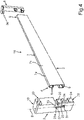
- the rail 2 is shown in perspective. It can also be seen that the profile rail 1 is a three-dimensional molded component.
- the profile rail 2 has a front panel 7 .
- the front panel 7 is designed without interruption.
- a first profile area is integrally formed on this front panel 7 . Viewed in the width direction (x-direction), this profile area directly adjoins the thin front panel 7 to the side.
- This profile area is a hollow chamber 8. This is a first upper hollow chamber viewed in the vertical direction (y-direction).
- the profile rail 2 has a second profile area that differs from the first.
- this profile area is a second, lower hollow chamber 9.
- the hollow chambers 8 and 9 each have delimiting walls which delimit the hollow space in each case.
- a profile rail 2 is a component which has at least one open hollow area delimited by walls.
- the two hollow chambers 8 and 9 are arranged completely behind the front panel 7 . This means that they do not project upwards or downwards beyond the dimensions of the front panel 7 in the height direction. Viewed in the depth direction (z-direction), the hollow chambers 8 and 9 extend without interruption over the entire length of the front panel 7. As in FIG 2 can also be seen, an upper boundary wall 8a of the first, upper hollow chamber 8 is oriented horizontally. It connects directly to an upper edge 7a of the front panel 7.
- the lower hollow chamber 9 has a lower boundary wall 9a. This concludes at the front with a lower boundary edge 7b of the front panel 7 or ends directly thereon.
- the connecting parts 3 and 5 are inserted into the profile rail 2.
- a guided positioning of the connecting parts 3 and 5 on the separate profile rail 2 is provided.
- the hollow chambers 8 and 9 in the exemplary embodiment are formed with a four-sided cross-sectional shape in cross-section viewed perpendicularly to the longitudinal axis A.
- this cross-sectional shape is not completely closed.
- a lower boundary wall 8b is open or is not formed directly adjoining the front panel 7.
- an upper boundary wall 9b of the lower hollow chamber 9 is arranged at a distance from this front panel 7 . This lower hollow chamber 9 is therefore also not completely closed all the way around, viewed in cross section.
- the upper hollow chamber 8 has a smaller width in the width direction (x-direction) than the lower hollow chamber 9.
- the profile rail 2 is designed to be open both at the first end 4 and at the second end 6 .
- the hollow chambers 8 and 9 are designed to be open at these opposite ends 4 and 6 in this regard.
- a first Insertion bracket 10 and a second insertion bracket 11 integrally formed. These insertion mounts 10 and 11 are intended for receiving and inserting and thus also for holding the additional connecting parts 3 and 5 .
- These insertion mounts 10 and 11 are thus formed at the ends by the hollow chambers 8 and 9 which are open at the sides.
- In 3 is the profile rail 2 in a 2 shown from different perspectives.
- a shelf 12 of the shelf assembly 1 is also shown.
- the storage shelf 12 is part of the storage arrangement 1.
- the storage shelf 12 can be a shelf, for example.
- the storage plate 12 has a base plate 13 in the exemplary embodiment. This can be a glass plate, for example.
- the shelf 12 here has an angular, in particular quadrangular configuration. It has a rear edge 14, a front edge 15 and side edges 16 and 17.
- the profile rail 2 is only arranged on the two connecting parts 3 and 5 . In this regard, at locations spaced from the tray 12.
- the storage plate 12 is therefore arranged above the profile rail 2 and at a distance therefrom, viewed in the vertical direction.
- This carrier unit 18 has a modular structure. It has the profile rail 2 and the two separate connecting parts 3 and 5 here.
- the connecting part 3 has a longitudinal axis B. This is oriented here in height direction.
- the connecting part 3 has a receiving rail 19 .
- the receiving rail 19 forms the upper end of the connecting part 3 here.
- the receiving rail 19 has a receiving groove 20 . This is intended to cover the edge area 15a ( 1 ) of the front edge 15 to accommodate. In particular, a front corner area 21 ( 1 ) of the shelf 12 in this receiving groove 20 was added.
- the connecting part 3 has a coupling column 22 .
- the coupling column 22 connects directly to the receiving rail 19 at the bottom.
- the coupling column 22 has coupling elements 23 and 24 here. These are designed to be inserted or plugged into the hollow chambers 8 and 9 in the area of the insertion holder 10 .
- the coupling column 22 has a lead-through structure 25 . This is designed as a continuous lead-through structure 25 .
- This lead-through structure 25 is designed in the manner of a slit.
- This lead-through structure 25 is intended for a food receiving tray 26 ( 7 ) can be passed through the coupling column 22 with a coupling area 27 viewed in the depth direction.
- this food receiving tray 26 which represents an exemplary embodiment of a food receiving container, can be pushed into this feed-through structure 25 from the front, pushed through this feed-through structure 25 and then reaches the profile rail 2 arranged directly behind it directly and immediately therefore pushed onto this profile rail 2 from the front.
- the profile rail 2 In the mounted state of the profile rail 2 on the connecting part 3, the profile rail 2 is therefore directly adjacent to this lead-through structure 25. In this regard, it can even partially protrude into the lead-through structure 25 .
- a suspension area of this type which forms the coupling area 27 in one exemplary embodiment, can thus be attached to the profile rail 2 .
- only such a horizontal, linear assembly scenario is then required in order to then be able to hang or hang up the food receiving tray 26 on the upper edge of the profile rail 2 .
- the connecting part 5 is designed in a corresponding manner. As in 1 and 4 As can be seen, the receiving rail 19 protrudes laterally beyond the coupling column 22 when viewed in the width direction. In this regard, this is a roof-like, cantilevered overhang.
- the rear connecting part 5 is also designed accordingly. In the exemplary embodiment, this is designed with a coupling column, but without such a lead-through structure 25 .
- This roof-like overhang of the receiving rails 19 of the connecting parts 3 and 5 forms a respective overhang piece 19a.
- This overhang piece 19a is intended to be a coupling area for coupling to a Household appliance component of home appliance.
- this can be a wall, for example a vertical side wall 28 ( 9 ) of an inner container 29 of a household refrigeration appliance 30 .
- the household refrigeration appliance 30 is in this context in 9 shown in a schematic perspective view.
- the storage arrangement 1 can thus be easily arranged or fastened laterally on such a side wall 28 .
- an entrance 25a of this lead-through structure 25 is widened.
- boundary edges of this entrance 25a have slopes 31, 32, 33 and 34 inclined outwards. This simplifies the insertion of the coupling area 27 of a food receiving tray 26 .
- FIG. 6 A perspective view of the assembled state of the storage arrangement 1 is shown.
- the front corner area 21 with the edge area 15a and a rear corner area 35 ( 1 ) with an edge area 14a ( 1 ) of the rear edge 14 are received in the respective receiving grooves 20 and 36 of the respective receiving rails 19 of the connecting parts 3 and 5.
- the distance between the profile rail 2 and the shelf 12 shown in the vertical direction can also be seen.
- FIG 7 is the storage arrangement 1 according to FIG 6 shown.
- the already explained food receiving tray 26 is attached to the profile rail 2 from above. Otherwise, the food receiving tray 26 is arranged with a trough area 26a that cantilevers freely. For removal or attachment, it can be provided that the food receiving tray 26 is lifted in the vertical direction, so that a decoupling or a coupling between the coupling area 27 and the profile rail 2 occurs.
- a distance measured in the height direction between the underside of the storage plate 12 and the upper side of the profile rail 2 is greater than an overlapping area between the coupling area 27 and the profile rail 2 in their respective installed state. This allows after decoupling between the Coupling area 27 and the profile rail 2, which in one embodiment takes place in particular only by linear lifting, then linear movement in the width direction and the food receiving tray 26 are completely removed.
- Fig. 1 shows the state in which the food receiving tray 26 is partially pulled forward in the linear horizontal direction, namely, in the depth direction.
- the coupling area 27 is pushed through the lead-through structure 25 so that the coupling area 27 extends in the depth direction on both sides of this depth structure 25 in this illustrated scenario.
- this connecting part 3 also serves as an anti-tilt element.
- the lead-through structure 25 is designed accordingly in this regard. The arrangement of the food receiving tray 26, which is then also freely cantilevered to the front, can therefore be held without any problems.
- the food receiving tray 26 can then also be pulled completely forward and accepted by the carrier unit.
- FIG. 9 a schematic representation of an exemplary embodiment of a domestic refrigeration appliance 30 is shown.
- the storage arrangement 1 is arranged in a receiving space 37 . This can be a refrigerator compartment or a freezer compartment.
- the storage arrangement 1 is arranged on opposite side walls 28 and 40 of the inner container 29 .
- the domestic refrigeration appliance 30 also has a housing 38 and a door 39 .
Landscapes
- Engineering & Computer Science (AREA)
- Chemical & Material Sciences (AREA)
- Combustion & Propulsion (AREA)
- Physics & Mathematics (AREA)
- Mechanical Engineering (AREA)
- Thermal Sciences (AREA)
- General Engineering & Computer Science (AREA)
- Assembled Shelves (AREA)
Applications Claiming Priority (1)
| Application Number | Priority Date | Filing Date | Title |
|---|---|---|---|
| DE102021204418.2A DE102021204418A1 (de) | 2021-05-03 | 2021-05-03 | Ablageanordnung mit einer Profilschiene aus Metall, sowie Haushaltskältegerät |
Publications (1)
| Publication Number | Publication Date |
|---|---|
| EP4086548A1 true EP4086548A1 (fr) | 2022-11-09 |
Family
ID=81325135
Family Applications (1)
| Application Number | Title | Priority Date | Filing Date |
|---|---|---|---|
| EP22168837.7A Withdrawn EP4086548A1 (fr) | 2021-05-03 | 2022-04-19 | Agencement de rangement doté d'un rail profilé métallique, ainsi qu'appareil réfrigérant électroménager |
Country Status (2)
| Country | Link |
|---|---|
| EP (1) | EP4086548A1 (fr) |
| DE (1) | DE102021204418A1 (fr) |
Citations (4)
| Publication number | Priority date | Publication date | Assignee | Title |
|---|---|---|---|---|
| US3261585A (en) * | 1960-04-20 | 1966-07-19 | Victory Metal Mfg Company | Pilaster adapter |
| WO2010099467A2 (fr) * | 2009-02-27 | 2010-09-02 | Electrolux Home Products, Inc. | Etagère évidée et support de tiroir pour réfrigérateur |
| EP2938949A1 (fr) * | 2012-12-31 | 2015-11-04 | BSH Hausgeräte GmbH | Appareil de refroidissement ayant un guide de tiroir |
| EP2414755B1 (fr) * | 2009-03-31 | 2016-09-14 | BSH Hausgeräte GmbH | Appareil frigorifique, en particulier appareil frigorifique domestique, ainsi que élément d'entreposage pour ledit appareil |
-
2021
- 2021-05-03 DE DE102021204418.2A patent/DE102021204418A1/de not_active Withdrawn
-
2022
- 2022-04-19 EP EP22168837.7A patent/EP4086548A1/fr not_active Withdrawn
Patent Citations (4)
| Publication number | Priority date | Publication date | Assignee | Title |
|---|---|---|---|---|
| US3261585A (en) * | 1960-04-20 | 1966-07-19 | Victory Metal Mfg Company | Pilaster adapter |
| WO2010099467A2 (fr) * | 2009-02-27 | 2010-09-02 | Electrolux Home Products, Inc. | Etagère évidée et support de tiroir pour réfrigérateur |
| EP2414755B1 (fr) * | 2009-03-31 | 2016-09-14 | BSH Hausgeräte GmbH | Appareil frigorifique, en particulier appareil frigorifique domestique, ainsi que élément d'entreposage pour ledit appareil |
| EP2938949A1 (fr) * | 2012-12-31 | 2015-11-04 | BSH Hausgeräte GmbH | Appareil de refroidissement ayant un guide de tiroir |
Also Published As
| Publication number | Publication date |
|---|---|
| DE102021204418A1 (de) | 2022-11-03 |
Similar Documents
| Publication | Publication Date | Title |
|---|---|---|
| EP1840473B1 (fr) | Appareil ménager avec un dispositif d'extraction de télescope fixé sur un cadre porteur | |
| WO2009071342A1 (fr) | Appareil réfrigérant | |
| DE102016118267A1 (de) | Haltewinkel, Befestigungssystem und Haushaltsgerät | |
| EP2220446B1 (fr) | Appareil réfrigérant | |
| EP3967958B1 (fr) | Agencement de plaque de rangement pourvu de cadre support doté d'un rail profilé en métal, ainsi qu'un appareil réfrigérateur | |
| EP3805676A1 (fr) | Appareil électroménager pourvu de dispositif de stockage spécifique doté d'un canal de stockage en forme de barre pour une extension de rail | |
| AT411005B (de) | Schubladenführung | |
| EP3519737B1 (fr) | Ensemble destiné à un support pour aliments à cuire comprenant un cadre support et un dispositif d'extension de rail, et appareil électroménager comprenant un tel ensemble | |
| WO2003105631A1 (fr) | Ensemble pour relier un encadrement de tiroir au fond de tiroir | |
| AT522530B1 (de) | Korpusschiene mit Versteifungselement | |
| AT520691B1 (de) | Führungssystem | |
| EP2818813A1 (fr) | Un refrigerateur avec un rail de support pour une etagère | |
| EP4166875A1 (fr) | Dispositif de stockage avec dispositif de suspension doté d'un coupleur d'un plateau de stockage monté coulissant sur un rail pour le support du plateau de stockage, appareil ménager et procédé | |
| DE102021204418A1 (de) | Ablageanordnung mit einer Profilschiene aus Metall, sowie Haushaltskältegerät | |
| EP3783287A1 (fr) | Étagère pourvue d'un support central spécifique pour des parties de plaque séparées | |
| EP3369341B1 (fr) | Élément mural pour un châssis d'un tiroir | |
| DE202007006386U1 (de) | Elektrisches Küchengerät | |
| EP3978847B1 (fr) | Dispositif d'accrochage pour un récipient pour produits alimentaires | |
| DE3135222C2 (fr) | ||
| EP3783288B1 (fr) | Clayette pourvue de cadre de support à trois côtés | |
| WO2022228907A1 (fr) | Appareil frigorifique électroménager doté d'une paroi arrière spécifique d'espace machine, et procédé d'assemblage | |
| EP3559569A1 (fr) | Balconnet de rangement comportant une tablette encliquetée dans un corps de base, ainsi qu'appareil électroménager frigorifique pourvu d'un balconnet de rangement | |
| DE102019217365A1 (de) | Lebensmittel-Aufnahmeschale für ein Haushaltskältegerät mit Koppelschiene zur Kopplung mit unterschiedlichen Führungsvorrichtungen, sowie Anordnung, System und Haushaltskältegerät | |
| DE102010055547A1 (de) | Kabeltragsystem umfassend eine Konsole und eine Gitterrinne | |
| EP1661491B1 (fr) | Cadre de support |
Legal Events
| Date | Code | Title | Description |
|---|---|---|---|
| PUAI | Public reference made under article 153(3) epc to a published international application that has entered the european phase |
Free format text: ORIGINAL CODE: 0009012 |
|
| STAA | Information on the status of an ep patent application or granted ep patent |
Free format text: STATUS: THE APPLICATION HAS BEEN PUBLISHED |
|
| AK | Designated contracting states |
Kind code of ref document: A1 Designated state(s): AL AT BE BG CH CY CZ DE DK EE ES FI FR GB GR HR HU IE IS IT LI LT LU LV MC MK MT NL NO PL PT RO RS SE SI SK SM TR |
|
| STAA | Information on the status of an ep patent application or granted ep patent |
Free format text: STATUS: REQUEST FOR EXAMINATION WAS MADE |
|
| 17P | Request for examination filed |
Effective date: 20230509 |
|
| RBV | Designated contracting states (corrected) |
Designated state(s): AL AT BE BG CH CY CZ DE DK EE ES FI FR GB GR HR HU IE IS IT LI LT LU LV MC MK MT NL NO PL PT RO RS SE SI SK SM TR |
|
| STAA | Information on the status of an ep patent application or granted ep patent |
Free format text: STATUS: EXAMINATION IS IN PROGRESS |
|
| 17Q | First examination report despatched |
Effective date: 20250312 |
|
| STAA | Information on the status of an ep patent application or granted ep patent |
Free format text: STATUS: THE APPLICATION IS DEEMED TO BE WITHDRAWN |
|
| 18D | Application deemed to be withdrawn |
Effective date: 20250715 |