EP4086680B1 - Stumpfgehäuse und organisatoranordnungen - Google Patents
Stumpfgehäuse und organisatoranordnungen Download PDFInfo
- Publication number
- EP4086680B1 EP4086680B1 EP22169002.7A EP22169002A EP4086680B1 EP 4086680 B1 EP4086680 B1 EP 4086680B1 EP 22169002 A EP22169002 A EP 22169002A EP 4086680 B1 EP4086680 B1 EP 4086680B1
- Authority
- EP
- European Patent Office
- Prior art keywords
- organizer
- assembly
- trays
- basket
- extending
- Prior art date
- Legal status (The legal status is an assumption and is not a legal conclusion. Google has not performed a legal analysis and makes no representation as to the accuracy of the status listed.)
- Active
Links
Images





Classifications
-
- G—PHYSICS
- G02—OPTICS
- G02B—OPTICAL ELEMENTS, SYSTEMS OR APPARATUS
- G02B6/00—Light guides; Structural details of arrangements comprising light guides and other optical elements, e.g. couplings
- G02B6/44—Mechanical structures for providing tensile strength and external protection for fibres, e.g. optical transmission cables
- G02B6/4439—Auxiliary devices
- G02B6/444—Systems or boxes with surplus lengths
- G02B6/4453—Cassettes
- G02B6/4455—Cassettes characterised by the way of extraction or insertion of the cassette in the distribution frame, e.g. pivoting, sliding, rotating or gliding
-
- G—PHYSICS
- G02—OPTICS
- G02B—OPTICAL ELEMENTS, SYSTEMS OR APPARATUS
- G02B6/00—Light guides; Structural details of arrangements comprising light guides and other optical elements, e.g. couplings
- G02B6/44—Mechanical structures for providing tensile strength and external protection for fibres, e.g. optical transmission cables
- G02B6/4439—Auxiliary devices
- G02B6/444—Systems or boxes with surplus lengths
- G02B6/4441—Boxes
- G02B6/4442—Cap coupling boxes
-
- G—PHYSICS
- G02—OPTICS
- G02B—OPTICAL ELEMENTS, SYSTEMS OR APPARATUS
- G02B6/00—Light guides; Structural details of arrangements comprising light guides and other optical elements, e.g. couplings
- G02B6/44—Mechanical structures for providing tensile strength and external protection for fibres, e.g. optical transmission cables
- G02B6/4439—Auxiliary devices
- G02B6/444—Systems or boxes with surplus lengths
- G02B6/4453—Cassettes
- G02B6/4454—Cassettes with splices
-
- G—PHYSICS
- G02—OPTICS
- G02B—OPTICAL ELEMENTS, SYSTEMS OR APPARATUS
- G02B6/00—Light guides; Structural details of arrangements comprising light guides and other optical elements, e.g. couplings
- G02B6/44—Mechanical structures for providing tensile strength and external protection for fibres, e.g. optical transmission cables
- G02B6/4439—Auxiliary devices
- G02B6/444—Systems or boxes with surplus lengths
- G02B6/4452—Distribution frames
- G02B6/44526—Panels or rackmounts covering a whole width of the frame or rack
-
- G—PHYSICS
- G02—OPTICS
- G02B—OPTICAL ELEMENTS, SYSTEMS OR APPARATUS
- G02B6/00—Light guides; Structural details of arrangements comprising light guides and other optical elements, e.g. couplings
- G02B6/44—Mechanical structures for providing tensile strength and external protection for fibres, e.g. optical transmission cables
- G02B6/4439—Auxiliary devices
- G02B6/4471—Terminating devices ; Cable clamps
Definitions
- the present disclosure relates generally to closures, such as for fiber optic cable connections, and more specifically to improved organizer assemblies for butt closures.
- closures also referred to as “butt” or “domed” closures
- the cables enter the closure through a sealed base, and connection of the cable elements occurs within the closure.
- fiber optic cables spliced-together optical fibers are held within the closure.
- EP 0 490 644 A1 describes an optical fiber cable closure with trays pivotably mounted to a frame. Each tray is adapted to hold a plurality of spliced optical fiber portions by extending ribs in channels of at least one organizing module.
- organizer assemblies for use with butt closures would be advantageous.
- organizer assemblies which address one of more of the above-stated deficiencies would be advantageous.
- the claimed invention provides an organizer assembly according to claim 1. Embodiments are defined by the dependent claims.
- Closures 10 in accordance with the present disclosure may advantageously provide improved routing features which reduce kinking and attenuation risks. Additionally or alternatively, closures 10 and organizer baskets thereof in accordance with the present disclosure may advantageously provide improved features for securing and positioning organizer trays thereof in a variety of positions, thus advantageously allowing efficient and effective fiber-populating, splicing, etc.
- closures 10 and organizer baskets thereof in accordance with the present disclosure, and according to the claimed invention, the splice modules which may be utilized with such closures 10 and/or organizer baskets, advantageously provide improved flexibility with respect to the types of splices and/or other components that can be held therein.
- a closure 10 in accordance with the present disclosure includes a cover 20.
- Cover 20 is generally a domed cover which defines an interior 22 and an opening 24 which provides access to the interior 22.
- Cover 20 may include an inner surface 26 which defines the interior 22 and an opposing outer surface 28 which is exposed to the external environment.
- An organizer assembly 30 may be insertable into (and thus disposed within) the interior 22, such as along a longitudinal axis of the closure 10.
- Organizer assembly 30 includes one or more organizer trays 200 and may include other suitable components for facilitating transmission component connections. For example, in the case of use with fiber optic cables, splices between optical fibers thereof may be housed in the various splice trays.
- a base 40 may be insertable at least partially into (and thus disposed at least partially within) the interior 22.
- organizer assembly 30 may be connected to the base 40, such that insertion of the base 40 causes insertion of the tray assembly 30 into the interior 22.
- Cables 42 may be inserted through the base 40 into the interior 22, and connection between transmission elements thereof (such as optical fibers) may be made within the interior 22, such as in the organizer trays 200 of the organizer assembly 30.
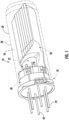
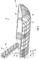
- FIGS. 2 through 14 illustrate various embodiments of organizer assemblies 30 and components thereof in accordance with embodiments of the present disclosure.
- a mutually orthogonal coordinate system is defined for organizer assemblies 30 in accordance with the present disclosure, and may include a mutually orthogonal longitudinal axis 102, lateral axis 104, and transverse axis 106.
- organizer assemblies 30 in accordance with the present disclosure includes a primary basket 110.
- the primary basket 110 generally forms at least a portion of the base exterior of the organizer assembly 30, and includes an exterior surface 112 and an interior surface 114.
- the primary basket 110 extends along the longitudinal axis 102 between a first end 116 and a second end 118.
- the first end 116 is an open end, as shown, such that cables 42 or transmission elements thereof being directed along and parallel to the longitudinal axis 102 can enter or exit an interior 120 of the primary basket 110 through the first end 116.
- the second end 118 is a closed end, as shown, such that cables 42 or transmission elements thereof being directed along and parallel to the longitudinal axis 102 cannot enter an interior 120 of the primary basket 110 through the second end 118, and instead encounter a surface of the primary basket 110.
- the primary basket 110 may further extend along the lateral axis 104 between a first side 122 and a second side 124, both of which may be closed (as discussed above with respect to second end 118).
- a length between the first end 116 and second end 118 is greater than a length between the first side 122 and the second side 124.
- transitions between the closed second end 118 portion and a base portion 126, the closed first side portion 122 and the base portion 126, the closed second side portion 124 and the base portion 126, the closed second end 118 portion and closed first side portion 122, and/or the closed second end 118 portion and closed second side portion 124 are curved.
- Basket 110 may generally be utilized to house excess cables 42 and/or transmission elements thereof as the cables 42 and/or transmission elements thereof are routed through the closure 10 and organizer assembly 30 thereof.
- Primary basket 110 may further include an upper peripheral lip 128, which may extend between the first end 116 and second end 118, such as on the sides 122, 124, and may further extend between the sides 122, 124, such as along the closed second end 118.
- the lip 128 may extend along an upper edge (along the traverse axis 106) of the primary basket 110, such as along the sides 122, 124 and second end 118.
- a cover plate 130 may be provided.
- Cover plate 130 may be removably positioned on the basket 110, such as on the lip 128 thereof. Hook-and-loop fasteners or other suitable fastening apparatus may be utilized to removably fasten the cover plate 130 to the basket 110.
- Cover plate 130 may protect and help to secure portions of cables 42 and transmission elements thereof which are disposed in and routed through the interior 120 of basket 110.
- basket 110 may further include a plurality of retainer tabs 132, each of which extends from the basket 110 into the interior 120.
- the tabs 132 may be connected to the basket 110 at the upper edge of the basket 110, such as adjacent the lip 128. Further, in exemplary embodiments, the tabs 132 are removable. In some embodiments, for example, the tabs 132 may be removed when a secondary basket (as discussed herein) is connected. Tabs 132 may generally assist in routing and retaining cables 42 and transmission elements in the interior 120 during assembly, splicing, etc., thereof.
- a connector shaft 138 may extend from the first end 116 along the longitudinal axis 102, such that at least a portion of the connector shaft 138 is exterior to the primary basket 110.
- the connector shaft 138 may connect to the base 40, thus connecting the organizer assembly 30 and base 40 together.
- Bracket assembly 140 extends along the transverse axis 106 from the primary basket 110, such as at the first end 116.
- Bracket assembly 140 includes a main body 142 and a plurality of hinge assemblies 144.
- the hinge assemblies 144 may be spaced apart in a linear array along the transverse axis 106.
- the hinge assemblies 144 are stepped along the transverse axis 106.
- the linear array of the hinge assemblies 144 is angled relative to the transverse axis 106, rather than being directed along or parallel to the transverse axis 106.
- At least the portion of the main body 142 which includes the hinge assemblies 144 may also be so angled. Such angle may be between the transverse axis 106 and the longitudinal axis 102, as shown.
- organizer assemblies 30 in accordance with the present disclosure may include a second basket 150 which may be rotatably and removably connectable to the bracket assembly 140.
- FIGS. 2 and 3 illustrate the secondary basket 150 rotatably connected to the bracket assembly 140.
- the secondary basket 150 may be connected to the bracket assembly 140 below the plurality of hinge assemblies 144 along the transverse axis 106, such as between the plurality of hinge assemblies 144 (such as the lower-most hinge assembly 144) and the interior surface 114 of the primary basket 110 along the transverse axis 106.
- the secondary basket 150 may be rotatable between a first position wherein the secondary basket 150 is aligned along the longitudinal axis 102 and a second position wherein the secondary basket 150 is aligned along the transverse axis 106 or at an angle between the longitudinal axis 102 and transverse axis 106 (as shown in FIGS. 2 and 3 ).
- the secondary basket 150 may be removable, such that it can be utilized as needed for cable 42 (and transmission elements thereof) routing and set aside/discarded when not needed.
- the secondary basket 150 includes an exterior surface 152 and an interior surface 154.
- the secondary basket 150 may extend (such as along the longitudinal axis 102 when in the first position) between a first end 156 and a second end 158.
- the first end 156 may be an open end, as shown, such that cables 42 or transmission elements thereof being directed along and parallel to the longitudinal axis 102 can enter or exit an interior 160 of the secondary basket 150 through the first end 156, when the secondary basket 150 is in the first position.
- the second end 158 may be a closed end, as shown, such that cables 42 or transmission elements thereof being directed along and parallel to the longitudinal axis 102 cannot enter an interior 160 of the secondary basket 150 through the second end 158, and instead encounter a surface of the primary basket 110, when the secondary basket 150 is in the first position.
- the secondary basket 150 may further extend along the lateral axis 104 between a first side 162 and a second side 164, both of which may be closed (as discussed above with respect to second end 118).
- a length between the first end 156 and second end 158 is greater than a length between the first side 162 and the second side 164.
- transitions between the closed second end 158 portion and a base portion 166, the closed first side portion 162 and the base portion 166, the closed second side portion 164 and the base portion 166, the closed second end 158 portion and closed first side portion 162, and/or the closed second end 158 portion and closed second side portion 164 are curved.
- the area of the interior 160 may be less than the area of the interior 120, the length between the first end 156 and second end 158 may be less than the length between the first end 116 and second end 118, and/or the length between the first side 162 and second side 164 is less than the length between the first side 122 and second side 124, such that the secondary basket 150 can fit at least partially within the primary basket 110 (such as the interior 120 thereof).
- Secondary basket 150 may further include an upper peripheral lip 168, which may extend between the first end 156 and second end 158, such as on the sides 162, 164, and may further extend between the sides 162, 164, such as along the closed second end 158.
- the lip 168 may extend along an upper edge (along the traverse axis 106) of the secondary basket 150, such as along the sides 162, 164 and second end 158.
- basket 150 may further include a plurality of retainer tabs 172, each of which extends from the basket 150 into the interior 160.
- the tabs 172 may be connected to the basket 150 at the upper edge of the basket 150, such as adjacent the lip 168. Tabs 172 may generally assist in routing and retaining cables 42 and transmission elements in the interior 160 during assembly, splicing, etc., thereof.
- One or more connector arms 174 may extend from the first end 156 (such as along the longitudinal axis 102 when the secondary basket 150 is in the first position).
- the connector arms 174 may be removably connected to the bracket assembly 140, thus rotatably connecting the secondary basket 150 thereto.
- protrusions 176 provided on the arms 174 may be inserted in depressions 178 defined in the main body 142 to rotatably connect the secondary basket 150 thereto.
- each hinge assembly 144 may include at least one positioning tab 180 and at least one release tab 182.
- each hinge assembly 144 may include two positioning tabs 180 and a release tab 182, with the release tab 182 disposed between the positioning tabs 180 along the lateral axis 104.
- Each positioning tab 180 may be a generally tapered protrusion extending along the transverse axis 106 from the main body 142.
- Each release tab 182 may extend along the longitudinal axis 102 from the main body 142, and may thus protrude from the main body 142 farther than the positioning tab(s) 180 along the longitudinal axis 102.
- Each bracket assembly 144 may further include one or more depressions 184 (which may for example be through-holes) defined in the main body 142.
- organizer assemblies 30 in accordance with the present disclosure further include a plurality of organizer trays 200.
- Each organizer tray 200 is rotatably connectable, and thus may be rotatably connected, to the bracket assembly 140, at one of the plurality of hinge assemblies 144.
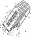
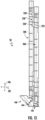
- Each organizer tray 200 is rotatable between a first position wherein the organizer tray 200 is aligned along the longitudinal axis 102 (as shown in FIGS. 5 , 6 , and 12 ) and a second position wherein the organizer tray 200 is aligned along the transverse axis 106 (as shown in FIGS. 7 , 8 , and 13 ).
- each organizer tray 200 may include a main body 202.
- Main body 202 may, for example, include a base wall 204, a first sidewall 206, a second sidewall 208, and a front wall 210, and may further define a rear end 212.
- First sidewall 206 and second sidewall 208 may be spaced apart along the lateral axis 104.
- Front wall 210 and rear end 212 may be spaced apart (such as along the longitudinal axis 102 when in the first position).
- the rear end 212 may be an open end, as shown, such that cables 42 or transmission elements thereof being directed along and parallel to the longitudinal axis 102 can enter or exit an interior 214 of the organizer tray 200 through the rear end 212, when the organizer tray 200 is in the first position.
- the front wall 210 and sidewalls 206, 208 may define a closed end and closed sides.
- a plurality of apertures 216 may be defined in the base wall 204, such as at the rear end 212. Each aperture 216 may be utilized to secure a cable 42 (or transmission element thereof) directly to the base wall 204 and organizer tray 200 thereof, such as using a suitable zip-tie or other suitable fastener. Notably, no additional cable/transmission element securement components are included on the organizer tray 200.
- Organizer tray 200 may further include one or more connector arms 220 which may extend from the main body 202.
- each connector arm 220 may extend from the base wall 204, such as along the transverse axis 106 when in the first position.
- the connector arms 220 may be removably connected to the hinge assembly 144, thus rotatably connecting the organizer tray 200 thereto.
- protrusions 222 provided on the arms 220 may be inserted in depressions 184 to rotatably connect the organizer tray 200 to the hinge assembly 144.
- each of the plurality of organizer trays 200 is rotatable between a first position and a second position. Further, each organizer tray 200 may advantageously be releasably securable in the second position, thus facilitating efficient loading of cables 42 and transmission elements thereof, splicing, etc., into other organizer trays 200 and the assembly 30 generally.
- the hinge assembly 144 which rotatable connects the organizer tray 200 to the bracket assembly 140 may releasably secure the organizer tray 200 in the second position.
- the one or more positioning tabs 182 of the associated hinge assembly 144 may contact and releasably secure the organizer tray 200 in the second position.
- the organizer tray 200 may include one or more contact tabs 224, each of which extends from the rear end 212 of the body 202.
- each contact tab 224 may contact a positioning tab 182 and releasably secure the organizer tray 200 in the second position.
- each contact tab 224 may ride up the tapered front surface of a positioning tab 182 and then rest in contact with a rear surface of the positioning tab 182 when the organizer tray 200 reaches the second position.
- the organizer tray 200 may be released from being secured in the second position to move from the second position to the first position.
- movement of the release tab 182 may cause movement of the positioning tab(s) 180 out of contact with the organizer tray 200 (such as the contact tab(s) 224) thereof such that the organizer tray 200 can move from the second position to the first position.
- a user may apply force to the release tab 182 to cause such movement.
- such force may pivot the release tab 182 and, due to a material connection between the release tab 182 and positioning tab(s) 180, also cause pivoting of the positioning tab(s) 180.
- each organizer tray 200 may advantageously include features for ensuring and securing proper positioning of the organizer trays 200 relative to each other in the first and second positions.
- each organizer tray 200 may include one or more pluralities of positioning slots 230 and one or more positioning tabs 232.
- the slots 230 may, for example, be defined in exterior surfaces of the first sidewall 206 and/or second sidewall 208, such as adjacent or at the base wall 204.
- the positioning tab(s) 232 may extend from the first sidewall 206 and/or second sidewall 208, such as at a top of the organizer tray 200 opposite the base wall 204.
- a positioning tab 232 of an organizer tray 200' may be inserted into a different positioning slot 230 of a plurality of positioning slots 230 in a neighboring organizer tray 200" depending on the positions of the organizer trays 200.
- a positioning tab 232 of an organizer tray 200' may be inserted in one of the plurality of positioning slots 230' of a neighboring organizer tray 200" when these trays 200', 200" (such as, for example, the plurality of organizer trays 200) is in the first position (see FIG. 12 ).
- the positioning tab 232 of the organizer tray 200' may be inserted in another one of the plurality of positioning slots 230" of the neighboring organizer tray 200" when these trays 200', 200" (such as, for example, the plurality of organizer trays 200) is in the second position (see FIG. 13 ).
- the organizer trays 200 may be removable from the bracket assembly 140 and organizer assembly 30 generally.
- the positioning tab 232 of the organizer tray 200' may further be inserted in yet another one of the plurality of positioning slots 230′′′ of the neighboring organizer tray 200" when these trays 200', 200" (such as, for example, the plurality of organizer trays 200) are removed from the bracket assembly 140 and stacked together, such as in a vertical array (see FIG. 14 ). Accordingly, organization and retention of the organizer trays 200 is advantageously facilitated even when the organizer trays 200 are not connected to the bracket assembly 140 and organizer assembly 30 generally.
- each organizer tray 200 accommodates a plurality of splice modules 250.
- Each splice module 250 is removably connected to the organizer tray 200, such as to the base wall 204 thereof.
- base wall 204 may include a plurality of module mounting locations 240.
- each of the module mounting locations 240 may include a plurality of leg slots 242 which may be defined through the base wall 204 and one or more pluralities of positioning slots 244 which may be defined through the base wall 204.
- the leg slots 242 may, for example, define at least a portion of a periphery of the module mounting location 240, and may for example, be disposed at corners of the module mounting location 240.
- Each plurality of positioning slots 244 may be defined within the periphery of the module mounting location 240, and may for example extend in a linear array.
- the leg slots 242 and positioning slots 244 may generally facilitate removable connection of a splice module 250 to the organizer tray at a module mounting location 240.
- Each splice module 250 includes a base 252 and may include a plurality of legs 254 extending from the base 252, such as below the base 252 as shown.
- the legs 254 may further extend from and at least partially define a periphery of the base 252, and may further be disposed at corners of the base 252.
- each leg 254 may be inserted into one of the leg slots 242 of a module mounting location 240.
- a splice module 250 may include one or more cantilevered arms 256 extending from the base 252, such as below the base 252 as shown.
- Each cantilevered arm 256 may include a tab 258 at a distal end thereof.
- the cantilevered arm 256 such as the tab 258 thereof, may be inserted in one of a plurality of positioning slots 244 of a module mounting location 240.
- a splice module 250 may be removably connectable to an organizer tray 200, such as at a module mounting location 240, in multiple different orientations.
- the plurality of positioning slots 244 may be oriented such that the cantilevered arm 256, such as the tab 258 thereof, may be inserted in a different one of a plurality of positioning slots 244 depending on the orientation of the splice module 250.
- Splice modules 250 in accordance with the present disclosure may advantageously be dual material components.
- splice modules 250 may further include one or more overmolded portions 260 which are disposed on portions of the base 252, such as on a lower surface and sidewalls thereof.
- the overmolded portions 260 advantageously provide improved structural integrity, rigidity, and protection.
- the base 252, as well as the legs 254 and cantilevered arms 256 thereof, may for example, be formed from a hard plastic such as polycarbonate or nylon.
- the overmolded portions 260 may be formed from suitable elastomers, such as vulcanized elastomers.
- Splice modules 250 in accordance with the present disclosure further include a plurality of partitions 262, each of which may extend from the base 252.
- the partitions 262 may be generally parallel to each other, and neighboring partitions 262 define channels 264 therebetween.
- Each channel 264 defines and extends along a longitudinal channel axis 265, as shown.
- one or more arms 266 extends from the neighboring partitions 262 into the channels 264 defined by such neighboring partitions 262. Such arms 266 extend into the channels 264 at an oblique angle to the longitudinal channel axis 265, as shown.
- a first partition 262' of neighboring partitions 262 includes one or more arms 266 extending into a channel 264 defined by the neighboring partitions 262, and a second partition 262" of neighboring partitions 262 includes one or more arms 266 extending into the channel 264 defined by the neighboring partitions 262. Further, according to the claimed invention, the one or more arms 266 extending into a channel 264 from a first partition 262' extends in a direction opposite the direction of the one or more arms 266 extending into the channel 264 from a second partition 262".
- partitions 262 and arms 266 of splice modules 250 may be formed from suitable elastomers, such as vulcanized elastomers.
- Splice modules 250 in accordance with the present disclosure, and in particular the configuration of the partitions 262 and arms 266, are particularly advantageous due to their versatility and flexibility in accommodating various components.
- a channel 264 of a splice module 250 may be capable of holding triple-stacked single spliced transmission elements, double-stacked ribbon spliced transmission elements, mechanical splices, splitter modules from 1:2 to 1:32, PLCs, etc.
- Organizer trays 200 may further include one or more retainer tabs 270, each of which may extend from a wall, such wall 206, 208, or 210, into the interior 214.
- Such retainer tabs 270 may generally assist in routing and retaining cables 42 and transmission elements in the interior 214 during assembly, splicing, etc., thereof.
Landscapes
- Physics & Mathematics (AREA)
- General Physics & Mathematics (AREA)
- Optics & Photonics (AREA)
- Light Guides In General And Applications Therefor (AREA)
- Packaging Of Annular Or Rod-Shaped Articles, Wearing Apparel, Cassettes, Or The Like (AREA)
- Rigid Containers With Two Or More Constituent Elements (AREA)
- Mechanical Coupling Of Light Guides (AREA)
- Hinges (AREA)
- Knitting Machines (AREA)
Claims (8)
- Organisatoranordnung (30) für einen Stoßverschluss (10), wobei die Organisatoranordnung (30) ein zueinander orthogonales Koordinatensystem definiert, das eine Längsachse (102), eine laterale Achse (104) und eine Querachse (106) umfasst, wobei die Organisatoranordnung (30) Folgendes umfasst:einen Primärkorb (110), der sich entlang der Längsachse (102) zwischen einem ersten offenen Ende (116) und einem zweiten geschlossenen Ende (118) erstreckt, wobei der Primärkorb (110) einen Innenraum (120) definiert;eine Halterungsanordnung (140), die sich entlang der Querachse (106) am ersten offenen Ende (116) des Primärkorbs (110) erstreckt, wobei die Halterungsanordnung (140) eine Vielzahl von Scharnieranordnungen (144) umfasst;eine Vielzahl von Organisatorschalen (200), wobei jede der Vielzahl von Organisatorschalen (200) drehbar mit der Halterungsanordnung (140) an einer der Vielzahl von Scharnieranordnungen (144) verbindbar ist, wobei jede der Vielzahl von Organisatorschalen (200) zwischen einer ersten Position, in der die Organisatorschale entlang der Längsachse (102) ausgerichtet ist, und einer zweiten Position, in der die Organisatorschale entlang der Querachse (106) ausgerichtet ist, drehbar ist; undeine Vielzahl von Spleißmodulen (250), die entfernbar mit jeder der Vielzahl von Organisatorschalen (200) verbunden ist, wobei jedes der Vielzahl von Spleißmodulen (250) eine Basis (252) und eine Vielzahl von Trennwänden (262) umfasst, die sich von der Basis (252) erstrecken, wobei benachbarte Trennwände der Vielzahl von Trennwänden Kanäle (264) dazwischen definieren, wobei jeder Kanal (264) eine Kanallängsachse (265) definiert und sich entlang der Kanallängsachse (265) zwischen einem ersten Ende und einem zweiten Ende erstreckt, und weiter einen oder mehrere Arme (266) umfasst, die sich von jeder benachbarten Trennwand (262) in jeden Kanal (264), der durch die benachbarte Trennwand definiert ist, in einem schrägen Winkel zur Kanallängsachse (265) erstrecken, dadurch gekennzeichnet, dass sich der eine oder die mehreren Arme (266), die sich in einen Kanal (264) von einer ersten Trennwand (262') der benachbarten Trennwände erstrecken, in einer ersten Richtung zu dem ersten Ende des Kanals (264) erstrecken und sich der eine oder die mehreren Arme (266), die sich in den Kanal von einer zweiten Trennwand (262") der benachbarten Trennwände erstrecken, in einer zweiten Richtung, die der ersten Richtung entgegengesetzt ist, zu dem zweiten Ende des Kanals (264) erstrecken.
- Organisatoranordnung (30) nach Anspruch 1, wobei der Primärkorb (110) weiter eine obere Umfangslippe (128) umfasst, die sich zwischen dem ersten Ende (116) und dem zweiten Ende (118) erstreckt, und wobei der Primärkorb (110) weiter eine Vielzahl von entfernbaren Haltelaschen (132) umfasst, wobei jede der entfernbaren Haltelaschen (132) mit dem Primärkorb (110) benachbart zu der oberen Umfangslippe (128) verbindbar ist.
- Organisatoranordnung (30) nach Anspruch 1, weiter umfassend einen Sekundärkorb (150), der drehbar mit der Halterungsanordnung (140) unterhalb der Vielzahl von Scharnieranordnungen (144) entlang der Querachse (106) verbindbar ist.
- Organisatoranordnung (30) nach Anspruch 1, wobei die Vielzahl von Scharnieranordnungen (144) entlang der Querachse (106) abgestuft ist.
- Organisatoranordnung (30) nach Anspruch 1, wobei jede der Vielzahl von Scharnieranordnungen (144) eine Positionierungslasche (180) und eine Freigabelasche (182) umfasst, wobei jede der Vielzahl von Organisatorschalen (200) in Kontakt mit der Positionierungslasche (180) einer der Vielzahl von Scharnieranordnungen (144) steht und lösbar in der zweiten Position durch diese befestigt ist.
- Organisatoranordnung (30) nach Anspruch 1, wobei jede der Vielzahl von Organisatorschalen (200) einen Körper (202) umfasst, der eine Basiswand (204) einschließt, wobei jede Basiswand (204) eine Vielzahl von Modulmontagestellen (240) umfasst, wobei jede Modulmontagestelle (240) eine Vielzahl von durch die Basiswand (204) definierten Beinschlitzen (242) und eine Vielzahl von durch die Basiswand (204) definierten Positionierungsschlitzen (244) umfasst.
- Organisatoranordnung (30) nach Anspruch 6, wobei jedes der Vielzahl von Spleißmodulen (250) weiter eine Vielzahl von Beinen (254) umfasst, die sich unter der Basis (252) erstrecken, und einen freitragenden Arm (256), der sich unterhalb der Basis (252) erstreckt, wobei der freitragende Arm (256) eine Lasche (258) umfasst, und wobei jedes Bein (254) konfiguriert ist, in einen Beinschlitz (242) eingeführt zu werden, und die Lasche (258) konfiguriert ist, in einen Positionierungsschlitz (244) eingeführt zu werden, um eines der Vielzahl von Spleißmodulen (250) entfernbar mit einer der Vielzahl von Organisatorschalen (200) zu verbinden.
- Organisatoranordnung (30) nach Anspruch 1, wobei jedes der Vielzahl von Spleißmodulen (250) einen oder mehrere umspritzte Abschnitte (260) umfasst.
Priority Applications (1)
| Application Number | Priority Date | Filing Date | Title |
|---|---|---|---|
| EP24220533.4A EP4509895A3 (de) | 2018-05-14 | 2019-05-14 | Stumpfverschlüsse und organisatoranordnungen dafür |
Applications Claiming Priority (4)
| Application Number | Priority Date | Filing Date | Title |
|---|---|---|---|
| US201862671132P | 2018-05-14 | 2018-05-14 | |
| US201962812632P | 2019-03-01 | 2019-03-01 | |
| PCT/US2019/032120 WO2019222148A2 (en) | 2018-05-14 | 2019-05-14 | Butt closures and organizer assemblies therefor |
| EP19726857.6A EP3794391B1 (de) | 2018-05-14 | 2019-05-14 | Stumpfverschlüsse und organisatoranordnungen dafür |
Related Parent Applications (2)
| Application Number | Title | Priority Date | Filing Date |
|---|---|---|---|
| EP19726857.6A Division-Into EP3794391B1 (de) | 2018-05-14 | 2019-05-14 | Stumpfverschlüsse und organisatoranordnungen dafür |
| EP19726857.6A Division EP3794391B1 (de) | 2018-05-14 | 2019-05-14 | Stumpfverschlüsse und organisatoranordnungen dafür |
Related Child Applications (1)
| Application Number | Title | Priority Date | Filing Date |
|---|---|---|---|
| EP24220533.4A Division EP4509895A3 (de) | 2018-05-14 | 2019-05-14 | Stumpfverschlüsse und organisatoranordnungen dafür |
Publications (2)
| Publication Number | Publication Date |
|---|---|
| EP4086680A1 EP4086680A1 (de) | 2022-11-09 |
| EP4086680B1 true EP4086680B1 (de) | 2025-01-01 |
Family
ID=66655491
Family Applications (3)
| Application Number | Title | Priority Date | Filing Date |
|---|---|---|---|
| EP24220533.4A Pending EP4509895A3 (de) | 2018-05-14 | 2019-05-14 | Stumpfverschlüsse und organisatoranordnungen dafür |
| EP22169002.7A Active EP4086680B1 (de) | 2018-05-14 | 2019-05-14 | Stumpfgehäuse und organisatoranordnungen |
| EP19726857.6A Active EP3794391B1 (de) | 2018-05-14 | 2019-05-14 | Stumpfverschlüsse und organisatoranordnungen dafür |
Family Applications Before (1)
| Application Number | Title | Priority Date | Filing Date |
|---|---|---|---|
| EP24220533.4A Pending EP4509895A3 (de) | 2018-05-14 | 2019-05-14 | Stumpfverschlüsse und organisatoranordnungen dafür |
Family Applications After (1)
| Application Number | Title | Priority Date | Filing Date |
|---|---|---|---|
| EP19726857.6A Active EP3794391B1 (de) | 2018-05-14 | 2019-05-14 | Stumpfverschlüsse und organisatoranordnungen dafür |
Country Status (6)
| Country | Link |
|---|---|
| US (3) | US11487071B2 (de) |
| EP (3) | EP4509895A3 (de) |
| CA (1) | CA3100340A1 (de) |
| ES (1) | ES2928209T3 (de) |
| MX (2) | MX2020012100A (de) |
| WO (1) | WO2019222148A2 (de) |
Families Citing this family (10)
| Publication number | Priority date | Publication date | Assignee | Title |
|---|---|---|---|---|
| EP4509895A3 (de) | 2018-05-14 | 2025-06-18 | AFL Telecommunications LLC | Stumpfverschlüsse und organisatoranordnungen dafür |
| EP4042219B1 (de) * | 2019-10-08 | 2023-12-06 | AFL Telecommunications LLC | Organisatorbaugruppen für faseroptische verschlüsse |
| MX2023008697A (es) * | 2021-01-27 | 2023-08-01 | Afl Telecommunications Llc | Alojamiento y clip para fibra optica. |
| WO2022192788A1 (en) * | 2021-03-12 | 2022-09-15 | Commscope Technologies Llc | Enclosure and fiber optic organizer including rotating trays |
| US12044897B2 (en) * | 2021-06-11 | 2024-07-23 | Afl Telecommunications Llc | Fiber optic closure and adapter for receptacle |
| JP2024527107A (ja) * | 2021-07-29 | 2024-07-19 | エーエフエル・テレコミュニケーションズ・エルエルシー | 光ファイバ用クロージャ及びオーガナイザアセンブリ |
| JP2024543084A (ja) * | 2021-11-19 | 2024-11-19 | エーエフエル・テレコミュニケーションズ・エルエルシー | バットクロージャ及びそのオーガナイザアセンブリ |
| US20250028132A1 (en) * | 2021-11-19 | 2025-01-23 | Afl Telecommunications Llc | Closure and organizer assembiles therefor |
| US12613391B2 (en) | 2023-05-23 | 2026-04-28 | Afl Telecommunications Llc | Bracket assembly for fiber optic closures and organizer assemblies |
| WO2026015387A1 (en) * | 2024-07-12 | 2026-01-15 | Afl Telecommunications Llc | Butt closures and organizer assemblies therefor |
Family Cites Families (59)
| Publication number | Priority date | Publication date | Assignee | Title |
|---|---|---|---|---|
| US4927227A (en) | 1988-10-31 | 1990-05-22 | At&T Bell Laboratories | Optical fiber cable closure |
| GB8826062D0 (en) | 1988-11-07 | 1988-12-14 | Raychem Sa Nv | Splice case for optical fibre cable |
| US5185845A (en) | 1990-12-13 | 1993-02-09 | At&T Bell Laboratories | Optical fiber closure having enhanced storage capability |
| FR2687744B1 (fr) * | 1992-02-21 | 1994-04-08 | Mars Actel | Ensemble de modules plats articules. |
| US5323480A (en) | 1992-11-25 | 1994-06-21 | Raychem Corporation | Fiber optic splice closure |
| US5479553A (en) | 1993-04-19 | 1995-12-26 | Raychem Corporation | Fiber optic splice closure |
| TW286371B (de) * | 1995-03-31 | 1996-09-21 | Minnesota Mining & Mfg | |
| US5566269A (en) * | 1995-05-30 | 1996-10-15 | The Whitaker Corporation | Strain relieving holder for optical fiber cable |
| US5530786A (en) * | 1995-05-30 | 1996-06-25 | The Whitaker Corporation | Holding for optical fiber splice couplings |
| US6009224A (en) * | 1997-11-06 | 1999-12-28 | Allen; Barry Wayne | Fiber optic organizer with lockable trays and method of accessing a tray |
| WO1999042882A1 (en) | 1998-02-20 | 1999-08-26 | Alcoa Fujikura Ltd. | Fiber optic splice enclosure |
| US6507691B1 (en) | 1999-03-22 | 2003-01-14 | Tyco Electronics Corporation | Fiber optic splice organizer with splicing tray and associated method |
| US6418266B1 (en) * | 1999-08-16 | 2002-07-09 | Preformed Line Products Company | Flip tray system for use in an optical fiber splice case |
| US6453107B1 (en) * | 1999-08-31 | 2002-09-17 | Lucent Technologies Inc. | Tray locking feature for a fiber enclosure |
| JP4162833B2 (ja) * | 2000-05-17 | 2008-10-08 | 株式会社ジャパンリーコム | 心線接続余長収納ケース |
| US6434313B1 (en) | 2000-10-31 | 2002-08-13 | Corning Cable Systems Llc | Fiber optic closure with couplers and splice tray |
| US7272291B2 (en) | 2005-08-25 | 2007-09-18 | Adc Telecommunications, Inc. | Splice chip device |
| US7333706B2 (en) | 2005-08-31 | 2008-02-19 | 3M Innovative Properties Company | Enclosure and organizer for telecommunication lines and splices |
| US7418183B2 (en) | 2006-02-08 | 2008-08-26 | Charles Industries, Ltd. | Fiber optic splice enclosure |
| US20070280619A1 (en) * | 2006-05-23 | 2007-12-06 | Conner Mark E | Multi-directional optical splice organizer |
| US7418182B2 (en) * | 2006-10-10 | 2008-08-26 | Adc Telecommunications, Inc. | Cable management drawer with access panel |
| US7936960B2 (en) | 2006-11-09 | 2011-05-03 | Corning Cable Systems Llc | Optical fiber slack storage for splice trays and splice assemblies |
| US7734138B2 (en) * | 2007-05-30 | 2010-06-08 | Corning Cable Systems Llc | Fiber optic connector holders |
| US7697812B2 (en) * | 2008-01-18 | 2010-04-13 | 3M Innovative Properties Company | Enclosure and organizer for telecommunication lines and splices |
| US8009954B2 (en) | 2008-04-21 | 2011-08-30 | Adc Telecommunications, Inc. | Fiber optic splice tray |
| EP2369388A1 (de) | 2010-03-26 | 2011-09-28 | British Telecommunications public limited company | Spleisskassettenmodul für optische Faser |
| US8254742B2 (en) | 2010-05-11 | 2012-08-28 | Commscope, Inc. Of North Carolina | Splice holder |
| EP3239753B1 (de) | 2011-02-17 | 2023-11-15 | Bison Patent Licensing, LLC | Glasfaserorganisator |
| ES2620471T3 (es) | 2011-03-07 | 2017-06-28 | Commscope Technologies Llc | Conjuntos de pestañas de retención y sistemas de cesta de holgura, cajas de protección de fibra óptica y métodos que incluyen los mismos |
| ES2485826T3 (es) | 2011-06-15 | 2014-08-14 | Tyco Electronics Raychem Bvba | Dispositivo de gestión de fibra con localizaciones de montaje de tubo de transporte óptico escalonadas |
| KR101239896B1 (ko) | 2011-10-17 | 2013-03-11 | 선일텔레콤 주식회사 | 광케이블 접속함체의 트레이 결합구조 |
| US9207422B2 (en) | 2011-10-26 | 2015-12-08 | All Systems Broadband, Inc. | Holders for optical fiber splice sleeves and passive optical components |
| EP2834691B1 (de) * | 2012-04-05 | 2017-03-15 | Prysmian S.p.A. | Glasfaserkassette und verwaltungsanordnung für die glasfaserkassette |
| BR112015000409A2 (pt) | 2012-07-09 | 2017-06-27 | Adc Czech Republic Sro | sistema de gerenciamento de cabo incluindo uma bandeja divisora/de filtragem |
| AU2013323161B2 (en) * | 2012-09-28 | 2017-06-22 | Afl Telecommunications Llc | Field installable optical module with cable attachment |
| EP2717081B1 (de) | 2012-10-02 | 2020-11-18 | Corning Research & Development Corporation | Glasfaserverteilerhülse |
| EP2929387B1 (de) * | 2012-12-07 | 2018-10-31 | Corning Optical Communications LLC | Faseroptische module mit spleisshalterung und fasermanagement |
| WO2015095365A1 (en) | 2013-12-17 | 2015-06-25 | Afl Telecommunications Llc | Fiber optic splice tray |
| US9575274B2 (en) | 2014-02-25 | 2017-02-21 | Commscope Technologies Llc | Fiber management structure having a splice tray with modular elements |
| US9494760B2 (en) | 2015-02-17 | 2016-11-15 | 3M Innovative Properties Company | Highly configurable fiber-optic interconnection tray |
| US9575279B1 (en) * | 2016-04-14 | 2017-02-21 | Furukawa Industrial S.A. Produtos Elétricos | Optic termination box |
| CN206147157U (zh) | 2016-11-15 | 2017-05-03 | 浙江超前通信设备有限公司 | 光缆接头盒 |
| US9829665B1 (en) | 2017-04-27 | 2017-11-28 | Afl Telecommunications Llc | Fiber optic splice enclosures |
| WO2018231956A1 (en) | 2017-06-15 | 2018-12-20 | Commscope Technologies Llc | Fiber optic splice closure and assemblies |
| AU2017444313B2 (en) | 2017-12-22 | 2024-03-21 | Prysmian S.P.A. | Fiber management system for managing and distributing optical fibers |
| US10641980B2 (en) | 2018-02-15 | 2020-05-05 | Panduit Corp. | Rack-mountable fiber optic splice enclosure |
| EP3528022A1 (de) | 2018-02-15 | 2019-08-21 | ZweiCom-Hauff GmbH | Spleissmodul mit patcheinheit |
| ES2900533T3 (es) | 2018-02-15 | 2022-03-17 | Zweicom Hauff Gmbh | Módulo de empalme con unidad de parcheo |
| WO2019212887A1 (en) | 2018-05-01 | 2019-11-07 | Commscope Technologies Llc | Tray tower with position indexing trays |
| EP4509895A3 (de) | 2018-05-14 | 2025-06-18 | AFL Telecommunications LLC | Stumpfverschlüsse und organisatoranordnungen dafür |
| US11506853B2 (en) | 2018-07-09 | 2022-11-22 | Commscope Technologies Llc | Cable management system for fiber optic trays |
| US11592637B2 (en) | 2018-07-09 | 2023-02-28 | CommScope Connectivity Belgium BVBA | Cable organizer for fiber optic cables |
| EP3841416B1 (de) | 2018-08-24 | 2026-02-18 | Outdoor Wireless Networks LLC | Hybrides gehäuse für elektrischen strom und optische fasern |
| WO2020061144A1 (en) | 2018-09-20 | 2020-03-26 | Commscope Technologies Llc | Fiber optic closures and support structures and assemblies for fiber optic closures |
| IT201900001473A1 (it) | 2019-02-01 | 2020-08-01 | Prysmian Spa | Giunto per giunzioni di fibre ottiche |
| US20220196955A1 (en) | 2019-03-29 | 2022-06-23 | Commscope Technologies Llc | Optical fiber spice tray organizer |
| EP3963379A4 (de) | 2019-04-30 | 2023-05-10 | CommScope Technologies LLC | Organisator für glasfaserspleisskassette und anordnung |
| US11846818B2 (en) | 2019-05-07 | 2023-12-19 | Sterlite Technologies Limited | High density optical fiber joint enclosure |
| EP3977191A4 (de) | 2019-05-31 | 2023-06-28 | CommScope Technologies LLC | Glasfaserkabelspeichervorrichtungen, systeme und verfahren |
-
2019
- 2019-05-14 EP EP24220533.4A patent/EP4509895A3/de active Pending
- 2019-05-14 US US17/055,080 patent/US11487071B2/en active Active
- 2019-05-14 WO PCT/US2019/032120 patent/WO2019222148A2/en not_active Ceased
- 2019-05-14 EP EP22169002.7A patent/EP4086680B1/de active Active
- 2019-05-14 ES ES19726857T patent/ES2928209T3/es active Active
- 2019-05-14 CA CA3100340A patent/CA3100340A1/en active Pending
- 2019-05-14 MX MX2020012100A patent/MX2020012100A/es unknown
- 2019-05-14 EP EP19726857.6A patent/EP3794391B1/de active Active
-
2020
- 2020-11-12 MX MX2024005888A patent/MX2024005888A/es unknown
-
2022
- 2022-09-26 US US17/952,738 patent/US12181725B2/en active Active
-
2024
- 2024-08-15 US US18/805,741 patent/US20240402452A1/en active Pending
Also Published As
| Publication number | Publication date |
|---|---|
| US20230014214A1 (en) | 2023-01-19 |
| EP3794391B1 (de) | 2022-07-06 |
| ES2928209T3 (es) | 2022-11-16 |
| US20240402452A1 (en) | 2024-12-05 |
| US20210223494A1 (en) | 2021-07-22 |
| MX2024005888A (es) | 2024-05-30 |
| CA3100340A1 (en) | 2019-11-21 |
| WO2019222148A3 (en) | 2019-12-26 |
| MX2020012100A (es) | 2021-01-29 |
| EP4086680A1 (de) | 2022-11-09 |
| WO2019222148A2 (en) | 2019-11-21 |
| EP3794391A2 (de) | 2021-03-24 |
| EP4509895A3 (de) | 2025-06-18 |
| US12181725B2 (en) | 2024-12-31 |
| EP4509895A2 (de) | 2025-02-19 |
| US11487071B2 (en) | 2022-11-01 |
Similar Documents
| Publication | Publication Date | Title |
|---|---|---|
| EP3794391B1 (de) | Stumpfverschlüsse und organisatoranordnungen dafür | |
| US12197027B2 (en) | Frame assemblies for optical fiber distribution elements | |
| AU2008260597B2 (en) | Fiber optic connector holders | |
| US8428418B2 (en) | Fiber optic adapter plate and cassette | |
| US20250164728A1 (en) | Organizer assemblies for fiber optic closures | |
| US12585077B2 (en) | Fiber optic housing and clip | |
| US12044897B2 (en) | Fiber optic closure and adapter for receptacle | |
| US20240184075A1 (en) | Enclosure and fiber optic organizer including rotating trays | |
| US20250028134A1 (en) | Butt closures and organizer assemblies therefor | |
| US20250028132A1 (en) | Closure and organizer assembiles therefor | |
| WO2026015387A1 (en) | Butt closures and organizer assemblies therefor | |
| US20240337802A1 (en) | Fiber optic closure and organizer assembly | |
| EP4390490B1 (de) | Modularer glasfaserorganisator |
Legal Events
| Date | Code | Title | Description |
|---|---|---|---|
| PUAI | Public reference made under article 153(3) epc to a published international application that has entered the european phase |
Free format text: ORIGINAL CODE: 0009012 |
|
| STAA | Information on the status of an ep patent application or granted ep patent |
Free format text: STATUS: THE APPLICATION HAS BEEN PUBLISHED |
|
| AC | Divisional application: reference to earlier application |
Ref document number: 3794391 Country of ref document: EP Kind code of ref document: P |
|
| AK | Designated contracting states |
Kind code of ref document: A1 Designated state(s): AL AT BE BG CH CY CZ DE DK EE ES FI FR GB GR HR HU IE IS IT LI LT LU LV MC MK MT NL NO PL PT RO RS SE SI SK SM TR |
|
| STAA | Information on the status of an ep patent application or granted ep patent |
Free format text: STATUS: REQUEST FOR EXAMINATION WAS MADE |
|
| 17P | Request for examination filed |
Effective date: 20230503 |
|
| RBV | Designated contracting states (corrected) |
Designated state(s): AL AT BE BG CH CY CZ DE DK EE ES FI FR GB GR HR HU IE IS IT LI LT LU LV MC MK MT NL NO PL PT RO RS SE SI SK SM TR |
|
| GRAP | Despatch of communication of intention to grant a patent |
Free format text: ORIGINAL CODE: EPIDOSNIGR1 |
|
| STAA | Information on the status of an ep patent application or granted ep patent |
Free format text: STATUS: GRANT OF PATENT IS INTENDED |
|
| INTG | Intention to grant announced |
Effective date: 20240726 |
|
| GRAS | Grant fee paid |
Free format text: ORIGINAL CODE: EPIDOSNIGR3 |
|
| GRAA | (expected) grant |
Free format text: ORIGINAL CODE: 0009210 |
|
| STAA | Information on the status of an ep patent application or granted ep patent |
Free format text: STATUS: THE PATENT HAS BEEN GRANTED |
|
| AC | Divisional application: reference to earlier application |
Ref document number: 3794391 Country of ref document: EP Kind code of ref document: P |
|
| AK | Designated contracting states |
Kind code of ref document: B1 Designated state(s): AL AT BE BG CH CY CZ DE DK EE ES FI FR GB GR HR HU IE IS IT LI LT LU LV MC MK MT NL NO PL PT RO RS SE SI SK SM TR |
|
| REG | Reference to a national code |
Ref country code: GB Ref legal event code: FG4D |
|
| REG | Reference to a national code |
Ref country code: CH Ref legal event code: EP |
|
| REG | Reference to a national code |
Ref country code: DE Ref legal event code: R096 Ref document number: 602019064494 Country of ref document: DE |
|
| REG | Reference to a national code |
Ref country code: IE Ref legal event code: FG4D |
|
| REG | Reference to a national code |
Ref country code: LT Ref legal event code: MG9D |
|
| REG | Reference to a national code |
Ref country code: NL Ref legal event code: MP Effective date: 20250101 |
|
| REG | Reference to a national code |
Ref country code: AT Ref legal event code: MK05 Ref document number: 1756817 Country of ref document: AT Kind code of ref document: T Effective date: 20250101 |
|
| PG25 | Lapsed in a contracting state [announced via postgrant information from national office to epo] |
Ref country code: NL Free format text: LAPSE BECAUSE OF FAILURE TO SUBMIT A TRANSLATION OF THE DESCRIPTION OR TO PAY THE FEE WITHIN THE PRESCRIBED TIME-LIMIT Effective date: 20250101 |
|
| PG25 | Lapsed in a contracting state [announced via postgrant information from national office to epo] |
Ref country code: FI Free format text: LAPSE BECAUSE OF FAILURE TO SUBMIT A TRANSLATION OF THE DESCRIPTION OR TO PAY THE FEE WITHIN THE PRESCRIBED TIME-LIMIT Effective date: 20250101 |
|
| PG25 | Lapsed in a contracting state [announced via postgrant information from national office to epo] |
Ref country code: PL Free format text: LAPSE BECAUSE OF FAILURE TO SUBMIT A TRANSLATION OF THE DESCRIPTION OR TO PAY THE FEE WITHIN THE PRESCRIBED TIME-LIMIT Effective date: 20250101 |
|
| PGFP | Annual fee paid to national office [announced via postgrant information from national office to epo] |
Ref country code: DE Payment date: 20250529 Year of fee payment: 7 |
|
| PG25 | Lapsed in a contracting state [announced via postgrant information from national office to epo] |
Ref country code: ES Free format text: LAPSE BECAUSE OF FAILURE TO SUBMIT A TRANSLATION OF THE DESCRIPTION OR TO PAY THE FEE WITHIN THE PRESCRIBED TIME-LIMIT Effective date: 20250101 |
|
| PGFP | Annual fee paid to national office [announced via postgrant information from national office to epo] |
Ref country code: GB Payment date: 20250527 Year of fee payment: 7 |
|
| PG25 | Lapsed in a contracting state [announced via postgrant information from national office to epo] |
Ref country code: NO Free format text: LAPSE BECAUSE OF FAILURE TO SUBMIT A TRANSLATION OF THE DESCRIPTION OR TO PAY THE FEE WITHIN THE PRESCRIBED TIME-LIMIT Effective date: 20250401 Ref country code: IS Free format text: LAPSE BECAUSE OF FAILURE TO SUBMIT A TRANSLATION OF THE DESCRIPTION OR TO PAY THE FEE WITHIN THE PRESCRIBED TIME-LIMIT Effective date: 20250501 |
|
| PG25 | Lapsed in a contracting state [announced via postgrant information from national office to epo] |
Ref country code: HR Free format text: LAPSE BECAUSE OF FAILURE TO SUBMIT A TRANSLATION OF THE DESCRIPTION OR TO PAY THE FEE WITHIN THE PRESCRIBED TIME-LIMIT Effective date: 20250101 |
|
| PG25 | Lapsed in a contracting state [announced via postgrant information from national office to epo] |
Ref country code: LV Free format text: LAPSE BECAUSE OF FAILURE TO SUBMIT A TRANSLATION OF THE DESCRIPTION OR TO PAY THE FEE WITHIN THE PRESCRIBED TIME-LIMIT Effective date: 20250101 Ref country code: PT Free format text: LAPSE BECAUSE OF FAILURE TO SUBMIT A TRANSLATION OF THE DESCRIPTION OR TO PAY THE FEE WITHIN THE PRESCRIBED TIME-LIMIT Effective date: 20250502 |
|
| PGFP | Annual fee paid to national office [announced via postgrant information from national office to epo] |
Ref country code: FR Payment date: 20250526 Year of fee payment: 7 |
|
| PG25 | Lapsed in a contracting state [announced via postgrant information from national office to epo] |
Ref country code: BG Free format text: LAPSE BECAUSE OF FAILURE TO SUBMIT A TRANSLATION OF THE DESCRIPTION OR TO PAY THE FEE WITHIN THE PRESCRIBED TIME-LIMIT Effective date: 20250101 Ref country code: GR Free format text: LAPSE BECAUSE OF FAILURE TO SUBMIT A TRANSLATION OF THE DESCRIPTION OR TO PAY THE FEE WITHIN THE PRESCRIBED TIME-LIMIT Effective date: 20250402 |
|
| PG25 | Lapsed in a contracting state [announced via postgrant information from national office to epo] |
Ref country code: AT Free format text: LAPSE BECAUSE OF FAILURE TO SUBMIT A TRANSLATION OF THE DESCRIPTION OR TO PAY THE FEE WITHIN THE PRESCRIBED TIME-LIMIT Effective date: 20250101 |
|
| PG25 | Lapsed in a contracting state [announced via postgrant information from national office to epo] |
Ref country code: CZ Free format text: LAPSE BECAUSE OF FAILURE TO SUBMIT A TRANSLATION OF THE DESCRIPTION OR TO PAY THE FEE WITHIN THE PRESCRIBED TIME-LIMIT Effective date: 20250101 |
|
| PG25 | Lapsed in a contracting state [announced via postgrant information from national office to epo] |
Ref country code: SE Free format text: LAPSE BECAUSE OF FAILURE TO SUBMIT A TRANSLATION OF THE DESCRIPTION OR TO PAY THE FEE WITHIN THE PRESCRIBED TIME-LIMIT Effective date: 20250101 |
|
| REG | Reference to a national code |
Ref country code: DE Ref legal event code: R097 Ref document number: 602019064494 Country of ref document: DE |
|
| PG25 | Lapsed in a contracting state [announced via postgrant information from national office to epo] |
Ref country code: SM Free format text: LAPSE BECAUSE OF FAILURE TO SUBMIT A TRANSLATION OF THE DESCRIPTION OR TO PAY THE FEE WITHIN THE PRESCRIBED TIME-LIMIT Effective date: 20250101 |
|
| PG25 | Lapsed in a contracting state [announced via postgrant information from national office to epo] |
Ref country code: DK Free format text: LAPSE BECAUSE OF FAILURE TO SUBMIT A TRANSLATION OF THE DESCRIPTION OR TO PAY THE FEE WITHIN THE PRESCRIBED TIME-LIMIT Effective date: 20250101 |
|
| PG25 | Lapsed in a contracting state [announced via postgrant information from national office to epo] |
Ref country code: IT Free format text: LAPSE BECAUSE OF FAILURE TO SUBMIT A TRANSLATION OF THE DESCRIPTION OR TO PAY THE FEE WITHIN THE PRESCRIBED TIME-LIMIT Effective date: 20250101 |
|
| PG25 | Lapsed in a contracting state [announced via postgrant information from national office to epo] |
Ref country code: EE Free format text: LAPSE BECAUSE OF FAILURE TO SUBMIT A TRANSLATION OF THE DESCRIPTION OR TO PAY THE FEE WITHIN THE PRESCRIBED TIME-LIMIT Effective date: 20250101 |
|
| PG25 | Lapsed in a contracting state [announced via postgrant information from national office to epo] |
Ref country code: RO Free format text: LAPSE BECAUSE OF FAILURE TO SUBMIT A TRANSLATION OF THE DESCRIPTION OR TO PAY THE FEE WITHIN THE PRESCRIBED TIME-LIMIT Effective date: 20250101 |
|
| PG25 | Lapsed in a contracting state [announced via postgrant information from national office to epo] |
Ref country code: SK Free format text: LAPSE BECAUSE OF FAILURE TO SUBMIT A TRANSLATION OF THE DESCRIPTION OR TO PAY THE FEE WITHIN THE PRESCRIBED TIME-LIMIT Effective date: 20250101 |
|
| PLBE | No opposition filed within time limit |
Free format text: ORIGINAL CODE: 0009261 |
|
| STAA | Information on the status of an ep patent application or granted ep patent |
Free format text: STATUS: NO OPPOSITION FILED WITHIN TIME LIMIT |
|
| REG | Reference to a national code |
Ref country code: CH Ref legal event code: L10 Free format text: ST27 STATUS EVENT CODE: U-0-0-L10-L00 (AS PROVIDED BY THE NATIONAL OFFICE) Effective date: 20251112 |
|
| 26N | No opposition filed |
Effective date: 20251002 |
|
| REG | Reference to a national code |
Ref country code: CH Ref legal event code: H13 Free format text: ST27 STATUS EVENT CODE: U-0-0-H10-H13 (AS PROVIDED BY THE NATIONAL OFFICE) Effective date: 20251223 |
|
| PG25 | Lapsed in a contracting state [announced via postgrant information from national office to epo] |
Ref country code: LU Free format text: LAPSE BECAUSE OF NON-PAYMENT OF DUE FEES Effective date: 20250514 |
|
| PG25 | Lapsed in a contracting state [announced via postgrant information from national office to epo] |
Ref country code: CH Free format text: LAPSE BECAUSE OF NON-PAYMENT OF DUE FEES Effective date: 20250531 |
|
| REG | Reference to a national code |
Ref country code: BE Ref legal event code: MM Effective date: 20250531 |
|
| PG25 | Lapsed in a contracting state [announced via postgrant information from national office to epo] |
Ref country code: MC Free format text: LAPSE BECAUSE OF FAILURE TO SUBMIT A TRANSLATION OF THE DESCRIPTION OR TO PAY THE FEE WITHIN THE PRESCRIBED TIME-LIMIT Effective date: 20250101 |
|
| PG25 | Lapsed in a contracting state [announced via postgrant information from national office to epo] |
Ref country code: IE Free format text: LAPSE BECAUSE OF NON-PAYMENT OF DUE FEES Effective date: 20250514 |
|
| PG25 | Lapsed in a contracting state [announced via postgrant information from national office to epo] |
Ref country code: BE Free format text: LAPSE BECAUSE OF NON-PAYMENT OF DUE FEES Effective date: 20250531 |