EP4086724B1 - Réglage du refroidissement et/ou du chauffage - Google Patents
Réglage du refroidissement et/ou du chauffage Download PDFInfo
- Publication number
- EP4086724B1 EP4086724B1 EP21203882.2A EP21203882A EP4086724B1 EP 4086724 B1 EP4086724 B1 EP 4086724B1 EP 21203882 A EP21203882 A EP 21203882A EP 4086724 B1 EP4086724 B1 EP 4086724B1
- Authority
- EP
- European Patent Office
- Prior art keywords
- demand
- heat
- cluster
- space
- cooling
- Prior art date
- Legal status (The legal status is an assumption and is not a legal conclusion. Google has not performed a legal analysis and makes no representation as to the accuracy of the status listed.)
- Active
Links
Images


Classifications
-
- G—PHYSICS
- G05—CONTROLLING; REGULATING
- G05D—SYSTEMS FOR CONTROLLING OR REGULATING NON-ELECTRIC VARIABLES
- G05D23/00—Control of temperature
- G05D23/19—Control of temperature characterised by the use of electric means
- G05D23/1927—Control of temperature characterised by the use of electric means using a plurality of sensors
- G05D23/193—Control of temperature characterised by the use of electric means using a plurality of sensors sensing the temperaure in different places in thermal relationship with one or more spaces
- G05D23/1932—Control of temperature characterised by the use of electric means using a plurality of sensors sensing the temperaure in different places in thermal relationship with one or more spaces to control the temperature of a plurality of spaces
- G05D23/1934—Control of temperature characterised by the use of electric means using a plurality of sensors sensing the temperaure in different places in thermal relationship with one or more spaces to control the temperature of a plurality of spaces each space being provided with one sensor acting on one or more control means
-
- F—MECHANICAL ENGINEERING; LIGHTING; HEATING; WEAPONS; BLASTING
- F24—HEATING; RANGES; VENTILATING
- F24D—DOMESTIC- OR SPACE-HEATING SYSTEMS, e.g. CENTRAL HEATING SYSTEMS; DOMESTIC HOT-WATER SUPPLY SYSTEMS; ELEMENTS OR COMPONENTS THEREFOR
- F24D19/00—Details
- F24D19/10—Arrangement or mounting of control or safety devices
- F24D19/1006—Arrangement or mounting of control or safety devices for water heating systems
- F24D19/1009—Arrangement or mounting of control or safety devices for water heating systems for central heating
- F24D19/1015—Arrangement or mounting of control or safety devices for water heating systems for central heating using a valve or valves
Definitions
- the present disclosure relates to control and/or regulation of at least one room comfort parameter of a site. More specifically, the present disclosure teaches control and/or regulation of a room comfort parameter within a building.
- Energy management systems and/or power management systems for buildings can orchestrate supply and demand of power for buildings. More specifically, such systems optimise use of power and minimise carbon dioxide emissions by decoupling supply and demand of power. Also, orchestration of supply and demand by an energy management system or by a power management system can align with the management of a power grid. The system then contributes to improved stability of large-scale power grids. The decoupling of supply and demand of power is crucial for demand response.
- An energy and/or power management system can, for example, control the charging of electric vehicles such that vehicles are charged when the cost of electricity is low.
- An electric vehicle is ideally charged at times when the power grid exhibits high levels of stability.
- Energy management systems and/or power management systems can also control thermal loads of a site. More specifically, energy management systems and/or power management systems can control cooling and/or heating within a building.
- the building can, by way of non-limiting example, be a commercial and/or an industrial and/or a residential building.
- Buildings can employ hot-water tanks to store thermal energy such as heat.
- coldwater storage tanks can be employed as buffers for coolants such as water.
- storage ovens can store thermal energy to be released during the day.
- thermally activated building structures harness thermal masses of concrete building structures to buffer thermal energy.
- thermally activated building structures employ heating ducts or cooling ducts inside concrete walls or inside concrete floor or inside concrete ceilings to cool and/or to heat such structures.
- the concrete structures of the building then transfer thermal energy into spaces of the building via convection and/or via radiation.
- EP2993640A1 was filed by SIEMENS AG on 24 July 2015 .
- EP2993640A1 claims a priority of an earlier application filed on 8 September 2014 .
- the application was published on 9 March 2016.
- EP2993640A1 deals with a power management system.
- EP2993640A1 deals with a building management system having a base load and at least one variable load. It is envisaged that at least one variable load of the building comprises a charging point for an electric vehicle.
- the building management system of EP2993640A1 uses an algorithm to schedule the various loads of a building. An algorithm is employed to arrive at an optimum schedule. The algorithm accommodates various constraints such as a technical constraint of the charging point. The algorithm can, by way of non-limiting example, solve a mixed-integer linear problem.
- the building management system then controls supply of power to the at least one variable load in accordance the optimum schedule.
- EP3748458A1 was filed by SIEMENS SCHWEIZ AG on 3 June 2019 . The application was published on 9 December 2020. EP3748458A1 does not claim a priority date of an earlier application. EP3748458A1 deals with a thermal storage device controller.
- the application EP3748458A1 deals with local sources of renewable power.
- Local sources of renewable power can, by way of non-limiting example, comprise photovoltaic installations. Rather than feeding power from such sources to a power grid, power from local renewable sources is employed to heat a medium inside a local thermal storage tank.
- a sensor is employed to determine whether the local thermal storage tank can absorb heat. Power from the renewable source is directed to the thermal storage tank in response to a positive determination. In doing so, the system avoids faulted thermal storage tanks due to overheating.
- a cooling element inside a thermal storage device can also be activated. Once again, a sensor is employed to check if the thermal storage tank can absorb the thermal energy.
- US2021/034024A1 was filed by Johnson Controls Technology on 19 October 2020 .
- the application US2021/034024A1 was published on 4 February 2021 .
- US2021/034024A1 deals with a building HVAC system with multi-level model predictive control.
- EP1564616A3 A European patent application EP1564616A3 was filed by NEDAP NV (NL) on 24 January 2005 . The application EP1564616A3 was published on 17 August 2005 . EP1564616A3 deals with system for independently regulating temperatures in different spaces and temperatures of one or more hot-water supplies.
- a patent application WO2019/129800A1 was filed by VITO NV (BE) on 19 October 2020 .
- the application WO2019/129800A1 was published on 4 July 2019 .
- WO2019/129800A1 deals with smart thermostatic radiator or convector valve for a heating system and control method.
- the instant disclosure introduces control and/or regulation by an energy and/or power management system in a building having thermally activated building structures.
- the system of the instant disclosure schedules activation and/or deactivation of thermally activated building structures in accordance with occupants' needs.
- the system also schedules activation and/or deactivation of thermally activated building structures in accordance with technical constraints of the building and/or of the site. In so doing, the system of the instant disclosure also minimises carbon dioxide footprint and/or contributes to the stability of the power grid.
- the present disclosure teaches control and/or regulation of at least one room comfort parameter of a site having at least one thermal heat exchanger having a predetermined thermal discharge characteristic.
- a thermal heat exchanger having predetermined thermal discharge characteristic can, by way of example, be a thermally activated building structure.
- the predetermined thermal discharge characteristic can, by way of non-limiting example, be a curve indicative of thermal discharge versus time.
- the predetermined discharge characteristic can, by way of non-limiting example, also be a mathematical relationship indicative of thermal discharge versus time.
- the predetermined discharge characteristic can, by way of another non-limiting example, be a formula indicative of thermal discharge versus time. Thermal discharge is advantageously expressed in units of power or in a percentage of a maximum amount of power.
- thermally activated building structure Once a thermally activated building structure is heated to a certain level, the structure will discharge thermal energy in a predetermined fashion.
- the rate of discharge of thermal energy by the thermally activated heating structure is generally not accelerated nor influenced by an air-conveyor such as a fan.
- Control of sites having such thermal heat exchangers with predetermined rates of discharge involves challenges, since comfort parameters of a site must be kept within acceptable limits.
- the power intake shall generally comply with requirements of a grid operator. That is, excessive intake of power at times when the grid is at or near peak load must be avoided.
- a temperature controller ensures that each space or each cluster of spaces of the site stay within acceptable limits of a comfort parameter such as temperature. To that end, the temperature controller can independently raise or lower values of the comfort parameter. In so doing, the temperature controller can cause cooling and/or heating.
- a superordinate controller such as a system controller orchestrates the power management of the site. To that end, the superordinate controller determines a thermal power balance for every space or for every cluster of spaces of the site.
- the thermal power balance involves power available for cooling and/or for heating at a given point in time.
- the thermal power balance also involves demands for power such as demands for heating power or demands for cooling power. Those demands also refer to a given point in time.
- the superordinate controller Based on the thermal power balance, the superordinate controller distributes available power of a thermal source of the site amongst the spaces or clusters. The superordinate controller accordingly determines set points for the comfort parameters of the various spaces or clusters of spaces. The set points are then forwarded the temperature controllers of the various spaces or clusters of spaces.
- the clustering of the spaces of a site and/or of the rooms of a building reduces dimensions of the underlying system of equations. Consequently, the amount of computing power involved in solving the system of equations is lowered.
- an application-specific integrated circuit is employed to solve the system of equations making up the thermal power balance. It is still envisaged that a field programmable-gate array is employed to solve the system of equations making up the thermal power balance. In a special embodiment, a combination of one or more application-specific integrated circuits and of one or more field-programmable gate arrays solves the system of equations.
- FIG 1 shows a site having a heat source 1a. It is envisaged that the site comprises a building. It is envisaged that the building is a commercial and/or industrial and/or residential building.
- the heat source 1a advantageously comprises at least one of
- the heat source 1a comprises a heat pump and at least one of
- the heat source 1a operates the heat hump so long as the coefficient of performance of the heat pump is within acceptable limits. If the coefficient of performance of the heat pump is no longer within acceptable limits, the heat source 1a switches over to an alternate source selected from at least one of
- the heat source 1a is part of a heating system such as a heating system providing combined heat and power.
- the heat source 1a connects to a duct network 2.
- the heat source 1a advantageously is in fluid communication with the duct network 2.
- a heating medium such as water circulates in the duct network 2.
- the heating medium comprises water and at least one compound selected from
- the duct network 2 can have a plurality of branches such as two branches, five branches, or ten or more branches.
- FIG 1 depicts a duct network 2 having a first branch 2a and a second branch 2b. It is envisaged the duct network 2 comprises a circuit having a plurality of branches. In a special embodiment, the duct network 2 is a circuit having a plurality of branches. The first branch 2a as shown in FIG 1 is different from the second branch 2b also shown in FIG 1 .
- a valve 3a, 3b can be arranged in each branch 2a, 2b. It is envisaged that more than one valve can be arranged in a branch 2a, 2b. It is also envisaged that the first branch 2a comprises the first valve 3a. It is further envisaged that the second branch 2b comprises the second valve 3b. The first valve 3a as shown in FIG 1 is different from the second valve 3b also shown in FIG 1 .
- At least one of the valves 3a, 3b is an electromechanical valve. At least one of the valves 3a, 3b advantageously comprises an actuator such as a stepper motor. According to an aspect of the present disclosure, at least one of the valves 3a, 3b is selected from
- all valves 3a, 3b are electromechanical valves. All valves 3a, 3b comprise actuators such as stepper motors. The type of valve is preferably the same for all the valves, the type being selected from
- the site comprises a single space 4a, 4b such as a single room.
- the site shown in FIG 1 comprises a plurality of spaces 4a, 4b such as two spaces, five spaces or more than ten spaces. It is also envisaged that the site comprises a plurality of rooms such as two rooms, five rooms or more than ten rooms. It is still envisaged that the building shown in FIG 1 comprises a plurality of spaces 4a, 4b such as two spaces, five spaces or more than ten spaces. The first space 4a as shown in FIG 1 is different from the second space 4b as also shown in FIG 1 .
- Each space 4a, 4b is preferably associated with a sensor 5a, 5b such as a temperature sensor.
- a sensor 5a, 5b such as a temperature sensor is advantageously arranged in each space 4a, 4b.
- each space 4a, 4b comprises a sensor 5a, 5b such as a temperature sensor.
- the first sensor 5a as shown in FIG 1 is different from the second sensor 5b also shown in FIG 1 .
- the building comprises a plurality of rooms such as two rooms, five rooms or more than ten rooms.
- Each room is preferably associated with a sensor 5a, 5b such as a temperature sensor.
- a sensor 5a, 5b such as a temperature sensor is advantageously arranged in each room.
- each room comprises a sensor 5a, 5b such as a temperature sensor.
- At least one space 4a, 4b is associated with a thermally activated building structure (TABS) 6a, 6b.
- TABS thermally activated building structure
- a thermally activated building structure 6a, 6b forms at least one of
- TABS thermally activated building structure
- a thermally activated building structure 6a, 6b forms at least one of
- a thermally activated building structure 6a, 6b comprises a cooling member and/or a heating member.
- the cooling member and/or the heating member can, by way of non-limiting example, comprise a duct of a branch 2a, 2b. In an embodiment, the cooling member and/or the heating member is a duct of a branch 2a, 2b.
- the heating member can, by way of another non-limiting example, also comprise a heating wire. In an embodiment, the heating member is a heating wire.
- the cooling member and/or heating member is interposed between two layers of concrete.
- the cooling member and/or heating member is sandwiched between two layers of concrete.
- the layers of concrete are advantageously each at least twenty millimeters thick, preferably at least fifty millimeters thick, or even at least one hundred millimeters thick. Thick concrete layers confer advantages in terms of large thermal masses for storage of thermal energy such as cold or heat. The capacity of the thermally activated building structure thus increases with the thickness of those concrete layers.
- the two layers of concrete differ in thickness.
- the two layers of concrete have the same thickness or substantially the same thickness.
- the first valve 3a as shown in FIG 1 controls flow of the medium to a first space 4a.
- the first space 4a can comprise a first room of a building.
- the first space 4a can also be a first room of a building.
- a duct of the first branch 2a is associated with the first space 4a.
- the first space 4a comprises the duct of the first branch 2a.
- the duct of the first branch 2a is arranged inside a first thermally activated building structure 6a.
- the first thermally activated building structure 6a as shown in FIG 1 is a floor of the first space 4a.
- the first space 4a comprises the first thermally activated building structure 6a.
- the first space 4a comprises a heating floor and the heating floor comprises the first thermally activated building structure 6a.
- the first thermally activated building structure 6a as shown in FIG 1 can also be a floor of a first room.
- the first room comprises the first thermally activated building structure 6a.
- the first room comprises a heating floor and the heating floor comprises the first thermally activated building structure 6a.
- the first thermally activated building structure 6a is in fluid communication with the first branch 2a and is in fluid communication with a return duct 2r. More specifically, a duct of the first thermally activated building structure 6a is in fluid communication with the first branch 2a and with the return duct 2r. That is, the duct of the first thermally activated building structure 6a comprises a first opening and a second opening, the second opening being different from the first opening. The first opening is in fluid communication with the first branch 2a and with the first valve 3a. The second opening is in fluid communication with the return duct 2r.
- the return duct 2r connects the first thermally activated building structure 6a to the heat source 1a. More specifically, the return duct 2r connects the second opening of the duct of the thermally activated building structure 6a to the heat source 1a.
- the return duct 2r comprises a return branch. In a special embodiment, the return duct 2r is a return branch.
- the duct network 2 advantageously comprises at least two of
- the duct network 2 ideally comprises the first branch 2a and the second branch 2b and the return duct 2r.
- a first sensor 5a such as a temperature sensor is arranged in the first space 4a. It is envisaged that the first sensor 5a is associated with the first space 4a. It is also envisaged that the first space 4a comprises the first sensor 5a. In a special embodiment, a sensor 5a such as a temperature sensor is arranged in the first room. It is envisaged that the first sensor 5a is associated with the first room. It is also envisaged that the first room comprises the first sensor 5a.
- the second valve 3b as shown in FIG 1 controls flow of the heating medium to a second space 4b.
- the second space 4b can comprise a second room of a building.
- the second space 4b can also be a second room of a building.
- a duct of the second branch 2b is associated with the second space 4b.
- the second space 4b comprises the duct of the second branch 2b.
- the duct of the second branch 2b is arranged inside a second thermally activated building structure 6b.
- the second thermally activated building structure 6b as shown in FIG 1 is a floor of the second space 4b.
- the second space 4b comprises the second thermally activated building structure 6b.
- the second space 4b comprises a heating floor and the heating floor comprises the second thermally activated building structure 6b.
- the second thermally activated building structure 6b as shown in FIG 1 can also be a floor of a second room.
- the second room comprises the second thermally activated building structure 6b.
- the second room comprises a heating floor and the heating floor comprises the second thermally activated building structure 6b.
- the second thermally activated building structure 6b is in fluid communication with the second branch 2b and is in fluid communication with the return duct 2r. More specifically, a duct of the second thermally activated building structure 6b is in fluid communication with the second branch 2b and with the return duct 2r. That is, the duct of the second thermally activated building structure 6b comprises a first opening and a second opening, the second opening being different from the first opening. The first opening is in fluid communication with the second branch 2b and with the second valve 3b. The second opening is in fluid communication with the return duct 2r.
- the return duct 2r connects the second thermally activated building structure 6b to the heat source 1a. More specifically, the return duct 2r connects the second opening of the duct of the thermally activated building structure 6b to the heat source 1a.
- FIG 1 shows the first and the second thermally activated building structures 6a, 6b connected to the same return duct 2r.
- separate return ducts connect the thermally activated building structures 6a, 6b and the heat source 1a.
- a second sensor 5b such as a temperature sensor is arranged in the second space 4b. It is envisaged that the second sensor 5b is associated with the second space 4b. It is also envisaged that the second space 4b comprises the second sensor 5b. In a special embodiment, a sensor 5b such as a temperature sensor is arranged in the second room. It is envisaged that the second sensor 5b is associated with the second room. It is also envisaged that the second room comprises the second sensor 5b.
- the site and/or the building as shown in FIG 1 also comprises a temperature controller 7.
- the temperature controller 7 is a temperature controller for the site.
- the temperature controller 7 is a temperature controller for a building.
- the temperature controller 7 advantageously comprises a microcontroller and/or a microprocessor.
- the temperature controller 7 is a microcontroller and/or is a microprocessor.
- the temperature controller 7 preferably comprises a memory such as a non-volatile memory.
- the temperature controller 7 comprises one or more proportional and integral controllers. It is envisaged that the temperature controller 7 comprises an individual proportional and integral controller for every space 4a, 4b of the site. That is, the temperature controller 7 is operable to control temperatures in a multitude of spaces 4a, 4b. Likewise, the temperature controller 7 can comprise an individual proportional and integral controller for every room of the building. In other words, the temperature controller 7 is operable to control temperatures in a multitude of rooms.
- the temperature controller 7 comprises one or more proportional and integral and derivative controllers. It is envisaged that the temperature controller 7 comprises an individual proportional and integral and derivative controller for every space 4a, 4b of the site. That is, the temperature controller 7 is operable to control temperatures in a multitude of spaces 4a, 4b. Likewise, the temperature controller 7 can comprise an individual proportional and integral and derivative controller for every room of the building. In other words, the temperature controller 7 is operable to control temperatures in a multitude of rooms.
- the temperature controller 7 comprises one or more finite impulse response filters. It is envisaged that the temperature controller 7 comprises an individual finite impulse response filter for every space 4a, 4b of the site. That is, the temperature controller 7 is operable to control temperatures in a multitude of spaces 4a, 4b. Likewise, the temperature controller 7 can comprise an individual finite impulse response filter for every room of the building. In other words, the temperature controller 7 is operable to control temperatures in a multitude of rooms.
- the temperature controller 7 can also comprise one or more digital-to-analog converters.
- the one or more digital-to-analog converters convert digital signals to analog signals to be transmitted to the valves 3a, 3b. It is envisaged that the temperature controller 7 comprises an individual digital-to-analog converter for every space 4a, 4b of the site. Likewise, the temperature controller 7 can comprise an individual digital-to-analog converter for every room of the building.
- the one or more digital-to-analog converters can be integral parts of the temperature controller 7. That is, the one or more digital-to-analog converters and the temperature controller 7 are arranged on the same system-on-a-chip.
- the temperature controller 7 transmits digital signals to the valves 3a, 3b. That is, communication between the temperature controller 7 and the valves 3a, 3b involves a digital communication bus. Communication between the temperature controller 7 and the valves 3a, 3b advantageously involves a digital communication protocol.
- the temperature controller 7 can also comprise one or more analog-to-digital converters.
- the one or more analog-to-digital converters convert analog signals received from the sensors 5a, 5b to digital representations thereof. It is envisaged that the temperature controller 7 comprises an individual analog-to-digital converter for every sensor 5a, 5b of the site. It is also envisaged that the temperature controller 7 comprises an individual analog-to-digital converter for every space 4a, 4b of the site. Likewise, the temperature controller 7 can comprise an individual analog-to-digital converter for every room of the building.
- the one or more analog-to-digital converters can be integral parts of the temperature controller 7. That is, the one or more analog-to-digital converters and the temperature controller 7 are arranged on the same system-on-a-chip.
- the temperature controller 7 comprises one or more sigma-delta converters.
- the one or more sigma-delta converters provide conversion of analog signals received from the sensors 5a, 5b to digital representations thereof. It is envisaged that the temperature controller 7 comprises an individual sigma-delta converter for every sensor 5a, 5b of the site. It is also envisaged that the temperature controller 7 comprises an individual sigma-delta converter for every space 4a, 4b of the site. Likewise, the temperature controller 7 can comprise an individual sigma-delta converter for every room of the building.
- the one or more sigma-delta converters can be integral parts of the temperature controller 7. That is, the one or more sigma-delta converters and the temperature controller 7 are arranged on the same system-on-a-chip.
- the temperature controller 7 receives digital signals from the sensors 5a, 5b. That is, communication between the temperature controller 7 and the sensors 5a, 5b involves a digital communication bus. Communication between the temperature controller 7 and the sensors 5a, 5b advantageously involves a digital communication protocol.
- Digital communication between the temperature controller 7 and the sensors 5a, 5b can also involve wireless communications.
- the temperature controller 7 can comprise an interface for wireless communication and/or a controller for wireless communication.
- the interface for wireless communication and/or the controller for wireless communication can, by way of non-limiting example, rely on wireless solutions such as WLAN, KNX@ RF, Thread, Zigbee, and/or EnOcean ® .
- Communication between the temperature controller 7 and the sensors 5a, 5b can, by way of another non-limiting example, rely on hard-wired connections such as Ethernet ® cables or on KNX@ cables.
- communication between the temperature controller 7 and the sensors 5a, 5b can, by way of another non-limiting example, rely on hard-wired connections such as Ethernet ® cables or on KNX@ cables.
- the temperature controller 7 connects to the first valve 3a and to the first sensor 5a.
- the connection between the temperature controller 7 and the first valve 3a can be bidirectional.
- a bidirectional connection affords flexibility. More specifically, the first valve 3a may not only receive signals from the temperature controller 7, but may also send signals such as position signals back to the temperature controller 7.
- the connection between the temperature controller 7 and the first valve 3a can also be unidirectional. Communication from the temperature controller 7 to the first valve 3a is facilitated by such a unidirectional connection. A unidirectional connection reduces complexity.
- the connection between the temperature controller 7 and the first sensor 5a can be bidirectional.
- a bidirectional connection affords flexibility. More specifically, the sensor 5a may not only send signals to the temperature controller 7, but also receive signals such as wake-up signals transmitted by the temperature controller 7.
- the connection between the temperature controller 7 and the first sensor 5a can also be unidirectional. Communication from the first sensor 5a to the temperature controller 7 is facilitated by such a unidirectional connection. A unidirectional connection reduces complexity.
- the temperature controller 7 connects to the second valve 3b and to the second sensor 5b.
- the connection between the temperature controller 7 and the second valve 3b can be bidirectional.
- a bidirectional connection affords flexibility. More specifically, the second valve 3b may not only receive signals from the temperature controller 7 but may also send signals such as position signals back to the temperature controller 7.
- the connection between the temperature controller 7 and the second valve 3b can also be unidirectional. Communication from the temperature controller 7 to the second valve 3b is facilitated by such a unidirectional connection. A unidirectional connection reduces complexity.
- the connection between the temperature controller 7 and the second sensor 5b can be bidirectional.
- a bidirectional connection affords flexibility. More specifically, the sensor 5b may not only send signals to the temperature controller 7 but may also receive signals such as wake-up signals transmitted by the temperature controller 7.
- the connection between the temperature controller 7 and the second sensor 5b can also be unidirectional. Communication from the second sensor 5b to the temperature controller 7 is facilitated by such a unidirectional connection. A unidirectional connection reduces complexity.
- the temperature controller 7 can implement a plethora of algorithms such as
- the temperature controller 7 uses the same set point indicative of temperature for all the spaces 4a, 4b of the site. Likewise, the temperature controller 7 can use the same set point indicative of temperature for all rooms of a building. In an alternate embodiment, the temperature controller 7 uses individual set points indicative of temperature for each of the spaces 4a, 4b of the site. That is, the temperature controller 7 is operable to cool and/or to heat the spaces 4a, 4b individually. Likewise, the temperature controller 7 can use individual set points indicative of temperature for each room of a building. That is, the temperature controller 7 is operable to cool and/or to heat the rooms individually.
- the temperature controller 7 uses the same set of parameter values for controlling temperatures in all the spaces 4a, 4b of the site. Likewise, the temperature controller 7 can use the same set of parameter values for controlling temperatures in all rooms of a building. According to another aspect of the present disclosure, the temperature controller 7 uses individual sets of parameter values for controlling temperatures in each of the spaces 4a, 4b of the site. That is, the temperature controller 7 is operable to cool and/or to heat the spaces 4a, 4b individually. Likewise, the temperature controller 7 may use individual sets of parameter values for controlling temperatures in each room of a building. That is, the temperature controller 7 is operable to cool and/or to heat the rooms individually.
- FIG 1 shows a system controller 8a.
- the system controller 8a can, by way of non-limiting example, be a controller of an energy management system.
- the system controller 8a can, by way of another non-limiting example, be a controller of a power management system.
- the system controller 8a can, by way of yet another non-limiting example, be a controller of a building management system.
- the system controller 8a advantageously comprises a microcontroller and/or is a microprocessor.
- the system controller 8a is a microcontroller and/or is a microprocessor.
- the system controller 8a preferably comprises a memory such as a non-volatile memory.
- the system controller 8a is in operative communication with the temperature controller 7.
- the connection between the system controller 8a and the temperature controller 7 is advantageously bidirectional. A bidirectional connection affords flexibility.
- the system controller 8a is operable to send signals indicative of set points to the temperature controller 7.
- the system controller 8a is operable to send a plurality of signals indicative of set points to the temperature controller 7.
- the plurality of signals comprises signals indicative of set points for individual spaces 4a, 4b of the site.
- the plurality of signals can also comprise signals indicative of set points for individual rooms of the building.
- the set points are advantageously set points indicative of temperature.
- the temperature controller 7 is operable to produce one or more set points indicative of temperature from the signals received from the system controller 8a.
- the temperature controller 7 is operable to subject such set points to a plausibility test. If a set point indicates a temperature that is below a minimum temperature, that set point will be ignored by the temperature controller 7. If a set point indicates a temperature that is above a maximum temperature, that set point will also be ignored by the temperature controller 7. It is envisaged that the temperature controller 7 is operable to subject more than one set point to the plausibility test described above.
- the system controller 8a is operable to send signals indicative of parameter values to the temperature controller 7.
- the system controller 8a is operable to send a plurality of signals indicative of parameter values the temperature controller 7.
- the plurality of signals comprises signals indicative of parameter values for individual spaces 4a, 4b of the site.
- the plurality of signals can also comprise signals indicative of parameter values for individual rooms of the building.
- the temperature controller 7 is operable to produce one or more parameter values from the signals received from the system controller 8a.
- the temperature controller 7 is operable to subject such parameter values to a plausibility test. If a parameter value is below a lower limit, that parameter value will be ignored by the temperature controller 7. If a parameter value is above an upper limit, that parameter value will also be ignored by the temperature controller 7. It is envisaged that the temperature controller 7 is operable to subject more than one parameter value to the plausibility test described above.
- a bidirectional connection between the system controller 8a and the temperature controller 7 also affords communication from the temperature controller 7 to the system controller 8a.
- the temperature controller 7 can thus send temperature values of the spaces 4a, 4b of the site to the system controller 8a.
- the temperature controller 7 can send temperature values of rooms of a building to the system controller 8a. More specifically, the temperature controller 7 can send temperature values for individual spaces 4a, 4b of the site to the system controller 8a.
- the temperature controller 7 can send temperature values for rooms of a building to the system controller 8a.
- the temperature controller 7 is operable to send time series of temperature values for the spaces 4a, 4b of the site to the system controller 8a.
- the time series of temperature values for the spaces 4a, 4b can comprise temperature values obtained in time intervals.
- the time intervals can, by way of non-limiting example, be four hours or twelve hours or twenty-four hours.
- the temperature controller 7 can be operable to send time series of temperature values for rooms of the building to the system controller 8a.
- the time series of temperature values for the rooms can comprise temperature values obtained in time intervals.
- the time intervals can, by way of non-limiting example, be four hours or twelve hours or twenty-four hours.
- the temperature controller 7 is operable to send time series of temperature values of individual spaces 4a, 4b of the site to the system controller 8a.
- the time series of temperature values of the individual spaces 4a, 4b can comprise temperature values obtained in time intervals.
- the time intervals can, by way of non-limiting example, be four hours or twelve hours or twenty-four hours.
- the time series of temperature values covers twenty-four hours hand is made up of time intervals of fifteen minutes.
- the time series thus comprises a total of ninety-six values.
- the temperature controller 7 can send time series of temperature values of individual rooms of the building to the system controller 8a.
- the time series of temperature values of the individual rooms can comprise temperature values obtained in time intervals.
- the time intervals can, by way of non-limiting example, be four hours or twelve hours or twenty-four hours.
- the temperature controller 7 is operable to send maximum and minimum temperature values of the spaces 4a, 4b of the site to the system controller 8a.
- the maximum and minimum temperature values of the spaces 4a, 4b can be maximum and minimum temperature values obtained during a time interval.
- the time interval can, by way of non-limiting example, be four hours or twelve hours or twenty-four hours.
- the time series of maximum and minimum temperature values covers twenty-four hours hand is made up of time intervals of fifteen minutes. The time series thus comprises a total of ninety-six values.
- the temperature controller 7 can send maximum and minimum temperature values of rooms of a building to the system controller 8a.
- the maximum and minimum temperature values of the rooms can be maximum and minimum temperature values obtained during a time interval.
- the time interval can, by way of non-limiting example, be four hours or twelve hours or twenty-four hours.
- the temperature controller 7 can send maximum and minimum temperature values of individual spaces 4a, 4b of the site to the system controller 8a.
- the maximum and minimum temperature values of the individual spaces 4a, 4b can be maximum and minimum temperature values obtained during a time interval.
- the time interval can, by way of non-limiting example, be four hours or twelve hours or twenty-four hours.
- the time series of maximum and minimum temperatures covers twenty-four hours hand is made up of time intervals of fifteen minutes. The time series thus comprises a total of ninety-six values.
- the temperature controller 7 can send maximum and minimum temperature values of rooms of a building to the system controller 8a.
- the maximum and minimum temperature values of the individual rooms can be maximum and minimum temperature values obtained during a time interval.
- the time interval can, by way of non-limiting example, be four hours or twelve hours or twenty-four hours.
- the temperature controller 7 is operable to send time series of maximum and minimum temperature values of the spaces 4a, 4b of the site to the system controller 8a.
- the time series of maximum and minimum temperature values of the spaces 4a, 4b can comprise maximum and minimum temperature values obtained in time intervals.
- the time intervals can, by way of non-limiting example, be four hours or twelve hours or twenty-four hours.
- the time series of maximum and minimum temperatures covers twenty-four hours hand is made up of time intervals of fifteen minutes.
- the time series thus comprises a total of ninety-six values.
- the temperature controller 7 can be operable to send time series of maximum and minimum temperature values of rooms of the building to the system controller 8a.
- the time series of maximum and minimum temperature values of the rooms can comprise maximum and minimum temperature values obtained in time intervals.
- the time intervals can, by way of non-limiting example, be four hours or twelve hours or twenty-four hours.
- the temperature controller 7 is operable to send time series of maximum and minimum temperature values of individual spaces 4a, 4b of the site to the system controller 8a.
- the time series of maximum and minimum temperature values of the individual spaces 4a, 4b can comprise maximum and minimum temperature values obtained in time intervals.
- the time intervals can, by way of non-limiting example, be four hours or twelve hours or twenty-four hours.
- the time series of maximum and minimum temperatures covers twenty-four hours hand is made up of time intervals of fifteen minutes.
- the time series thus comprises a total of ninety-six values.
- the temperature controller 7 can send time series of maximum and minimum temperature values of individual rooms of the building to the system controller 8a.
- the time series of maximum and minimum temperature values of the individual rooms can comprise maximum and minimum temperature values obtained in time intervals.
- the time intervals can, by way of non-limiting example, be four hours or twelve hours or twenty-four hours.
- the system controller 8a advantageously sends digital signals to the temperature controller 7. That is, communication from the system controller 8a to the temperature controller 7 involves a digital communication bus. Communication from the system controller 8a to the temperature controller 7 ideally involves a digital communication protocol.
- the temperature controller 7 advantageously sends digital signals to system controller 8a. That is, communication from the temperature controller 7 to the system controller 8a involves the digital communication bus.
- the digital communication bus for communication from the temperature controller 7 to the system controller 8a preferably is the same as the digital communication bus for communication from the system controller 8a to the temperature controller 7.
- Communication from the temperature controller 7 to the system controller 8a ideally involves a digital communication protocol.
- the digital communication protocol used for communication from the temperature controller 7 to the system controller 8a preferably is the same as the digital communication protocol used for communication from the system controller 8a to the temperature controller 7.
- Digital communication between the temperature controller 7 and the system controller 8a can also involve wireless communications.
- the temperature controller 7 and the system controller 8a can each comprise an interface for wireless communication and/or a controller for wireless communication.
- the interface for wireless communication and/or the controller for wireless communication can, by way of non-limiting example, rely on wireless solutions such as WLAN, KNX@ RF, Thread, Zigbee, and/or EnOcean ® .
- the temperature controller 7 can use the same interface for wireless communication and/or the same controller for wireless communication with the system controller 8a and with the sensors 5a, 5b.
- the temperature controller 7 can use different interfaces for wireless communication and/or different controllers for wireless communication with the system controller 8a and with the sensors 5a, 5b.
- the temperature controller 7 and the system controller 8a are separate controllers. In an alternate embodiment, the temperature controller 7 and the system controller 8a are arranged on the same system-on-a-chip. It is envisaged that the temperature controller 7 and the system controller 8a comprise the same microcontroller. It is envisaged that temperature controller 7 and the system controller 8a comprise the same microprocessor.
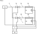
- FIG 2 shows a site having a source of cooling 1b instead of a heat source 1a.
- the source of cooling 1b is different from the heat source 1a.
- the source of cooling 1a and the heat source 1a are the same.
- a combined source of cooling 1b and heat source 1a can, by way of non-limiting example, comprise a heat pump.
- the source of cooling 1b advantageously comprises at least one of
- the source of cooling 1b comprises a mechanical heat pump and at least one of
- the source of cooling 1b operates the mechanical heat hump so long as the coefficient of performance of the mechanical heat pump is within acceptable limits. If the coefficient of performance of the mechanical heat pump is no longer within acceptable limits, the source of cooling 1b switches over to an alternate source selected from at least one of
- TABS thermally activated building structure
- a thermally activated building structure 6c, 6d forms at least one of
- the branches 2a - 2d are advantageously each different.
- the valves 3a - 3d are advantageously also each different.
- the space 4a - 4d and the sensors 5a - 5d are preferably each different.
- the system controller can also be arranged at a location that is remote from the site. Likewise, the system controller can be arranged at a location that is remote from the building.
- FIG 3 illustrates a system controller 8b that is arranged at a location that is remote from the temperature controller 7. It is envisaged that the system controller 8b is arranged at least one kilometre, preferably at least two kilometres, or even at least five kilometres from the temperature controller 7.
- the bidirectional connection between the system controller 8b and the temperature controller 7 can involve a connectionless datagram service such as the Internet Protocol.
- the bidirectional connection between the system controller 8b and the temperature controller 7 can also involve a connection-oriented transport layer protocol service such as the Transmission Control Protocol.
- system controller 8b comprises a cloud computer. In a special embodiment, the system controller 8b is a cloud computer.
- system controller 8a, 8b connects to a multitude of temperature controllers 7.
- the connections between the system controller 8a, 8b and the multitude of temperature controllers 7 involve bidirectional communications between pairs, each pair comprising the system controller 8a, 8b and a temperature controller 7.
- a system controller 8a, 8b can, by way of non-limiting example, orchestrate a fleet of similar sites.
- the sites can be similar in geographical location and/or in size and/or in structure.
- a system controller 8a, 8b can, by way of another non-limiting example, orchestrate a fleet of similar buildings.
- the buildings can be similar in geographical location and/or in size and/or in structure.
- the system controller 8a, 8b can cluster various spaces 4a - 4d of a site.
- the system controller 8a, 8b has thermal capacitances of the spaces 4a - 4d stored in its memory.
- the system controller 8a, 8b can then cluster spaces 4a - 4d with similar individual thermal capacitances.
- the system controller 8a, 8b can, by way of example, cluster spaces 4a - 4d where the individual thermal capacitances of such spaces 4a - 4d differ by less than twenty percent, by less than thirty percent, or by less than fifty percent.
- the system controller 8a, 8b can also start with a given number of clusters such as two clusters of three clusters or five clusters.
- the system controller 8a, 8b then clusters spaces 4a - 4d having similar individual thermal capacitances until it arrives at the predetermined number of clusters.
- a thermal capacitance is connected to the energy storage capacity and/or power storage capacity.
- a thermal capacitance ideally assumes no energy losses. It is defined as the amount of power necessary to change the temperature rate of a medium such as air by one unit in one second. More specifically, the thermal capacitance is the heat flow necessary to change the temperature rate of a medium such as air by one unit in one second.
- the unit of change can, by way of non-limiting example, be one Kelvin.
- the system controller 8a, 8b can also cluster various spaces 4a - 4d of a site based on typical usage.
- the system controller 8a, 8b has usages of the spaces 4a - 4d stored in its memory.
- the system controller 8a, 8b can then cluster spaces 4a - 4d with similar usages.
- the system controller 8a, 8b can also start with a given number of clusters such as two clusters of three clusters or five clusters.
- the system controller 8a, 8b then clusters spaces 4a - 4d having similar usages until it arrives at the predetermined number of clusters.
- the system controller 8a, 8b can cluster various rooms of a building.
- the system controller 8a, 8b has individual thermal capacitances of the rooms stored in its memory.
- the system controller 8a, 8b can then cluster rooms with similar individual thermal capacitances.
- the system controller 8a, 8b can, by way of example, cluster rooms where the individual thermal capacitances of such rooms differ by less than twenty percent, by less than thirty percent, or by less than fifty percent.
- the system controller 8a, 8b can also start with a given number of clusters such as two clusters of three clusters or five clusters.
- the system controller 8a, 8b then clusters rooms having similar individual thermal capacitances until it arrives at the predetermined number of clusters.
- the system controller 8a, 8b can also cluster various rooms of a building based on typical usage.
- the system controller 8a, 8b has usages of the rooms stored in its memory.
- the system controller 8a, 8b can then cluster rooms with similar usages.
- the system controller 8a, 8b can also start with a given number of clusters such as two clusters of three clusters or five clusters.
- the system controller 8a, 8b then clusters rooms having similar usages until it arrives at the predetermined number of clusters.
- the system controller 8a, 8b determines an effective temperature for each cluster of spaces 4a - 4d. To that end, the system controller 8a, 8b obtains temperature values of the spaces 4a - 4d. The temperature values are ideally obtained from the temperature controller 7.
- the system controller 8a, 8b can, by way of example, determine the effective temperature as an arithmetic average of the temperatures of the spaces 4a - 4d. In a special embodiment, the system controller 8a, 8b determines the effective temperature by calculating an arithmetic average of the temperatures of the spaces 4a - 4d.
- the system controller 8a, 8b can, by way of another example, determine the effective temperature by determining a weighted average of the temperatures of the spaces 4a - 4d. More specifically, the system controller 8a, 8b can load individual weights of the spaces 4a - 4d from its memory and employ the individual weights to determine the weighted average. In a special embodiment, the system controller 8a, 8b employs the individual weights to calculate the weighted average.
- the system controller 8a, 8b can also load individual thermal capacitances of the spaces 4a - 4d from its memory. The system controller 8a, 8b then produces individual weights from the individual thermal capacitances. The system controller 8a, 8b eventually employs the individual weights to determine the weighted average. In a special embodiment, the system controller 8a, 8b employs the individual weights to calculate the weighted average.
- the system controller 8a, 8b loads individual surface areas of the spaces 4a - 4d from its memory.
- the system controller 8a, 8b then produces individual weights from the individual surfaces areas.
- the system controller 8a, 8b eventually employs the individual weights to determine the weighted average.
- the system controller 8a, 8b employs the individual weights to calculate the weighted average.
- the system controller 8a, 8b loads individual building volumes of the spaces 4a - 4d from its memory.
- the system controller 8a, 8b then produces individual weights from the individual building volumes.
- the system controller 8a, 8b eventually employs the individual weights to determine the weighted average.
- the system controller 8a, 8b employs the individual weights to calculate the weighted average.
- the system controller 8a, 8b can likewise determine an effective temperature for each cluster of rooms. To that end, the system controller 8a, 8b obtains temperature values of the rooms. The temperature values are ideally obtained from the temperature controller 7.
- the system controller 8a, 8b can, by way of example, determine the effective temperature as an arithmetic average of the temperatures of the rooms. In a special embodiment, the system controller 8a, 8b determines the effective temperature by calculating an arithmetic average of the temperatures of the rooms.
- the system controller 8a, 8b can, by way of another example, determine the effective temperature by determining a weighted average of the temperatures of the rooms. More specifically, the system controller 8a, 8b can load individual weights of the rooms from its memory and employ the individual weights to determine the weighted average. In a special embodiment, the system controller 8a, 8b employs the individual weights to calculate the weighted average.
- the system controller 8a, 8b can also load individual thermal capacitances of the rooms from its memory.
- the system controller 8a, 8b then produces individual weights from the individual thermal capacitances.
- the system controller 8a, 8b eventually employs the individual weights to determine the weighted average.
- the system controller 8a, 8b employs the individual weights to calculate the weighted average.
- the system controller 8a, 8b loads individual surface areas of the rooms from its memory.
- the system controller 8a, 8b then produces individual weights from the individual surfaces areas.
- the system controller 8a, 8b eventually employs the individual weights to determine the weighted average.
- the system controller 8a, 8b employs the individual weights to calculate the weighted average.
- the system controller 8a, 8b loads individual building volumes of the rooms from its memory.
- the system controller 8a, 8b then produces individual weights from the individual building volumes.
- the system controller 8a, 8b eventually employs the individual weights to determine the weighted average.
- the system controller 8a, 8b employs the individual weights to calculate the weighted average.
- clustered spaces 4a - 4d of the site reduce inaccuracies caused by deviations of individual spaces 4a - 4d.
- clustered rooms of the building reduce inaccuracies caused by deviations of individual rooms.
- C c denotes a thermal capacitance for the cluster C .
- the system controller 8a, 8b has thermal capacitances of the spaces 4a - 4d of the cluster C stored in its memory.
- the system controller 8a, 8b adds the thermal capacitances of the spaces 4a - 4d of the cluster up to determine the thermal capacitance C c of the cluster C .
- the system controller 8a, 8b adds the thermal capacitances of the spaces 4a - 4d of the cluster C up to calculate the thermal capacitance C c of the cluster C .
- the system controller 8a, 8b can have thermal capacitances of the rooms of the cluster stored C in its memory.
- the system controller 8a, 8b adds the thermal capacitances of the rooms of the cluster C up to determine the thermal capacitance C c of the cluster C .
- the system controller 8a, 8b adds the thermal capacitances of the rooms of the cluster up to calculate the thermal capacitance C c of the cluster C .
- the system controller 8a, 8b has individual surface areas of the spaces 4a - 4d of the cluster stored in its memory.
- the system controller 8a, 8b adds the individual surface areas of the spaces 4a - 4d of the cluster C up to determine a total surface area of the cluster C .
- the system controller 8a, 8b ideally adds the individual surface areas of the spaces 4a - 4d of the cluster C up to calculate a total surface area of the cluster C .
- the system controller 8a, 8b estimates the thermal capacitance C c of the cluster C as a function of the total surface area.
- the system controller 8a, 8b determines the thermal capacitance C c of the cluster C as a function of the total surface area.
- the system controller 8a, 8b calculates the thermal capacitance C c of the cluster C as a function of the total surface area.
- the system controller 8a, 8b can have individual surface areas of the rooms of the cluster C stored in its memory.
- the system controller 8a, 8b adds the individual surface areas of the rooms of the cluster C up to determine a total surface area of the cluster C .
- the system controller 8a, 8b ideally adds the individual surface areas of the rooms of the cluster C up to calculate a total surface area of the cluster C .
- the system controller 8a, 8b then estimates the thermal capacitance C c of the cluster C as a function of the total surface area.
- the system controller 8a, 8b determines the thermal capacitance C c of the cluster C as a function of the total surface area.
- the system controller 8a, 8b calculates the thermal capacitance C c of the cluster C as a function of the total surface area.
- the system controller 8a, 8b has individual building volumes of the spaces 4a - 4d of the cluster stored in its memory.
- the system controller 8a, 8b adds the individual building volumes of the spaces 4a - 4d of the cluster C up to determine a total building volume of the cluster C .
- the system controller 8a, 8b ideally adds the individual building volumes of the spaces 4a - 4d of the cluster C up to calculate a total building volume of the cluster C .
- the system controller 8a, 8b then estimates the thermal capacitance C c of the cluster C as a function of the total building volume.
- system controller 8a, 8b determines the thermal capacitance C c of the cluster C as a function of the total building volume. In another special embodiment, the system controller 8a, 8b calculates the thermal capacitance C c of the cluster C as a function of the total building volume.
- the system controller 8a, 8b can have individual building volumes of the rooms of the cluster C stored in its memory.
- the system controller 8a, 8b adds the individual building volumes of the rooms of the cluster C up to determine a total building volume of the cluster C .
- the system controller 8a, 8b ideally adds the individual building volumes of the rooms of the cluster up to calculate a total building volume of the cluster C .
- the system controller 8a, 8b then estimates the thermal capacitance C c of the cluster C as a function of the total building volume.
- the system controller 8a, 8b determines the thermal capacitance C c of the cluster C as a function of the total building volume.
- the system controller 8a, 8b calculates the thermal capacitance C c of the cluster C as a function of the total building volume.
- the above thermal power balance also involves characteristic temperatures T c,t and T c,t +1 of the cluster C .
- the effective temperatures T c,t and T c,t +1 refer to a point in time t and to a next point in time t + 1 , respectively.
- the points in time for the temperatures T c,t and T c,t +1 are fifteen minutes apart.
- the points in time for the temperatures T c,t and T c,t +1 are four hours apart. That is, the time interval ⁇ t is four hours.
- the points in time for the temperatures T c,t and T c,t +1 are twelve hours apart. That is, the time interval ⁇ t is twelve hours.
- the points in time for the temperatures T c,t and T c,t +1 are twenty-four hours apart. That is, the time interval ⁇ t is twenty-four hours.
- the right-hand side of the thermal power balance involves a heating power Q ⁇ C , t heat .
- the heating power Q ⁇ C , t heat is a heating power of a cluster C and at a point in time t.
- Lower and upper limits apply to the heating power Q ⁇ C , t heat . These lower and upper limits are determined by the thermal energy exchangers such as room heaters in the cluster C .
- the system controller 8a, 8b stores values of the lower and upper limits of heating power Q ⁇ C , t heat in its memory.
- the memory of the system controller 8a, 8b stores values of lower and upper limits of heating power Q ⁇ C , t heat of the individual spaces 4a - 4d of the cluster C .
- the system controller 8a, 8b can thus estimate a lower limit of heating power Q ⁇ C , t heat by adding the lower limits of the individual spaces 4a - 4d of the cluster C up.
- the system controller 8a, 8b can determine a lower limit of heating power Q ⁇ C , t heat by adding the lower limits for the individual spaces 4a - 4d of the cluster C up.
- the system controller 8a, 8b can calculate a lower limit of heating power Q ⁇ C , t heat by adding the lower limits for the individual spaces 4a - 4d of the cluster C up.
- the system controller 8a, 8b can estimate an upper limit of heating power Q ⁇ C , t heat by adding the upper limits for the individual spaces 4a - 4d of the cluster C up.
- the system controller 8a, 8b can determine an upper limit of heating power Q ⁇ C , t heat by adding the upper limits for the individual spaces 4a - 4d of the cluster C up.
- the system controller 8a, 8b can calculate an upper limit of heating power Q ⁇ C , t heat by adding the upper limits for the individual spaces 4a - 4d of the cluster C up.
- the memory of the system controller 8a, 8b stores values of lower and upper limits of heating power Q ⁇ C , t heat of the individual rooms of the cluster C .
- the system controller 8a, 8b can thus estimate a lower limit of heating power Q ⁇ C , t heat by adding the lower limits for the individual rooms of the cluster C up.
- the system controller 8a, 8b can determine a lower limit of heating power Q ⁇ C , t heat by adding the lower limits for the individual rooms of the cluster C up.
- the system controller 8a, 8b can calculate a lower limit of heating power Q ⁇ C , t heat by adding the lower limits for the individual rooms of the cluster C up.
- the system controller 8a, 8b can estimate an upper limit of heating power Q ⁇ C , t heat by adding the upper limits for the individual rooms of the cluster C up.
- the system controller 8a, 8b can determine an upper limit of heating power Q ⁇ C , t heat by adding the upper limits for the individual rooms of the cluster C up.
- the system controller 8a, 8b can calculate an upper limit of heating power Q ⁇ C , t heat by adding the upper limits for the individual rooms of the cluster C up.
- the memory of the system controller 8a, 8b stores values of surface areas of the individual spaces 4a - 4d of the cluster C .
- the system controller 8a, 8b can thus estimate a lower limit of heating power Q ⁇ C , t heat from a sum of the surface areas of the individual spaces 4a - 4d of the cluster.
- the system controller 8a, 8b can determine a lower limit of heating power Q ⁇ C , t heat from a sum of the surface areas of the individual spaces 4a - 4d of the cluster.
- the system controller 8a, 8b can calculate a lower limit of heating power Q ⁇ C , t heat from a sum of the surface areas of the individual spaces 4a - 4d of the cluster. Likewise, the system controller 8a, 8b can estimate an upper limit of heating power Q ⁇ C , t heat from a sum of the surface areas of the cluster. In an embodiment, the system controller 8a, 8b can determine an upper limit of heating power Q ⁇ C , t heat from a sum of the surface areas of the cluster. In a special embodiment, the system controller 8a, 8b can calculate an upper limit of heating power Q ⁇ C , t heat from a sum of the surface areas of the individual spaces 4a - 4d of the cluster.
- the memory of the system controller 8a, 8b stores values of surface areas of the individual rooms of the cluster.
- the system controller 8a, 8b can thus estimate a lower limit of heating power Q ⁇ C , t heat from a sum of the surface areas of the individual rooms of the cluster.
- the system controller 8a, 8b can determine a lower limit of heating power Q ⁇ C , t heat from a sum of the surface areas of the individual rooms of the cluster.
- the system controller 8a, 8b can calculate a lower limit of heating power Q ⁇ C , t heat from a sum of the surface areas of the individual rooms of the cluster.
- the system controller 8a, 8b can estimate an upper limit of heating power Q ⁇ C , t heat from a sum of the surface areas of the cluster. In an embodiment, the system controller 8a, 8b can determine an upper limit of heating power Q ⁇ C , t heat from a sum of the surface areas of the cluster. In a special embodiment, the system controller 8a, 8b can calculate an upper limit of heating power Q ⁇ C , t heat from a sum of the surface areas of the individual rooms of the cluster.
- the memory of the system controller 8a, 8b stores values of building volumes for the individual spaces 4a - 4d of the cluster.
- the system controller 8a, 8b can thus estimate a lower limit of heating power Q ⁇ C , t heat from a sum of the building volumes of the individual spaces 4a - 4d of the cluster.
- the system controller 8a, 8b can determine a lower limit of heating power Q ⁇ C , t heat from a sum of the building volumes of the individual spaces 4a - 4d of the cluster.
- the system controller 8a, 8b can calculate a lower limit of heating power Q ⁇ C , t heat from a sum of the building volumes of the individual spaces 4a - 4d of the cluster.
- the system controller 8a, 8b can estimate an upper limit of heating power Q ⁇ C , t heat from a sum of the building volumes of the cluster.
- the system controller 8a, 8b can determine an upper limit of heating power Q ⁇ C , t heat from a sum of the building volumes of the cluster.
- the system controller 8a, 8b can calculate an upper limit of heating power Q ⁇ C , t heat from a sum of the building volumes of the individual spaces 4a - 4d of the cluster.
- the memory of the system controller 8a, 8b stores values of building volumes for the individual rooms of the cluster C .
- the system controller 8a, 8b can thus estimate a lower limit of heating power Q ⁇ C , t heat from a sum of the building volumes of the individual rooms of the cluster C .
- the system controller 8a, 8b can determine a lower limit of heating power Q ⁇ C , t heat from a sum of the building volumes of the individual rooms of the cluster C .
- the system controller 8a, 8b can calculate a lower limit of heating power Q ⁇ C , t heat from a sum of the building volumes of the individual rooms of the cluster C .
- the system controller 8a, 8b can estimate an upper limit of heating power Q ⁇ C , t heat from a sum of the building volumes of the cluster C .
- the system controller 8a, 8b can determine an upper limit of heating power Q ⁇ C , t heat from a sum of the building volumes of the cluster C .
- the system controller 8a, 8b can calculate an upper limit of heating power Q ⁇ C , t heat from a sum of the building volumes of the individual rooms of the cluster C .
- the right-hand side of the thermal power balance involves a cooling power Q ⁇ C , t cool .
- the cooling power Q ⁇ C , t cool is a cooling power of a cluster C and at a point in time t.
- Lower and upper limits apply to the cooling power Q ⁇ C , t cool . These lower and upper limits are determined by the thermal energy exchangers such as chilled beams in the cluster C .
- the system controller 8a, 8b stores values of the lower and upper limits of cooling power Q ⁇ C , t cool in its memory.
- the memory of the system controller 8a, 8b stores values of lower and upper limits of cooling power Q ⁇ C , t cool of the individual spaces 4a - 4d of the cluster C .
- the system controller 8a, 8b can thus estimate a lower limit of cooling power Q ⁇ C , t cool by adding the lower limits of the individual spaces 4a - 4d of the cluster C up.
- the system controller 8a, 8b can determine a lower limit of cooling power Q ⁇ C , t cool by adding the lower limits for the individual spaces 4a - 4d of the cluster C up.
- the system controller 8a, 8b can calculate a lower limit of cooling power Q ⁇ C , t cool by adding the lower limits for the individual spaces 4a - 4d of the cluster C up.
- the system controller 8a, 8b can estimate an upper limit of cooling power Q ⁇ C , t cool by adding the upper limits for the individual spaces 4a - 4d of the cluster C up.
- the system controller 8a, 8b can determine an upper limit of cooling power Q ⁇ C , t cool by adding the upper limits for the individual spaces 4a - 4d of the cluster C up.
- the system controller 8a, 8b can calculate an upper limit of cooling power Q ⁇ C , t cool by adding the upper limits for the individual spaces 4a - 4d of the cluster C up.
- the memory of the system controller 8a, 8b stores values of lower and upper limits of cooling power Q ⁇ C , t cool of the individual rooms of the cluster C .
- the system controller 8a, 8b can thus estimate a lower limit of cooling power Q ⁇ C , t cool by adding the lower limits for the individual rooms of the cluster C up.
- the system controller 8a, 8b can determine a lower limit of cooling power Q ⁇ C , t cool by adding the lower limits for the individual rooms of the cluster C up.
- the system controller 8a, 8b can calculate a lower limit of cooling power Q ⁇ C , t cool by adding the lower limits for the individual rooms of the cluster C up.
- the system controller 8a, 8b can estimate an upper limit of cooling power Q ⁇ C , t cool by adding the upper limits for the individual rooms of the cluster C up.
- the system controller 8a, 8b can determine an upper limit of cooling power Q ⁇ C , t cool by adding the upper limits for the individual rooms of the cluster C up.
- the system controller 8a, 8b can calculate an upper limit of cooling power Q ⁇ C , t cool by adding the upper limits for the individual rooms of the cluster C up.
- the memory of the system controller 8a, 8b stores values of surface areas of the individual spaces 4a - 4d of the cluster C .
- the system controller 8a, 8b can thus estimate a lower limit of cooling power Q ⁇ C , t cool from a sum of the surface areas of the individual spaces 4a - 4d of the cluster C .
- the system controller 8a, 8b can determine a lower limit of cooling power Q ⁇ C , t cool from a sum of the surface areas of the individual spaces 4a - 4d of the cluster C .
- the system controller 8a, 8b can calculate a lower limit of cooling power Q ⁇ C , t cool from a sum of the surface areas of the individual spaces 4a - 4d of the cluster C .
- the system controller 8a, 8b can estimate an upper limit of cooling power Q ⁇ C , t cool from a sum of the surface areas of the cluster C .
- the system controller 8a, 8b can determine an upper limit of cooling power Q ⁇ C , t cool from a sum of the surface areas of the cluster C .
- the system controller 8a, 8b can calculate an upper limit of cooling power Q ⁇ C , t cool from a sum of the surface areas of the individual spaces 4a - 4d of the cluster C .
- the memory of the system controller 8a, 8b stores values of surface areas of the individual rooms of the cluster C .
- the system controller 8a, 8b can thus estimate a lower limit of cooling power Q ⁇ C , t cool from a sum of the surface areas of the individual rooms of the cluster C .
- the system controller 8a, 8b can determine a lower limit of cooling power Q ⁇ C , t cool from a sum of the surface areas of the individual rooms of the cluster C .
- the system controller 8a, 8b can calculate a lower limit of cooling power Q ⁇ C , t cool from a sum of the surface areas of the individual rooms of the cluster C .
- the system controller 8a, 8b can estimate an upper limit of cooling power Q ⁇ C , t cool from a sum of the surface areas of the cluster C .
- the system controller 8a, 8b can determine an upper limit of cooling power Q ⁇ C , t cool from a sum of the surface areas of the cluster C .
- the system controller 8a, 8b can calculate an upper limit of cooling power Q ⁇ C , t cool from a sum of the surface areas of the individual rooms of the cluster C .
- the memory of the system controller 8a, 8b stores values of building volumes for the individual spaces 4a - 4d of the cluster C .
- the system controller 8a, 8b can thus estimate a lower limit of cooling power Q ⁇ C , t cool from a sum of the building volumes of the individual spaces 4a - 4d of the cluster C .
- the system controller 8a, 8b can determine a lower limit of cooling power Q ⁇ C , t cool from a sum of the building volumes of the individual spaces 4a - 4d of the cluster C .
- the system controller 8a, 8b can calculate a lower limit of cooling power Q ⁇ C , t cool from a sum of the building volumes of the individual spaces 4a - 4d of the cluster C .
- the system controller 8a, 8b can estimate an upper limit of cooling power Q ⁇ C , t cool from a sum of the building volumes of the cluster C .
- the system controller 8a, 8b can determine an upper limit of cooling power Q ⁇ C , t cool from a sum of the building volumes of the cluster C .
- the system controller 8a, 8b can calculate an upper limit of cooling power Q ⁇ C , t cool from a sum of the building volumes of the individual spaces 4a - 4d of the cluster C .
- the memory of the system controller 8a, 8b stores values of building volumes for the individual rooms of the cluster C .
- the system controller 8a, 8b can thus estimate a lower limit of cooling power Q ⁇ C , t cool from a sum of the building volumes of the individual rooms of the cluster C .
- the system controller 8a, 8b can determine a lower limit of cooling power Q ⁇ C , t cool from a sum of the building volumes of the individual rooms of the cluster C .
- the system controller 8a, 8b can calculate a lower limit of cooling power Q ⁇ C , t cool from a sum of the building volumes of the individual rooms of the cluster C .
- the system controller 8a, 8b can estimate an upper limit of cooling power Q ⁇ C , t cool from a sum of the building volumes of the cluster C .
- the system controller 8a, 8b can determine an upper limit of cooling power Q ⁇ C , t cool from a sum of the building volumes of the cluster C .
- the system controller 8a, 8b can calculate an upper limit of cooling power Q ⁇ C , t cool from a sum of the building volumes of the individual rooms of the cluster C .
- the right-hand side of the thermal power balance involves a demand for heat Q ⁇ C , t demand for heat .
- Q ⁇ C , t demand for heat is a demand for heat of a cluster C and at a point in time t.
- a demand for heat Q ⁇ C , t demand for heat is advantageously estimated from at least one of
- a demand for heat Q ⁇ C , t demand for heat is advantageously determined from at least one of
- a demand for heat Q ⁇ C , t demand for heat is advantageously calculated from at least one of
- the system controller 8a, 8b can also leverage its knowledge of the amount of sourced heating power Q ⁇ t heat source .
- the heat source 1a can, by way of example, send values of sourced heating power Q ⁇ t heat source to the system controller 8a, 8b.
- the heat source 1a can, by way of another example, send values of sourced heating power Q ⁇ t heat source to the temperature controller 7. The temperature controller 7 then sends these values to the system controller 8a, 8b.
- the site can also provide a buffer 9 as shown in FIG 4 .
- the buffer 9 preferably comprises a buffer for thermal power.
- the buffer 9 ideally is a buffer for thermal power.
- the buffer 9 can, by way of example, send values of buffered thermal power to the system controller 8a, 8b.
- the buffer 9 can, by way of another example, send values of buffered thermal power to the temperature controller 7. The temperature controller 7 then sends these values to the system controller 8a, 8b.
- the buffer 9 can also comprise a sensor such as a temperature sensor.
- the buffer 9 can, by way of example, record one or more signals indicative of temperature inside the buffer 9. The buffer 9 then sends these signals to the temperature controller 7.
- the temperature controller 7 is operable to produce one or more values of temperature inside the buffer 9 from the one or more signals received from the buffer 9.
- the temperature controller 7 is also operable to send the one or more values of temperature to the system controller 8a, 8b.
- the temperature controller 7 preferably uses a digital communication bus.
- the temperature controller 7 ideally uses a digital communication protocol to send the one or more values of temperature inside the buffer 9 to the system controller 8a, 8b.
- the temperature controller 7 is operable to produce values of thermal power buffered inside the buffer 9 from the one or more signals received from the buffer 9.
- the temperature controller 7 is also operable to send the one or more values of thermal power to the system controller 8a, 8b.
- the temperature controller 7 preferably uses a digital communication bus.
- the temperature controller 7 ideally uses a digital communication protocol to send the one or more values of buffered thermal power to the system controller 8a, 8b.
- the buffer 9 is in fluid communication with the heat source 1a. In an alternate embodiment, the buffer 9 is in fluid communication with the source of cooling 1b.
- the system controller 8a, 8b eventually estimates an overall demand for heat Q ⁇ t demand for heat based on the sourced heating power Q ⁇ t heat source and based on the one or more values of temperature inside the buffer 9. In a special embodiment, the overall demand for heat Q ⁇ t demand for heat is estimated based on the sourced heating power Q ⁇ t heat source and based on a time series of values of temperature inside the buffer 9.
- the system controller 8a, 8b can establish a thermal power balance for the buffer 9 as it estimates the overall demand for heat Q ⁇ t demand for heat .
- the system controller 8a, 8b can also use the thermal power balance for the buffer 9 as it estimates the overall demand for heat Q ⁇ t demand for heat .
- the system controller 8a, 8b estimates an overall demand for heat Q ⁇ t demand for heat based on the sourced heating power Q ⁇ t heat source and based on the one or more values of buffered thermal power.
- the overall demand for heat Q ⁇ t demand for heat is estimated based on the sourced heating power Q ⁇ t heat source and based on a time series of values of buffered thermal power.
- the system controller 8a, 8b can establish a thermal power balance for the buffer 9 as it estimates the overall demand for heat Q ⁇ t demand for heat .
- the system controller 8a, 8b can also use the thermal power balance for the buffer 9 as it estimates the overall demand for heat Q ⁇ t demand for heat .
- the thermal buffer 9 is in fluid communication with one or more valves 3e of a first cluster.
- the one or more valves 3e of the first cluster are in fluid communication with one or more thermally activated building structures 6e of the first cluster.
- the thermal buffer 9 is also in fluid communication with one or more valves 3f of a second cluster.
- the one or more valves 3f of the second cluster are in fluid communication with one or more thermally activated building structures 6f of the second cluster.
- the thermal buffer 9 is still in fluid communication with one or more valves 3g of a third cluster.
- the one or more valves 3g of the third cluster are in fluid communication with one or more thermally activated building structures 6g of the second cluster.
- the heat source 1a is in direct fluid communication with one or more valves 3e of a first cluster.
- the one or more valves 3e of the first cluster are in direct fluid communication with one or more thermally activated building structures 6e of the first cluster.
- the heat source 1a is also in direct fluid communication with one or more valves 3f of a second cluster.
- the one or more valves 3f of the second cluster are in direct fluid communication with one or more thermally activated building structures 6f of the second cluster.
- the heat source 1a is still in direct fluid communication with one or more valves 3g of a third cluster.
- the one or more valves 3g of the third cluster are in direct fluid communication with one or more thermally activated building structures 6g of the third cluster.
- the source of cooling 1b is in direct fluid communication with one or more valves 3e of a first cluster.
- the one or more valves 3e of the first cluster are in direct fluid communication with one or more thermally activated building structures 6e of the first cluster.
- the source of cooling 1b is also in direct fluid communication with one or more valves 3f of a second cluster.
- the one or more valves 3f of the second cluster are in direct fluid communication with one or more thermally activated building structures 6f of the second cluster.
- the source of cooling 1b is still in direct fluid communication with one or more valves 3g of a third cluster.
- the one or more valves 3g of the third cluster are in direct fluid communication with one or more thermally activated building structures 6g of the second cluster.
- delays between cooling and/or heating and consecutive changes in temperature are factored in.
- delays between cooling and/or heating and consecutive changes temperature can be determined by a temperature controller 7. That way, temperature controllers 7 can determine such delays for individual rooms of the building and/or for individual spaces 4a - 4d of the site. Temperature controllers 7 can also determine delays between cooling and/or heating and consecutive temperature changes for individual clusters of the site. Delays between cooling and/or heating and consecutive temperature changes can also be determined by a system controller 8a, 8b. That way, those delays can be determined for the entire site and/or for the entire building. In an embodiment with finer granularity, delays are determined by the system controller 8a, 8b per room and/or per space 4a - 4d and/or per cluster.
- Dedicated sensors can be available at the site such that values of cooling power Q ⁇ C , t cool and/or values of heating power Q ⁇ C , t heat can be obtained directly.
- a sensor can, for example, provide signals indicative of supply and return temperatures and of volume flow.
- a sensor for measurements of cooling power Q ⁇ C , t cool and/or of heating power Q ⁇ C , t heat becomes available, such values Q ⁇ C , t cool and/or Q ⁇ C , t heat no longer need to be estimated. Values of cooling power Q ⁇ C , t cool and/or values of heating power Q ⁇ C , t heat are then readily obtained from the signals of such sensors.
- EP3489591A1 filed on 18 October 2018 and claims a priority of an earlier application of 24 November 2017. The application was published on 29 May 2019.
- FIG 1 of EP3489591A1 illustrates sensors for measurements of cooling power and/or measurements of heating power.
- a least one cluster of the site comprises a sensor that affords direct measurements of cooling power Q ⁇ C , t cool and/or of heating power Q ⁇ C , t heat . It is also envisaged that all clusters of the site comprise a sensor that affords direct measurements of cooling power Q ⁇ C , t cool and/or of heating power Q ⁇ C , t heat . Sensors for direct measurements of cooling power Q ⁇ C , t cool and/or of heating power Q ⁇ C , t heat can be available throughout the site. In this case, values Q ⁇ C , t cool and/or Q ⁇ C , t heat no longer need to be estimated at all. Instead, the thermal power balance can be established based on values directly obtained from such sensors for the entire site.
- a least one space 4a - 4d of the building comprises a sensor that affords direct measurements of cooling power and/or of heating power. It is also envisaged that all spaces 4a - 4d of the building comprise a sensor that affords direct measurements of cooling power and/or of heating power. Sensors for direct measurements of cooling power and/or of heating power can be available throughout the building. In this case, values of cooling power and/or values of heating power no longer need to be estimated at all. Instead, the thermal power balance can be established based on values directly obtained from such sensors for all spaces 4a - 4d.
- a least one room of the building comprises a sensor that affords direct measurements of cooling power and/or of heating power. It is also envisaged that all rooms of the building comprise a sensor that affords direct measurements of cooling power and/or of heating power. Sensors for direct measurements of cooling power and/or of heating power can be available throughout the building. In this case, values of cooling power and/or values of heating power no longer need to be estimated at all. Instead, the thermal power balance can be established based on values directly obtained from these sensors for all rooms.
- a cluster of a site can have a sensor for direct measurements of cooling power Q ⁇ C , t cool and/or of heating power Q ⁇ C , t heat . If that sensor is complemented by a temperature sensor, correlations between the two sensors can be established. That way, faulted temperature sensors and/or faulted sensors for direct measurements of cooling power Q ⁇ C , t cool and/or of heating power Q ⁇ C , t heat can be identified. Also, measurements and/or values obtained from the signals of either type of sensor can be checked for plausibility.
- all clusters have a temperature sensor as well as a sensor for direct measurements of cooling power Q ⁇ C , t cool and/or of heating power Q ⁇ C , t heat . Identification of faulted sensors and/or plausibility checks are then available throughout the site.
- a space 4a - 4d of the site can have a sensor for direct measurements of cooling power and/or of heating power. If that sensor is complemented by a temperature sensor, correlations between the two sensors can be established. That way, faulted temperature sensors and/or faulted sensors for direct measurements of cooling power and/or of heating power can be identified. Also, measurements and/or values obtained from the signals of either type of sensor can be checked for plausibility. It is envisaged that all spaces 4a - 4d have a temperature sensor as well as a sensor for direct measurements of cooling power and/or of heating power. Identification of faulted sensors and/or plausibility checks are then available throughout the site.
- a room of the building can have a sensor for direct measurements of cooling power and/or of heating power. If that sensor is complemented by a temperature sensor, correlations between the two sensors can be established. That way, faulted temperature sensors and/or faulted sensors for direct measurements of cooling power and/or of heating power can be identified. Also, measurements and/or values obtained from the signals of either type of sensor can be checked for plausibility. It is envisaged that all rooms have a temperature sensor as well as a sensor for direct measurements of cooling power and/or of heating power. Identification of faulted sensors and/or plausibility checks are then available throughout the building.
- Positions of the valves 3a - 3g of the building or of the site need not always be available. More specifically, some positions of the valves 3a - 3g can be unavailable.
- the positions of valves 3a - 3g of refrigerant circuits of supermarkets can, by way of example, be unknown. More specifically, some positions of valves 3a - 3g of such a refrigerant circuit can be unknown.
- demands for cooling Q ⁇ C , t demand for cooling can be estimated based on comparisons between temperature values and set points indicative of temperature.
- the temperature values are preferably obtained from measured temperatures. Ideally, the temperature values are measured temperatures.
- the temperature values can also be effective temperatures of clusters as provided above.
- Demands for cooling Q ⁇ C , t demand for cooling are also estimated based on a control mode or based on an assumed mode of control.
- demands for heat Q ⁇ C , t demand for heat can be estimated based on comparisons between temperature values and set points indicative of temperature.
- the temperature values are preferably obtained from measured temperatures. Ideally, the temperature values are measured temperatures.
- the temperature values can also be effective temperatures of clusters as provided above.
- Demands for heat Q ⁇ C , t demand for hat are also estimated based on a control mode or based on an assumed mode of control.
- a first mode of operation assumes valves 3a - 3g with continuously or stepwise movable valve members. There is thus a plethora of valve positions between fully open and fully closed.
- a valve 3a - 3g is then gradually opened as a function of a difference between temperature values and set point temperatures. More specifically, the valve 3a - 3g is gradually opened as a function of a difference between measured temperature values and set point temperatures. The process of opening the valve 3a - 3g preferably continues until the valve 3a - 3g is in its fully open position.
- a second mode of operation assumes valves 3a - 3g without continuously movable valve members.
- the valves 3a - 3g of a building or of a site can be selectively movable between fully closed and fully open. That is, the valves 3a - 3g are either fully closed or fully open. No permanent or stationary valve position exists between fully closed and fully open. Control of the valves 3a - 3g is then limited to on-off control. More specifically, the temperature controller 7 employs on-off control to set fully closed or fully open positions of the valves 3a - 3g. Refrigerant circuits of supermarkets can, by way of non-limiting example, involve on-off control.
- a valve 3a - 3g will fully open as soon as a value of temperature is larger than an upper limit. More specifically, the valve 3a - 3g will fully open as soon as the measured value of temperature is larger than an upper limit. Likewise, the valve 3a - 3g will fully close as soon as the value of temperature or the effective temperature is less than a lower limit. More specifically, the valve 3a - 3g will fully close as soon as the measured value of temperature or the effective temperature is less than a lower limit.
- valves 3a - 3g of a cluster of a site can still apply to all the valves 3a - 3g of a space 4a - 4d of a site.
- same can still apply to all the valves 3a - 3g of a room of a building.
- a valve 3a - 3g will fully close as soon as a value of temperature is larger than an upper limit. More specifically, the valve 3a - 3g will fully close as soon as the measured value of temperature or the effective temperature is larger than an upper limit. Likewise, the valve 3a - 3g will fully open as soon as the value of temperature is less than a lower limit. More specifically, the valve 3a - 3g will fully open as soon as the measured value of temperature or the effective temperature is less than a lower limit.
- valves 3a - 3g of a cluster of a site can still apply to all the valves 3a - 3g of a space 4a - 4d of a site.
- same can still apply to all the valves 3a - 3g of a room of a building.
- the aforementioned on-off mode of control can also applied to buildings and/or to sites where details of available control modes are unavailable or not readily available.
- Demands for cooling Q ⁇ C , t demand for cooling can also be estimated based on reference measurements of thermal power over a predefined time period.
- demands for heat Q ⁇ C , t demand for heat can be estimated based on reference measurements of thermal power over a period of time.
- the period of time can, by way of non-limiting example, be four hours or twelve hours or twenty-four hours.
- an operator and/or a user can set the period of time for power measurements in accordance with the requirements of the building and/or of the site.
- the period of time is a predetermined period of time.
- the period of time increases with the capacity of the thermal heat exchanger and/or with the capacity of the storage device for thermal energy.
- the thermal heat exchanger can, by way of non-limiting example, comprise one or more thermally activated building structures 6a - 6g.
- the thermal heat exchanger is a thermally activated building structure 6a - 6g.
- the period of time then increases with the capacity of the thermally activated building structure 6a - 6g.
- the period of time can also increase with the thermal mass of the thermally activated building structure 6a - 6g.
- the system controller 8a, 8b controls thermal heat exchangers and/or a storage device based on such measurements of thermal power. That is, the system controller 8a, 8b causes supply of thermal power to the thermal heat exchangers and/or to the storage device in accordance with reference measurements of thermal power. In so doing, the system controller 8a, 8b factors in technical constraints of the thermal heat exchangers and/or of the storage device. The system controller 8a, 8b can also factor in technical constraints of a system for heating and/or ventilation and/or air-conditioning of the site. The system controller 8a, 8b can still factor in technical constraints of a system for heating and/or ventilation and/or air-conditioning of the building. The system controller 8a, 8b advantageously factors in technical constraints of the heat source 1a and/or technical constraints of the source of cooling 1b.
- system controller 8a, 8b directly controls the thermal heat exchangers and/or the storage device. In an alternate embodiment, the system controller 8a, 8b employs a temperature controller 7 to control the thermal heat exchangers and/or the storage device.
- the system controller 8a, 8b controls one or more thermally activated building structures 6a - 6g.
- the system controller 8a, 8b causes supply of thermal power to the one or more thermally activated building structures 6a - 6g in accordance with reference measurements of thermal power.
- the system controller 8a, 8b factors in technical constraints of the one or more thermally activated building structures 6a - 6g.
- the system controller 8a, 8b can also factor in technical constraints of a system for heating and/or ventilation and/or air-conditioning of the site.
- the system controller 8a, 8b can still factor in technical constraints of a system for heating and/or ventilation and/or air-conditioning of the building.
- the system controller 8a, 8b advantageously factors in technical constraints of the heat source 1a and/or technical constraints of the source of cooling 1b.
- system controller 8a, 8b directly controls the one or more thermally activated building structures 6a - 6g. In an alternate embodiment, the system controller 8a, 8b employs a temperature controller 7 to control the one or more thermally activated building structures 6a - 6g.
- the system controller 8a, 8b implements a neural network such as the network 11 shown in FIG 5 .
- the neural network 10 comprises a plurality of input neurons 11-17 associated with
- the neural network 10 comprises additional input neurons for historical values of
- the neural network 10 also comprises an output neuron 28 indicative of a cooling power Q ⁇ t cool and/or a heating power Q ⁇ t heat associated with a thermally activated building structure 6a - 6g.
- a value produced by output neuron is a set point for a thermally activated building structure 6a - 6g.
- the neural network 10 also comprises several hidden layers 18, 23, each layer 18, 23 having a number of hidden neurons 19 - 22, 24 - 27.
- the neural network 10 comprises a single layer of hidden neurons.
- the neural network 10 comprises two layers 18, 23 of hidden neurons.
- the neurons can, by way of non-limiting example, have sigmoid and/or hyperbolic tangent and/or stepwise activation and/or rectified exponential linear unit functions.
- the neurons 19 - 22, 24 - 28 are advantageously biased.
- the neural network 10 is ideally trained under test conditions. A series of measurements obtained under various test conditions is employed to train the network 10.
- the neural network 10 can, by way of example, be trained by a supervised training algorithm such as backpropagation. It is also envisaged that the neural network 10 is trained using an evolutionary algorithm such as a genetic algorithm. The skilled artisan can combine training algorithms. A genetic algorithm can, by way of example, be employed to find a coarse estimate of the weights of the connections of the neural network 10. A backpropagation algorithm is then employed to further improve on the performance of the neural network 10.
- the configuration of the neural network 10 and/or the weights of the connections of the neural network 10 are saved in a memory of or associated with the system controller 8a, 8b.
- the configuration of the neural network 10 and/or the weights of the connections of the neural network 10 then define how to control at least one of the thermally activated building structures 6a - 6g.
- the present disclosure teaches a method of controlling a site having a plurality of spaces (4a - 4d), at least one first space (4a - 4d) of the plurality of spaces (4a - 4d) having at least one thermal energy exchanger (6a - 6g), the at least one thermal energy exchanger (6a - 6g) having a predetermined thermal discharge characteristic, the method comprising the steps of:
- the method of controlling a site having a plurality of spaces (4a - 4d) is a method of controlling a comfort parameter at a site having a plurality of spaces (4a - 4d). It is also envisaged that the method of controlling a site having a plurality of spaces (4a - 4d) is a method of controlling at least one thermal energy exchanger (1) of a site having a plurality of spaces (4a - 4d).
- the at least one second space does not have at least one thermal energy exchanger (6a - 6g), the at least one thermal energy exchanger (6a - 6g) having a predetermined thermal discharge characteristic. That is, the at least one second space has at least one heat exchanger having a variable thermal discharge characteristic.
- the thermal discharge characteristic can, by way of example, vary because of a fan mounted to the heat exchanger.
- the fan advantageously is a variable speed fan.
- the fan can also be an on/off fan and the duty cycle of the on/off fan is controlled in accordance with varying thermal requirements.
- the system controller (8a, 8b) thus operates a site having heterogeneous heat exchangers.
- the at least one second space also has at least one thermal energy exchanger (6a - 6g), the at least one thermal energy exchanger (6a - 6g) having a predetermined thermal discharge characteristic.
- the system controller (8a, 8b) thus operates a site having homogeneous heat exchangers.
- the present disclosure further teaches any of the aforementioned methods, the method comprising the steps of:
- the first sensor (5a - 5d) is preferably different from the second sensor (5a - 5d).
- the present disclosure also teaches any of the aforementioned methods, the method comprising the steps of:
- the at least one first space (4a - 4d) is advantageously different from the at least one second space (4a - 4d).
- the comfort parameter ideally is a temperature, especially a room temperature.
- the first sensor (5a - 5d) preferably comprises a first temperature sensor (5a - 5d).
- the first sensor (5a - 5d) ideally is a first temperature sensor (5a - 5d).
- the second sensor (5a - 5d) preferably comprises a second temperature sensor (5a - 5d).
- the second sensor (5a - 5d) ideally is a second temperature sensor (5a - 5d).
- the present disclosure also deals with any of the aforementioned methods, the method comprising the step of: determining a first temperature difference of the at least one first space (4a - 4d) exclusively from the first time series of measured values and determining a second temperature difference of the at least one second space (4a - 4d) exclusively from the second time series of measured values.
- the instant disclosure still teaches any of the aforementioned methods, the method comprising the step of: calculating the first temperature difference of the at least one first space (4a - 4d) from the first time series of measured values and calculating the second temperature difference of the at least one second space (4a - 4d) from the second time series of measured values.
- the thermal power balance preferably comprises a system of mathematical relationships.
- the thermal power balance ideally is a system of mathematical relationships.
- the thermal power balance preferably comprises a system of equations.
- the thermal power balance ideally is a system of equations.
- the present disclosure also deals with any of the aforementioned methods, the method comprising the step of: setting up a thermal power balance of the site, the thermal power balance involving:
- the present disclosure further deals with any of the aforementioned methods, the method comprising the step of: establishing a thermal power balance of the site, the thermal power balance involving:
- the present disclosure also teaches any of the aforementioned methods, the method comprising the step of: determining a thermal power balance of the site, the thermal power balance involving:
- the instant disclosure still teaches any of the aforementioned methods, the method comprising the step of: calculating the thermal power balance of the site, the thermal power balance involving:
- the present disclosure further teaches any of the aforementioned methods, the method comprising the step of: determining the thermal power balance of the site, the thermal power balance comprising:
- the present disclosure still further teaches any of the aforementioned methods, the method comprising the step of: calculating the thermal power balance of the site, the thermal power balance comprising:
- the instant disclosure also teaches any of the aforementioned methods, the method comprising the step of: using the thermal power balance to calculate the cooling power Q ⁇ t cool and/or the heating power Q ⁇ t heat for the at least one first space (4a - 4d).
- the present disclosure further teaches any of the aforementioned methods, the method comprising the step of: solving the thermal power balance to determine the cooling power Q ⁇ t cool and/or the heating power Q ⁇ t heat for the at least one first space (4a - 4d).
- the instant disclosure still further teaches any of the aforementioned methods, the method comprising the step of: solving the thermal power balance to calculate the cooling power Q ⁇ t cool and/or the heating power Q ⁇ t heat for the at least one first space (4a - 4d).
- the present disclosure also teaches any of the aforementioned methods, the method comprising the step of: using the system of mathematical relationships to calculate the cooling power Q ⁇ t cool and/or the heating power Q ⁇ t heat for the at least one first space (4a - 4d).
- the instant disclosure further teaches any of the aforementioned methods, the method comprising the step of: solving the system of mathematical relationships to determine the cooling power Q ⁇ t cool and/or the heating power Q ⁇ t heat for the at least one first space (4a - 4d).
- the present disclosure further teaches any of the aforementioned methods, the method comprising the step of: solving the system of equations to determine the cooling power Q ⁇ t cool and/or the heating power Q ⁇ t heat for the at least one first space (4a - 4d).
- a flow of a coolant medium into the at least one thermal energy exchanger (6a - 6d) is produced as a function of the cooling power Q ⁇ t cool calculated for the at least one first space (4a - 4d). More specifically, a flow of a coolant medium into a conduit of the at least one thermal energy exchanger (6a - 6d) is produced as a function of the cooling power Q ⁇ t cool calculated for the at least one first space (4a - 4d).
- a flow of a coolant medium into the at least one thermal energy exchanger (6a - 6d) is produced as a function of the cooling power Q ⁇ t cool determined for the at least one first space (4a - 4d). More specifically, a flow of a coolant medium into a conduit of the at least one thermal energy exchanger (6a - 6d) is produced as a function of the cooling power Q ⁇ t cool determined for the at least one first space (4a - 4d).
- a flow of a heating medium into the at least one thermal energy exchanger (6a - 6d) is produced as a function of the heating power Q ⁇ t heat calculated for the at least one first space (4a - 4d). More specifically, a flow of a heating medium into a conduit of the at least one thermal energy exchanger (6a - 6d) is produced as a function of the heating power Q ⁇ t heat calculated for the at least one first space (4a - 4d).
- a flow of a heating medium into the at least one thermal energy exchanger (6a - 6d) is produced as a function of the heating power Q ⁇ t heat determined for the at least one first space (4a - 4d). More specifically, a flow of a heating medium into a conduit of the at least one thermal energy exchanger (6a - 6d) is produced as a function of the heating power Q ⁇ t heat determined for the at least one first space (4a - 4d).
- the present disclosure also teaches any of the aforementioned methods, wherein at least one of the first time series of signals and the second time series of signals comprises a time stamp for each signal, the method comprising the steps of:
- the instant disclosure also teaches any of the aforementioned methods involving the at least one time series of signals comprising the time stamp for each signal, the method comprising the steps of:
- the present disclosure further teaches any of the aforementioned methods involving the at least one time series of signals comprising the time stamp for each signal, the method comprising the steps of:
- the instant disclosure still further teaches any of the aforementioned methods involving the at least one time series of signals comprising the time stamp for each signal, the method comprising the steps of:
- the present disclosure still further teaches any of the aforementioned methods involving the at least one time series of signals comprising the time stamp for each signal, the method comprising the steps of:
- the instant disclosure also teaches any of the aforementioned methods involving the at least one time series of signals comprising the time stamp for each signal, the method comprising the steps of:
- the present disclosure further teaches any of the aforementioned methods involving the at least one time series of signals comprising the time stamp for each signal, the method comprising the steps of:
- the instant disclosure still further teaches any of the aforementioned methods involving the at least one time series of signals comprising the time stamp for each signal, the method comprising the steps of:
- the present disclosure also teaches any of the aforementioned methods, the method comprising the steps of:
- the instant disclosure also teaches any of the aforementioned methods involving the lower limit deviation, the method comprising the step of: calculating the lower limit deviation as a difference between the at least one measured value of the first time series of measured values and the lower limit value.
- a flow of a heated medium into the at least one thermal energy exchanger (6a - 6d) is produced exclusively as a function of the lower limit deviation. More specifically, a flow of a heated medium into a conduit of the at least one thermal energy exchanger (6a - 6d) is produced exclusively as a function of the lower limit deviation.
- the lower limit value is a predetermined lower limit value.
- the present disclosure also teaches any of the aforementioned methods, the method comprising the steps of:
- the instant disclosure also teaches any of the aforementioned methods involving the upper limit deviation, the method comprising the step of: calculating the upper limit deviation as a difference between the at least one measured value of the first time series of measured values and the upper limit value.
- a flow of a coolant medium into the at least one thermal energy exchanger (6a - 6d) is produced exclusively as a function of the upper limit deviation. More specifically, a flow of a coolant medium into a conduit of the at least one thermal energy exchanger (6a - 6d) is produced exclusively as a function of the upper limit deviation.
- the upper limit value is a predetermined upper limit value.
- the present disclosure also teaches any of the aforementioned methods, the method comprising the steps of:
- the thermal power balance preferably comprises a system of mathematical relationships.
- the thermal power balance ideally is a system of mathematical relationships.
- the thermal power balance preferably comprises a system of equations.
- the thermal power balance ideally is a system of equations.
- the instant disclosure also teaches any of the aforementioned methods involving the value of the thermal capacitance C of each space (4a - 4d) of the site, the method comprising the step of: calculating the thermal power balance of the site, the thermal power balance involving:
- the present disclosure further teaches any of the aforementioned methods involving the value of the thermal capacitance C of each space (4a - 4d) of the site, the method comprising the step of: determining the thermal power balance of the site, the thermal power balance comprising:
- the instant disclosure further teaches any of the aforementioned methods involving the value of the thermal capacitance C of each space (4a - 4d) of the site, the method comprising the step of: calculating the thermal power balance of the site, the thermal power balance involving:
- the present disclosure also teaches any of the aforementioned methods involving the plurality of time series of signals indicative of the comfort parameter, wherein at least one time series of the plurality of time series comprises a time stamp for each signal, the method comprising the steps of:
- the present disclosure also teaches any of the aforementioned methods involving the plurality of time series of signals indicative of the comfort parameter, wherein at least one time series of the plurality of time series comprises a time stamp for each signal, the method involving the steps of:
- the instant disclosure further teaches any of the aforementioned methods involving the plurality of time series of signals indicative of the comfort parameter, wherein at least one time series of the plurality of time series comprises a time stamp for each signal, the method involving the steps of:
- the present disclosure still further teaches any of the aforementioned methods involving the plurality of time series of signals indicative of the comfort parameter, wherein at least one time series of the plurality of time series comprises a time stamp for each signal, the method comprising the steps of:
- the present disclosure also teaches any of the aforementioned methods, the method comprising the steps of:
- the instant disclosure also teaches a method of controlling a site having a plurality of spaces (4a - 4d), at least one first space (4a - 4d) of the plurality of spaces (4a - 4d) having at least one thermal energy exchanger (6a - 6g), the at least one thermal energy exchanger (6a - 6g) having a predetermined thermal discharge characteristic, the method comprising the steps of:
- the instant disclosure also teaches any of the aforementioned methods involving the at least one first cluster, the method comprising the steps of:
- the present disclosure further teaches any of the aforementioned methods involving the at least one first cluster, the method comprising the steps of:
- the third sensor (5a - 5d) is preferably different from the fourth sensor (5a - 5d).
- the comfort parameter ideally is a temperature, especially a room temperature.
- the third sensor (5a - 5d) preferably comprises a third temperature sensor (5a - 5d).
- the third sensor (5a - 5d) ideally is a third temperature sensor (5a - 5d).
- the fourth sensor (5a - 5d) preferably comprises a fourth temperature sensor (5a - 5d).
- the fourth sensor (5a - 5d) ideally is a fourth temperature sensor (5a - 5d).
- the third sensor (5a - 5d) comprises the first temperature sensor (5a - 5d) and the second temperature sensor (5a - 5d).
- the present disclosure also teaches any of the aforementioned methods involving the at least one first cluster, the method comprising the steps of:
- the at least one first cluster is advantageously different from the at least one second cluster.
- the at least one first space (4a - 4d), the at least one second space (4a - 4d), the at least one third space (4a - 4d), and the at least one fourth space (4a - 4d) are ideally mutually different.
- the instant disclosure still teaches any of the aforementioned methods involving the at least one first cluster, the method comprising the step of: calculating the third temperature difference of the at least one first cluster from the third time series of measured values and calculating the fourth temperature difference of the at least one second cluster from the fourth time series of measured values.
- the instant disclosure also teaches any of the aforementioned methods involving the at least one first cluster, the method comprising the step of: calculating the thermal power balance of the site, the thermal power balance involving:
- the present disclosure further teaches any of the aforementioned methods involving the at least one first cluster, the method comprising the step of: determining the thermal power balance of the site, the thermal power balance comprising:
- the present disclosure still further teaches any of the aforementioned methods involving the at least one first cluster, the method comprising the step of: calculating the thermal power balance of the site, the thermal power balance comprising:
- the instant disclosure also teaches any of the aforementioned methods involving the at least one first cluster, the method comprising the step of: using the thermal power balance to calculate the cooling power Q ⁇ C , t cool and/or the heating power Q ⁇ C , t heat for the at least one first cluster.
- the present disclosure further teaches any of the aforementioned methods involving the at least one first cluster, the method comprising the step of: solving the thermal power balance to determine the cooling power Q ⁇ C , t cool and/or the heating power Q ⁇ C , t heat for the at least one first cluster.
- the instant disclosure still further teaches any of the aforementioned methods involving the at least one first cluster, the method comprising the step of: solving the thermal power balance to calculate the cooling power Q ⁇ C , t cool and/or the heating power Q ⁇ C , t heat for the at least one first cluster.
- the present disclosure also teaches any of the aforementioned methods involving the at least one first cluster, the method comprising the step of: using the system of mathematical relationships to calculate the cooling power Q ⁇ C , t cool and/or the heating power Q ⁇ C , t heat for the at least one first cluster.
- the instant disclosure further teaches any of the aforementioned methods involving the at least one first cluster, the method comprising the step of: solving the system of mathematical relationships to determine the cooling power Q ⁇ C , t cool and/or the heating power Q ⁇ C , t heat for the at least one first cluster.
- the present disclosure still further teaches any of the aforementioned methods involving the at least one first cluster, the method comprising the steps of:
- the instant disclosure also teaches any of the aforementioned methods involving the at least one first cluster, the method comprising the steps of:
- the present disclosure further teaches any of the aforementioned methods involving the at least one first cluster, the method comprising the step of: solving the system of equations to determine the cooling power Q ⁇ C , t cool and/or the heating power Q ⁇ C , t heat for the at least one first cluster.
- a flow of a coolant medium into the at least one thermal energy exchanger (6a - 6d) is produced as a function of the cooling power Q ⁇ C , t cool calculated for the at least one first cluster. More specifically, a flow of a coolant medium into a conduit of the at least one thermal energy exchanger (6a - 6d) is produced as a function of the cooling power Q ⁇ C , t cool calculated for the at least one first cluster.
- a flow of a coolant medium into the at least one thermal energy exchanger (6a - 6d) is produced as a function of the cooling power Q ⁇ C , t cool determined for the at least one first cluster. More specifically, a flow of a coolant medium into a conduit of the at least one thermal energy exchanger (6a - 6d) is produced as a function of the cooling power Q ⁇ C , t cool determined for the at least one first cluster.
- a flow of a heating medium into the at least one thermal energy exchanger (6a - 6d) is produced as a function of the heating power Q ⁇ C , t heat calculated for the at least one first cluster. More specifically, a flow of a heating medium into a conduit of the at least one thermal energy exchanger (6a - 6d) is produced as a function of the heating power Q ⁇ C , t heat calculated for the at least one first cluster.
- a flow of a heating medium into the at least one thermal energy exchanger (6a - 6d) is produced as a function of the heating power Q ⁇ C , t heat determined for the at least one first cluster. More specifically, a flow of a heating medium into a conduit of the at least one thermal energy exchanger (6a - 6d) is produced as a function of the heating power Q ⁇ C , t heat determined for the at least one first cluster.
- the present disclosure also teaches any of the aforementioned methods involving the at least one first cluster, the method comprising the steps of:
- the instant disclosure also teaches any of the aforementioned methods involving the at least one first cluster, the method comprising the steps of:
- the present disclosure also teaches any of the aforementioned methods involving the at least one first cluster, the method comprising the steps of:
- the instant disclosure also teaches any of the aforementioned methods involving the at least one first cluster, the method comprising the steps of:
- the present disclosure also teaches any of the aforementioned methods involving the at least one first cluster, the method comprising the steps of:
- the instant disclosure also teaches any of the aforementioned methods involving the at least one first cluster, the method comprising the steps of:
- the present disclosure also teaches any of the aforementioned methods involving the at least one first cluster, the method comprising the steps of:
- the instant disclosure also teaches any of the aforementioned methods involving the lower limit deviation and the at least one first cluster, the method comprising the step of: calculating the lower limit deviation as a difference between the at least one measured value of the third time series of measured values and the lower limit value.
- a flow of a heated medium into the at least one thermal energy exchanger (6a - 6d) is produced exclusively as a function of the lower limit deviation. More specifically, a flow of a heated medium into a conduit of the at least one thermal energy exchanger (6a - 6d) is produced exclusively as a function of the lower limit deviation.
- the lower limit value is a predetermined lower limit value.
- the instant disclosure also teaches a computer program comprising instructions which, when the program is executed by a computer, cause the computer to carry out the steps of any of the aforementioned methods.
- the instant disclosure also teaches a computer-readable medium comprising instructions which, when executed by a computer, cause the computer to carry out the steps of any of the aforementioned methods.
- the instant disclosure also teaches computer-readable data carrier having stored thereon any of aforementioned the computer programs.
- a system controller (8a, 8b) in operative communication with at least one thermal energy exchanger (6a - 6d) and in operative communication with a first sensor (5a - 5d) in at least one first space (4a - 4d) of a site and in operative communication with a second sensor (5a - 5d) in at least one second space (4a - 4d) of the site, the system controller (8a, 8b) having means adapted to execute the steps of any of the aforementioned methods.
- a computer program comprising instructions to cause the system controller (8a, 8b) to execute the steps of any of the aforementioned methods.
- a computer-readable medium having stored thereon the aforementioned computer program.
Landscapes
- Engineering & Computer Science (AREA)
- Physics & Mathematics (AREA)
- Remote Sensing (AREA)
- General Physics & Mathematics (AREA)
- Automation & Control Theory (AREA)
- Thermal Sciences (AREA)
- Chemical & Material Sciences (AREA)
- Combustion & Propulsion (AREA)
- Mechanical Engineering (AREA)
- General Engineering & Computer Science (AREA)
- Air Conditioning Control Device (AREA)
Claims (14)
- Procédé de régulation d'un site ayant une pluralité d'espaces (4a à 4d), au moins un premier espace (4a à 4d) de la pluralité d'espaces (4a à 4d) ayant au moins un échangeur d'énergie thermique (6a à 6g), le procédé comprenant les étapes de :l'acquisition d'une première série chronologique de signaux indicatifs d'un paramètre de confort dans au moins un premier espace (4a à 4d) du site ;l'acquisition d'une deuxième série chronologique de signaux indicatifs du paramètre de confort dans au moins un deuxième espace (4a à 4d) du site ;la production d'une première série chronologique de valeurs mesurées indicatives du paramètre de confort à partir de la première série chronologique de signaux ;la production d'une deuxième série chronologique de valeurs mesurées indicatives du paramètre de confort à partir de la deuxième série chronologique de signaux ;la détermination d'une première différence de température de l'au moins un premier espace (4a à 4d) à partir de la première série chronologique de valeurs mesurées et la détermination d'une deuxième différence de température de l'au moins un deuxième espace (4a à 4d) à partir de la deuxième série chronologique de valeurs mesurées ;l'utilisation d'un système d'équations établissant un équilibre de puissance thermique du site, le système d'équations impliquant :- une valeur d'une capacité thermique C de l'au moins un premier espace (4a à 4d) du site ;- une valeur d'une capacité thermique C de l'au moins un deuxième espace (4a à 4d) du site ;- une puissance de refroidissement

 - une puissance de refroidissement
 - la première différence de température et la deuxième différence de température ;pour déterminer la puissance de refroidissement
 caractérisé en ce quele système d'équations implique également- une demande en refroidissement
 - une demande en refroidissement
 et en ce quel'au moins un échangeur d'énergie thermique (6a à 6g) possède une caractéristique de rejet thermique prédéterminée ;et en ce que le système d'équations implique également la caractéristique de rejet thermique prédéterminée de l'au moins un échangeur d'énergie thermique (6a à 6d), la caractéristique de rejet prédéterminée étant une relation mathématique indicative d'un rejet thermique en fonction du temps ou une formule indicative d'un rejet thermique en fonction du temps ;et en ce que le procédé comprend l'étape de :
la charge de l'au moins un échangeur d'énergie thermique (6a à 6g) avec de l'énergie thermique en fonction de la puissance de refroidissement

- Le procédé selon l'une quelconque de la revendication 1, dans lequel au moins l'une de la première série chronologique de signaux et de la deuxième série chronologique de signaux comprend un horodatage pour chaque signal, le procédé comprenant les étapes de :la détermination d'une différence temporelle entre deux horodatages consécutifs de l'au moins une série chronologique de signaux ; etl'utilisation du système d'équations du site, le système d'équations impliquant en outre :- la différence temporelle déterminée.
- Le procédé selon l'une quelconque des revendications 1 à 2, le procédé comprenant les étapes de :la comparaison d'au moins une valeur mesurée de la première série chronologique de valeurs mesurées avec une valeur de limite inférieure ;si l'au moins une valeur mesurée de la première série chronologique de valeurs mesurées est inférieure à la valeur de limite inférieure :la détermination d'un écart de limite inférieure comme étant une différence entre l'au moins une valeur mesurée de la première série chronologique de valeurs mesurées et la valeur de limite inférieure ; etla charge de l'au moins un échangeur d'énergie thermique (6a à 6d) avec de l'énergie thermique exclusivement en fonction de l'écart de limite inférieure.
- Le procédé selon l'une quelconque des revendications 1 à 3, le procédé comprenant les étapes de :la comparaison d'au moins une valeur mesurée de la première série chronologique de valeurs mesurées avec une valeur de limite supérieure ;si l'au moins une valeur mesurée de la première série chronologique de valeurs mesurées est supérieure à la valeur de limite supérieure :la détermination d'un écart de limite supérieure comme étant une différence entre l'au moins une valeur mesurée de la première série chronologique de valeurs mesurées et la valeur de limite supérieure ; etla charge de l'au moins un échangeur d'énergie thermique (6a à 6d) avec de l'énergie thermique exclusivement en fonction de l'écart de limite supérieure.
- Le procédé selon l'une quelconque des revendications 1 à 4, le procédé comprenant les étapes de :l'acquisition d'une pluralité de séries chronologiques de signaux indicatifs du paramètre de confort, chaque série chronologique étant associée au paramètre de confort dans un espace (4a à 4d) de la pluralité d'espaces (4a à 4d) du site ;la production d'une pluralité de séries chronologiques de valeurs mesurées à partir de la pluralité de séries chronologiques de signaux ;l'utilisation de la pluralité de séries chronologiques de valeurs mesurées pour déterminer une différence de température de chaque espace (4a à 4d) ;l'utilisation du système d'équations du site, le système d'équations impliquant :- une valeur d'une capacité thermique C de chaque espace (4a à 4d) du site ;- une demande en refroidissement
 - une puissance de refroidissement
 - une différence de température de chaque espace (4a à 4d) du site ; et- la caractéristique de rejet thermique prédéterminée de l'au moins un échangeur d'énergie thermique (6a à 6d).
 - Le procédé selon la revendication 5, dans lequel au moins une série chronologique de la pluralité de séries chronologiques comprend un horodatage pour chaque signal, le procédé comprenant les étapes de :la détermination d'une différence temporelle entre deux horodatages consécutifs de l'au moins une série chronologique de signaux ; etl'utilisation du système d'équations du site, le système d'équations impliquant en outre :- la différence temporelle déterminée.
- Le procédé selon l'une quelconque des revendications 1 à 6, le procédé comprenant les étapes de :la formation d'au moins un premier regroupement comprenant l'au moins un premier espace (4a à 4d) et l'au moins un deuxième espace (4a à 4d) ;la formation d'au moins un second regroupement comprenant au moins un troisième espace (4a à 4d) de la pluralité d'espaces (4a à 4d) et au moins un quatrième espace (4a à 4d) de la pluralité d'espaces (4a à 4d) ;l'acquisition d'une troisième série chronologique de signaux indicatifs du paramètre de confort dans l'au moins un premier regroupement ;l'acquisition d'une quatrième série chronologique de signaux indicatifs du paramètre de confort dans l'au moins un second regroupement ;la production d'une troisième série chronologique de valeurs mesurées indicatives du paramètre de confort à partir de la troisième série chronologique de signaux ;la production d'une quatrième série chronologique de valeurs mesurées indicatives du paramètre de confort à partir de la quatrième série chronologique de signaux ;la détermination d'une troisième différence de température de l'au moins un premier regroupement à partir de la troisième série chronologique de valeurs mesurées et la détermination d'une quatrième différence de température de l'au moins un second regroupement à partir de la quatrième série chronologique de valeurs mesurées ;l'utilisation du système d'équations du site, le système d'équations impliquant :- une valeur d'une capacité thermique Cc de l'au moins un premier regroupement ;- une valeur d'une capacité thermique Cc de l'au moins un second regroupement ;- une demande en refroidissement

 - une demande en refroidissement
 - une puissance de refroidissement
 - une puissance de refroidissement
 - la troisième différence de température et la quatrième différence de température ;- la caractéristique de rejet thermique prédéterminée de l'au moins un échangeur d'énergie thermique (6a à 6d) ;pour déterminer la puissance de refroidissement
 la charge de l'au moins un échangeur d'énergie thermique (6a à 6g) avec de l'énergie thermique en fonction de la puissance de refroidissement
- Le procédé selon la revendication 7, le procédé comprenant les étapes de :la détermination de la valeur de la capacité thermique Cc de l'au moins un premier regroupement par l'addition de la valeur de la capacité thermique C de l'au moins un premier espace (4a à 4d) et de la valeur de la capacité thermique C de l'au moins un deuxième espace (4a à 4d) ; etla détermination de la valeur de la capacité thermique Cc de l'au moins un second regroupement par l'addition d'une valeur d'une capacité thermique C de l'au moins un troisième espace (4a à 4d) et d'une valeur d'une capacité thermique C de l'au moins un quatrième espace (4a à 4d).
- Le procédé selon l'une quelconque des revendications 7 à 8, le procédé comprenant les étapes de :la détermination de la demande en refroidissement


 la détermination de la demande en refroidissement


- Le procédé selon l'une quelconque des revendications 7 à 8, le procédé comprenant les étapes de :la détermination de la demande en chauffage


 la détermination de la demande en chauffage

- Le procédé selon l'une quelconque des revendications 7 à 10, le procédé comprenant les étapes de :la comparaison d'au moins une valeur mesurée de la troisième série chronologique de valeurs mesurées avec une valeur de limite inférieure ;si l'au moins une valeur mesurée de la troisième série chronologique de valeurs mesurées est inférieure à la valeur de limite inférieure :la détermination d'un écart de limite inférieure comme étant une différence entre l'au moins une valeur mesurée de la troisième série chronologique de valeurs mesurées et la valeur de limite inférieure ; etla charge de l'au moins un échangeur d'énergie thermique (6a à 6d) avec de l'énergie thermique exclusivement en fonction de l'écart de limite inférieure.
- Programme d'ordinateur comprenant des instructions qui, lorsque le programme est exécuté par un ordinateur, amènent l'ordinateur à effectuer les étapes de l'un quelconque des procédés des revendications 1 à 11.
- Support lisible par ordinateur comprenant des instructions qui, lors de leur exécution par un ordinateur, amènent l'ordinateur à effectuer les étapes de l'un quelconque des procédés des revendications 1 à 11.
- Vecteur de données lisible par ordinateur ayant, stocké sur celui-ci, le programme d'ordinateur de la revendication 12.
Applications Claiming Priority (1)
| Application Number | Priority Date | Filing Date | Title |
|---|---|---|---|
| EP21171787 | 2021-05-03 |
Publications (2)
| Publication Number | Publication Date |
|---|---|
| EP4086724A1 EP4086724A1 (fr) | 2022-11-09 |
| EP4086724B1 true EP4086724B1 (fr) | 2023-10-18 |
Family
ID=75786955
Family Applications (1)
| Application Number | Title | Priority Date | Filing Date |
|---|---|---|---|
| EP21203882.2A Active EP4086724B1 (fr) | 2021-05-03 | 2021-10-21 | Réglage du refroidissement et/ou du chauffage |
Country Status (1)
| Country | Link |
|---|---|
| EP (1) | EP4086724B1 (fr) |
Families Citing this family (1)
| Publication number | Priority date | Publication date | Assignee | Title |
|---|---|---|---|---|
| CN120909389B (zh) * | 2025-10-11 | 2025-12-16 | 青岛恒丰作物科学有限公司 | 一种农药生产控制系统及方法 |
Family Cites Families (7)
| Publication number | Priority date | Publication date | Assignee | Title |
|---|---|---|---|---|
| NL1025309C2 (nl) | 2004-01-23 | 2005-07-26 | Nedap Nv | Systeem voor het onafhankelijk regelen van de temperaturen in verschillende ruimten en van de temperaturen van één of meerdere warmwaterboilers. |
| EP2993640A1 (fr) | 2014-09-08 | 2016-03-09 | Siemens Aktiengesellschaft | Système de gestion de l'alimentation |
| US11789415B2 (en) | 2016-06-30 | 2023-10-17 | Johnson Controls Tyco IP Holdings LLP | Building HVAC system with multi-level model predictive control |
| EP3489591B1 (fr) | 2017-11-24 | 2021-09-01 | Siemens Schweiz AG | Échangeur d'énergie thermique intelligent |
| WO2019129800A1 (fr) | 2017-12-31 | 2019-07-04 | Vito Nv | Robinet de radiateur ou de convecteur thermostatique intelligent destiné à un système de chauffage, et procédé de commande associé |
| EP3584555B1 (fr) | 2018-06-19 | 2020-05-27 | Siemens Aktiengesellschaft | Calorimètre de flux |
| EP3748458B1 (fr) | 2019-06-03 | 2021-04-28 | Siemens Schweiz AG | Organe de commande de dispositif de stockage thermique |
-
2021
- 2021-10-21 EP EP21203882.2A patent/EP4086724B1/fr active Active
Also Published As
| Publication number | Publication date |
|---|---|
| EP4086724A1 (fr) | 2022-11-09 |
Similar Documents
| Publication | Publication Date | Title |
|---|---|---|
| Joe et al. | A model predictive control strategy to optimize the performance of radiant floor heating and cooling systems in office buildings | |
| CN109063925B (zh) | 一种计及负荷聚合商的区域综合能源系统优化运行方法 | |
| US11268726B2 (en) | Air handling unit and rooftop unit with predictive control | |
| EP0699316B1 (fr) | Appareil de commande de chauffage | |
| CN104279715B (zh) | 一种楼宇空调设备负荷预测方法 | |
| EP2660942B1 (fr) | Procédé de planification du fonctionnement | |
| EP3196559A1 (fr) | Système de pompe à chaleur optimisé | |
| CN104319766B (zh) | 一种楼宇空调设备供电及监控方法 | |
| EP3196558A1 (fr) | Système de pompe à chaleur à double température | |
| CN104269940B (zh) | 一种楼宇空调设备负荷监控系统 | |
| EP3699720A1 (fr) | Système d'équilibrage dynamique d'une charge thermique et procédé associé | |
| US11530833B2 (en) | Systems and methods for controlling and predicting heat load disturbances | |
| US20180173171A1 (en) | Microgrid system and controller | |
| US20170250539A1 (en) | Cloud-based control for power distribution system | |
| KR101075893B1 (ko) | 지역난방시스템의 열에너지 공급 제어방법 | |
| WO2015183678A1 (fr) | Procédé et appareil pour des charges sélectives pouvant être commandées thermostatiques fractionnées en composantes | |
| CN105190193B (zh) | 空调控制装置、空调控制系统和空调控制方法 | |
| WO2019129800A1 (fr) | Robinet de radiateur ou de convecteur thermostatique intelligent destiné à un système de chauffage, et procédé de commande associé | |
| CN113390126A (zh) | 一种基于室温反馈的热力站在线动态调控装置及方法 | |
| JP2020165642A (ja) | 空調システム、サーバシステム、ネットワーク、空調システムを制御する方法、およびネットワークを制御する方法 | |
| EP4086724B1 (fr) | Réglage du refroidissement et/ou du chauffage | |
| KR101571806B1 (ko) | 공기조화시스템의 무인 최적제어 방법 | |
| CN111928428B (zh) | 一种考虑需求响应的空调系统的控制方法及制冷系统 | |
| KR101077255B1 (ko) | 대표세대 모니터링에 의한 열에너지 공급방법 | |
| CN111193261A (zh) | 一种基于建筑等效热储能的多能流系统日前优化方法 |
Legal Events
| Date | Code | Title | Description |
|---|---|---|---|
| STAA | Information on the status of an ep patent application or granted ep patent |
Free format text: STATUS: EXAMINATION IS IN PROGRESS |
|
| PUAI | Public reference made under article 153(3) epc to a published international application that has entered the european phase |
Free format text: ORIGINAL CODE: 0009012 |
|
| 17P | Request for examination filed |
Effective date: 20220405 |
|
| AK | Designated contracting states |
Kind code of ref document: A1 Designated state(s): AL AT BE BG CH CY CZ DE DK EE ES FI FR GB GR HR HU IE IS IT LI LT LU LV MC MK MT NL NO PL PT RO RS SE SI SK SM TR |
|
| GRAP | Despatch of communication of intention to grant a patent |
Free format text: ORIGINAL CODE: EPIDOSNIGR1 |
|
| STAA | Information on the status of an ep patent application or granted ep patent |
Free format text: STATUS: GRANT OF PATENT IS INTENDED |
|
| INTG | Intention to grant announced |
Effective date: 20230711 |
|
| GRAS | Grant fee paid |
Free format text: ORIGINAL CODE: EPIDOSNIGR3 |
|
| GRAA | (expected) grant |
Free format text: ORIGINAL CODE: 0009210 |
|
| STAA | Information on the status of an ep patent application or granted ep patent |
Free format text: STATUS: THE PATENT HAS BEEN GRANTED |
|
| AK | Designated contracting states |
Kind code of ref document: B1 Designated state(s): AL AT BE BG CH CY CZ DE DK EE ES FI FR GB GR HR HU IE IS IT LI LT LU LV MC MK MT NL NO PL PT RO RS SE SI SK SM TR |
|
| REG | Reference to a national code |
Ref country code: GB Ref legal event code: FG4D |
|
| REG | Reference to a national code |
Ref country code: CH Ref legal event code: EP |
|
| P01 | Opt-out of the competence of the unified patent court (upc) registered |
Effective date: 20230927 |
|
| REG | Reference to a national code |
Ref country code: DE Ref legal event code: R096 Ref document number: 602021005987 Country of ref document: DE |
|
| REG | Reference to a national code |
Ref country code: IE Ref legal event code: FG4D |
|
| REG | Reference to a national code |
Ref country code: SE Ref legal event code: TRGR |
|
| REG | Reference to a national code |
Ref country code: LT Ref legal event code: MG9D |
|
| REG | Reference to a national code |
Ref country code: NL Ref legal event code: MP Effective date: 20231018 |
|
| PG25 | Lapsed in a contracting state [announced via postgrant information from national office to epo] |
Ref country code: NL Free format text: LAPSE BECAUSE OF FAILURE TO SUBMIT A TRANSLATION OF THE DESCRIPTION OR TO PAY THE FEE WITHIN THE PRESCRIBED TIME-LIMIT Effective date: 20231018 |
|
| PG25 | Lapsed in a contracting state [announced via postgrant information from national office to epo] |
Ref country code: GR Free format text: LAPSE BECAUSE OF FAILURE TO SUBMIT A TRANSLATION OF THE DESCRIPTION OR TO PAY THE FEE WITHIN THE PRESCRIBED TIME-LIMIT Effective date: 20240119 |
|
| PG25 | Lapsed in a contracting state [announced via postgrant information from national office to epo] |
Ref country code: IS Free format text: LAPSE BECAUSE OF FAILURE TO SUBMIT A TRANSLATION OF THE DESCRIPTION OR TO PAY THE FEE WITHIN THE PRESCRIBED TIME-LIMIT Effective date: 20240218 |
|
| PG25 | Lapsed in a contracting state [announced via postgrant information from national office to epo] |
Ref country code: LT Free format text: LAPSE BECAUSE OF FAILURE TO SUBMIT A TRANSLATION OF THE DESCRIPTION OR TO PAY THE FEE WITHIN THE PRESCRIBED TIME-LIMIT Effective date: 20231018 |
|
| PG25 | Lapsed in a contracting state [announced via postgrant information from national office to epo] |
Ref country code: ES Free format text: LAPSE BECAUSE OF FAILURE TO SUBMIT A TRANSLATION OF THE DESCRIPTION OR TO PAY THE FEE WITHIN THE PRESCRIBED TIME-LIMIT Effective date: 20231018 |
|
| PG25 | Lapsed in a contracting state [announced via postgrant information from national office to epo] |
Ref country code: LT Free format text: LAPSE BECAUSE OF FAILURE TO SUBMIT A TRANSLATION OF THE DESCRIPTION OR TO PAY THE FEE WITHIN THE PRESCRIBED TIME-LIMIT Effective date: 20231018 Ref country code: IS Free format text: LAPSE BECAUSE OF FAILURE TO SUBMIT A TRANSLATION OF THE DESCRIPTION OR TO PAY THE FEE WITHIN THE PRESCRIBED TIME-LIMIT Effective date: 20240218 Ref country code: GR Free format text: LAPSE BECAUSE OF FAILURE TO SUBMIT A TRANSLATION OF THE DESCRIPTION OR TO PAY THE FEE WITHIN THE PRESCRIBED TIME-LIMIT Effective date: 20240119 Ref country code: ES Free format text: LAPSE BECAUSE OF FAILURE TO SUBMIT A TRANSLATION OF THE DESCRIPTION OR TO PAY THE FEE WITHIN THE PRESCRIBED TIME-LIMIT Effective date: 20231018 Ref country code: BG Free format text: LAPSE BECAUSE OF FAILURE TO SUBMIT A TRANSLATION OF THE DESCRIPTION OR TO PAY THE FEE WITHIN THE PRESCRIBED TIME-LIMIT Effective date: 20240118 Ref country code: PT Free format text: LAPSE BECAUSE OF FAILURE TO SUBMIT A TRANSLATION OF THE DESCRIPTION OR TO PAY THE FEE WITHIN THE PRESCRIBED TIME-LIMIT Effective date: 20240219 |
|
| PG25 | Lapsed in a contracting state [announced via postgrant information from national office to epo] |
Ref country code: RS Free format text: LAPSE BECAUSE OF FAILURE TO SUBMIT A TRANSLATION OF THE DESCRIPTION OR TO PAY THE FEE WITHIN THE PRESCRIBED TIME-LIMIT Effective date: 20231018 Ref country code: PL Free format text: LAPSE BECAUSE OF FAILURE TO SUBMIT A TRANSLATION OF THE DESCRIPTION OR TO PAY THE FEE WITHIN THE PRESCRIBED TIME-LIMIT Effective date: 20231018 Ref country code: NO Free format text: LAPSE BECAUSE OF FAILURE TO SUBMIT A TRANSLATION OF THE DESCRIPTION OR TO PAY THE FEE WITHIN THE PRESCRIBED TIME-LIMIT Effective date: 20240118 Ref country code: LV Free format text: LAPSE BECAUSE OF FAILURE TO SUBMIT A TRANSLATION OF THE DESCRIPTION OR TO PAY THE FEE WITHIN THE PRESCRIBED TIME-LIMIT Effective date: 20231018 Ref country code: HR Free format text: LAPSE BECAUSE OF FAILURE TO SUBMIT A TRANSLATION OF THE DESCRIPTION OR TO PAY THE FEE WITHIN THE PRESCRIBED TIME-LIMIT Effective date: 20231018 |
|
| REG | Reference to a national code |
Ref country code: BE Ref legal event code: MM Effective date: 20231031 |
|
| PG25 | Lapsed in a contracting state [announced via postgrant information from national office to epo] |
Ref country code: LU Free format text: LAPSE BECAUSE OF NON-PAYMENT OF DUE FEES Effective date: 20231021 |
|
| PG25 | Lapsed in a contracting state [announced via postgrant information from national office to epo] |
Ref country code: LU Free format text: LAPSE BECAUSE OF NON-PAYMENT OF DUE FEES Effective date: 20231021 |
|
| PG25 | Lapsed in a contracting state [announced via postgrant information from national office to epo] |
Ref country code: DK Free format text: LAPSE BECAUSE OF FAILURE TO SUBMIT A TRANSLATION OF THE DESCRIPTION OR TO PAY THE FEE WITHIN THE PRESCRIBED TIME-LIMIT Effective date: 20231018 |
|
| REG | Reference to a national code |
Ref country code: DE Ref legal event code: R097 Ref document number: 602021005987 Country of ref document: DE |
|
| PG25 | Lapsed in a contracting state [announced via postgrant information from national office to epo] |
Ref country code: CZ Free format text: LAPSE BECAUSE OF FAILURE TO SUBMIT A TRANSLATION OF THE DESCRIPTION OR TO PAY THE FEE WITHIN THE PRESCRIBED TIME-LIMIT Effective date: 20231018 |
|
| PG25 | Lapsed in a contracting state [announced via postgrant information from national office to epo] |
Ref country code: SK Free format text: LAPSE BECAUSE OF FAILURE TO SUBMIT A TRANSLATION OF THE DESCRIPTION OR TO PAY THE FEE WITHIN THE PRESCRIBED TIME-LIMIT Effective date: 20231018 |
|
| PG25 | Lapsed in a contracting state [announced via postgrant information from national office to epo] |
Ref country code: SM Free format text: LAPSE BECAUSE OF FAILURE TO SUBMIT A TRANSLATION OF THE DESCRIPTION OR TO PAY THE FEE WITHIN THE PRESCRIBED TIME-LIMIT Effective date: 20231018 Ref country code: SK Free format text: LAPSE BECAUSE OF FAILURE TO SUBMIT A TRANSLATION OF THE DESCRIPTION OR TO PAY THE FEE WITHIN THE PRESCRIBED TIME-LIMIT Effective date: 20231018 Ref country code: RO Free format text: LAPSE BECAUSE OF FAILURE TO SUBMIT A TRANSLATION OF THE DESCRIPTION OR TO PAY THE FEE WITHIN THE PRESCRIBED TIME-LIMIT Effective date: 20231018 Ref country code: IT Free format text: LAPSE BECAUSE OF FAILURE TO SUBMIT A TRANSLATION OF THE DESCRIPTION OR TO PAY THE FEE WITHIN THE PRESCRIBED TIME-LIMIT Effective date: 20231018 Ref country code: EE Free format text: LAPSE BECAUSE OF FAILURE TO SUBMIT A TRANSLATION OF THE DESCRIPTION OR TO PAY THE FEE WITHIN THE PRESCRIBED TIME-LIMIT Effective date: 20231018 Ref country code: DK Free format text: LAPSE BECAUSE OF FAILURE TO SUBMIT A TRANSLATION OF THE DESCRIPTION OR TO PAY THE FEE WITHIN THE PRESCRIBED TIME-LIMIT Effective date: 20231018 Ref country code: CZ Free format text: LAPSE BECAUSE OF FAILURE TO SUBMIT A TRANSLATION OF THE DESCRIPTION OR TO PAY THE FEE WITHIN THE PRESCRIBED TIME-LIMIT Effective date: 20231018 |
|
| PLBE | No opposition filed within time limit |
Free format text: ORIGINAL CODE: 0009261 |
|
| STAA | Information on the status of an ep patent application or granted ep patent |
Free format text: STATUS: NO OPPOSITION FILED WITHIN TIME LIMIT |
|
| PG25 | Lapsed in a contracting state [announced via postgrant information from national office to epo] |
Ref country code: MC Free format text: LAPSE BECAUSE OF FAILURE TO SUBMIT A TRANSLATION OF THE DESCRIPTION OR TO PAY THE FEE WITHIN THE PRESCRIBED TIME-LIMIT Effective date: 20231018 |
|
| PG25 | Lapsed in a contracting state [announced via postgrant information from national office to epo] |
Ref country code: MC Free format text: LAPSE BECAUSE OF FAILURE TO SUBMIT A TRANSLATION OF THE DESCRIPTION OR TO PAY THE FEE WITHIN THE PRESCRIBED TIME-LIMIT Effective date: 20231018 Ref country code: BE Free format text: LAPSE BECAUSE OF NON-PAYMENT OF DUE FEES Effective date: 20231031 |
|
| 26N | No opposition filed |
Effective date: 20240719 |
|
| PG25 | Lapsed in a contracting state [announced via postgrant information from national office to epo] |
Ref country code: IE Free format text: LAPSE BECAUSE OF NON-PAYMENT OF DUE FEES Effective date: 20231021 |
|
| PG25 | Lapsed in a contracting state [announced via postgrant information from national office to epo] |
Ref country code: SI Free format text: LAPSE BECAUSE OF FAILURE TO SUBMIT A TRANSLATION OF THE DESCRIPTION OR TO PAY THE FEE WITHIN THE PRESCRIBED TIME-LIMIT Effective date: 20231018 |
|
| PG25 | Lapsed in a contracting state [announced via postgrant information from national office to epo] |
Ref country code: SI Free format text: LAPSE BECAUSE OF FAILURE TO SUBMIT A TRANSLATION OF THE DESCRIPTION OR TO PAY THE FEE WITHIN THE PRESCRIBED TIME-LIMIT Effective date: 20231018 Ref country code: IE Free format text: LAPSE BECAUSE OF NON-PAYMENT OF DUE FEES Effective date: 20231021 |
|
| PGFP | Annual fee paid to national office [announced via postgrant information from national office to epo] |
Ref country code: CH Payment date: 20250114 Year of fee payment: 4 |
|
| PG25 | Lapsed in a contracting state [announced via postgrant information from national office to epo] |
Ref country code: FI Free format text: LAPSE BECAUSE OF FAILURE TO SUBMIT A TRANSLATION OF THE DESCRIPTION OR TO PAY THE FEE WITHIN THE PRESCRIBED TIME-LIMIT Effective date: 20231019 |
|
| PG25 | Lapsed in a contracting state [announced via postgrant information from national office to epo] |
Ref country code: CY Free format text: LAPSE BECAUSE OF FAILURE TO SUBMIT A TRANSLATION OF THE DESCRIPTION OR TO PAY THE FEE WITHIN THE PRESCRIBED TIME-LIMIT; INVALID AB INITIO Effective date: 20211021 |
|
| REG | Reference to a national code |
Ref country code: AT Ref legal event code: UEP Ref document number: 1623004 Country of ref document: AT Kind code of ref document: T Effective date: 20231018 |
|
| PG25 | Lapsed in a contracting state [announced via postgrant information from national office to epo] |
Ref country code: TR Free format text: LAPSE BECAUSE OF FAILURE TO SUBMIT A TRANSLATION OF THE DESCRIPTION OR TO PAY THE FEE WITHIN THE PRESCRIBED TIME-LIMIT Effective date: 20231018 |
|
| PGFP | Annual fee paid to national office [announced via postgrant information from national office to epo] |
Ref country code: GB Payment date: 20251111 Year of fee payment: 5 |
|
| PGFP | Annual fee paid to national office [announced via postgrant information from national office to epo] |
Ref country code: AT Payment date: 20260113 Year of fee payment: 5 |
|
| REG | Reference to a national code |
Ref country code: CH Ref legal event code: U11 Free format text: ST27 STATUS EVENT CODE: U-0-0-U10-U11 (AS PROVIDED BY THE NATIONAL OFFICE) Effective date: 20260114 |
|
| PGFP | Annual fee paid to national office [announced via postgrant information from national office to epo] |
Ref country code: FR Payment date: 20251020 Year of fee payment: 5 |
|
| PGFP | Annual fee paid to national office [announced via postgrant information from national office to epo] |
Ref country code: SE Payment date: 20251013 Year of fee payment: 5 |
|
| PG25 | Lapsed in a contracting state [announced via postgrant information from national office to epo] |
Ref country code: HU Free format text: LAPSE BECAUSE OF FAILURE TO SUBMIT A TRANSLATION OF THE DESCRIPTION OR TO PAY THE FEE WITHIN THE PRESCRIBED TIME-LIMIT; INVALID AB INITIO Effective date: 20211021 |
|
| PGFP | Annual fee paid to national office [announced via postgrant information from national office to epo] |
Ref country code: DE Payment date: 20251219 Year of fee payment: 5 |