EP4086874A1 - Procédé et appareil de commande pour un véhicule intelligent, et dispositif associé - Google Patents
Procédé et appareil de commande pour un véhicule intelligent, et dispositif associé Download PDFInfo
- Publication number
- EP4086874A1 EP4086874A1 EP21744507.1A EP21744507A EP4086874A1 EP 4086874 A1 EP4086874 A1 EP 4086874A1 EP 21744507 A EP21744507 A EP 21744507A EP 4086874 A1 EP4086874 A1 EP 4086874A1
- Authority
- EP
- European Patent Office
- Prior art keywords
- image
- collection
- collection device
- period
- duration
- Prior art date
- Legal status (The legal status is an assumption and is not a legal conclusion. Google has not performed a legal analysis and makes no representation as to the accuracy of the status listed.)
- Pending
Links
Images


Classifications
-
- G—PHYSICS
- G08—SIGNALLING
- G08G—TRAFFIC CONTROL SYSTEMS
- G08G1/00—Traffic control systems for road vehicles
- G08G1/09—Arrangements for giving variable traffic instructions
- G08G1/095—Traffic lights
-
- H—ELECTRICITY
- H04—ELECTRIC COMMUNICATION TECHNIQUE
- H04N—PICTORIAL COMMUNICATION, e.g. TELEVISION
- H04N23/00—Cameras or camera modules comprising electronic image sensors; Control thereof
- H04N23/70—Circuitry for compensating brightness variation in the scene
- H04N23/73—Circuitry for compensating brightness variation in the scene by influencing the exposure time
-
- G—PHYSICS
- G06—COMPUTING OR CALCULATING; COUNTING
- G06V—IMAGE OR VIDEO RECOGNITION OR UNDERSTANDING
- G06V10/00—Arrangements for image or video recognition or understanding
- G06V10/10—Image acquisition
- G06V10/12—Details of acquisition arrangements; Constructional details thereof
- G06V10/14—Optical characteristics of the device performing the acquisition or on the illumination arrangements
- G06V10/147—Details of sensors, e.g. sensor lenses
-
- G—PHYSICS
- G06—COMPUTING OR CALCULATING; COUNTING
- G06V—IMAGE OR VIDEO RECOGNITION OR UNDERSTANDING
- G06V20/00—Scenes; Scene-specific elements
- G06V20/50—Context or environment of the image
- G06V20/56—Context or environment of the image exterior to a vehicle by using sensors mounted on the vehicle
- G06V20/58—Recognition of moving objects or obstacles, e.g. vehicles or pedestrians; Recognition of traffic objects, e.g. traffic signs, traffic lights or roads
- G06V20/582—Recognition of moving objects or obstacles, e.g. vehicles or pedestrians; Recognition of traffic objects, e.g. traffic signs, traffic lights or roads of traffic signs
-
- G—PHYSICS
- G08—SIGNALLING
- G08G—TRAFFIC CONTROL SYSTEMS
- G08G1/00—Traffic control systems for road vehicles
- G08G1/09—Arrangements for giving variable traffic instructions
- G08G1/0962—Arrangements for giving variable traffic instructions having an indicator mounted inside the vehicle, e.g. giving voice messages
- G08G1/09623—Systems involving the acquisition of information from passive traffic signs by means mounted on the vehicle
Definitions
- This application relates to the computer field, and in particular, to an intelligent vehicle control method and apparatus and a related device.
- intelligent vehicles have become a new trend of vehicle development, and systems such as driver assistance (driver assistance), automated driving (automated driving), or intelligent network driving (intelligent network driving) are more frequently used in the vehicles.
- driver assistance driver assistance
- automated driving automated driving
- intelligent network driving intelligent network driving
- Such systems sense an ambient environment in a driving process by using image collection devices and vehicle-mounted sensors such as radars.
- Accuracy of sensing surrounding obstacles and the infrastructure by the intelligent vehicle affects planning and control of the intelligent vehicle.
- Recognition of a signal identifier (for example, a traffic light) on an electronic display apparatus is a key step in implementing automated driving of the intelligent vehicle.
- the electronic display apparatus is periodically turned on and off in a working process.
- the image collection device collects an image
- the electronic display apparatus may be in an off state in the collected image. Therefore, a recognition result of the intelligent vehicle to recognize the signal identifier based on the collected image is inconsistent with a result actually indicated by the electronic display apparatus (a result observed by human eyes). Therefore, how to provide a more accurate signal identifier recognition method to control the intelligent vehicle based on the recognition result becomes an urgent technical problem to be resolved.
- This application discloses an intelligent vehicle control method and apparatus and a related device.
- the method can increase a probability that a recognition result obtained based on an image collected by an image collection device is consistent with a result actually indicated by a signal identifier, to further improve accuracy and security of controlling an intelligent vehicle based on the recognition result.
- this application provides an intelligent vehicle control method.
- the method includes: A controller calculates target values of collection parameters of an image collection device in an intelligent vehicle when the controller recognizes a display apparatus for a signal identifier, where the collection parameters of the image collection device are used to indicate a collection period, a quantity of exposure times, exposure duration, and exposure interval duration that are of the image collection device to collect an image; the controller sends an adjustment instruction to the image collection device, where the adjustment instruction indicates the image collection device to adjust the collection parameters based on target values of collection parameters in the adjustment instruction; and the controller recognizes the signal identifier based on an image obtained after the image collection device adjusts the collection parameters, and controls driving of the intelligent vehicle based on the recognized signal identifier.
- the controller calculates the target values of the collection parameters of the image collection device, and adjusts collection parameters of the image collected by the image collection device, to increase a quantity of exposure times when the image collection device collects one image, and increase a probability that exposure time of the image collection device overlaps time when a traffic light is on. This increases a probability that the traffic light is in an on state in the image collected by the image collection device, and increases a probability that a recognition result obtained by the controller based on the image is consistent with a result actually indicated by the signal identifier, to further improve accuracy and security of controlling the intelligent vehicle based on the recognition result.
- the controller may be a controller in a mobile data center (mobile data center, MDC) in the vehicle.
- MDC mobile data center
- that the controller calculates the target values of the collection parameters of the image collection device in the intelligent vehicle when the controller recognizes the display apparatus for the signal identifier includes: The controller obtains an image obtained before the image collection device adjusts the collection parameters, and performs signal identifier detection on the image obtained before the image collection device adjusts the collection parameters, and the controller calculates the target values of the collection parameters of the image collection device in the intelligent vehicle when detecting the signal identifier; or the controller obtains a distance between the intelligent vehicle and the display apparatus, and the controller calculates the target values of the collection parameters of the image collection device in the intelligent vehicle when the distance is less than or equal to a preset distance, where the display apparatus is located in a heading direction along which the intelligent vehicle is driven.
- the controller determines, based on the image collected by the image collection device or the distance between the display apparatus and the intelligent vehicle, whether the image collection device can collect an image displaying the display apparatus.
- the controller starts to calculate the target values of the collection parameters and generate the adjustment instruction, to further adjust the collection parameters of the image collection device. Because the adjustment instruction is used to increase a quantity of exposure times of the image collection device to collect one image or a frequency of collecting an image, only when the image collection device can collect an image, the adjustment is performed, to reduce a workload of the image collection device.
- that the controller calculates the target values of the collection parameters of the image collection device in the intelligent vehicle includes: The controller obtains an on/off period of the display apparatus and duration in which the signal identifier is on in an on/off period, where the on/off period includes duration in which the signal identifier is on and duration in which the signal identifier is off; the controller determines the on/off period to be a collection period obtained after the image collection device adjusts the collection parameters, where the collection period is duration taken by the image collection device to collect one image; the controller determines, based on the collection period obtained after the image collection device adjusts the collection parameters, total exposure duration of the image collection device in one collection period, and the duration in which the signal identifier is on in one on/off period, a quantity of exposure times in one collection period obtained after the image collection device adjusts the collection parameters; the controller determines, based on the total exposure duration in one collection period and the quantity of exposure times in one collection period that are obtained after the image collection device adjusts the collection parameters, duration of each exposure obtained after
- the collection period of the image collection device is adjusted to be equal to the on/off period of the display apparatus, and the exposure interval duration is less than duration in which the display apparatus is on in one on/off period. It can be ensured that exposure time of at least one of a plurality of exposures of the image collection device in one collection period overlaps time at which the traffic light is on, and the traffic light is in an on state in each image collected by the image collection device.
- the quantity of exposure times in one collection period is specifically a quantity of exposure times in one collection period that is determined according to the following formula after the image collection device adjusts the collection parameters: (T2-T 2b )/n ⁇ T on and n ⁇ T2/T on , where n is the quantity of exposure times in one collection period after the image collection device adjusts the collection parameters, T2 is the collection period obtained after the image collection device adjusts the collection parameters, T 2b is the total exposure duration in one collection period obtained after the image collection device adjusts the collection parameters, and t on indicates the duration in which the signal identifier is on in one on/off period.
- the signal identifier is the traffic light
- that the controller recognizes the signal identifier based on the image obtained after the image collection device adjusts the collection parameters, and controls driving of the intelligent vehicle based on the recognized signal identifier includes: The controller recognizes the traffic light based on the image obtained after the image collection device adjusts the collection parameters, to obtain a recognition result, where the recognition result includes a red light, a green light, an amber light, and an unknown state, and a recognition result corresponding to each image is any one of the red light, the green light, the amber light, and the unknown state; and the controller determines, based on the recognition result and a previously determined status of the traffic light, a status of the traffic light in the image obtained after the image collection device adjusts the collection parameters, where the status of the traffic light includes the red light, the green light, and the amber light, and a status of the traffic light corresponding to each image is any one of the red light, the green light, and the amber light.
- this application provides an intelligent vehicle control apparatus, where the apparatus includes modules configured to perform the intelligent vehicle control method in the first aspect or any possible implementation of the first aspect.
- this application provides a computing device, including a processor and a memory, where the memory is configured to store instructions, the processor is configured to execute the instructions, and when executing the instructions, the processor performs the method described in the first aspect or any specific implementation of the first aspect.
- this application provides a non-transient computer-readable storage medium, where the computer-readable storage medium stores a computer program, and when the computer program is executed by a computing device, the method described in the first aspect or any specific implementation of the first aspect is performed.
- this application provides a computer program product including instructions.
- the computer program product is run on a computer, the computer is enabled to perform the method described in the foregoing aspects.
- a display apparatus for example, a light emitting diode (light emitting diode, LED) display
- the display apparatus is periodically turned on or off.
- the display apparatus is on for a period of time and then turned off for a period of time, and then turned on for another period of time and turned off for another period of time. Duration in which the display apparatus is on each time is the same, and duration in which the display apparatus is off each time is the same.
- a sum of duration in which the display apparatus is on once and duration in which the display apparatus is off once is referred to as an on/off period of the display apparatus.
- the on/off period of the display apparatus is 1/60 s to 20 ms (millisecond, ms), that is, the on/off frequency of the display apparatus is 50 Hz (Hertz, Hz) to 60 Hz.
- Duration in which the display apparatus is on in one on/off period usually accounts for 10% to 20% of the on/off period. For example, if the on/off period of the display apparatus is 20 ms, in one on/off period, duration in which the display apparatus is on is 2 ms to 4 ms, and duration in which the display apparatus is off is 16 ms to 18 ms.
- the signal identifier includes prompt information displayed on the display apparatus that is periodically turned on or off.
- the prompt information includes but is not limited to a traffic light, and a traffic prompt with a text or a symbol.
- a vehicle-mounted image collection device collects an image of the display apparatus, to determine an identifier displayed on the display apparatus.
- the image collection device needs to obtain the image of the display apparatus through an exposure.
- the exposure is a process in which light emitted or reflected by a photographed object is projected onto a negative or a photosensitive element by using a lens of the image collection device, and is imaged on the negative or the photosensitive element.
- Duration taken by the image collection device to collect one image is one collection period.
- the collection period includes exposure duration and exposure interval duration.
- the exposure duration is duration from time when a shutter of the image collection device is turned on to time when the shutter of the image collection device is turned off. The image collection device completes one exposure process within the exposure duration.
- the exposure interval duration is duration that elapses after the shutter of the image collection device is closed once and before the shutter of the image collection device is opened next time. For example, if a collection frequency at which the image collection device collects an image is 30, it indicates that the image collection device collects 30 images per second, and a collection period corresponding to each image is 33.33 ms, where the exposure duration is 10 ms and the exposure interval duration is 23.33 ms.
- the collection frequency indicates a quantity of images collected by the image collection device per second.
- a detection and recognition system based on machine vision is an indispensable part of the intelligent vehicle.
- the intelligent vehicle collects an image of an ambient environment in a driving process and analyzes the image by using the vehicle-mounted image collection device, to implement perception of the ambient environment of the vehicle in the driving process.
- This provides reliable data for the intelligent vehicle.
- a controller of a vehicle-mounted mobile data center detects and recognizes, based on the image collected by the image collection device, an identifier displayed on the display apparatus such as a traffic light, a traffic sign (left turn and right turn), and a speed limiting sign, and then controls driving of the intelligent vehicle based on a recognition result.
- the display apparatus is periodically turned on or off
- the display apparatus and the image collection device are two different devices, and a trigger time point at which the display apparatus is on and a trigger time point at which the image collection device performs the exposure cannot be synchronously controlled, exposure time at which the image collection device collects an image does not overlap time at which the display apparatus is on. Therefore, in the image collected by the image collection device, the display apparatus is in an off state.
- a current display apparatus is designed for recognition by human eyes, and visual persistence effect of the human eyes is considered.
- a result to be actually indicated by the display apparatus is consistent with a recognition result of the human eyes.
- the display apparatus is periodically turned on or off, because the on/off period is relatively short, a recognition result of the human eye is that the display apparatus is in an on state.
- a recognition result obtained by the controller based on the image collected by the image collection device may be inconsistent with a result actually indicated by the display apparatus. If the controller of the MDC controls driving of the intelligent vehicle based on the recognition result of the collected image, the intelligent vehicle may violate a traffic rule or even encounter a safety accident.
- this application provides the intelligent vehicle control method.
- collection parameters of the image collection device are dynamically adjusted, to effectively recognize a signal identifier displayed on the display apparatus, where the collection parameters include a collection period, a quantity of exposure times, exposure duration, and exposure interval duration that are of the image collection device to collect one image.
- the image collection device on the intelligent vehicle can collect a signal identifier image on the display apparatus, by increasing the quantity of exposure times of the image collection device to collect one image, or a collection frequency of the image collection device to collect an image and the quantity of exposure times of collecting one image, a time interval between two adjacent exposures of the image collection device is shortened, and an overlapping proportion between exposure time of the image collection device and time at which the signal identifier is on is increased.
- This increases a proportion that the signal identifier is in an on state in the image collected by the image collection device, and increases a probability that a recognition result of the controller is the same as a result actually indicated by the signal identifier, so that safety of the intelligent vehicle is improved.
- the collection parameters of the image collection device are adjusted to collection parameters of the image collection device when the image collection device cannot collect the signal identifier image on the display apparatus.
- FIG. 1 is a diagram of a system architecture of an intelligent vehicle provided in this application.
- the intelligent vehicle 10 includes a controller 110, an image collection device 120, a communication box 130, and a positioning module 140.
- the image collection device 120, the communication box 130, and the positioning module 140 are all communicatively connected to the controller 110.
- the controller communicates with a cloud service data center or another device by using the communication box 130 and a network.
- FIG. 2 is a schematic flowchart of an intelligent vehicle control method provided in this application. The method includes S201 to S205.
- S201 The controller 110 recognizes the traffic light.
- that the controller 110 recognizes the traffic light means that the controller recognizes whether the traffic light exists in an image collected by the image collection device 120.
- the image collection device collects an image at a first collection frequency and sends the collected image to the controller 110, and the controller 110 performs traffic light detection on the received image, to determine whether the traffic light exists in the image. If the traffic light exists in the image, the controller 110 performs S202; or if the traffic light does not exist in the image, the controller 110 continues to receive an image sent by the image collection device 120 and performs traffic light detection.
- the controller 110 recognizing the traffic light means recognizing a distance between the traffic light and the intelligent vehicle 10, to determine, based on the distance, whether the traffic light exists in the image collected by the image collection device 120.
- the controller 110 may determine, based on location information of the intelligent vehicle provided by the positioning module 140 and map data, whether the traffic light can be detected in the image collected by the image collection device 120.
- the map data includes location information of the traffic light.
- the controller 110 obtains current location information of the intelligent vehicle provided by the positioning module 140 and location information of the traffic light on a driving route in the map data, and determines a distance between the intelligent vehicle and a nearest traffic light on the driving route.
- the controller 110 determines that the traffic light can be detected in the image collected by the image collection device 120.
- the preset distance may be a distance, for example, 50 m, 100 m, or 200 m, between the image collection device 120 and a target object when the target object is distinctly recognized based on the image collected by the image collection device 120. This is not specifically limited in this embodiment of this application.
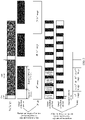
- a collection period of the image collection device 120 to collect one image is a first collection period T1 and the image collection device 120 collects one image through one exposure.
- a quantity of first exposure times of the image collection device 120 is 1, exposure duration of the image collection device 120 to collect one image is first exposure duration t 1b , and exposure interval duration is first exposure interval duration t 1g .
- the first collection frequency at which the image collection device 120 collects an image is 30, the first collection period is 33.33 ms, where the first exposure duration may be 10 ms, and the first exposure interval duration is 23.33 ms.
- S202 The controller 110 generates adjustment instruction and sends the adjustment instruction to the image collection device 120.
- the controller 110 obtains display parameters of a display apparatus displaying the traffic light.
- the display parameters include an on/off period of the display apparatus and duration in which the traffic light is on in each on/off period.
- the controller 110 calculates collection parameters based on the display parameters of the display apparatus, generates the adjustment instruction based on the collection parameters, and sends the adjustment instruction to the image collection device 120.
- the adjustment instruction indicates the image collection device 120 to adjust a current value of each collection parameter to a value corresponding to each collection parameter in the adjustment instruction.
- the collection parameters include a collection period, a quantity of exposure times, exposure duration, and exposure interval duration.
- the adjustment instruction includes a second collection period T 2 , a quantity n of second exposure times, second exposure duration t 2b , and second exposure interval duration t 2g that are of the image collection device 120.
- the quantity of exposure times indicates a quantity of exposure times of the image collection device 120 to collect one image.
- the quantity n of second exposure times is a positive integer greater than 1, and the quantity n of second exposure times indicates a quantity of exposure times needed by the image collection device 120 to collect one image after the image collection device adjusts the collection parameters according to the adjustment instruction.
- the second exposure duration t 2b indicates duration of each exposure when a plurality of exposures are needed to collect one image after the image collection device 120 adjusts the collection parameters according to the adjustment instruction.
- the adjustment instruction indicates the image collection device 120 to adjust single exposure in one collection period to n exposures based on the quantity n of second exposure times, adjust duration of each exposure from the first exposure duration to the second exposure duration based on the second exposure duration, and adjust the exposure interval duration from the first exposure interval duration to the second exposure interval duration based on the second exposure interval duration. It should be noted that when the image collection device 120 receives the adjustment instruction, the image collection device 120 obtains one image through single exposure, and duration of single exposure is the first exposure duration.
- the image collection device 120 After receiving the adjustment instruction and adjusting the duration of single exposure from the first exposure duration to the second exposure duration, the image collection device 120 obtains one group of exposure data through each exposure by using the second exposure duration as exposure duration of the image collection device 120, and converges data obtained by using the second exposure duration of the n exposures as the exposure duration, to obtain one image.
- the image collection device 120 adjusts the exposure duration and the exposure interval duration according to the adjustment instruction, the image collection device 120 can obtain one image only after data obtained through a plurality of consecutive exposures are converged. Data convergence is to converge data obtained through a plurality of exposures, to finally obtain one image.
- a data convergence method in the conventional technology may be used. This is not limited in this application.
- the controller 110 When calculating the collection parameters based on the display parameters of the display apparatus, the controller 110 first determines, based on the obtained on/off period of the display apparatus, to adjust the second collection period T2 of the image collection device 120 to be the same as the on/off period of the display apparatus. If the controller 110 specifies total exposure duration of the image collection device 120 in one second collection period to T 2b , total exposure interval duration in the second collection period is T 2 -T 2b .
- the quantity n of exposure times in one collection period meets (T 2 -T 2b )/n ⁇ T on , that is, n>(T 2 -T 2b )/T on
- n ⁇ T 2 /T on may be set, that is, (T 2 -T 2b )/T on ⁇ n ⁇ T 2 /T on .
- the total exposure duration T 2b in the second collection period T 2 may be the same as the first exposure duration t 1b , may be longer than the first exposure duration t 1b , or may be shorter than the first exposure duration t 1b . This is not specifically limited in this embodiment of this application.
- the duration in which the traffic light is on is 2 ms
- the duration in which the traffic light is off is 18 ms.
- the first collection period of the image collection device 120 is 33.33 ms
- the first exposure duration of the image collection device 120 is 10 ms
- the first exposure interval duration is 23.33 ms.
- exposure time of the image collection device 120 does not overlap the time at which the traffic light is on.
- the traffic light is in an off state in the image collected by the image collection device 120.
- N is a positive integer greater than or equal to 1.
- the controller 110 adjusts the first collection period 33.33 ms of the image collection device 120 to the second collection period 20 ms.
- the controller 110 adjusts total exposure duration of the image collection device 120 in one collection period to 12.5 ms, and adjusts the second exposure interval duration to 7.5 ms.
- the controller 110 splits the exposure duration of 12.25 ms into five parts. In this case, each second exposure duration of the image collection device 120 is 2.5 ms, and the exposure interval duration is 1.5 ms.
- the image collection device 120 completes one exposure by opening the shutter for 2.5 ms, and then opens the shutter again for 2.5 ms after an interval of 1.5 ms.
- the image collection device 120 adjusts the first exposure duration to the second exposure duration. After opening and closing the shutter for a fifth time, the image collection device converges data obtained through previous five exposures to obtain one image, and sends the image to the controller 110. After opening and closing the shutter for the fifth time, the image collection device 120 opens the shutter again after an interval of 1.5 ms. To be specific, after opening and closing the shutter for a 5m th time, the image collection device 120 converges data obtained through five exposures between a (5m-4) th time and the 5m th time, to obtain one image, and sends the image to the controller 110, where m is a positive integer. As shown in FIG.
- the second exposure interval duration is less than the duration in which the traffic light is on in one on/off period.
- the traffic light is still turned on when the image collection device 120 performs next exposure. Therefore, it can be ensured that there is an overlapping part between exposure duration in one collection period and the duration in which the traffic light is on.
- an overlap time between the exposure duration in an image collection period and the duration in which the traffic light is on is 0.5 ms to 2 ms. It should be noted that the foregoing example is merely used as an example, and cannot be understood as a specific limitation.
- the second collection period of the image collection device 120 is adjusted to be the on/off period of the display apparatus, and the second exposure interval duration is adjusted to be less than duration in which the display apparatus is on in one on/off period. It can be ensured that exposure time of at least one of the n exposures of the image collection device 120 in one collection period overlaps time at which the traffic light is on, and that the traffic light is in an on state in an image obtained by converging data of the n exposures, that is, it can be ensured that the traffic light is in an on state in each image output by the image collection device 120.
- a method by which the controller 110 obtains display parameters of the display apparatus displaying the traffic light includes but is not limited to the following three manners:
- a sending module is configured in the display apparatus, and periodically broadcasts the on/off period of the display apparatus and the duration in which the traffic light is on in one on/off period; and all intelligent vehicles approaching the display apparatus can receive data sent by the sending module, to obtain the display parameters of the display apparatus.
- the controller 110 sends an obtaining request to the display apparatus through the communication box 130, where the obtaining request is used to obtain the display parameters; and after receiving the obtaining request, the display apparatus sends the display parameters to the communication box 130.
- the controller 110 sends an obtaining request to a cloud service data center through the communication box 130, where the obtaining request is used to obtain the display parameters, and the obtaining request includes location information of the display apparatus; and after receiving the obtaining request, the cloud service data center determines a display apparatus corresponding to a location relationship in the obtaining request based on the location information in the obtaining request and a correspondence that is between location information stored in the cloud service data center and the display apparatus, then collects display parameters of the display apparatus corresponding to the location information, and sends the display parameters to the controller 110.
- the image collection device 120 receives the adjustment instruction, adjusts the collection parameters according to the adjustment instruction, collects an image based on adjusted collection parameters, and sends the collected image to the controller 110.
- the image collection device 120 After receiving the adjustment instruction sent by the controller 110, the image collection device 120 adjusts the collection period, the quantity of exposure times, the exposure duration, and the exposure interval duration that are of the image collection device 120, to collect an image by using the adjusted collection parameters.
- the image collection device 120 performs a plurality of exposures in one collection period, then converges data obtained through the plurality of exposures, to obtain one image collected in the collection period, and sends the image to the controller 110. It may be understood that, to enable the controller 110 to determine, based on the image, whether the traffic light is a red light, an amber light, or a green light, the image collected by the image collection device 120 is a color image, for example, an image in a red green blue (red green blue, RGB) color mode.
- RGB red green blue
- the controller 110 receives the image sent by the image collection device 120, recognizes the traffic light in the image, and determines a status of the traffic light.
- the controller 110 After receiving the image collected by the image collection device 120, the controller 110 first determines location information of the traffic light in the image.
- the location information is coordinate values of four pixels in the image, for example, the coordinate values of the four pixels are respectively (u1, v1), (u1, v2), (u2, v1), and (u2, v2).
- An initial rectangular region determined by the four pixels includes the traffic light.
- the controller 110 determines, based on the location information of the traffic light in the image, a region of interest that includes the traffic light in the image.
- the controller uses the initial rectangular region as the region of interest, determines four new pixel coordinates based on the four pixel coordinates, or uses a new rectangular region obtained by expanding the initial rectangular region by a preset multiple as the region of interest, to prevent a case in which the initial rectangular region does not include a complete traffic light.
- coordinates of the four new pixels are respectively (u1-1/2(u2-u1), v1-1/2(v2-v1)), (u1-1/2(u2-u1), v1+1/2(v2-v1)), (u1+1/2(u2-u1), v1-1/2(v2-v1)), and (u1+1/2(u2-u1), v1+1/2(v2-v1)).
- the initial rectangular region is enlarged by a factor of 4, to obtain the region of interest, and then the region of interest is captured as a target image.
- the target image is entered into a traffic light recognition network, to recognize a traffic light in the target image, so that a recognition result is obtained.
- the recognition result obtained by the controller 110 based on the target image includes the red light, the green light, the amber light, and an unknown state.
- the unknown state indicates that the traffic light does not exist in the image or the traffic light is in an off state in the image.
- the controller 110 needs to determine the status of the traffic light, that is, whether the traffic light is the red light, the green light, or the amber light, to determine, based on the status of the traffic light, whether the intelligent vehicle needs to stop or decelerate.
- the controller 110 needs to determine a status of the traffic light in the current image based on a state of the traffic light in an image previous to the current image, and determine that the status of the traffic light is any one of the red light, the green light, or the amber light.
- the controller can recognize the traffic light based on color information of the traffic light in the target image, and can recognize the traffic light in the target image through a trained neural network model for recognizing the traffic light, for example, a convolutional neural network (convolutional neural networks, CNN) model and a recurrent neural network (recurrent neural network, RNN) model.
- CNN convolutional neural networks
- RNN recurrent neural network
- the controller 110 uses the recognition result of the image as the status of the traffic light. If the recognition result of the controller 110 to recognize the current image is the unknown state, a state of the traffic light determined through an image previous to the current image is used as a status of the traffic light corresponding to the current image. For example, when the recognition result of the current image is the unknown state, if the status of the traffic light in the image previous to the current image is the green light, the green light is used as the status of the traffic light corresponding to the current image.
- Table 1 shows a method by which the controller 110 determines the status of the traffic light in the current image based on the recognition result of the current image and the state of the traffic light in the image previous to the current image. Any state in the table represents any one of the red light, the green light, the amber light, or the unknown state.
- the controller 110 can detect the traffic light in the image, to determine location information of the traffic light in the image. For example, the controller 110 can determine the location information of the traffic light in the image based on the color information and/or shape information.
- the controller 110 can further determine location information of the traffic light relative to the intelligent vehicle by using the positioning module 140 and the image data, determine coordinates of the traffic light relative to a vehicle coordinate system based on the location information of the traffic light relative to the intelligent vehicle, and then determine the location information of the traffic light in the image with reference to a conversion relationship between the vehicle coordinate system and a pixel coordinate system.
- the location information of the traffic light relative to the intelligent vehicle includes a distance of the traffic light relative to the vehicle, a height of the traffic light, a length of the traffic light, and a distance from the vehicle to a road edge.
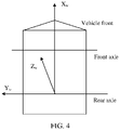
- FIG. 4 is a schematic diagram of the vehicle coordinate system provided in this application. In a top view of a vehicle body shown in FIG.
- a rear axle of the vehicle is used as a Y w axis
- a point at which the rear axle of the vehicle and a center line of an axle of the vehicle intersect is used as an origin of coordinates
- the center line of the axle of the vehicle is used as an X w axis
- a driving direction of the vehicle is used as a positive direction of the X w axis
- a plane formed by X w , O w , and Y w is parallel to a horizontal plane
- a direction perpendicular to the plane formed by X w , O w , and Y w is used as a direction of a Z w axis
- an upward direction perpendicular to the plane formed by X w , O w , and Y w is a positive direction of the Z w axis.
- a location of the traffic light relative to the vehicle coordinate system can be determined based on the location information of the traffic light relative to the intelligent vehicle.
- FIG. 5 is a schematic diagram of a location relationship between the vehicle coordinate system and the traffic light provided in this application.
- the distance of the traffic light relative to the vehicle is a coordinate value x of the traffic light on the X w axis
- the height of the traffic light is a coordinate value z of the traffic light on the Z w axis
- the distance from the vehicle to the road edge is a coordinate value y1 of a right side (relative to the vehicle) of the traffic light on the Y w axis
- a difference between the length of the traffic light and the distance from the vehicle to the road edge is a coordinate value y2 of a left side (relative to the vehicle) of the traffic light on the Y w axis.
- coordinates of four vertices of a rectangular region including the traffic light in the vehicle coordinate system are respectively A (x, y1, z), B (x, y1, z+L), C (x, y2, z), and D (x, y2, z+L).
- the coordinates of the four coordinate points are coordinates of the traffic light in a three-dimensional coordinate system. Coordinates of the four coordinate points in the pixel coordinate system can be determined based on a conversion relationship between the vehicle coordinate system and the pixel coordinate system, that is, the location information of the traffic light in the image.
- the controller 110 controls driving of the intelligent vehicle based on the status of the traffic light.
- the controller 110 controls driving of the intelligent vehicle based on the status of the traffic light. For example, when the status of traffic light is the green light, the intelligent vehicle is controlled to drive at a current speed; or when the status of the traffic light is the amber light or the red light, the intelligent vehicle is controlled to gradually decelerate to stop.
- the controller 110 recognizes the status of the traffic light according to the method in S201 to S205, and controls driving of the intelligent vehicle based on the status of the traffic light
- the controller 110 does not detect the display apparatus in the image collected by the image collection device 120
- the controller generates a reply instruction and sends the reply instruction to the image collection device 120, and then the image collection device adjusts the collection parameters to values existing before the adjustment instruction is received.
- the controller 110 after the controller 110 recognizes the traffic light by using the method in S201, the controller 110 cannot obtain the on/off period of the display apparatus and the duration in which the display apparatus is on in one on/off period.
- the controller 110 uses a common on/off period of the display apparatus as an on/off period of a display apparatus for a currently recognized traffic light, and uses common duration in which the display apparatus is on in one on/off period as duration in which the current traffic light is on in one on/off period.
- a common on/off period of the display apparatus is 20 ms, and duration in which a light is on in one on/off period is 2 ms.
- an on/off period of a current traffic light is set to 20 ms, and duration in which the traffic light is on in one on/off period is 2 ms. Then, according to a same method in S202 for determining the second collection period, the quantity of second exposure times, the second exposure duration, and the second exposure interval duration, the controller 110 determines the collection parameters adjusted by the image collection device 120.
- the controller 110 after the controller 110 recognizes the traffic light by using the method in S201, the controller 110 cannot obtain the on/off period of the display apparatus and the duration in which the display apparatus is on in one on/off period.
- the controller 110 obtains a current first collection period of the image collection device 120. If the first collection period is less than or equal to a preset collection period, that is, a quantity of images collected by the image collection device 120 within a unit time is greater than or equal to a preset quantity, the controller 110 determines that the image collection device 120 keeps the first collection period unchanged.
- the controller 110 determines that the collection period of the image collection device 120 is reduced from the first collection period to the preset collection period.
- the preset collection period is an on/off period usually used by the display apparatus. For example, if the on/off period usually used by the display apparatus is 20 ms, a value of the preset collection period is 20 ms.
- the controller 110 uses, as duration in which a current traffic light is on in one on/off period at present, duration which is usually used by the display apparatus and in which the traffic light is on in one on/off period.
- the controller 110 determines a collection period obtained after the image collection device 120 adjusts the collection parameters, and the duration in which the display apparatus is on in one on/off period.
- the controller determines the collection parameters adjusted by the image collection device 120, where the first collection period that is less than or equal to a first collection period obtained when the collection period is preset, or the second collection period when the first collection period is greater than the preset collection period, is the second collection period T2 calculated in S202.
- the preset collection period can be obtained through calculation based on statistical information of historical data, or can be an empirical value.
- the collection period, the quantity of exposure times, the exposure duration, and the exposure interval duration in the adjustment instruction generated by the controller 110 are all preset fixed values.
- the collection period is 20 ms
- the quantity of exposure times is 5
- the exposure duration is 2.5 ms
- the exposure interval duration is 1.5 ms.
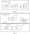
- FIG. 6 is a schematic diagram of a structure of an intelligent vehicle control apparatus provided in this application.
- the control apparatus is used in an intelligent vehicle that includes an image collection device and a positioning module.
- the image collection device is installed on the vehicle and is configured to collect an image of the vehicle in a driving direction.
- the control apparatus is connected to the image collection device, and is configured to receive an image collected by an image collection apparatus.
- the control apparatus 600 includes a processing unit 610, a sending unit 620, and an obtaining unit 630.
- the processing unit 610 is configured to calculate target values of collection parameters of the image collection device in the intelligent vehicle when recognizing a display apparatus for a signal identifier, where the collection parameters of the image collection device are used to indicate a collection period, a quantity of exposure times, exposure duration, and exposure interval duration that are of the image collection device to collect an image.
- the processing unit 610 can obtain, through the obtaining unit 630, an image collected by the image collection device, recognize the display apparatus for the signal identifier based on the image collected by the image collection device, and recognize the display apparatus for the signal identifier based on a distance between a location provided by the positioning module and the signal identifier.
- the processing unit 610 refer to related descriptions of recognizing the display apparatus by the controller 110 in S201.
- the processing unit 610 determines that the collection parameters of the image collection device need to be adjusted.
- the image collection device obtains, through the obtaining unit 630, an on/off period of the display apparatus and duration in which the signal identifier displayed on the display apparatus is on in one on/off period, where the on/off period includes duration in which the signal identifier is on and duration in which the signal identifier is off.
- the target values of the collection parameters of the image collection device such as the collection period, the quantity of exposure times, the exposure duration, and the exposure interval duration, are calculated based on the on/off period of the display apparatus and the duration in which the signal identifier displayed on the display apparatus is on in one on/off period.
- a method for calculating the collection parameters by the processing unit 610 refer to related descriptions of calculating the collection parameters by the controller 110 in S202. Details are not described herein again.
- the processing unit 610 generates an adjustment instruction based on the target values of the collection parameters.
- the adjustment instruction indicates the image collection device to adjust the collection parameters based on target values of collection parameters in the adjustment instruction.
- the sending unit 620 is configured to send the adjustment instruction to the image collection device.
- control apparatus 600 in this embodiment of this application can be implemented by using an application-specific integrated circuit (application-specific integrated circuit, ASIC) or a programmable logic device (programmable logic device, PLD).
- the PLD may be a complex programmable logic device (complex programmable logical device, CPLD), a field-programmable gate array (field-programmable gate array, FPGA), generic array logic (generic array logic, GAL), or any combination thereof.
- the control apparatus 600 and modules of the control apparatus 600 may also be software modules.
- the processing unit 610 is further configured to recognize the signal identifier based on an image obtained after the image collection device adjusts the collection parameters, and control driving of the intelligent vehicle based on the recognized signal identifier.
- a method for recognizing the signal identifier by the processing unit 610 based on the image collected by the image collection device refer to the method for recognizing the traffic light in S204. Details are not described herein again.
- the control apparatus 600 controls driving of the intelligent vehicle based on the status of the traffic light. For example, when the status of traffic light is a green light, the intelligent vehicle is controlled to drive at a current speed; or when the status of the traffic light is an amber light or a red light, the intelligent vehicle is controlled to gradually decelerate to stop.
- control apparatus 600 For operations performed by the control apparatus 600, refer to related operations performed by the controller 100 in the foregoing method embodiment, for example, recognizing the signal identifier, calculating the collection parameters, and recognizing the traffic light. Details are not described herein again.
- FIG. 7 is a schematic diagram of a structure of a computing device provided in this application.
- the computing device 700 includes at least a processor 710, a communication interface 720, and a memory 730.
- the processor 710, the communication interface 720, and the memory 730 are connected to each other by using a bus 740.
- the processor 710 is configured to execute instructions stored in the memory 730.
- the memory 730 stores program code, and the processor 710 can invoke the program code stored in the memory 720 to perform the following operations:
- a controller calculates target values of collection parameters of an image collection device in an intelligent vehicle, where the collection parameters of the image collection device are used to indicate a collection period, a quantity of exposure times, exposure duration, and exposure interval duration that are of the image collection device to collect an image;
- the processor 710 in this embodiment of this application may have a plurality of specific implementations.
- the processor 710 may be a central processing unit (central processing unit, CPU) or a graphics processing unit (graphics processing unit, GPU), and the processor 710 may also be a single-core processor or a multi-core processor.
- the processor 710 may be a combination of a CPU and a hardware chip.
- the hardware chip may be an application-specific integrated circuit (application-specific integrated circuit, ASIC), a programmable logic device (PLD), or a combination thereof.
- the PLD may be a complex programmable logic device (CPLD), a field-programmable gate array (FPGA), a generic array logic (GAL), or any combination thereof.
- the processor 710 may also be implemented by independently using a logic device with a built-in processing logic, for example, an FPGA or a digital signal processor (digital signal processor, DSP).
- the communication interface 720 may be a wired interface or a wireless interface, and is configured to communicate with another module or device.
- the wired interface may be an Ethernet interface, a controller area network (controller area network, CAN) interface, a local area network (local interconnect network, LIN) interface, or a FlexRay interface
- the wireless interface may be a cellular network interface, a wireless local area network interface, or the like.
- the communication interface 720 in this embodiment of this application may be specifically configured to receive image data sent by the image collection device, receive an on/off period sent by the display apparatus, and the like.
- the memory 730 may be a nonvolatile memory, for example, a read-only memory (read-only memory, ROM), a programmable read-only memory (programmable ROM, PROM), or an erasable programmable read-only memory (erasable PROM, EPROM), an electrically erasable programmable read-only memory (electrically EPROM, EEPROM) or a flash memory.
- the memory 730 may be a volatile memory.
- the volatile memory may be a random access memory (random access memory, RAM) and is used as an external cache.
- the memory 730 may also be configured to store instructions and data, so that the processor 710 invokes the instructions stored in the memory 730 to implement an operation performed by the processing unit 610, for example, the operation performed by the controller 110 in the foregoing method embodiment.
- the computing device 700 may include more or fewer components than those shown in FIG. 7 , or may have different component configurations.
- the bus 740 may be a CAN bus or another internal bus that implements interconnection between systems or devices in the vehicle.
- the bus 740 may be classified into an address bus, a data bus, a control bus, and the like. For ease of representation, only one bold line is used for representation in FIG. 7 , but this does not mean that there is only one bus or only one type of bus.
- the computing device 700 may further include an input/output interface 750.
- the input/output interface 750 is connected to an input/output device, and is configured to receive input information and output an operation result.
- the computing device 700 may correspond to the control apparatus 600 in the foregoing embodiment of this application, and may correspondingly perform corresponding operations in the method shown in FIG. 2 .
- operations and/or functions of the modules in the control apparatus 600 are separately used to implement corresponding procedures of the methods in FIG. 1 to FIG. 5 .
- details are not described herein again.
- An embodiment of this application further provides a non-transient computer storage medium.
- the computer storage medium stores instructions.
- the instructions When the instructions are run on a processor, the method steps in the foregoing method embodiments may be implemented.
- the method steps performed by the processor in the computer storage medium refer to specific operations in the foregoing method embodiments. Details are not described herein again.
- All or some of the foregoing embodiments may be implemented by using software, hardware, firmware, or any combination thereof.
- the software is used to implement the embodiments, all or some of the foregoing embodiments may be implemented in a form of a computer program product.
- the computer program product includes one or more computer instructions.
- the computer may be a general-purpose computer, a special-purpose computer, a computer network, or another programmable apparatus.
- the computer instructions may be stored in a computer-readable storage medium, or may be transmitted from one computer-readable storage medium to another computer-readable storage medium.
- the computer instructions may be transmitted from a website, a computer, a server, or a data center to another website, computer, server, or data center in a wired manner (for example, a coaxial cable, an optical fiber, or a digital subscriber line) or in a wireless manner (for example, infrared, wireless, or microwave).
- the computer-readable storage medium may be any usable medium that can be accessed by a computer, or a data storage device such as a server or a data center that includes one or more usable medium sets.
- the usable medium may be a magnetic medium (for example, a floppy disk, a hard disk drive, or a magnetic tape), an optical medium, or a semiconductor medium.
- the semiconductor medium may be a solid-state drive (solid-state drive, SSD).
Landscapes
- Engineering & Computer Science (AREA)
- Multimedia (AREA)
- Physics & Mathematics (AREA)
- General Physics & Mathematics (AREA)
- Theoretical Computer Science (AREA)
- Signal Processing (AREA)
- Health & Medical Sciences (AREA)
- General Health & Medical Sciences (AREA)
- Vascular Medicine (AREA)
- Traffic Control Systems (AREA)
Applications Claiming Priority (2)
| Application Number | Priority Date | Filing Date | Title |
|---|---|---|---|
| CN202010077052.4A CN113160590B (zh) | 2020-01-23 | 2020-01-23 | 智能汽车的控制方法、装置及相关设备 |
| PCT/CN2021/073282 WO2021147995A1 (fr) | 2020-01-23 | 2021-01-22 | Procédé et appareil de commande pour un véhicule intelligent, et dispositif associé |
Publications (2)
| Publication Number | Publication Date |
|---|---|
| EP4086874A1 true EP4086874A1 (fr) | 2022-11-09 |
| EP4086874A4 EP4086874A4 (fr) | 2023-05-31 |
Family
ID=76882153
Family Applications (1)
| Application Number | Title | Priority Date | Filing Date |
|---|---|---|---|
| EP21744507.1A Pending EP4086874A4 (fr) | 2020-01-23 | 2021-01-22 | Procédé et appareil de commande pour un véhicule intelligent, et dispositif associé |
Country Status (3)
| Country | Link |
|---|---|
| EP (1) | EP4086874A4 (fr) |
| CN (1) | CN113160590B (fr) |
| WO (1) | WO2021147995A1 (fr) |
Cited By (1)
| Publication number | Priority date | Publication date | Assignee | Title |
|---|---|---|---|---|
| US12286136B2 (en) | 2021-08-23 | 2025-04-29 | Honda Motor Co., Ltd. | Proceed-or-stop determination apparatus |
Families Citing this family (2)
| Publication number | Priority date | Publication date | Assignee | Title |
|---|---|---|---|---|
| CN115914097B (zh) * | 2021-08-11 | 2025-01-07 | 深圳智岩科技股份有限公司 | 控制发光设备的方法及相关设备 |
| CN113627362B (zh) * | 2021-08-13 | 2025-02-18 | 深圳市道通科技股份有限公司 | 指示信号识别方法、装置、设备以及计算机存储介质 |
Family Cites Families (14)
| Publication number | Priority date | Publication date | Assignee | Title |
|---|---|---|---|---|
| JP4937851B2 (ja) * | 2007-07-05 | 2012-05-23 | パナソニック株式会社 | 撮像装置 |
| JP2011193065A (ja) * | 2010-03-12 | 2011-09-29 | Hitachi Ltd | 撮像装置 |
| DE102010003039A1 (de) * | 2010-03-18 | 2011-09-22 | Basler Ag | Farbsättigungskorrektur |
| CN101977285B (zh) * | 2010-11-29 | 2015-09-02 | 杭州海康威视数字技术股份有限公司 | 摄像系统和摄像方法 |
| CN101977284B (zh) * | 2010-11-29 | 2012-07-18 | 杭州海康威视软件有限公司 | 摄像系统和摄像方法 |
| JP5680573B2 (ja) * | 2012-01-18 | 2015-03-04 | 富士重工業株式会社 | 車両の走行環境認識装置 |
| DE102012221159A1 (de) * | 2012-11-20 | 2014-05-22 | Robert Bosch Gmbh | Verfahren und Vorrichtung zum Erkennen von Wechselverkehrszeichen |
| JP6325000B2 (ja) * | 2013-12-25 | 2018-05-16 | 日立オートモティブシステムズ株式会社 | 車載画像認識装置 |
| JP2017011625A (ja) * | 2015-06-25 | 2017-01-12 | 三星ダイヤモンド工業株式会社 | 撮像装置 |
| CN105635597B (zh) * | 2015-12-21 | 2018-07-27 | 湖北工业大学 | 车载相机的自动曝光方法及系统 |
| US10380438B2 (en) * | 2017-03-06 | 2019-08-13 | Honda Motor Co., Ltd. | System and method for vehicle control based on red color and green color detection |
| US10453208B2 (en) * | 2017-05-19 | 2019-10-22 | Waymo Llc | Camera systems using filters and exposure times to detect flickering illuminated objects |
| JP2019036907A (ja) * | 2017-08-21 | 2019-03-07 | ソニーセミコンダクタソリューションズ株式会社 | 撮像装置及び機器 |
| CN111291620A (zh) * | 2020-01-14 | 2020-06-16 | 北京小马智行科技有限公司 | 识别光源的方法、装置和系统 |
-
2020
- 2020-01-23 CN CN202010077052.4A patent/CN113160590B/zh active Active
-
2021
- 2021-01-22 WO PCT/CN2021/073282 patent/WO2021147995A1/fr not_active Ceased
- 2021-01-22 EP EP21744507.1A patent/EP4086874A4/fr active Pending
Cited By (1)
| Publication number | Priority date | Publication date | Assignee | Title |
|---|---|---|---|---|
| US12286136B2 (en) | 2021-08-23 | 2025-04-29 | Honda Motor Co., Ltd. | Proceed-or-stop determination apparatus |
Also Published As
| Publication number | Publication date |
|---|---|
| CN113160590B (zh) | 2023-02-03 |
| WO2021147995A1 (fr) | 2021-07-29 |
| EP4086874A4 (fr) | 2023-05-31 |
| CN113160590A (zh) | 2021-07-23 |
Similar Documents
| Publication | Publication Date | Title |
|---|---|---|
| US12340593B2 (en) | Vehicle drivable area detection method, system, and autonomous vehicle using the system | |
| US11468581B2 (en) | Distance measurement method, intelligent control method, electronic device, and storage medium | |
| US11670083B2 (en) | Vision based light detection and ranging system using dynamic vision sensor | |
| US20210311167A1 (en) | Multisensor Data Fusion Method and Apparatus | |
| US8908924B2 (en) | Exterior environment recognition device and exterior environment recognition method | |
| JP7095640B2 (ja) | 物体検出装置 | |
| CN106919908B (zh) | 障碍物识别方法及装置、计算机设备及可读介质 | |
| EP4086874A1 (fr) | Procédé et appareil de commande pour un véhicule intelligent, et dispositif associé | |
| JP2019008460A (ja) | 物体検出装置、物体検出方法およびプログラム | |
| JP2019096072A (ja) | 物体検出装置、物体検出方法およびプログラム | |
| CN112580571A (zh) | 车辆行驶的控制方法、装置及电子设备 | |
| US11624831B2 (en) | Obstacle detection method and apparatus and storage medium | |
| GB2553650A (en) | Heads up display for observing vehicle perception activity | |
| EP4524674A1 (fr) | Procédé et appareil d'évitement d'obstacle basés sur la vision binoculaire, robot et support | |
| WO2022188292A1 (fr) | Procédé et système de détection de cible, et procédé de commande, dispositifs, et support de stockage | |
| EP3637758B1 (fr) | Dispositif de traitement d'images | |
| WO2023029468A1 (fr) | Invite de conduite de véhicule | |
| WO2021215116A1 (fr) | Dispositif de reconnaissance d'image et procédé de reconnaissance d'image | |
| CN119026074A (zh) | 一种多传感器融合感知方法、装置、终端及存储介质 | |
| CN118636793A (zh) | 电子后视镜的调节方法、装置、电子设备及可读存储介质 | |
| US20250076027A1 (en) | Obstacle ranging method and device, vehicle and medium | |
| JP7797981B2 (ja) | 情報処理方法 | |
| US20250078527A1 (en) | Traffic sign detection method, storage medium, and electronic device | |
| TWI890163B (zh) | 防撞預警方法、車載裝置及存儲介質 | |
| US11688176B2 (en) | Devices and methods for calibrating vehicle cameras |
Legal Events
| Date | Code | Title | Description |
|---|---|---|---|
| STAA | Information on the status of an ep patent application or granted ep patent |
Free format text: STATUS: THE INTERNATIONAL PUBLICATION HAS BEEN MADE |
|
| PUAI | Public reference made under article 153(3) epc to a published international application that has entered the european phase |
Free format text: ORIGINAL CODE: 0009012 |
|
| STAA | Information on the status of an ep patent application or granted ep patent |
Free format text: STATUS: REQUEST FOR EXAMINATION WAS MADE |
|
| 17P | Request for examination filed |
Effective date: 20220803 |
|
| AK | Designated contracting states |
Kind code of ref document: A1 Designated state(s): AL AT BE BG CH CY CZ DE DK EE ES FI FR GB GR HR HU IE IS IT LI LT LU LV MC MK MT NL NO PL PT RO RS SE SI SK SM TR |
|
| REG | Reference to a national code |
Ref country code: DE Ref legal event code: R079 Free format text: PREVIOUS MAIN CLASS: G08G0001090000 Ipc: G06V0020580000 |
|
| DAV | Request for validation of the european patent (deleted) | ||
| DAX | Request for extension of the european patent (deleted) | ||
| A4 | Supplementary search report drawn up and despatched |
Effective date: 20230428 |
|
| RIC1 | Information provided on ipc code assigned before grant |
Ipc: H04N 23/73 20230101ALI20230421BHEP Ipc: G08G 1/0962 20060101ALI20230421BHEP Ipc: G06V 10/147 20220101ALI20230421BHEP Ipc: G06V 20/58 20220101AFI20230421BHEP |
|
| RAP1 | Party data changed (applicant data changed or rights of an application transferred) |
Owner name: SHENZHEN YINWANG INTELLIGENTTECHNOLOGIES CO., LTD. |
|
| STAA | Information on the status of an ep patent application or granted ep patent |
Free format text: STATUS: EXAMINATION IS IN PROGRESS |
|
| 17Q | First examination report despatched |
Effective date: 20250425 |