EP4087031B1 - Batterie secondaire ayant une couche conductrice formée sur la surface interne d'un boîtier de batterie - Google Patents
Batterie secondaire ayant une couche conductrice formée sur la surface interne d'un boîtier de batterie Download PDFInfo
- Publication number
- EP4087031B1 EP4087031B1 EP21886609.3A EP21886609A EP4087031B1 EP 4087031 B1 EP4087031 B1 EP 4087031B1 EP 21886609 A EP21886609 A EP 21886609A EP 4087031 B1 EP4087031 B1 EP 4087031B1
- Authority
- EP
- European Patent Office
- Prior art keywords
- secondary battery
- case
- electrode assembly
- conductive
- cap
- Prior art date
- Legal status (The legal status is an assumption and is not a legal conclusion. Google has not performed a legal analysis and makes no representation as to the accuracy of the status listed.)
- Active
Links
Images


Classifications
-
- H—ELECTRICITY
- H01—ELECTRIC ELEMENTS
- H01M—PROCESSES OR MEANS, e.g. BATTERIES, FOR THE DIRECT CONVERSION OF CHEMICAL ENERGY INTO ELECTRICAL ENERGY
- H01M50/00—Constructional details or processes of manufacture of the non-active parts of electrochemical cells other than fuel cells, e.g. hybrid cells
- H01M50/10—Primary casings; Jackets or wrappings
- H01M50/116—Primary casings; Jackets or wrappings characterised by the material
- H01M50/124—Primary casings; Jackets or wrappings characterised by the material having a layered structure
- H01M50/1243—Primary casings; Jackets or wrappings characterised by the material having a layered structure characterised by the internal coating on the casing
-
- H—ELECTRICITY
- H01—ELECTRIC ELEMENTS
- H01M—PROCESSES OR MEANS, e.g. BATTERIES, FOR THE DIRECT CONVERSION OF CHEMICAL ENERGY INTO ELECTRICAL ENERGY
- H01M10/00—Secondary cells; Manufacture thereof
- H01M10/04—Construction or manufacture in general
- H01M10/0422—Cells or battery with cylindrical casing
-
- H—ELECTRICITY
- H01—ELECTRIC ELEMENTS
- H01M—PROCESSES OR MEANS, e.g. BATTERIES, FOR THE DIRECT CONVERSION OF CHEMICAL ENERGY INTO ELECTRICAL ENERGY
- H01M10/00—Secondary cells; Manufacture thereof
- H01M10/04—Construction or manufacture in general
- H01M10/0422—Cells or battery with cylindrical casing
- H01M10/0427—Button cells
-
- H—ELECTRICITY
- H01—ELECTRIC ELEMENTS
- H01M—PROCESSES OR MEANS, e.g. BATTERIES, FOR THE DIRECT CONVERSION OF CHEMICAL ENERGY INTO ELECTRICAL ENERGY
- H01M10/00—Secondary cells; Manufacture thereof
- H01M10/04—Construction or manufacture in general
- H01M10/0431—Cells with wound or folded electrodes
-
- H—ELECTRICITY
- H01—ELECTRIC ELEMENTS
- H01M—PROCESSES OR MEANS, e.g. BATTERIES, FOR THE DIRECT CONVERSION OF CHEMICAL ENERGY INTO ELECTRICAL ENERGY
- H01M10/00—Secondary cells; Manufacture thereof
- H01M10/04—Construction or manufacture in general
- H01M10/0468—Compression means for stacks of electrodes and separators
-
- H—ELECTRICITY
- H01—ELECTRIC ELEMENTS
- H01M—PROCESSES OR MEANS, e.g. BATTERIES, FOR THE DIRECT CONVERSION OF CHEMICAL ENERGY INTO ELECTRICAL ENERGY
- H01M50/00—Constructional details or processes of manufacture of the non-active parts of electrochemical cells other than fuel cells, e.g. hybrid cells
- H01M50/10—Primary casings; Jackets or wrappings
- H01M50/102—Primary casings; Jackets or wrappings characterised by their shape or physical structure
- H01M50/103—Primary casings; Jackets or wrappings characterised by their shape or physical structure prismatic or rectangular
-
- H—ELECTRICITY
- H01—ELECTRIC ELEMENTS
- H01M—PROCESSES OR MEANS, e.g. BATTERIES, FOR THE DIRECT CONVERSION OF CHEMICAL ENERGY INTO ELECTRICAL ENERGY
- H01M50/00—Constructional details or processes of manufacture of the non-active parts of electrochemical cells other than fuel cells, e.g. hybrid cells
- H01M50/10—Primary casings; Jackets or wrappings
- H01M50/102—Primary casings; Jackets or wrappings characterised by their shape or physical structure
- H01M50/107—Primary casings; Jackets or wrappings characterised by their shape or physical structure having curved cross-section, e.g. round or elliptic
-
- H—ELECTRICITY
- H01—ELECTRIC ELEMENTS
- H01M—PROCESSES OR MEANS, e.g. BATTERIES, FOR THE DIRECT CONVERSION OF CHEMICAL ENERGY INTO ELECTRICAL ENERGY
- H01M50/00—Constructional details or processes of manufacture of the non-active parts of electrochemical cells other than fuel cells, e.g. hybrid cells
- H01M50/10—Primary casings; Jackets or wrappings
- H01M50/102—Primary casings; Jackets or wrappings characterised by their shape or physical structure
- H01M50/109—Primary casings; Jackets or wrappings characterised by their shape or physical structure of button or coin shape
-
- H—ELECTRICITY
- H01—ELECTRIC ELEMENTS
- H01M—PROCESSES OR MEANS, e.g. BATTERIES, FOR THE DIRECT CONVERSION OF CHEMICAL ENERGY INTO ELECTRICAL ENERGY
- H01M50/00—Constructional details or processes of manufacture of the non-active parts of electrochemical cells other than fuel cells, e.g. hybrid cells
- H01M50/10—Primary casings; Jackets or wrappings
- H01M50/116—Primary casings; Jackets or wrappings characterised by the material
- H01M50/117—Inorganic material
- H01M50/119—Metals
-
- H—ELECTRICITY
- H01—ELECTRIC ELEMENTS
- H01M—PROCESSES OR MEANS, e.g. BATTERIES, FOR THE DIRECT CONVERSION OF CHEMICAL ENERGY INTO ELECTRICAL ENERGY
- H01M50/00—Constructional details or processes of manufacture of the non-active parts of electrochemical cells other than fuel cells, e.g. hybrid cells
- H01M50/10—Primary casings; Jackets or wrappings
- H01M50/116—Primary casings; Jackets or wrappings characterised by the material
- H01M50/121—Organic material
-
- H—ELECTRICITY
- H01—ELECTRIC ELEMENTS
- H01M—PROCESSES OR MEANS, e.g. BATTERIES, FOR THE DIRECT CONVERSION OF CHEMICAL ENERGY INTO ELECTRICAL ENERGY
- H01M50/00—Constructional details or processes of manufacture of the non-active parts of electrochemical cells other than fuel cells, e.g. hybrid cells
- H01M50/10—Primary casings; Jackets or wrappings
- H01M50/147—Lids or covers
- H01M50/166—Lids or covers characterised by the methods of assembling casings with lids
-
- H—ELECTRICITY
- H01—ELECTRIC ELEMENTS
- H01M—PROCESSES OR MEANS, e.g. BATTERIES, FOR THE DIRECT CONVERSION OF CHEMICAL ENERGY INTO ELECTRICAL ENERGY
- H01M50/00—Constructional details or processes of manufacture of the non-active parts of electrochemical cells other than fuel cells, e.g. hybrid cells
- H01M50/10—Primary casings; Jackets or wrappings
- H01M50/183—Sealing members
- H01M50/184—Sealing members characterised by their shape or structure
-
- H—ELECTRICITY
- H01—ELECTRIC ELEMENTS
- H01M—PROCESSES OR MEANS, e.g. BATTERIES, FOR THE DIRECT CONVERSION OF CHEMICAL ENERGY INTO ELECTRICAL ENERGY
- H01M50/00—Constructional details or processes of manufacture of the non-active parts of electrochemical cells other than fuel cells, e.g. hybrid cells
- H01M50/10—Primary casings; Jackets or wrappings
- H01M50/183—Sealing members
- H01M50/186—Sealing members characterised by the disposition of the sealing members
-
- H—ELECTRICITY
- H01—ELECTRIC ELEMENTS
- H01M—PROCESSES OR MEANS, e.g. BATTERIES, FOR THE DIRECT CONVERSION OF CHEMICAL ENERGY INTO ELECTRICAL ENERGY
- H01M50/00—Constructional details or processes of manufacture of the non-active parts of electrochemical cells other than fuel cells, e.g. hybrid cells
- H01M50/40—Separators; Membranes; Diaphragms; Spacing elements inside cells
- H01M50/409—Separators, membranes or diaphragms characterised by the material
- H01M50/411—Organic material
- H01M50/414—Synthetic resins, e.g. thermoplastics or thermosetting resins
- H01M50/417—Polyolefins
-
- H—ELECTRICITY
- H01—ELECTRIC ELEMENTS
- H01M—PROCESSES OR MEANS, e.g. BATTERIES, FOR THE DIRECT CONVERSION OF CHEMICAL ENERGY INTO ELECTRICAL ENERGY
- H01M50/00—Constructional details or processes of manufacture of the non-active parts of electrochemical cells other than fuel cells, e.g. hybrid cells
- H01M50/40—Separators; Membranes; Diaphragms; Spacing elements inside cells
- H01M50/471—Spacing elements inside cells other than separators, membranes or diaphragms; Manufacturing processes thereof
- H01M50/474—Spacing elements inside cells other than separators, membranes or diaphragms; Manufacturing processes thereof characterised by their position inside the cells
-
- H—ELECTRICITY
- H01—ELECTRIC ELEMENTS
- H01M—PROCESSES OR MEANS, e.g. BATTERIES, FOR THE DIRECT CONVERSION OF CHEMICAL ENERGY INTO ELECTRICAL ENERGY
- H01M50/00—Constructional details or processes of manufacture of the non-active parts of electrochemical cells other than fuel cells, e.g. hybrid cells
- H01M50/40—Separators; Membranes; Diaphragms; Spacing elements inside cells
- H01M50/471—Spacing elements inside cells other than separators, membranes or diaphragms; Manufacturing processes thereof
- H01M50/48—Spacing elements inside cells other than separators, membranes or diaphragms; Manufacturing processes thereof characterised by the material
- H01M50/483—Inorganic material
-
- H—ELECTRICITY
- H01—ELECTRIC ELEMENTS
- H01M—PROCESSES OR MEANS, e.g. BATTERIES, FOR THE DIRECT CONVERSION OF CHEMICAL ENERGY INTO ELECTRICAL ENERGY
- H01M50/00—Constructional details or processes of manufacture of the non-active parts of electrochemical cells other than fuel cells, e.g. hybrid cells
- H01M50/50—Current conducting connections for cells or batteries
- H01M50/572—Means for preventing undesired use or discharge
- H01M50/574—Devices or arrangements for the interruption of current
- H01M50/578—Devices or arrangements for the interruption of current in response to pressure
-
- H—ELECTRICITY
- H01—ELECTRIC ELEMENTS
- H01M—PROCESSES OR MEANS, e.g. BATTERIES, FOR THE DIRECT CONVERSION OF CHEMICAL ENERGY INTO ELECTRICAL ENERGY
- H01M4/00—Electrodes
- H01M4/02—Electrodes composed of, or comprising, active material
- H01M2004/026—Electrodes composed of, or comprising, active material characterised by the polarity
- H01M2004/027—Negative electrodes
-
- H—ELECTRICITY
- H01—ELECTRIC ELEMENTS
- H01M—PROCESSES OR MEANS, e.g. BATTERIES, FOR THE DIRECT CONVERSION OF CHEMICAL ENERGY INTO ELECTRICAL ENERGY
- H01M4/00—Electrodes
- H01M4/02—Electrodes composed of, or comprising, active material
- H01M2004/026—Electrodes composed of, or comprising, active material characterised by the polarity
- H01M2004/028—Positive electrodes
-
- H—ELECTRICITY
- H01—ELECTRIC ELEMENTS
- H01M—PROCESSES OR MEANS, e.g. BATTERIES, FOR THE DIRECT CONVERSION OF CHEMICAL ENERGY INTO ELECTRICAL ENERGY
- H01M50/00—Constructional details or processes of manufacture of the non-active parts of electrochemical cells other than fuel cells, e.g. hybrid cells
- H01M50/30—Arrangements for facilitating escape of gases
- H01M50/342—Non-re-sealable arrangements
-
- Y—GENERAL TAGGING OF NEW TECHNOLOGICAL DEVELOPMENTS; GENERAL TAGGING OF CROSS-SECTIONAL TECHNOLOGIES SPANNING OVER SEVERAL SECTIONS OF THE IPC; TECHNICAL SUBJECTS COVERED BY FORMER USPC CROSS-REFERENCE ART COLLECTIONS [XRACs] AND DIGESTS
- Y02—TECHNOLOGIES OR APPLICATIONS FOR MITIGATION OR ADAPTATION AGAINST CLIMATE CHANGE
- Y02E—REDUCTION OF GREENHOUSE GAS [GHG] EMISSIONS, RELATED TO ENERGY GENERATION, TRANSMISSION OR DISTRIBUTION
- Y02E60/00—Enabling technologies; Technologies with a potential or indirect contribution to GHG emissions mitigation
- Y02E60/10—Energy storage using batteries
-
- Y—GENERAL TAGGING OF NEW TECHNOLOGICAL DEVELOPMENTS; GENERAL TAGGING OF CROSS-SECTIONAL TECHNOLOGIES SPANNING OVER SEVERAL SECTIONS OF THE IPC; TECHNICAL SUBJECTS COVERED BY FORMER USPC CROSS-REFERENCE ART COLLECTIONS [XRACs] AND DIGESTS
- Y02—TECHNOLOGIES OR APPLICATIONS FOR MITIGATION OR ADAPTATION AGAINST CLIMATE CHANGE
- Y02P—CLIMATE CHANGE MITIGATION TECHNOLOGIES IN THE PRODUCTION OR PROCESSING OF GOODS
- Y02P70/00—Climate change mitigation technologies in the production process for final industrial or consumer products
- Y02P70/50—Manufacturing or production processes characterised by the final manufactured product
Definitions
- the present disclosure relates to a secondary battery having a conductive layer formed on the inner surface of a battery case.
- a secondary battery is a representative example of an electrochemical device that utilizes such electrochemical energy, and the range of use thereof tends to be gradually expanding.
- the secondary battery has a structure in which an electrode assembly comprising a positive electrode, a negative electrode, and a porous separator is built into in a battery case in a state of being impregnated with a non-aqueous electrolyte.
- a secondary battery may be generally classified as a cylindrical secondary battery or a prismatic secondary battery in which a stacked/folded type, or wound type electrode assembly is housed in a case made of metal as a battery case, a pouch type secondary battery in which a stacked type or stacked/folding type electrode assembly is built into a pouch type battery case made of an aluminum laminate sheet, and a coin-type secondary battery in which a coin-type electrode assembly is housed in an upper case and a lower case made of metal.
- US 2006/127758 A1 discloses a coin-type alkaline cell with a can made from nickel or stainless steel which undergoes a surface treatment with an electrically conductive polymer, polyaniline and tin.
- the cell also comprises a ring gasket which seals the first and the second case.
- CN 107658477 B discloses an alkaline zinc-manganese dry battery having a cylindrical shape composed of a steel case with a sealing ring and a current collector.
- the steel case has a conductive coating on its inner wall comprising of graphene.
- the conductive coating also contains a binder.
- WO 2013/153693 A1 discloses that maintaining electrodes under a compressive force improves the life of a battery.
- US 2019/109303 A1 discloses a safety mechanism comprising of a disk plate as a safety valve and a shut-off disk, which releases and shuts off the connection in a battery.
- WO 2019/171761 A1 discloses a positive electrode including a positive electrode current collector, a positive electrode mixed material layer that is formed on at least one surface of the positive electrode current collector, and a protective layer which includes an insulating inorganic compound and a conductive material, and is interposed between the positive electrode current collector and the positive electrode mixed material layer.
- the present disclosure has been made to solve the above-mentioned problems and other technical problems that have yet to be resolved.
- an object of the present disclosure is to provide a secondary battery that can effectively suppress the corrosion of the secondary battery case due to contact with the electrolyte.
- a secondary battery configured such that an electrode assembly including a positive electrode, a separator, and a negative electrode is housed in a battery case together with an electrolyte solution, wherein the battery case is made of metal, and a conductive layer consisting of a a conductive epoxy layer is formed on a part or the whole of the inner surface of the battery case coming into contact with the electrolyte solution.
- the secondary battery further comprises a spring and a spacer that fill an inner space excluding the electrode assembly in the inside of the first case and the second case,
- the secondary battery may further comprise a gasket for sealing the first case and the second case.
- the secondary battery is a cylindrical secondary battery
- a gasket is mounted on the upper part of the beading part of the cylindrical can,
- the electrode assembly is a jelly-roll type or stack/folding type electrode assembly
- the electrode assembly comprises a positive electrode tab and a negative electrode tab drawn out from the electrode assembly, wherein the positive tab and the negative tab are respectively connected to the cap terminals, and a conductive epoxy layer is formed on the inside surface of the secondary battery, in at least one member selected from the group consisting of the positive electrode tab and the negative electrode tab.
- the metal may be made of any one selected from the group consisting of aluminum, nickel, stainless steel (SUS), copper, iron, bronze, and brass.
- the secondary battery may further comprise a hollow center pin inserted into the center of the electrode assembly.
- the conductive layer may be formed to a thickness of 0.01 ⁇ m to 100 ⁇ m.
- the conductive epoxy layer may comprise at least one conductive filler selected from the group consisting of gold, platinum, silver, copper, or nickel metal powder, carbon or carbon fiber, graphite, and composite powder, and an epoxy polymer.
- a secondary battery configured such that an electrode assembly including a positive electrode, a separator, and a negative electrode is housed in a battery case together with an electrolyte solution, wherein the battery case is made of metal, and a conductive layer p consisting of a conductive epoxy layer is formed on a part or the whole of the inner surface of the battery case coming into contact with the electrolyte solution.
- the position where the conductive layer is formed may differ depending on the type of secondary battery.
- the conductive layer is formed on a surface coming into contact with an electrolyte solution, and more specifically, the conductive layer may be formed at a position at which it should have conductivity while coming into contact with the electrolyte solution.
- the secondary battery may be a coin-type secondary battery
- a conductive layer can be formed on a surface where the first case, the second case, the spring, and the spacer come into contact with the electrolyte, thereby preventing corrosion due to the electrolyte solution while having conductivity.
- the gasket is generally made of an insulating material and thus, the conductive layer need not be formed. However, the conductive layer may also be formed on a surface of the gasket, and such a structure is not excluded.
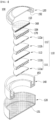
- a perspective view of a coin-type secondary battery having such a conductive layer formed therein is shown in Fig. 1
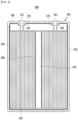
- a schematic diagram of the cross section is shown in Fig. 2 .
- the electrode assembly 110 includes a positive electrode 111, a negative electrode 112, and a separator 113 interposed between the positive electrode 111 and the negative electrode 112, wherein the positive electrode 111, the negative electrode 112 and the separator 113 have a coin-type structure.
- the coin-type secondary battery 100 may further include a gasket 140 for sealing the first case 120 and the second case 130.
- the conductive layers 151 , 152, 153 and 154 preferably include a material having conductivity, considering that the cases, spring and spacer of the coin-type secondary battery are made of metal, and these themselves serve as electrode terminals.
- the conductive layers 151 , 152 , 153 and 154 are formed wholly on the inner surface of the case, ensuring conductivity as much as corrosion is prevented is a very important issue. Even if the corrosion is prevented, the performance as a secondary battery will be eventually deteriorated if the conductivity is not sufficiently secured, and thus there is no choice but to lose the meaning of the invention.
- the secondary battery is a cylindrical secondary battery
- the electrode assembly is a jelly-roll type or stack/folding type electrode assembly
- a gasket is mounted on the upper part of the beading part of the cylindrical can,
- the bottom part of the cylindrical can and the components of the cap assembly are made of metal, and the degree of corrosion is severe depending on what kind of material is used as the electrolyte solution, the lifespan characteristics are deteriorated, or it will be unusable any more or the safety may be threatened.
- the components necessarily require conductivity.
- a conductive layer can be formed on a surface where the components come into contact with the electrolyte solution, thereby preventing corrosion due to the electrolyte solution while having conductivity.
- the housing part, the beading part, and the gasket excluding the bottom surface of the cylindrical can do not necessarily require conductivity as described above, and thus the conductive layer does not need to be formed.
- a conductive layer may also be formed on the surfaces of these components, and such a structure is not excluded.
- the secondary battery 200 is structured such that an electrode assembly 120 including a positive electrode, a separator, and a negative electrode is housed together with an electrolyte solution in a cylindrical can 210 including a housing part 211 and a beading part 212 as a battery case, wherein a cap assembly 230 including the upper end cap 231 is located at the opened upper end part of the cylindrical can 210 and seals the cylindrical can 210.
- the electrode assembly 220 may be a jelly-roll type or a stack/folding type electrode assembly, without being limited thereto.
- the jelly-roll type electrode assembly is manufactured by interposing a sheet-type separator between a sheet-type positive electrode and a sheet-type negative electrode and winding it.
- the secondary battery 200 includes a gasket 240 mounted on the upper end part of the beading part 212 of the cylindrical can 210, and is formed in a structure in which the cap assembly 230 includes an upper end cap 231, a current interruption safety device (PTC device, 232) stacked under the upper end cap 231 and a safety vent 233 for internal pressure drop, and a current interruption device (CID) 234 formed at the lower end of the safety vent 233.
- PTC device current interruption safety device
- CID current interruption device
- the positive electrode tab 221 and the negative electrode tab 222 are drawn out from the electrode assembly 220, the positive electrode tab 221 is connected to the cap assembly 230, and the negative electrode tab 222 is connected to a bottom surface 213 spaced apart from a housing part 211 of the cylindrical can 230.
- the current interruption safety device 232, the safety vent 233, and the current interruption device 234 all are preferably structures through which current flows, which are formed in order to ensure the safety of the secondary battery.
- the current interruption safety device 232, the safety vent 233, the current interruption device 234, as well as the upper end cap 231 serving as a positive electrode terminal, the bottom surface 213 of the cylindrical can 210 serving as a negative electrode terminal, and the positive electrode tab 221 and the negative electrode tab 222 preferably have conductivity. Therefore, a conductive layer 170 may be formed on the inside surface of the secondary battery 100 in order to prevent corrosion due to leakage of the electrolyte solution while maintaining conductivity, in which the secondary battery 100 includes the upper end cap 131, the bottom surface 113 of the cylindrical can, the current interruption safety device 132, the safety vent 133, the current interruption device 134, the positive electrode tab 121, and the negative electrode tab 122.
- the conductive layer 170 may be formed wholly on the surface of the above members exposed inside the secondary battery, but may be formed only on a surface toward the electrode assembly in each member.
- a conductive layer for corrosion prevention may be formed on the housing part 211, the beading part 212, and the gasket 140 excluding the bottom surface 213 of the cylindrical can 210, without being limited thereto, or the above components do not necessarily require conductivity, and thus other anti-corrosion layers 160 may be formed.
- the secondary battery 200 may further include a hollow center pin 250 inserted into the center of the jelly-roll type electrode assembly 220.
- the center pin 250 may also be made of any one selected from the group consisting of metal, specifically aluminum, nickel, stainless steel (SUS), copper, iron, bronze, and brass, which thus causes corrosion to the electrolyte.
- metal specifically aluminum, nickel, stainless steel (SUS), copper, iron, bronze, and brass, which thus causes corrosion to the electrolyte.
- SUS stainless steel
- copper iron, bronze, and brass
- the conductivity is not necessarily required.
- a conductive layer may be formed, other anti-corrosion layers 280 may be additionally formed, and more specifically, the anti-corrosion layer 280 may be formed up to the hollow inner surface.
- the conductive layer 270 may be formed at a portion that is likely to come into contact with the electrolyte solution, whereby the conductivity may not be lowered while effectively preventing corrosion due to contact with the electrolyte solution, which is thus more preferable.
- the secondary battery is a prismatic secondary battery
- the electrode assembly comprises a positive electrode tab and a negative electrode tab drawn out from the electrode assembly, wherein the positive tab and the negative tab are respectively connected to the cap terminals, and a conductive epoxy layer is formed on the inside surface of the secondary battery, in at least one member selected from the group consisting of the positive electrode tab and the negative electrode tab.
- the inner surface of the cap terminals of the top cap, the positive electrode tab, and the negative electrode tab are made of metal, and the degree of corrosion is severe depending on what kind of material is used as the electrolyte solution, the lifespan characteristics are deteriorated, or it will be unusable any more or the safety may be threatened.
- these components necessarily require conductivity.
- a conductive layer can be formed on a surface where the components come into contact with the electrolyte solution, thereby preventing corrosion due to the electrolyte solution while having conductivity.
- a perspective view of a prismatic secondary battery in which such a conductive layer is formed is shown in Fig. 4 below.
- the secondary battery 300 comprises a rectangular can body 310 that is opened in its upper end and houses the electrode assembly 320 and the electrolyte solution together, and a top cap 330 including cap terminals 331 that are coupled and sealed to the upper end part of the can body 310 and are connected to the electrode terminals 321 and 322 of the electrode assembly 320.
- the electrode assembly 320 is the same as those described for the cylindrical secondary battery.
- the electrode assembly 320 includes a positive electrode tab 321 and a negative electrode tab 322 drawn upward from the electrode assembly 320, and the positive electrode tab 321 and the negative electrode tab 322 are respectively connected to the can terminals 331.
- a conductive layer 270 made of one selected from the group consisting of a conductive carbon layer, a conductive polymer layer, and a conductive epoxy layer are formed on the inside surface of the secondary battery 300.
- a conductive layer for corrosion prevention may be formed on the portion excluding the cap terminals 331 of the prismatic can body 310 and the top cap 330, without being limited thereto, or the components do not necessarily require conductivity and thus, other anti-corrosion layers 250 and 260 may be formed.
- the secondary battery 300 may further include a hollow center pin 340 inserted into the center of the jelly-roll type electrode assembly 320.
- the center pin 340 may also made of metal, specifically any one selected from the group consisting of aluminum, nickel, stainless steel (SUS), copper, iron, bronze, and brass, which thus causes corrosion to the electrolyte solution.
- SUS stainless steel
- the conductivity is not necessarily required.
- the conductive layer may have a thickness of 0.01 ⁇ m to 100 ⁇ m, specifically 0.5 ⁇ m to 30 ⁇ m, and more specifically, 1 ⁇ m to 10 ⁇ m.
- the conductive layer is too thin outside the above range, it cannot exhibit a sufficient anti-corrosion effect, and if the conductive layer is too thick, the conductivity may be lowered or the bulk energy density may be lowered, which is thus not preferable.
- the metals constituting the above components may be made of any one selected from the group consisting of aluminum, nickel, stainless steel (SUS), copper, iron, bronze, and brass, and specifically, it may be made of aluminum or stainless steel (SUS), and more specifically, it may be made of stainless steel (SUS).
- a coin-type secondary battery was manufactured in the same manner in Example 1, except that in Example 1, the conductive carbon layer precursor solution prepared in Preparation Example 2 was coated (spray coated) onto the surface where the first case, the second case, the spring, and the spacer as a coin-type battery case could come into contact with the electrolyte solution.
- a coin-type secondary battery was manufactured in the same manner in Example 1, except that in Example 1, the conductive carbon layer precursor solution prepared in Preparation Example 3 was coated (spray coated) onto the surface where the first case, the second case, the spring, and the spacer as a coin-type battery case could come into contact with the electrolyte solution.
- a coin-type secondary battery was manufactured in the same manner in Example 1, except that in Example 1, any coating treatment was not performed onto the surface where the first case, the second case, the spring, and the spacer as a coin-type battery case could come into contact with the electrolyte solution.
- the coin cell batteries manufactured in Examples 1 and 4 and 5 were rate-evaluated under the following conditions.
- the conductive carbon layer precursor solution prepared in Preparation Example 1 was coated (spray coated) onto the housing part of the cylindrical battery case, the beading part and the upper end cap.
- a positive electrode mixture having a composition of 95 wt.% of positive active material (LiNi 0.6 Co 0.2 Mn 0.2 O 2 ), 2.5 wt.% of Super-P (conductive material), and 2.5 wt.% of PVDF (binder) was added to NMP (N-methyl-2- pyrrolidone) as a solvent to prepare a positive electrode slurry, and then the slurry was coated (100 ⁇ m) onto an aluminum current collector substrate to prepare a coin-type positive electrode.
- positive active material LiNi 0.6 Co 0.2 Mn 0.2 O 2
- Super-P conductive material
- PVDF binder
- a negative electrode mixture having a composition of 95 wt.% of artificial graphite, 2.5 wt.% of Super-P (conductive material), and 2.5 wt.% of PVDF (binder) was added to NMP (N-methyl-2- pyrrolidone) as a solvent to prepare a negative electrode slurry, and then the slurry was coated (100 ⁇ m) onto a copper current collector substrate to prepare a coin-type negative electrode.
- a polyethylene-based separator was interposed between the prepared positive electrode and negative electrode to prepare an electrode assembly, and the electrode assembly was incorporated in the cylindrical battery case as shown in Fig. 1 , and a solution of ethylene carbonate (EC) and dimethyl carbonate (DMC) in a volume ratio of 1:1 in which 1 M LiFSI was dissolved was injected as an electrolyte, and then sealed with a gasket to manufacture a cylindrical secondary battery.
- EC ethylene carbonate
- DMC dimethyl carbonate
- a cylindrical secondary battery was manufactured in the same manner in Example 6, except that in Example 1, the conductive polymer layer precursor solution prepared in Preparation Example 4 was coated onto the housing part of the cylindrical battery case, the beading part and the upper end cap.
- a cylindrical secondary battery was manufactured in the same manner in Example 6, except that in Example 1, the conductive epoxy layer precursor solution prepared in Preparation Example 5 was coated onto the housing part of the cylindrical battery case, the beading part and the upper end cap.
- a cylindrical secondary battery was manufactured in the same manner in Example 6, except that in Example 1, the conductive carbon layer precursor solution prepared in Preparation Example 3 was coated onto the housing part of the cylindrical battery case, the beading part and the upper end cap.
- a cylindrical secondary battery was manufactured in the same manner in Example 6, except that in Example 1, the binder solution prepared in Preparation Example 6 was coated onto the housing part of the cylindrical battery case and the beading part.
- the binder coating was formed only on the housing part and the beading part.
- the cylindrical secondary batteries manufactured in Examples 6 and 9 were rate-evaluated under the following conditions.
- the secondary battery according to the present disclosure has a conductive layer formed on a part or the whole of the inner surface of the battery case capable of coming into contact with the electrolyte solution, and additionally on the outer surface of the components, and thus it is possible to wholly cover the part that can be corroded by the electrolyte solution without reducing the conductivity, and effectively prevent the corrosion.
Landscapes
- Chemical & Material Sciences (AREA)
- Chemical Kinetics & Catalysis (AREA)
- Electrochemistry (AREA)
- General Chemical & Material Sciences (AREA)
- Engineering & Computer Science (AREA)
- Manufacturing & Machinery (AREA)
- Inorganic Chemistry (AREA)
- Secondary Cells (AREA)
- Sealing Battery Cases Or Jackets (AREA)
- Gas Exhaust Devices For Batteries (AREA)
- Cell Separators (AREA)
- Connection Of Batteries Or Terminals (AREA)
Claims (12)
- Batterie secondaire (100, 200, 300) configurée de sorte qu'un ensemble d'électrodes (110, 220, 320), comprenant une électrode positive (111), un séparateur (113), et une électrode négative (112), soit contenu dans une enveloppe de batterie conjointement avec une solution électrolytique,
l'enveloppe de batterie étant réalisée en métal, et une couche conductrice (151, 152, 153, 154 ; 270), consistant en une couche d'époxy conducteur, étant façonnée sur une partie ou l'intégralité de la surface intérieure de l'enveloppe de batterie se trouvant au contact de la solution électrolytique. - Batterie secondaire (100) selon la revendication 1,l'ensemble d'électrodes étant un ensemble d'électrodes du type pièce (110),l'enveloppe de batterie comprenant une première enveloppe (120) pour contenir l'ensemble d'électrodes ; et une deuxième enveloppe (130) pour couvrir la partie d'extrémité supérieure de la première enveloppe (120),une couche conductrice (151, 152, 153, 154), composée de la couche d'époxy conducteur, étant formée sur une surface intérieure, dans laquelle la première enveloppe (120) et la deuxième enveloppe (130) entrent en contact avec une solution électrolytique.
- Batterie secondaire (100) selon la revendication 2,la batterie secondaire comprenant en outre un ressort (160) et un intercalaire (170) remplissant un espace intérieur à l'exclusion de l'ensemble d'électrodes (110) à l'intérieur de la première enveloppe (120) et de la deuxième enveloppe (130),le ressort (160) et l'intercalaire (170) étant réalisés en métal,une couche conductrice (151, 152, 153, 154), composée d'une couche d'époxy conducteur, étant formée sur une surface où le ressort (160) et l'intercalaire (170) entrent en contact avec la solution électrolytique.
- Batterie secondaire (100) selon la revendication 2,
comprenant en outre un joint (140) assurant l'étanchéité de la première enveloppe (120) et de la deuxième enveloppe (130). - Batterie secondaire (200) selon la revendication 1,la batterie secondaire étant une batterie secondaire cylindrique,l'ensemble d'électrodes (220) étant un ensemble d'électrodes du type à rouleau de gel ou du type à pliage par empilement,l'enveloppe de batterie comprenant un boîtier cylindrique (210) intégrant une partie de logement (211) dans laquelle l'ensemble d'électrodes (220) et la solution électrolytique sont aménagés ensemble, et une partie de moulure (212), située sur une partie supérieure de la partie de logement (211) ; et un ensemble d'embout (230), monté sur la partie côté supérieur ouverte du boîtier cylindrique (210), et comprenant un embout côté supérieur (231) en tant que borne d'électrode du type saillant, etla couche d'époxy conducteur (270) étant formée sur une surface inférieure (213) du boîtier cylindrique (210) et la surface partielle ou intégrale de l'ensemble d'embout (230) vers la surface intérieure de la batterie secondaire.
- Batterie secondaire (200) selon la revendication 5,un joint (240) étant monté sur la partie supérieure de la partie de moulure (212) du boîtier cylindrique (210),l'ensemble capuchon (230) étant configuré de sorte qu'un dispositif de sécurité pour la coupure du courant (dispositif PTC) (232) et un évent de sécurité (233) pour perte de pression interne soient empilés sous le capuchon côté supérieur (231), et qu'un dispositif de coupure du courant (CID) (234) soit formé à l'extrémité inférieure de l'évent de sécurité (233),l'ensemble d'électrodes comprenant une languette d'électrode positive (221) et une languette d'électrode négative (222) extraites de l'ensemble d'électrodes, la languette d'électrode positive (221) étant connectée à l'ensemble capuchon (230), et la languette d'électrode négative (222) étant connectée à la surface inférieure (213) espacée de la partie de logement (211) du boîtier cylindrique (210), etla couche d'époxy conducteur (270) étant formée sur la surface intérieure de la batterie secondaire, dans au moins un élément sélectionné dans le groupe composé de l'embout supérieur, de la surface inférieure (213) du boîtier cylindrique (210), du dispositif de sécurité (232) pour bloquer le courant, d'un évent de sécurité (233), d'un dispositif de coupure du courant (234), d'une languette d'électrode positive (221) et d'une languette d'électrode négative (222).
- Batterie secondaire (300) selon la revendication 1,la batterie secondaire étant une batterie secondaire prismatique,l'ensemble d'électrodes (320) étant un ensemble d'électrodes du type à rouleau de gel ou du type à pliage par empilement,l'enveloppe de batterie comprenant un corps de boîtier rectangulaire (310) ouvert à son extrémité supérieure et intégrant ensemble l'ensemble d'électrodes (320) et la solution électrolytique ; et un embout supérieur (330) comprenant des bornes d'embout (331) couplées et scellées sur la partie d'extrémité supérieure du corps de boîtier (310), et connectées aux bornes d'électrode (321, 322) de l'ensemble d'électrodes (320), etune couche d'époxy conducteur (370) étant formée sur une surface des bornes d'embout (331) de l'embout supérieur (330) vers la surface intérieure de la batterie secondaire.
- Batterie secondaire (300) selon la revendication 7,l'ensemble d'électrodes comprenant une languette d'électrode positive (321) et une languette d'électrode négative (322) extraites de l'ensemble d'électrodes (320), la languette d'électrode positive (321) et la languette d'électrode négative (322) étant connectées respectivement aux bornes d'électrode (331), etune couche d'époxy conducteur (370) étant formée sur la surface intérieure de la batterie secondaire, dans au moins un élément sélectionné dans le groupe composé de la languette d'électrode positive (321) et de la languette d'électrode négative (322).
- Batterie secondaire selon une quelconque des revendications 1 à 3, et 4 à 8,
le métal étant réalisé avec un quelconque sélectionné parmi les suivants : aluminium, nickel, acier inoxydable (SUS), cuivre, fer, bronze et laiton. - Batterie secondaire selon une quelconque des revendications 5 à 8,
la batterie secondaire comprenant en outre un axe central creux (250 ; 340) inséré au centre de l'ensemble d'électrodes. - Batterie secondaire selon la revendication 1,
la couche conductrice étant réalisée avec une épaisseur comprise entre 0,01 µm et 100 µm - Batterie secondaire selon une quelconque des revendications 1 à 3, et 5 à 8,
la couche de résine époxy conductrice comprenant au moins un charge conductrice sélectionnée dans le groupe composé des suivants : or, platine, argent, cuivre, ou poudre métallique au nickel, carbone ou fibre de carbone, graphite, et poudre composite, et un polymère époxy.
Priority Applications (1)
| Application Number | Priority Date | Filing Date | Title |
|---|---|---|---|
| EP24207789.9A EP4471972A3 (fr) | 2020-10-27 | 2021-10-08 | Batterie secondaire ayant une couche conductrice formée sur la surface interne d'un boîtier de batterie |
Applications Claiming Priority (3)
| Application Number | Priority Date | Filing Date | Title |
|---|---|---|---|
| KR1020200140607A KR102931483B1 (ko) | 2020-10-27 | 2020-10-27 | 부식방지층이 전지케이스의 내면에 형성되어 있는 이차전지 |
| KR1020200140348A KR102834353B1 (ko) | 2020-10-27 | 2020-10-27 | 부식방지층이 전지케이스의 내면에 형성되어 있는 코인형 이차전지 |
| PCT/KR2021/013895 WO2022092615A1 (fr) | 2020-10-27 | 2021-10-08 | Batterie secondaire ayant une couche conductrice formée sur la surface interne d'un boîtier de batterie |
Related Child Applications (2)
| Application Number | Title | Priority Date | Filing Date |
|---|---|---|---|
| EP24207789.9A Division EP4471972A3 (fr) | 2020-10-27 | 2021-10-08 | Batterie secondaire ayant une couche conductrice formée sur la surface interne d'un boîtier de batterie |
| EP24207789.9A Division-Into EP4471972A3 (fr) | 2020-10-27 | 2021-10-08 | Batterie secondaire ayant une couche conductrice formée sur la surface interne d'un boîtier de batterie |
Publications (3)
| Publication Number | Publication Date |
|---|---|
| EP4087031A1 EP4087031A1 (fr) | 2022-11-09 |
| EP4087031A4 EP4087031A4 (fr) | 2023-08-23 |
| EP4087031B1 true EP4087031B1 (fr) | 2025-06-25 |
Family
ID=81382748
Family Applications (2)
| Application Number | Title | Priority Date | Filing Date |
|---|---|---|---|
| EP21886609.3A Active EP4087031B1 (fr) | 2020-10-27 | 2021-10-08 | Batterie secondaire ayant une couche conductrice formée sur la surface interne d'un boîtier de batterie |
| EP24207789.9A Pending EP4471972A3 (fr) | 2020-10-27 | 2021-10-08 | Batterie secondaire ayant une couche conductrice formée sur la surface interne d'un boîtier de batterie |
Family Applications After (1)
| Application Number | Title | Priority Date | Filing Date |
|---|---|---|---|
| EP24207789.9A Pending EP4471972A3 (fr) | 2020-10-27 | 2021-10-08 | Batterie secondaire ayant une couche conductrice formée sur la surface interne d'un boîtier de batterie |
Country Status (8)
| Country | Link |
|---|---|
| US (1) | US20230127368A1 (fr) |
| EP (2) | EP4087031B1 (fr) |
| JP (1) | JP7484059B2 (fr) |
| CN (1) | CN115136393A (fr) |
| ES (1) | ES3042090T3 (fr) |
| HU (1) | HUE072748T2 (fr) |
| PL (1) | PL4087031T3 (fr) |
| WO (1) | WO2022092615A1 (fr) |
Families Citing this family (2)
| Publication number | Priority date | Publication date | Assignee | Title |
|---|---|---|---|---|
| CN113363631B (zh) * | 2021-06-28 | 2023-11-03 | 宁德新能源科技有限公司 | 电池和具有所述电池的用电装置 |
| KR20250019310A (ko) * | 2023-08-01 | 2025-02-10 | 주식회사 엘지에너지솔루션 | 전극 조립체, 이차 전지, 배터리팩 및 이동 수단 |
Family Cites Families (25)
| Publication number | Priority date | Publication date | Assignee | Title |
|---|---|---|---|---|
| JP2565309B2 (ja) * | 1986-08-15 | 1996-12-18 | 三井金属塗料化学 株式会社 | 導電性防食被覆組成物 |
| JP4124862B2 (ja) * | 1998-05-01 | 2008-07-23 | 東芝電池株式会社 | 扁平形非水電解液電池 |
| JP4851707B2 (ja) * | 2004-12-15 | 2012-01-11 | セイコーインスツル株式会社 | アルカリ電池の製造方法 |
| JP2007311206A (ja) * | 2006-05-18 | 2007-11-29 | Sony Corp | 電池及び電池缶 |
| JP5344225B2 (ja) * | 2009-03-11 | 2013-11-20 | トヨタ自動車株式会社 | 二次電池 |
| WO2013153693A1 (fr) * | 2012-04-13 | 2013-10-17 | 株式会社村田製作所 | Électrolyte solide pour batterie solide à base de sulfure, électrodes, batterie solide à base de sulfure utilisant ceux-ci, et procédé de production de ladite batterie |
| KR101483703B1 (ko) * | 2012-07-06 | 2015-01-16 | 주식회사 엘지화학 | 이차전지 및 그의 제조방법 |
| JP5891980B2 (ja) * | 2012-07-09 | 2016-03-23 | 株式会社豊田自動織機 | 蓄電装置及び二次電池 |
| KR101678727B1 (ko) * | 2014-02-17 | 2016-11-23 | 주식회사 엘지화학 | 캡 어셈블리 및 이를 포함하는 원형전지 |
| KR20160054327A (ko) * | 2014-11-06 | 2016-05-16 | 주식회사 엘지화학 | 부식 방지층을 포함하는 전지 케이스 및 이를 포함하는 이차 전지 |
| JP2016171168A (ja) * | 2015-03-12 | 2016-09-23 | セイコーインスツル株式会社 | 電気化学セル |
| KR101948620B1 (ko) * | 2015-06-05 | 2019-02-15 | 주식회사 엘지화학 | 이차 전지용 캡 어셈블리 |
| CN104882570B (zh) * | 2015-06-11 | 2018-04-06 | 中银(宁波)电池有限公司 | 一种碱性锌锰电池的钢壳及碱性锌锰电池 |
| JP6403285B2 (ja) * | 2015-10-30 | 2018-10-10 | オートモーティブエナジーサプライ株式会社 | リチウムイオン二次電池 |
| KR102068708B1 (ko) * | 2015-11-23 | 2020-01-22 | 주식회사 엘지화학 | 2차 전지 |
| CN109417143B (zh) * | 2016-08-30 | 2021-12-17 | 株式会社村田制作所 | 电池、蓄电装置以及电动车辆 |
| KR20180031531A (ko) * | 2016-09-20 | 2018-03-28 | 이종영 | 전기전도, 열전도, 부식방지 특성을 가진 Paste 조성물과 그 제조방법 |
| EP3610522A1 (fr) * | 2017-04-10 | 2020-02-19 | AB Systems, Inc. (US) | Batterie secondaire à longue durée de vie en cyclage |
| CN109952665B (zh) * | 2017-05-22 | 2022-11-25 | 株式会社Lg新能源 | 包含防腐蚀垫圈的圆柱形电池 |
| JP7070573B2 (ja) * | 2017-08-25 | 2022-05-18 | 株式会社村田製作所 | 電池、電池パック、電子機器、電動車両、蓄電装置および電力システム |
| KR102126371B1 (ko) * | 2017-09-11 | 2020-06-25 | 주식회사 유뱃 | 전기화학 소자 및 그 제조 방법 |
| CN107658477B (zh) * | 2017-10-23 | 2020-03-17 | 四川长虹新能源科技股份有限公司 | 碱性锌锰干电池正极钢壳及碱性锌锰干电池 |
| KR102702546B1 (ko) * | 2018-02-14 | 2024-09-05 | 삼성에스디아이 주식회사 | 전극 조립체 및 이를 포함하는 이차전지 |
| CN111656576B (zh) * | 2018-03-09 | 2023-07-07 | 松下知识产权经营株式会社 | 二次电池用正极、二次电池用正极集电体和二次电池 |
| CN111057441B (zh) * | 2019-12-19 | 2022-01-25 | 电子科技大学 | 一种改性银粉导电涂料及其制备方法 |
-
2021
- 2021-10-08 US US17/908,151 patent/US20230127368A1/en active Pending
- 2021-10-08 ES ES21886609T patent/ES3042090T3/es active Active
- 2021-10-08 HU HUE21886609A patent/HUE072748T2/hu unknown
- 2021-10-08 CN CN202180015387.6A patent/CN115136393A/zh active Pending
- 2021-10-08 WO PCT/KR2021/013895 patent/WO2022092615A1/fr not_active Ceased
- 2021-10-08 JP JP2022562344A patent/JP7484059B2/ja active Active
- 2021-10-08 EP EP21886609.3A patent/EP4087031B1/fr active Active
- 2021-10-08 PL PL21886609.3T patent/PL4087031T3/pl unknown
- 2021-10-08 EP EP24207789.9A patent/EP4471972A3/fr active Pending
Also Published As
| Publication number | Publication date |
|---|---|
| US20230127368A1 (en) | 2023-04-27 |
| EP4087031A4 (fr) | 2023-08-23 |
| PL4087031T3 (pl) | 2025-09-29 |
| CN115136393A (zh) | 2022-09-30 |
| EP4471972A2 (fr) | 2024-12-04 |
| ES3042090T3 (en) | 2025-11-18 |
| EP4087031A1 (fr) | 2022-11-09 |
| HUE072748T2 (hu) | 2025-12-28 |
| JP2023523185A (ja) | 2023-06-02 |
| WO2022092615A1 (fr) | 2022-05-05 |
| JP7484059B2 (ja) | 2024-05-16 |
| EP4471972A3 (fr) | 2025-04-02 |
Similar Documents
| Publication | Publication Date | Title |
|---|---|---|
| CN104904058B (zh) | 锂离子二次电池 | |
| US9583750B2 (en) | Secondary battery | |
| US8512896B2 (en) | Organic electrolytic solution with surfactant and lithium battery employing the same | |
| US20110159344A1 (en) | Non-aqueous electrolyte secondary cell | |
| US20120297611A1 (en) | Nickel-zinc battery and manufacturing method thereof | |
| CN103858251B (zh) | 锂二硫化铁电池 | |
| EP4087031B1 (fr) | Batterie secondaire ayant une couche conductrice formée sur la surface interne d'un boîtier de batterie | |
| KR100814560B1 (ko) | 표면 실장용 단자부착 2차전지 | |
| US20210399305A1 (en) | A protective barrier layer for alkaline batteries | |
| WO2020072783A1 (fr) | Dépôt électrochimique d'additifs sur des électrodes métalliques pour des batteries denses en énergie | |
| US20130122367A1 (en) | Lithium primary cell | |
| JP4830207B2 (ja) | 電池 | |
| KR20100092700A (ko) | 신규한 재료의 센터 핀을 포함하고 있는 원통형 이차전지 | |
| CN102723458B (zh) | 锂离子电池及其阴极极片 | |
| US7494745B2 (en) | Organic electrolytic solution and lithium battery employing the same | |
| CN111164814B (zh) | 圆筒形二次电池 | |
| US8771543B2 (en) | Conductive reinforcing material, negative electrode material and negative electrode | |
| KR102834353B1 (ko) | 부식방지층이 전지케이스의 내면에 형성되어 있는 코인형 이차전지 | |
| KR101735148B1 (ko) | 양극 박막, 이를 포함하는 양극 및 이차전지 | |
| US9705134B2 (en) | Organic negative electrode with chlorophyll and battery using the organic negative electrode | |
| KR102269108B1 (ko) | 후크식 체결구조를 구비한 탑-캡 하우징을 포함한 전지팩 | |
| US20120145952A1 (en) | High polymer solution, negative electrode material and negative electrode | |
| US20120148729A1 (en) | Method for producing an organic negative electrode | |
| TWI426648B (zh) | 有機負電極以及具有該有機負電極的電池 | |
| TWI478424B (zh) | 有機負電極製造方法 |
Legal Events
| Date | Code | Title | Description |
|---|---|---|---|
| STAA | Information on the status of an ep patent application or granted ep patent |
Free format text: STATUS: THE INTERNATIONAL PUBLICATION HAS BEEN MADE |
|
| PUAI | Public reference made under article 153(3) epc to a published international application that has entered the european phase |
Free format text: ORIGINAL CODE: 0009012 |
|
| STAA | Information on the status of an ep patent application or granted ep patent |
Free format text: STATUS: REQUEST FOR EXAMINATION WAS MADE |
|
| 17P | Request for examination filed |
Effective date: 20220802 |
|
| AK | Designated contracting states |
Kind code of ref document: A1 Designated state(s): AL AT BE BG CH CY CZ DE DK EE ES FI FR GB GR HR HU IE IS IT LI LT LU LV MC MK MT NL NO PL PT RO RS SE SI SK SM TR |
|
| A4 | Supplementary search report drawn up and despatched |
Effective date: 20230721 |
|
| RIC1 | Information provided on ipc code assigned before grant |
Ipc: H01M 50/483 20210101ALI20230717BHEP Ipc: H01M 50/474 20210101ALI20230717BHEP Ipc: H01M 50/186 20210101ALI20230717BHEP Ipc: H01M 50/184 20210101ALI20230717BHEP Ipc: H01M 50/121 20210101ALI20230717BHEP Ipc: H01M 50/119 20210101ALI20230717BHEP Ipc: H01M 50/107 20210101ALI20230717BHEP Ipc: H01M 50/103 20210101ALI20230717BHEP Ipc: H01M 50/463 20210101ALI20230717BHEP Ipc: H01M 10/04 20060101ALI20230717BHEP Ipc: H01M 50/342 20210101ALI20230717BHEP Ipc: H01M 50/572 20210101ALI20230717BHEP Ipc: H01M 50/166 20210101ALI20230717BHEP Ipc: H01M 50/153 20210101ALI20230717BHEP Ipc: H01M 50/109 20210101ALI20230717BHEP Ipc: H01M 50/116 20210101ALI20230717BHEP Ipc: H01M 50/124 20210101AFI20230717BHEP Ipc: H01M 50/578 20210101ALI20230717BHEP |
|
| DAV | Request for validation of the european patent (deleted) | ||
| DAX | Request for extension of the european patent (deleted) | ||
| STAA | Information on the status of an ep patent application or granted ep patent |
Free format text: STATUS: EXAMINATION IS IN PROGRESS |
|
| 17Q | First examination report despatched |
Effective date: 20240508 |
|
| GRAP | Despatch of communication of intention to grant a patent |
Free format text: ORIGINAL CODE: EPIDOSNIGR1 |
|
| STAA | Information on the status of an ep patent application or granted ep patent |
Free format text: STATUS: GRANT OF PATENT IS INTENDED |
|
| INTG | Intention to grant announced |
Effective date: 20250327 |
|
| GRAS | Grant fee paid |
Free format text: ORIGINAL CODE: EPIDOSNIGR3 |
|
| GRAA | (expected) grant |
Free format text: ORIGINAL CODE: 0009210 |
|
| STAA | Information on the status of an ep patent application or granted ep patent |
Free format text: STATUS: THE PATENT HAS BEEN GRANTED |
|
| AK | Designated contracting states |
Kind code of ref document: B1 Designated state(s): AL AT BE BG CH CY CZ DE DK EE ES FI FR GB GR HR HU IE IS IT LI LT LU LV MC MK MT NL NO PL PT RO RS SE SI SK SM TR |
|
| P01 | Opt-out of the competence of the unified patent court (upc) registered |
Free format text: CASE NUMBER: APP_23215/2025 Effective date: 20250515 |
|
| REG | Reference to a national code |
Ref country code: GB Ref legal event code: FG4D |
|
| REG | Reference to a national code |
Ref country code: CH Ref legal event code: EP |
|
| REG | Reference to a national code |
Ref country code: CH Ref legal event code: EP |
|
| REG | Reference to a national code |
Ref country code: IE Ref legal event code: FG4D |
|
| REG | Reference to a national code |
Ref country code: DE Ref legal event code: R096 Ref document number: 602021033073 Country of ref document: DE |
|
| REG | Reference to a national code |
Ref country code: SE Ref legal event code: TRGR |
|
| PG25 | Lapsed in a contracting state [announced via postgrant information from national office to epo] |
Ref country code: FI Free format text: LAPSE BECAUSE OF FAILURE TO SUBMIT A TRANSLATION OF THE DESCRIPTION OR TO PAY THE FEE WITHIN THE PRESCRIBED TIME-LIMIT Effective date: 20250625 |
|
| REG | Reference to a national code |
Ref country code: LT Ref legal event code: MG9D |
|
| PG25 | Lapsed in a contracting state [announced via postgrant information from national office to epo] |
Ref country code: NO Free format text: LAPSE BECAUSE OF FAILURE TO SUBMIT A TRANSLATION OF THE DESCRIPTION OR TO PAY THE FEE WITHIN THE PRESCRIBED TIME-LIMIT Effective date: 20250925 Ref country code: GR Free format text: LAPSE BECAUSE OF FAILURE TO SUBMIT A TRANSLATION OF THE DESCRIPTION OR TO PAY THE FEE WITHIN THE PRESCRIBED TIME-LIMIT Effective date: 20250926 |
|
| PGFP | Annual fee paid to national office [announced via postgrant information from national office to epo] |
Ref country code: PL Payment date: 20250924 Year of fee payment: 5 |
|
| PG25 | Lapsed in a contracting state [announced via postgrant information from national office to epo] |
Ref country code: BG Free format text: LAPSE BECAUSE OF FAILURE TO SUBMIT A TRANSLATION OF THE DESCRIPTION OR TO PAY THE FEE WITHIN THE PRESCRIBED TIME-LIMIT Effective date: 20250625 |
|
| PGFP | Annual fee paid to national office [announced via postgrant information from national office to epo] |
Ref country code: BE Payment date: 20250922 Year of fee payment: 5 Ref country code: GB Payment date: 20250922 Year of fee payment: 5 |
|
| PG25 | Lapsed in a contracting state [announced via postgrant information from national office to epo] |
Ref country code: HR Free format text: LAPSE BECAUSE OF FAILURE TO SUBMIT A TRANSLATION OF THE DESCRIPTION OR TO PAY THE FEE WITHIN THE PRESCRIBED TIME-LIMIT Effective date: 20250625 |
|
| PGFP | Annual fee paid to national office [announced via postgrant information from national office to epo] |
Ref country code: FR Payment date: 20250925 Year of fee payment: 5 |
|
| PGFP | Annual fee paid to national office [announced via postgrant information from national office to epo] |
Ref country code: SE Payment date: 20250923 Year of fee payment: 5 |
|
| PG25 | Lapsed in a contracting state [announced via postgrant information from national office to epo] |
Ref country code: RS Free format text: LAPSE BECAUSE OF FAILURE TO SUBMIT A TRANSLATION OF THE DESCRIPTION OR TO PAY THE FEE WITHIN THE PRESCRIBED TIME-LIMIT Effective date: 20250925 |
|
| PG25 | Lapsed in a contracting state [announced via postgrant information from national office to epo] |
Ref country code: LV Free format text: LAPSE BECAUSE OF FAILURE TO SUBMIT A TRANSLATION OF THE DESCRIPTION OR TO PAY THE FEE WITHIN THE PRESCRIBED TIME-LIMIT Effective date: 20250625 |
|
| REG | Reference to a national code |
Ref country code: NL Ref legal event code: MP Effective date: 20250625 |
|
| PGFP | Annual fee paid to national office [announced via postgrant information from national office to epo] |
Ref country code: HU Payment date: 20251029 Year of fee payment: 5 |
|
| PG25 | Lapsed in a contracting state [announced via postgrant information from national office to epo] |
Ref country code: NL Free format text: LAPSE BECAUSE OF FAILURE TO SUBMIT A TRANSLATION OF THE DESCRIPTION OR TO PAY THE FEE WITHIN THE PRESCRIBED TIME-LIMIT Effective date: 20250625 |
|
| REG | Reference to a national code |
Ref country code: ES Ref legal event code: FG2A Ref document number: 3042090 Country of ref document: ES Kind code of ref document: T3 Effective date: 20251118 |
|
| PG25 | Lapsed in a contracting state [announced via postgrant information from national office to epo] |
Ref country code: PT Free format text: LAPSE BECAUSE OF FAILURE TO SUBMIT A TRANSLATION OF THE DESCRIPTION OR TO PAY THE FEE WITHIN THE PRESCRIBED TIME-LIMIT Effective date: 20251027 |
|
| REG | Reference to a national code |
Ref country code: AT Ref legal event code: MK05 Ref document number: 1807558 Country of ref document: AT Kind code of ref document: T Effective date: 20250625 |
|
| REG | Reference to a national code |
Ref country code: HU Ref legal event code: AG4A Ref document number: E072748 Country of ref document: HU |
|
| PG25 | Lapsed in a contracting state [announced via postgrant information from national office to epo] |
Ref country code: IS Free format text: LAPSE BECAUSE OF FAILURE TO SUBMIT A TRANSLATION OF THE DESCRIPTION OR TO PAY THE FEE WITHIN THE PRESCRIBED TIME-LIMIT Effective date: 20251025 |
|
| PGFP | Annual fee paid to national office [announced via postgrant information from national office to epo] |
Ref country code: DE Payment date: 20250922 Year of fee payment: 5 |
|
| PG25 | Lapsed in a contracting state [announced via postgrant information from national office to epo] |
Ref country code: AT Free format text: LAPSE BECAUSE OF FAILURE TO SUBMIT A TRANSLATION OF THE DESCRIPTION OR TO PAY THE FEE WITHIN THE PRESCRIBED TIME-LIMIT Effective date: 20250625 Ref country code: SM Free format text: LAPSE BECAUSE OF FAILURE TO SUBMIT A TRANSLATION OF THE DESCRIPTION OR TO PAY THE FEE WITHIN THE PRESCRIBED TIME-LIMIT Effective date: 20250625 |
|
| PG25 | Lapsed in a contracting state [announced via postgrant information from national office to epo] |
Ref country code: CZ Free format text: LAPSE BECAUSE OF FAILURE TO SUBMIT A TRANSLATION OF THE DESCRIPTION OR TO PAY THE FEE WITHIN THE PRESCRIBED TIME-LIMIT Effective date: 20250625 |
|
| PG25 | Lapsed in a contracting state [announced via postgrant information from national office to epo] |
Ref country code: EE Free format text: LAPSE BECAUSE OF FAILURE TO SUBMIT A TRANSLATION OF THE DESCRIPTION OR TO PAY THE FEE WITHIN THE PRESCRIBED TIME-LIMIT Effective date: 20250625 |
|
| PG25 | Lapsed in a contracting state [announced via postgrant information from national office to epo] |
Ref country code: SK Free format text: LAPSE BECAUSE OF FAILURE TO SUBMIT A TRANSLATION OF THE DESCRIPTION OR TO PAY THE FEE WITHIN THE PRESCRIBED TIME-LIMIT Effective date: 20250625 |
|
| PGFP | Annual fee paid to national office [announced via postgrant information from national office to epo] |
Ref country code: ES Payment date: 20251117 Year of fee payment: 5 |
|
| PG25 | Lapsed in a contracting state [announced via postgrant information from national office to epo] |
Ref country code: RO Free format text: LAPSE BECAUSE OF FAILURE TO SUBMIT A TRANSLATION OF THE DESCRIPTION OR TO PAY THE FEE WITHIN THE PRESCRIBED TIME-LIMIT Effective date: 20250625 |
|
| PG25 | Lapsed in a contracting state [announced via postgrant information from national office to epo] |
Ref country code: DK Free format text: LAPSE BECAUSE OF FAILURE TO SUBMIT A TRANSLATION OF THE DESCRIPTION OR TO PAY THE FEE WITHIN THE PRESCRIBED TIME-LIMIT Effective date: 20250625 |
|
| PG25 | Lapsed in a contracting state [announced via postgrant information from national office to epo] |
Ref country code: IT Free format text: LAPSE BECAUSE OF FAILURE TO SUBMIT A TRANSLATION OF THE DESCRIPTION OR TO PAY THE FEE WITHIN THE PRESCRIBED TIME-LIMIT Effective date: 20250625 |
|
| PLBE | No opposition filed within time limit |
Free format text: ORIGINAL CODE: 0009261 |
|
| STAA | Information on the status of an ep patent application or granted ep patent |
Free format text: STATUS: NO OPPOSITION FILED WITHIN TIME LIMIT |