EP4087047A1 - Batteriemodul, batteriepack damit und automobil - Google Patents
Batteriemodul, batteriepack damit und automobil Download PDFInfo
- Publication number
- EP4087047A1 EP4087047A1 EP21895049.1A EP21895049A EP4087047A1 EP 4087047 A1 EP4087047 A1 EP 4087047A1 EP 21895049 A EP21895049 A EP 21895049A EP 4087047 A1 EP4087047 A1 EP 4087047A1
- Authority
- EP
- European Patent Office
- Prior art keywords
- barrier unit
- battery module
- partition member
- barrier
- upper case
- Prior art date
- Legal status (The legal status is an assumption and is not a legal conclusion. Google has not performed a legal analysis and makes no representation as to the accuracy of the status listed.)
- Granted
Links
Images

Classifications
-
- H—ELECTRICITY
- H01—ELECTRIC ELEMENTS
- H01M—PROCESSES OR MEANS, e.g. BATTERIES, FOR THE DIRECT CONVERSION OF CHEMICAL ENERGY INTO ELECTRICAL ENERGY
- H01M10/00—Secondary cells; Manufacture thereof
- H01M10/60—Heating or cooling; Temperature control
- H01M10/61—Types of temperature control
- H01M10/613—Cooling or keeping cold
-
- H—ELECTRICITY
- H01—ELECTRIC ELEMENTS
- H01M—PROCESSES OR MEANS, e.g. BATTERIES, FOR THE DIRECT CONVERSION OF CHEMICAL ENERGY INTO ELECTRICAL ENERGY
- H01M50/00—Constructional details or processes of manufacture of the non-active parts of electrochemical cells other than fuel cells, e.g. hybrid cells
- H01M50/20—Mountings; Secondary casings or frames; Racks, modules or packs; Suspension devices; Shock absorbers; Transport or carrying devices; Holders
- H01M50/204—Racks, modules or packs for multiple batteries or multiple cells
- H01M50/207—Racks, modules or packs for multiple batteries or multiple cells characterised by their shape
- H01M50/211—Racks, modules or packs for multiple batteries or multiple cells characterised by their shape adapted for pouch cells
-
- H—ELECTRICITY
- H01—ELECTRIC ELEMENTS
- H01M—PROCESSES OR MEANS, e.g. BATTERIES, FOR THE DIRECT CONVERSION OF CHEMICAL ENERGY INTO ELECTRICAL ENERGY
- H01M50/00—Constructional details or processes of manufacture of the non-active parts of electrochemical cells other than fuel cells, e.g. hybrid cells
- H01M50/30—Arrangements for facilitating escape of gases
- H01M50/35—Gas exhaust passages comprising elongated, tortuous or labyrinth-shaped exhaust passages
-
- H—ELECTRICITY
- H01—ELECTRIC ELEMENTS
- H01M—PROCESSES OR MEANS, e.g. BATTERIES, FOR THE DIRECT CONVERSION OF CHEMICAL ENERGY INTO ELECTRICAL ENERGY
- H01M10/00—Secondary cells; Manufacture thereof
- H01M10/60—Heating or cooling; Temperature control
- H01M10/62—Heating or cooling; Temperature control specially adapted for specific applications
- H01M10/625—Vehicles
-
- H—ELECTRICITY
- H01—ELECTRIC ELEMENTS
- H01M—PROCESSES OR MEANS, e.g. BATTERIES, FOR THE DIRECT CONVERSION OF CHEMICAL ENERGY INTO ELECTRICAL ENERGY
- H01M10/00—Secondary cells; Manufacture thereof
- H01M10/60—Heating or cooling; Temperature control
- H01M10/64—Heating or cooling; Temperature control characterised by the shape of the cells
- H01M10/647—Prismatic or flat cells, e.g. pouch cells
-
- H—ELECTRICITY
- H01—ELECTRIC ELEMENTS
- H01M—PROCESSES OR MEANS, e.g. BATTERIES, FOR THE DIRECT CONVERSION OF CHEMICAL ENERGY INTO ELECTRICAL ENERGY
- H01M10/00—Secondary cells; Manufacture thereof
- H01M10/60—Heating or cooling; Temperature control
- H01M10/65—Means for temperature control structurally associated with the cells
- H01M10/658—Means for temperature control structurally associated with the cells by thermal insulation or shielding
-
- H—ELECTRICITY
- H01—ELECTRIC ELEMENTS
- H01M—PROCESSES OR MEANS, e.g. BATTERIES, FOR THE DIRECT CONVERSION OF CHEMICAL ENERGY INTO ELECTRICAL ENERGY
- H01M50/00—Constructional details or processes of manufacture of the non-active parts of electrochemical cells other than fuel cells, e.g. hybrid cells
- H01M50/20—Mountings; Secondary casings or frames; Racks, modules or packs; Suspension devices; Shock absorbers; Transport or carrying devices; Holders
-
- H—ELECTRICITY
- H01—ELECTRIC ELEMENTS
- H01M—PROCESSES OR MEANS, e.g. BATTERIES, FOR THE DIRECT CONVERSION OF CHEMICAL ENERGY INTO ELECTRICAL ENERGY
- H01M50/00—Constructional details or processes of manufacture of the non-active parts of electrochemical cells other than fuel cells, e.g. hybrid cells
- H01M50/20—Mountings; Secondary casings or frames; Racks, modules or packs; Suspension devices; Shock absorbers; Transport or carrying devices; Holders
- H01M50/204—Racks, modules or packs for multiple batteries or multiple cells
-
- H—ELECTRICITY
- H01—ELECTRIC ELEMENTS
- H01M—PROCESSES OR MEANS, e.g. BATTERIES, FOR THE DIRECT CONVERSION OF CHEMICAL ENERGY INTO ELECTRICAL ENERGY
- H01M50/00—Constructional details or processes of manufacture of the non-active parts of electrochemical cells other than fuel cells, e.g. hybrid cells
- H01M50/20—Mountings; Secondary casings or frames; Racks, modules or packs; Suspension devices; Shock absorbers; Transport or carrying devices; Holders
- H01M50/204—Racks, modules or packs for multiple batteries or multiple cells
- H01M50/207—Racks, modules or packs for multiple batteries or multiple cells characterised by their shape
- H01M50/209—Racks, modules or packs for multiple batteries or multiple cells characterised by their shape adapted for prismatic or rectangular cells
-
- H—ELECTRICITY
- H01—ELECTRIC ELEMENTS
- H01M—PROCESSES OR MEANS, e.g. BATTERIES, FOR THE DIRECT CONVERSION OF CHEMICAL ENERGY INTO ELECTRICAL ENERGY
- H01M50/00—Constructional details or processes of manufacture of the non-active parts of electrochemical cells other than fuel cells, e.g. hybrid cells
- H01M50/20—Mountings; Secondary casings or frames; Racks, modules or packs; Suspension devices; Shock absorbers; Transport or carrying devices; Holders
- H01M50/249—Mountings; Secondary casings or frames; Racks, modules or packs; Suspension devices; Shock absorbers; Transport or carrying devices; Holders specially adapted for aircraft or vehicles, e.g. cars or trains
-
- H—ELECTRICITY
- H01—ELECTRIC ELEMENTS
- H01M—PROCESSES OR MEANS, e.g. BATTERIES, FOR THE DIRECT CONVERSION OF CHEMICAL ENERGY INTO ELECTRICAL ENERGY
- H01M50/00—Constructional details or processes of manufacture of the non-active parts of electrochemical cells other than fuel cells, e.g. hybrid cells
- H01M50/20—Mountings; Secondary casings or frames; Racks, modules or packs; Suspension devices; Shock absorbers; Transport or carrying devices; Holders
- H01M50/262—Mountings; Secondary casings or frames; Racks, modules or packs; Suspension devices; Shock absorbers; Transport or carrying devices; Holders with fastening means, e.g. locks
-
- H—ELECTRICITY
- H01—ELECTRIC ELEMENTS
- H01M—PROCESSES OR MEANS, e.g. BATTERIES, FOR THE DIRECT CONVERSION OF CHEMICAL ENERGY INTO ELECTRICAL ENERGY
- H01M50/00—Constructional details or processes of manufacture of the non-active parts of electrochemical cells other than fuel cells, e.g. hybrid cells
- H01M50/20—Mountings; Secondary casings or frames; Racks, modules or packs; Suspension devices; Shock absorbers; Transport or carrying devices; Holders
- H01M50/262—Mountings; Secondary casings or frames; Racks, modules or packs; Suspension devices; Shock absorbers; Transport or carrying devices; Holders with fastening means, e.g. locks
- H01M50/264—Mountings; Secondary casings or frames; Racks, modules or packs; Suspension devices; Shock absorbers; Transport or carrying devices; Holders with fastening means, e.g. locks for cells or batteries, e.g. straps, tie rods or peripheral frames
-
- H—ELECTRICITY
- H01—ELECTRIC ELEMENTS
- H01M—PROCESSES OR MEANS, e.g. BATTERIES, FOR THE DIRECT CONVERSION OF CHEMICAL ENERGY INTO ELECTRICAL ENERGY
- H01M50/00—Constructional details or processes of manufacture of the non-active parts of electrochemical cells other than fuel cells, e.g. hybrid cells
- H01M50/20—Mountings; Secondary casings or frames; Racks, modules or packs; Suspension devices; Shock absorbers; Transport or carrying devices; Holders
- H01M50/271—Lids or covers for the racks or secondary casings
-
- H—ELECTRICITY
- H01—ELECTRIC ELEMENTS
- H01M—PROCESSES OR MEANS, e.g. BATTERIES, FOR THE DIRECT CONVERSION OF CHEMICAL ENERGY INTO ELECTRICAL ENERGY
- H01M50/00—Constructional details or processes of manufacture of the non-active parts of electrochemical cells other than fuel cells, e.g. hybrid cells
- H01M50/20—Mountings; Secondary casings or frames; Racks, modules or packs; Suspension devices; Shock absorbers; Transport or carrying devices; Holders
- H01M50/289—Mountings; Secondary casings or frames; Racks, modules or packs; Suspension devices; Shock absorbers; Transport or carrying devices; Holders characterised by spacing elements or positioning means within frames, racks or packs
- H01M50/291—Mountings; Secondary casings or frames; Racks, modules or packs; Suspension devices; Shock absorbers; Transport or carrying devices; Holders characterised by spacing elements or positioning means within frames, racks or packs characterised by their shape
-
- H—ELECTRICITY
- H01—ELECTRIC ELEMENTS
- H01M—PROCESSES OR MEANS, e.g. BATTERIES, FOR THE DIRECT CONVERSION OF CHEMICAL ENERGY INTO ELECTRICAL ENERGY
- H01M50/00—Constructional details or processes of manufacture of the non-active parts of electrochemical cells other than fuel cells, e.g. hybrid cells
- H01M50/30—Arrangements for facilitating escape of gases
- H01M50/342—Non-re-sealable arrangements
-
- H—ELECTRICITY
- H01—ELECTRIC ELEMENTS
- H01M—PROCESSES OR MEANS, e.g. BATTERIES, FOR THE DIRECT CONVERSION OF CHEMICAL ENERGY INTO ELECTRICAL ENERGY
- H01M50/00—Constructional details or processes of manufacture of the non-active parts of electrochemical cells other than fuel cells, e.g. hybrid cells
- H01M50/30—Arrangements for facilitating escape of gases
- H01M50/35—Gas exhaust passages comprising elongated, tortuous or labyrinth-shaped exhaust passages
- H01M50/358—External gas exhaust passages located on the battery cover or case
-
- H—ELECTRICITY
- H01—ELECTRIC ELEMENTS
- H01M—PROCESSES OR MEANS, e.g. BATTERIES, FOR THE DIRECT CONVERSION OF CHEMICAL ENERGY INTO ELECTRICAL ENERGY
- H01M50/00—Constructional details or processes of manufacture of the non-active parts of electrochemical cells other than fuel cells, e.g. hybrid cells
- H01M50/30—Arrangements for facilitating escape of gases
- H01M50/394—Gas-pervious parts or elements
-
- H—ELECTRICITY
- H01—ELECTRIC ELEMENTS
- H01M—PROCESSES OR MEANS, e.g. BATTERIES, FOR THE DIRECT CONVERSION OF CHEMICAL ENERGY INTO ELECTRICAL ENERGY
- H01M2200/00—Safety devices for primary or secondary batteries
- H01M2200/20—Pressure-sensitive devices
-
- H—ELECTRICITY
- H01—ELECTRIC ELEMENTS
- H01M—PROCESSES OR MEANS, e.g. BATTERIES, FOR THE DIRECT CONVERSION OF CHEMICAL ENERGY INTO ELECTRICAL ENERGY
- H01M2220/00—Batteries for particular applications
- H01M2220/20—Batteries in motive systems, e.g. vehicle, ship, plane
-
- Y—GENERAL TAGGING OF NEW TECHNOLOGICAL DEVELOPMENTS; GENERAL TAGGING OF CROSS-SECTIONAL TECHNOLOGIES SPANNING OVER SEVERAL SECTIONS OF THE IPC; TECHNICAL SUBJECTS COVERED BY FORMER USPC CROSS-REFERENCE ART COLLECTIONS [XRACs] AND DIGESTS
- Y02—TECHNOLOGIES OR APPLICATIONS FOR MITIGATION OR ADAPTATION AGAINST CLIMATE CHANGE
- Y02E—REDUCTION OF GREENHOUSE GAS [GHG] EMISSIONS, RELATED TO ENERGY GENERATION, TRANSMISSION OR DISTRIBUTION
- Y02E60/00—Enabling technologies; Technologies with a potential or indirect contribution to GHG emissions mitigation
- Y02E60/10—Energy storage using batteries
Definitions
- the present disclosure relates to a battery module, a battery pack comprising the same and a vehicle, and more particularly, to a battery module with enhanced stability against fire and explosion.
- the lithium secondary battery mainly uses lithium-based oxide and carbon material as a positive electrode active material and a negative electrode active material, respectively.
- this lithium secondary battery includes an electrode assembly in which a positive electrode plate and a negative electrode plate respectively coated with the positive electrode active material and the negative electrode active material are disposed with a separator interposed therebetween, and an exterior, namely a battery case, for hermetically accommodating the electrode assembly together with an electrolyte.
- lithium secondary batteries may be classified into a can-type secondary battery in which the electrode assembly is included in a metal can and a pouch-type secondary battery in which the electrode assembly is included in a pouch made of an aluminum laminate sheet.
- the large-capacity battery module includes a plurality of secondary batteries, and thus, when a fire or explosion occurs in some of the plurality of secondary batteries, flames and high-temperature gas are discharged to propagate fire to other adjacent battery modules in the vehicle due to explosion, damage other neighboring instruments or passengers. Accordingly, there is a need for a method to increase the stability against fire or gas explosion of the battery module.
- the present disclosure is designed to solve the problems of the related art, and therefore the present disclosure is directed to providing a battery module with enhanced stability against fire and explosion.
- a battery module comprising:
- the partition member may include at least two barrier units configured to be disposed to overlap with each other or be partially separated from each other and extending in a horizontal direction, and ends of the at least two barrier units may be hinged with each other, and at least one of the at least two barrier units may have a coupling space formed to accommodate another barrier unit.
- the partition member may include:
- At least one of the upper cover and the upper case may have an insert groove configured so that the extended end of the barrier unit is inserted therein.
- the partition member may have a fixing protrusion protruding upward or downward, and at least one of the upper cover and the upper case may have a fixing groove configured so that the fixing protrusion is inserted therein.
- At least one of the upper cover and the upper case may have a mounting groove configured so that an upper portion or a lower portion of the barrier unit is inserted therein.
- the at least two barrier units may be configured to be exposed to the outside from the mounting groove by the same height.
- At least two partition members may be provided, and any one partition member among the at least two partition members may be disposed to be biased toward one side of the buffer space with respect to a center, and the remaining partition member may be disposed to be biased toward the other side of the buffer space.
- a battery pack comprising at least one battery module as above.
- a vehicle comprising at least one battery pack as above.
- the buffer space is formed inside by the upper cover and the upper case and also the partition member forms a moving passage in the buffer space
- the plurality of secondary batteries of the cell assembly of the battery module explodes or ignites
- the generated flame may be extinguished by itself while moving along the moving passage of the buffer space, and the gas pressure and gas temperature may drop significantly while the gas generated passes through the moving passage of the buffer space.
- the battery module may effectively reduce external damage caused by explosion or fire of the plurality of secondary batteries. Accordingly, the present disclosure may significantly increase the safety of the battery module.
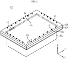
- FIG. 1 is a perspective view schematically showing a battery module according to an embodiment of the present disclosure.
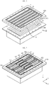
- FIG. 2 is an exploded perspective view schematically showing some components of the battery module according to an embodiment of the present disclosure.
- FIG. 3 is an exploded perspective view schematically showing some components of the battery module according to an embodiment of the present disclosure.
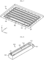
- FIG. 4 is a perspective view schematically showing some components of the battery module according to an embodiment of the present disclosure.
- front and rear directions are expressed in a negative direction and a positive direction of the Y axis
- left and right directions are expressed in a negative direction and a positive direction of the X axis
- upper and lower directions are expressed in a positive direction and a negative direction of the Z axis.
- a battery module 100 includes a cell assembly 110 having a plurality of secondary batteries 111, a lower case 122, an upper case 124, an upper cover 126, and at least one partition member 130.
- the secondary battery 111 may be, for example, a pouch-type secondary battery 111.
- the cell assembly 110 may include 21 pouch-type secondary batteries 111 stacked side by side in one direction (X-axis direction).
- the pouch-type secondary battery 111 may have electrode leads (not shown) provided at front and rear ends thereof, respectively.
- the pouch-type secondary battery 111 may include a positive electrode lead at the front end and a negative electrode lead at the rear end.
- the configuration of the secondary battery 111 is not limited to the pouch-type secondary battery 111 described above, and various types of secondary batteries known at the time of filing of this application may be employed.
- the bus bar assembly 140 may be provided to each of the front side and the rear side of the cell assembly 110.
- the bus bar assembly 140 may be configured to electrically connect the plurality of secondary batteries 111.
- the bus bar assembly 140 may include a bus bar (not shown) configured to contact the electrode leads of the plurality of secondary batteries 111, and a bus bar frame 141 configured to mount the bus bar.
- the bus bar for example, may be made of a metal such as aluminum, copper, nickel.
- the bus bar frame 141 may be made of an electrically insulating material, for example.
- the electrically insulating material may be, for example, polyvinyl chloride.
- the lower case 122 may have an accommodation space S1 in which the cell assembly 110 is accommodated. That is, the lower case 122 may have a rectangular box shape with an open top.
- the lower case 122 may include a sidewall 122a1 provided in a horizontal direction to form an accommodation space S1 of a size corresponding to the cell assembly 110, and a lower wall 122a2 coupled to a lower portion of the sidewall 122a1.
- the lower case 122 may include a flange portion 122b extending in the horizontal direction from an upper end of the sidewall 122a1.
- the flange portion 122b may have a plurality of second bolt holes H4 formed at predetermined intervals along the outer periphery.
- the flange portion 122b may be configured to be bolted to the upper case 124 through the second bolt hole H4 by using a fastening bolt.
- the upper case 124 may have a plate shape extending in the horizontal direction to cover the open top of the lower case 122.
- the upper case 124 may be configured to be coupled to the flange portion 122b of the lower case 122.
- the upper case 124 may have a plurality of first bolt holes H3 formed at the outer periphery in the horizontal direction.
- the upper case 124 may also be configured to be coupled to the upper cover 126.
- the upper case 124 may include a gasket 150 at an upper portion thereof.
- the gasket 150 may be configured to prevent gas from escaping to the outside through the coupling surface between the upper case 124 and the upper cover 126. That is, the gasket 150 may be interposed between the upper case 124 and the upper cover 126.
- the upper cover 126 may have a plate shape extending in the horizontal direction to cover the upper portion of the upper case 124.
- a plurality of third bolt holes H5 spaced apart from each other at a predetermined interval may be formed in the outer periphery of the upper cover 126 in the horizontal direction.
- the upper cover 126 may be coupled to the upper portion of the upper case 124, and the lower portion of the upper case 124 may be coupled to the flange portion 122b of the lower case 122.
- the plurality of bolts B may penetrate through the third bolt hole H5 of the upper cover 126, the first bolt hole H3 of the upper case 124, and the bolt holes H3, H4, and H5 of the lower case 122, respectively.
- the bolt B may be screwed into the bolt holes H3, H4, H5.
- the bolt B may be inserted into the bolt holes H3, H4, H5, and then fastened and fixed by inserting a nut into the lower portion thereof.
- FIG. 5 is a bottom perspective view schematically showing an upper cover of the battery module according to an embodiment of the present disclosure.
- the upper case 124 may have a connection hole H1 by perforating a part thereof to communicate with the accommodation space S1.
- the lower case 122 may form a buffer space S2 spaced apart from the upper case 124.
- the buffer space S2 may be formed by inwardly recessing one surface of at least one of the upper case 124 and the upper cover 126 facing each other.
- a part of the lower surface of the upper cover 126 may have a recessed portion W2 recessed upward, and a part of the upper surface of the upper case 124 may have a recessed portion W2 recessed downward.
- the upper cover 126 may have a discharge hole H2 formed by perforating a part thereof so that the buffer space S2 communicates with the outside. That is, in the battery module 100 of the present disclosure, when thermal runaway or fire occurs in the cell assembly 110 to generate gas from the cell assembly 110, the generated gas may be introduced from the accommodation space S1 into the buffer space S2 through the connection hole H1 of the upper case 124. The gas introduced into the buffer space S2 may be discharged to the outside through the discharge hole H2 of the upper cover 126.
- the buffer space S2 may include at least one partition member 130.
- the partition member 130 may be configured to form a moving passage extending from the connection hole H1 to the discharge hole H2 in the buffer space S2. That is, the partition member 130 may be configured to partition the buffer space S2.
- the partition member 130 may have a shape extending in the horizontal direction in the buffer space S2. For example, as shown in FIG. 4 , five partition members 130 may have a shape extending in the front and rear directions. That is, the partition member 130 may be configured to prevent the gas from moving in the left and right directions (X-axis direction) and to induce the gas to move in the front and rear directions (Y-axis direction).
- the partition member 130 may be configured to adjust the extension length.
- the partition member 130 may adjust the extension length in the front and rear directions (Y-axis direction) according to the set length of the moving passage in the front and rear directions.
- the present disclosure since the buffer space S2 is formed inside by the upper cover 126 and the upper case 124 and also the partition member 130 forms a moving passage in the buffer space S2, when the plurality of secondary batteries 111 of the cell assembly 110 of the battery module 100 explodes or ignites, the generated flame may be extinguished by itself while moving along the moving passage of the buffer space S2, and the gas pressure and gas temperature may drop significantly while the gas generated passes through the moving passage of the buffer space S2. That is, in the present disclosure, without a partition member of the prior art, it is possible to reduce the damage to an external device or human life that may occur when a high-temperature gas or flame is directly discharged from the battery module. Ultimately, the battery module 100 may effectively reduce external damage caused by explosion or fire of the plurality of secondary batteries 111. Accordingly, the present disclosure may significantly increase the safety of the battery module 100.
- the partition member 130 may include at least two barrier units 131, 132, 133. Specifically, some barrier units 132, 133 of the at least two barrier units 131, 132, 133 may be coupled to overlap with each other. Alternatively, some barrier unit 131 of the at least two barrier units 131, 132, 133 may be disposed to be partially separated from other barrier units 132, 133. That is, when the moving passage is lengthened as necessary, the at least two barrier units 131, 132, 133 may be disposed in the buffer space S2 so that the overlapping parts of the at least two barrier units 131, 132, 133 are separated from each other. When the moving passage is shortened as necessary, the at least two barrier units 131, 132, 133 may be disposed in the buffer space S2 so that the at least two barrier units 131, 132, 133 are coupled to overlap with each other.
- ends of the at least two barrier units 131, 132, 133 may be hinged to each other.
- the partition member 130 may include three barrier units 131, 132, 133.
- Each of the three barrier units 131, 132, 133 may be configured to enable hinge rotation.
- One end or both ends of each of the three barrier units 131, 132, 133 may form a hinge-coupling structure 134 with another barrier unit.
- the hinge-coupling structure 134 may include a through hole formed in the barrier unit 131 and a pillar portion inserted into the through hole.
- At least one of the at least two barrier units 131, 132, 133 may have a coupling space S3 formed so that another barrier unit is accommodated therein. That is, in the coupling space S1 of at least one of the at least two barrier units 131, 132, 133, other barrier units may be inserted to overlap with each other. At this time, other barrier units 132 may be inserted into the coupling space S3 of the barrier unit 131 by hinge rotation.
- the partition member 130 since the partition member 130 is disposed so that barrier units 131, 132, 133 overlap with each other or partially separated from each other, when the battery module 100 explodes, the number of barrier units in the partition member 130 and the extended length of the partition member 130 may be adjusted depending on the gas pressure. That is, when the gas pressure of the explosion of the battery module 100 is relatively large, the at least two barrier units 131, 132, 133 of the partition member 130 may be arranged to overlap with each other, and a larger number of barrier units of the partition member 130 may be disposed in the buffer space S2.
- the at least two barrier units 131, 132, 133 of the partition member 130 may be arranged to be partially separated and arranged longer, and a smaller number of barrier units of the partition member 130 may be arranged in the buffer space S2.
- a moving passage along which gas or flame moves may be easily set in consideration of the capacity or explosion characteristics of the applied cell assembly 110, there is no need to manufacture a new battery module 100 whenever it is necessary to change the capacity of the cell assembly 110, which makes it possible to reduce the manufacturing cost and is easy to standardize the partition member 130.
- the partition member 130 may accommodate the plurality of barrier units 131, 132, 133 to overlap with each other, thereby effectively reducing the storage space.
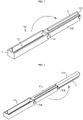
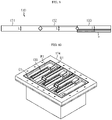
- FIG. 6 is a perspective view schematically showing a partition member of the battery module according to an embodiment of the present disclosure.
- FIG. 7 is a perspective view schematically showing another example of the partition member of the battery module according to an embodiment of the present disclosure.
- FIG. 8 is a perspective view schematically showing still another example of the partition member of the battery module according to an embodiment of the present disclosure.
- the partition member 130 may include a first barrier unit 131, a second barrier unit 132, and a third barrier unit 133.
- the first barrier unit 131 may have both side portions extending in the horizontal direction and spaced apart from each other by a predetermined distance.
- the first barrier unit 131 may have a shape in which extended ends of both side portions are connected to each other.
- the first barrier unit 131 may have a first coupling space S3 opened in upper and lower directions between both side portions.
- the first coupling space S3 may be a space in which the second barrier unit 132 is accommodated.
- the second barrier unit 132 may be moved based on the hinge and inserted into the first coupling space S3.
- an extended end of the second barrier unit 132 may be hinge-coupled to the end of the first barrier unit 131. That is, the second barrier unit 132 may form a hinge-coupling structure 134 with the first barrier unit 131.
- the second barrier unit 132 may be configured to be inserted into the first coupling space S3 formed between both side portions of the first barrier unit 131. That is, the second barrier unit 132 may be rotated based on the hinge and inserted into the first coupling space S3. Alternatively, the second barrier unit 132 may come out of the first coupling space S3 by rotating based on the hinge.
- the second barrier unit 132 may have a second coupling space S4 for accommodating another barrier unit 133.
- the second barrier unit 132 may have a second coupling space S4 for accommodating the third barrier unit 133 therein.
- an extended end of the third barrier unit 133 may be hinge-coupled to the end of the second barrier unit 132.
- the third barrier unit 133 may form a hinge-coupling structure 134 with the second barrier unit 132.
- the third barrier unit 133 may be configured to be inserted into the second coupling space S4 formed between both side portions of the second barrier unit 132.
- the third barrier unit 133 may be rotated based on the hinge and inserted into the second coupling space S4.
- the third barrier unit 133 may come out of the second coupling space S4 by rotating based on the hinge.
- an insert groove G1 may be formed in at least one of the upper cover 126 and the upper case 124 of the battery module 100 of the present disclosure.
- the insert groove G1 may be configured such that the extended end of the barrier unit 133 is inserted therein.
- the insert groove G1 recessed rearward or forward may be formed in a recessed portion W1 of the upper case 124.
- the extended end of the third barrier unit 133 may be inserted.
- an insert groove G1 recessed rearward or forward may be formed in the recessed portion W2 of the upper cover 126.
- the extended end of the first barrier unit 131 or the third barrier unit 133 may be inserted.
- the insert groove G1 is formed, it is possible to fix the end of the partition member 130 in the left and right directions. Accordingly, when the battery module 100 is internally exploded, it is possible to effectively prevent the partition member 130 from being separated from the original position due to the generated gas pressure.
- At least one of the upper cover 126 and the upper case 124 may have a mounting groove G2 configured so that an upper portion or a lower portion of the barrier unit 131 is inserted therein.
- a recessed portion forming the buffer space S2 is formed in the upper direction of the upper cover 126, and a mounting groove G2 recessed upward with a size corresponding to the upper portion of the barrier unit 131 is formed in the recessed portion.
- the mounting groove G2 may be elongated in the front and rear directions from the recessed portion forming the buffer space S2. Five mounting grooves G2 may be formed side by side in the left and right directions.
- the barrier unit 131 may set the position on the mounting groove G2 according to the moving passage to be set. For example, the upper portions of the first barrier unit 131, the second barrier unit 132 and the third barrier unit 133 may be inserted into the mounting grooves G2 of the upper cover 126.
- a recessed portion is provided to form the buffer space S2 in the lower direction of the upper case 124, and a mounting groove G2 recessed downward with a size corresponding to the lower portion of the barrier unit 131 may be formed in the recessed portion.
- the mounting groove G2 may have a shape elongated from the recessed portion in the front and rear directions. Five mounting grooves G2 may be formed side by side in the left and right directions.
- the barrier unit 131 may set the position on the mounting groove G2 according to the moving passage to be set. For example, the lower portions of the first barrier unit 131, the second barrier unit 132 and the third barrier unit 133 may be inserted into the mounting grooves G2 of the upper case 124.
- the end of the partition member 130 may be fixed in the left and right directions. Accordingly, when the battery module 100 is internally exploded, it is possible to effectively prevent the partition member 130 from being separated from the original position due to the generated gas pressure.
- the partition member 130 may have a fixing protrusion P protruding upward or downward.
- the fixing protrusion P may have a shape elongated in the front and rear directions on a plane.
- the fixing protrusion (not shown in FIG. 6 ) may be positioned to protrude downward further to the lower portion of the first barrier unit 131.
- FIG. 6 shows that as shown in FIG. 6
- the fixing protrusion P may be positioned to protrude upward further to the upper portion of the second barrier unit 132.
- the fixing protrusion P may be positioned to protrude downward from the third barrier unit 133.
- the fixing protrusion P may be formed on the third barrier unit 133.
- the upper cover 126 and the upper case 124 may have a fixing groove G3 configured so that the fixing protrusion P is inserted therein.
- the fixing groove G3 may have, for example, a shape elongated in the front and rear directions on a plane.
- the fixing groove G3 may be formed to be recessed upward or downward further to the inner surface of the mounting groove G2.
- a G3 fixing groove recessed upward further to the inner surface of the mounting groove G2 may be formed in the upper cover 126.
- a fixing groove G3 recessed downward further to the inner surface of the mounting groove G2 may be formed in the upper case 124.
- the fixing protrusion P may change the position in the front and rear directions on the fixing groove G3 according to the set moving passage.
- the fixing protrusion P is provided to the partition member 130 and the fixing groove G3 is formed in at least one of the upper cover 126 and the upper case 124, the upper portion or the lower portion of the partition member 130 may be fixed in the left and right directions. Accordingly, when the battery module 100 is internally exploded, it is possible to effectively prevent the partition member 130 from being separated from the original position due to the generated gas pressure.
- FIG. 9 is a side view schematically showing still another example of the partition member of the battery module according to an embodiment of the present disclosure.
- the partition member 130 of the battery module 100 may be exposed to the outside from the mounting groove G2 of each of the at least two barrier units 131, 132, 133 by the same height L. That is, the at least two barrier units 131, 132, 133 may be configured such that the remaining portions exposed from the mounting groove G2 of the partition member 130 have the same height L in a state where they are mounted in the mounting groove G2. For example, as shown in FIG. 9 , the partition member 130 may be configured such that the heights L of the first barrier unit 131, the second barrier unit 132 and the third barrier unit 133 exposed to the outside from the mounting groove G2 may be the same.
- the fixing protrusion P is inserted into the fixing groove G3 formed in the inner surface of the mounting groove G2, and thus the height L is exposed to the outside from the mounting groove G2 of the third barrier unit 133 may be the same as those of the first barrier unit 131 and the second barrier unit 132.
- the battery module 100 of the present disclosure since the at least two barrier units 131, 132, 133 are configured to be exposed to the outside from the mounting groove G2 by the same height L, when the battery module 100 is internally exploded, it is possible to guide the generated gas or flame to move along the set moving passage without leaking to the upper portion or the lower portion of the partition member 130. Accordingly, the battery module 100 of the present disclosure may effectively reduce the extent to which the generated gas or flame is ejected to the outside.
- the battery module 100 of the present disclosure may include five partition members 130.
- any one partition member 130 among the at least two partition members 130 may be disposed to be biased to one side of the buffer space S2 with respect to the center, and the remaining partition member 130 may be disposed to be biased to the other side of the buffer space S2.
- one partition member 130 may be disposed to be biased to one end of the buffer space S2 to form a passage through which flame or gas may pass to the other end of the buffer space S2, and another adjacent partition member 130 may be disposed to be biased toward the other end of the buffer space S2 to form a passage through which gas or flame may pass to one end of the buffer space S2.
- the partition member 130 disposed at the rightmost side may be disposed to be biased toward the front end of the recessed portion of the upper case 124 forming the buffer space S2
- the left partition member 130 adjacent to the partition member 130 disposed at the rightmost side may be disposed to be biased toward the rear end of the recessed portion of the upper case 124 forming the buffer space S2
- the partition member 130 disposed at the center in the left and right directions may be disposed to be biased toward the front end of the recessed portion of the upper case 124
- the left partition member 130 adjacent to the disposed partition member 130 disposed at the center may be disposed to be biased toward the rear end of the recessed portion of the upper case 124 forming the buffer space S2 conversely
- the partition member 130 disposed at the leftmost end may be disposed to be biased toward the front end of the recessed portion of the upper case 124.
- the moving passage since the moving passage is formed in a zigzag shape in the front and rear directions using a plurality of partition members 130, the moving passage may be effectively formed long, so that while the generated gas or passes through the moving passage, the gas pressure may be reduced, and the intensity of the flame may also be effectively reduced. Accordingly, even if a fire or explosion occurs in the battery module 100 of the present disclosure, it is possible to effectively reduce damage caused by gas or flame discharged to the outside.
- FIG. 10 is a perspective view schematically showing some components of a battery module according to another embodiment of the present disclosure.
- the battery module 100 is applied in a case where it has a smaller size than the battery module 100 of FIG. 1 or where a high gas pressure is exerted during explosion, and the first barrier unit 131, the second barrier unit 132 and the third barrier unit 133 of the partition member 130 may be all disposed to overlap with each other.
- five partition members 130 may be mounted in the recessed portion W1 of the upper case 124 to form a moving passage having a zigzag shape in the front and rear directions.
- the five partition members 130 may be arranged such that their ends are alternately inserted into the insert grooves G1 formed at the front or the insert grooves G1 formed at the rear.
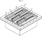
- FIG. 11 is a perspective view schematically showing some components of a battery module according to still another embodiment of the present disclosure.
- the battery module 100 according to another embodiment of the present disclosure is applied in a case where it has a smaller size than the battery module 100 of FIG. 1 but a larger size than the battery module 100 of FIG. 10 or where a lower gas pressure is exerted during explosion than compared to the case of the battery module 100 of FIG. 10 , and in the partition member 130, the second barrier unit 132 and the third barrier unit 133 may be disposed to overlap with each other, and the second barrier unit 132 and the third barrier unit 133 may be disposed to be partially separated from the first barrier unit 131.
- the five partition members 130 may be mounted in the recessed portion W1 of the upper case 124 to form a moving passage of a zigzag shape in the front and rear directions.
- the five partition members 130 may be arranged such that their ends are alternately inserted into the insert grooves G1 formed at the front or the insert grooves G1 formed at the rear.
- a battery pack includes at least one battery module 100 as above.
- the battery pack may further include various devices (not shown) for controlling charging and discharging of the battery module 100, such as a battery management system (BMS), a current sensor, a fuse, and the like.
- BMS battery management system
- an electronic device (not shown) according to an embodiment of the present disclosure includes at least one battery modules 100 as above.
- the electronic device may further include a device housing (not shown) having an accommodation space for accommodating the battery pack, and a display unit through which a user may check the state of charge of the battery pack.
- the battery pack according to an embodiment of the present disclosure may be included in a vehicle such as an electric vehicle or a hybrid electric vehicle. That is, the vehicle according to an embodiment of the present disclosure may have the battery pack according to an embodiment of the present disclosure described above inside a vehicle body.
- Reference Signs 100 battery module 110: cell assembly 111: secondary battery 122: lower case 124: upper case 126: upper cover S1, S2: accommodation space, buffer space H1, H2, H3, H4, H5: connection hole, discharge hole, first bolt hole, second bolt hole, third bolt hole B: bolt 130: partition member 131, 132, 133: first barrier unit, second barrier unit, third barrier unit 134: hinge-coupling structure S3, S4: first coupling space, second coupling space G1, G2, G3: insert groove, mounting groove, fixing groove, P: fixing protrusion L: height 140, 142: bus bar assembly, bus bar frame
Landscapes
- Chemical & Material Sciences (AREA)
- Chemical Kinetics & Catalysis (AREA)
- Electrochemistry (AREA)
- General Chemical & Material Sciences (AREA)
- Engineering & Computer Science (AREA)
- Manufacturing & Machinery (AREA)
- Aviation & Aerospace Engineering (AREA)
- Battery Mounting, Suspending (AREA)
- Gas Exhaust Devices For Batteries (AREA)
Applications Claiming Priority (2)
| Application Number | Priority Date | Filing Date | Title |
|---|---|---|---|
| KR1020200158073A KR20220070959A (ko) | 2020-11-23 | 2020-11-23 | 배터리 모듈, 그것을 포함하는 배터리 팩, 및 자동차 |
| PCT/KR2021/016677 WO2022108281A1 (ko) | 2020-11-23 | 2021-11-15 | 배터리 모듈, 그것을 포함하는 배터리 팩, 및 자동차 |
Publications (3)
| Publication Number | Publication Date |
|---|---|
| EP4087047A1 true EP4087047A1 (de) | 2022-11-09 |
| EP4087047A4 EP4087047A4 (de) | 2023-08-30 |
| EP4087047B1 EP4087047B1 (de) | 2025-01-01 |
Family
ID=81709376
Family Applications (1)
| Application Number | Title | Priority Date | Filing Date |
|---|---|---|---|
| EP21895049.1A Active EP4087047B1 (de) | 2020-11-23 | 2021-11-15 | Batteriemodul, batteriepack damit und fahrzeug. |
Country Status (8)
| Country | Link |
|---|---|
| US (1) | US20230045395A1 (de) |
| EP (1) | EP4087047B1 (de) |
| JP (1) | JP7387904B2 (de) |
| KR (1) | KR20220070959A (de) |
| CN (1) | CN114982056B (de) |
| ES (1) | ES3007648T3 (de) |
| HU (1) | HUE070219T2 (de) |
| WO (1) | WO2022108281A1 (de) |
Cited By (1)
| Publication number | Priority date | Publication date | Assignee | Title |
|---|---|---|---|---|
| EP4080659A4 (de) * | 2020-08-26 | 2023-08-16 | LG Energy Solution, Ltd. | Batteriemodul sowie batteriepack und automobil damit |
Families Citing this family (4)
| Publication number | Priority date | Publication date | Assignee | Title |
|---|---|---|---|---|
| KR20230119551A (ko) * | 2022-02-07 | 2023-08-16 | 주식회사 엘지에너지솔루션 | 배터리 모듈, 이를 포함하는 배터리 팩 및 자동차 |
| KR20240097570A (ko) * | 2022-12-20 | 2024-06-27 | 주식회사 엘지에너지솔루션 | 안전성이 향상된 전지 팩 |
| KR20240131180A (ko) * | 2023-02-23 | 2024-08-30 | 주식회사 엘지에너지솔루션 | 배터리 모듈, 이를 포함하는 배터리 팩 및 자동차 |
| CN120569846A (zh) * | 2023-11-17 | 2025-08-29 | 株式会社Lg新能源 | 电池组和包括该电池组的车辆 |
Family Cites Families (23)
| Publication number | Priority date | Publication date | Assignee | Title |
|---|---|---|---|---|
| US3789906A (en) * | 1972-04-14 | 1974-02-05 | Lignacord Gmbh | Folding wall or door |
| JP2604987Y2 (ja) * | 1993-10-20 | 2000-06-12 | マツダ株式会社 | 電気自動車のバッテリ支持構造 |
| JP4953527B2 (ja) * | 2001-07-27 | 2012-06-13 | パナソニック株式会社 | 電池 |
| US20070262602A1 (en) * | 2005-02-24 | 2007-11-15 | Nagle Rick A | Retractable tailgate barrier and accessory systems |
| JP5507173B2 (ja) * | 2009-09-25 | 2014-05-28 | パナソニック株式会社 | 電池モジュールとそれを用いた電池パック |
| JP6064644B2 (ja) * | 2013-02-08 | 2017-01-25 | 株式会社豊田自動織機 | 電池パック |
| JP6279834B2 (ja) | 2013-02-20 | 2018-02-14 | ホーチキ株式会社 | 蓄電装置及びそれを使用する移動体又は施設 |
| JP6251972B2 (ja) * | 2013-03-29 | 2017-12-27 | 株式会社Gsユアサ | 蓄電装置 |
| JP2015133266A (ja) * | 2014-01-14 | 2015-07-23 | トヨタ自動車株式会社 | 蓄電装置 |
| JP6245478B2 (ja) * | 2014-09-29 | 2017-12-13 | 豊田合成株式会社 | バスバー |
| US9614210B2 (en) * | 2014-09-30 | 2017-04-04 | Johnson Controls Technology Company | Battery module vent system and method |
| US20160218336A1 (en) * | 2015-01-28 | 2016-07-28 | Motorola Solutions, Inc | Method and apparatus for assembling cells in a battery pack to control thermal release |
| JP6365884B2 (ja) * | 2015-04-14 | 2018-08-01 | 豊田合成株式会社 | 組電池 |
| KR102061872B1 (ko) * | 2016-01-28 | 2020-01-02 | 주식회사 엘지화학 | 이차전지 팩 케이스 및 이를 포함하는 이차전지 팩 |
| CN206076341U (zh) * | 2016-09-29 | 2017-04-05 | 宁德时代新能源科技股份有限公司 | 线束板组件及电池模组 |
| WO2018123573A1 (ja) * | 2016-12-27 | 2018-07-05 | パナソニックIpマネジメント株式会社 | 電池モジュール |
| KR101799238B1 (ko) * | 2017-06-09 | 2017-11-17 | 김국현 | 배터리 커버 조립체 |
| KR102033101B1 (ko) * | 2017-09-27 | 2019-10-16 | 주식회사 엘지화학 | 배터리 모듈, 이를 포함하는 배터리 팩 및 자동차 |
| JP2019133856A (ja) * | 2018-01-31 | 2019-08-08 | 株式会社豊田自動織機 | 蓄電装置 |
| KR101998224B1 (ko) * | 2018-11-08 | 2019-07-09 | 정용규 | 공기 순환 냉각 및 피해 저감형 에너지저장시스템 |
| WO2020153018A1 (ja) | 2019-01-25 | 2020-07-30 | 三洋電機株式会社 | パック電池 |
| CN110393875B (zh) * | 2019-08-05 | 2024-10-25 | 清华大学 | 锂离子电池防火装置 |
| KR102844872B1 (ko) * | 2020-04-17 | 2025-08-08 | 주식회사 엘지에너지솔루션 | 화염 배출 방지 구조를 갖는 배터리 모듈, 이를 포함하는 배터리 팩, 자동차 및 전력 저장 시스템 |
-
2020
- 2020-11-23 KR KR1020200158073A patent/KR20220070959A/ko active Pending
-
2021
- 2021-11-15 JP JP2022540563A patent/JP7387904B2/ja active Active
- 2021-11-15 ES ES21895049T patent/ES3007648T3/es active Active
- 2021-11-15 WO PCT/KR2021/016677 patent/WO2022108281A1/ko not_active Ceased
- 2021-11-15 HU HUE21895049A patent/HUE070219T2/hu unknown
- 2021-11-15 EP EP21895049.1A patent/EP4087047B1/de active Active
- 2021-11-15 US US17/790,435 patent/US20230045395A1/en active Pending
- 2021-11-15 CN CN202180010098.7A patent/CN114982056B/zh active Active
Cited By (2)
| Publication number | Priority date | Publication date | Assignee | Title |
|---|---|---|---|---|
| EP4080659A4 (de) * | 2020-08-26 | 2023-08-16 | LG Energy Solution, Ltd. | Batteriemodul sowie batteriepack und automobil damit |
| US12562430B2 (en) | 2020-08-26 | 2026-02-24 | Lg Energy Solution, Ltd. | Battery module, and battery pack and automobile including same |
Also Published As
| Publication number | Publication date |
|---|---|
| CN114982056B (zh) | 2024-07-09 |
| ES3007648T3 (en) | 2025-03-20 |
| EP4087047A4 (de) | 2023-08-30 |
| JP2023509933A (ja) | 2023-03-10 |
| JP7387904B2 (ja) | 2023-11-28 |
| CN114982056A (zh) | 2022-08-30 |
| EP4087047B1 (de) | 2025-01-01 |
| HUE070219T2 (hu) | 2025-05-28 |
| US20230045395A1 (en) | 2023-02-09 |
| KR20220070959A (ko) | 2022-05-31 |
| WO2022108281A1 (ko) | 2022-05-27 |
Similar Documents
| Publication | Publication Date | Title |
|---|---|---|
| EP4087047B1 (de) | Batteriemodul, batteriepack damit und fahrzeug. | |
| JP7527407B2 (ja) | バッテリーモジュール、バッテリーパック、及び自動車 | |
| EP3926735A1 (de) | Batteriepack, elektronische vorrichtung und fahrzeug | |
| JP7549048B2 (ja) | バッテリパック、電力貯蔵装置、及び自動車 | |
| US11552360B2 (en) | Cartridge and battery module comprising same | |
| US12525681B2 (en) | Battery module, battery pack, and vehicle | |
| KR20230152577A (ko) | 배터리 모듈, 배터리 팩 및 이를 포함하는 자동차 | |
| EP4131574B1 (de) | Batteriemodul, batteriepack und elektrisches fahrzeug | |
| US20240405360A1 (en) | Battery module, and battery pack and vehicle comprising the same | |
| EP4576384A1 (de) | Batteriepack | |
| EP4629423A1 (de) | Batteriepack | |
| EP4675817A1 (de) | Batteriepack | |
| KR20250049106A (ko) | 배터리 셀 | |
| KR20240074454A (ko) | 안전성이 강화된 배터리 모듈 | |
| KR20250038076A (ko) | 배터리 팩 |
Legal Events
| Date | Code | Title | Description |
|---|---|---|---|
| STAA | Information on the status of an ep patent application or granted ep patent |
Free format text: STATUS: THE INTERNATIONAL PUBLICATION HAS BEEN MADE |
|
| PUAI | Public reference made under article 153(3) epc to a published international application that has entered the european phase |
Free format text: ORIGINAL CODE: 0009012 |
|
| STAA | Information on the status of an ep patent application or granted ep patent |
Free format text: STATUS: REQUEST FOR EXAMINATION WAS MADE |
|
| 17P | Request for examination filed |
Effective date: 20220802 |
|
| AK | Designated contracting states |
Kind code of ref document: A1 Designated state(s): AL AT BE BG CH CY CZ DE DK EE ES FI FR GB GR HR HU IE IS IT LI LT LU LV MC MK MT NL NO PL PT RO RS SE SI SK SM TR |
|
| A4 | Supplementary search report drawn up and despatched |
Effective date: 20230728 |
|
| RIC1 | Information provided on ipc code assigned before grant |
Ipc: H01M 50/35 20210101ALI20230724BHEP Ipc: H01M 50/342 20210101ALI20230724BHEP Ipc: H01M 50/30 20210101ALI20230724BHEP Ipc: H01M 50/291 20210101ALI20230724BHEP Ipc: H01M 50/264 20210101ALI20230724BHEP Ipc: H01M 10/658 20140101ALI20230724BHEP Ipc: H01M 10/647 20140101ALI20230724BHEP Ipc: H01M 10/613 20140101ALI20230724BHEP Ipc: H01M 50/211 20210101ALI20230724BHEP Ipc: H01M 50/249 20210101ALI20230724BHEP Ipc: H01M 50/271 20210101ALI20230724BHEP Ipc: H01M 50/308 20210101ALI20230724BHEP Ipc: H01M 50/358 20210101AFI20230724BHEP |
|
| DAV | Request for validation of the european patent (deleted) | ||
| DAX | Request for extension of the european patent (deleted) | ||
| RIC1 | Information provided on ipc code assigned before grant |
Ipc: H01M 50/35 20210101ALI20240405BHEP Ipc: H01M 50/342 20210101ALI20240405BHEP Ipc: H01M 50/30 20210101ALI20240405BHEP Ipc: H01M 50/291 20210101ALI20240405BHEP Ipc: H01M 50/264 20210101ALI20240405BHEP Ipc: H01M 10/658 20140101ALI20240405BHEP Ipc: H01M 10/647 20140101ALI20240405BHEP Ipc: H01M 10/613 20140101ALI20240405BHEP Ipc: H01M 50/211 20210101ALI20240405BHEP Ipc: H01M 50/249 20210101ALI20240405BHEP Ipc: H01M 50/271 20210101ALI20240405BHEP Ipc: H01M 50/308 20210101ALI20240405BHEP Ipc: H01M 50/358 20210101AFI20240405BHEP |
|
| GRAP | Despatch of communication of intention to grant a patent |
Free format text: ORIGINAL CODE: EPIDOSNIGR1 |
|
| STAA | Information on the status of an ep patent application or granted ep patent |
Free format text: STATUS: GRANT OF PATENT IS INTENDED |
|
| INTG | Intention to grant announced |
Effective date: 20240524 |
|
| P01 | Opt-out of the competence of the unified patent court (upc) registered |
Free format text: CASE NUMBER: APP_33846/2024 Effective date: 20240606 |
|
| GRAS | Grant fee paid |
Free format text: ORIGINAL CODE: EPIDOSNIGR3 |
|
| GRAJ | Information related to disapproval of communication of intention to grant by the applicant or resumption of examination proceedings by the epo deleted |
Free format text: ORIGINAL CODE: EPIDOSDIGR1 |
|
| GRAL | Information related to payment of fee for publishing/printing deleted |
Free format text: ORIGINAL CODE: EPIDOSDIGR3 |
|
| STAA | Information on the status of an ep patent application or granted ep patent |
Free format text: STATUS: REQUEST FOR EXAMINATION WAS MADE |
|
| GRAP | Despatch of communication of intention to grant a patent |
Free format text: ORIGINAL CODE: EPIDOSNIGR1 |
|
| INTC | Intention to grant announced (deleted) | ||
| STAA | Information on the status of an ep patent application or granted ep patent |
Free format text: STATUS: GRANT OF PATENT IS INTENDED |
|
| GRAA | (expected) grant |
Free format text: ORIGINAL CODE: 0009210 |
|
| STAA | Information on the status of an ep patent application or granted ep patent |
Free format text: STATUS: THE PATENT HAS BEEN GRANTED |
|
| INTG | Intention to grant announced |
Effective date: 20241031 |
|
| AK | Designated contracting states |
Kind code of ref document: B1 Designated state(s): AL AT BE BG CH CY CZ DE DK EE ES FI FR GB GR HR HU IE IS IT LI LT LU LV MC MK MT NL NO PL PT RO RS SE SI SK SM TR |
|
| REG | Reference to a national code |
Ref country code: GB Ref legal event code: FG4D |
|
| REG | Reference to a national code |
Ref country code: DE Ref legal event code: R096 Ref document number: 602021024502 Country of ref document: DE |
|
| REG | Reference to a national code |
Ref country code: CH Ref legal event code: EP |
|
| REG | Reference to a national code |
Ref country code: IE Ref legal event code: FG4D |
|
| REG | Reference to a national code |
Ref country code: ES Ref legal event code: FG2A Ref document number: 3007648 Country of ref document: ES Kind code of ref document: T3 Effective date: 20250320 |
|
| REG | Reference to a national code |
Ref country code: LT Ref legal event code: MG9D |
|
| REG | Reference to a national code |
Ref country code: NL Ref legal event code: MP Effective date: 20250101 |
|
| REG | Reference to a national code |
Ref country code: HU Ref legal event code: AG4A Ref document number: E070219 Country of ref document: HU |
|
| REG | Reference to a national code |
Ref country code: AT Ref legal event code: MK05 Ref document number: 1757264 Country of ref document: AT Kind code of ref document: T Effective date: 20250101 |
|
| PG25 | Lapsed in a contracting state [announced via postgrant information from national office to epo] |
Ref country code: NL Free format text: LAPSE BECAUSE OF FAILURE TO SUBMIT A TRANSLATION OF THE DESCRIPTION OR TO PAY THE FEE WITHIN THE PRESCRIBED TIME-LIMIT Effective date: 20250101 |
|
| PG25 | Lapsed in a contracting state [announced via postgrant information from national office to epo] |
Ref country code: FI Free format text: LAPSE BECAUSE OF FAILURE TO SUBMIT A TRANSLATION OF THE DESCRIPTION OR TO PAY THE FEE WITHIN THE PRESCRIBED TIME-LIMIT Effective date: 20250101 |
|
| PG25 | Lapsed in a contracting state [announced via postgrant information from national office to epo] |
Ref country code: PL Free format text: LAPSE BECAUSE OF FAILURE TO SUBMIT A TRANSLATION OF THE DESCRIPTION OR TO PAY THE FEE WITHIN THE PRESCRIBED TIME-LIMIT Effective date: 20250101 |
|
| PG25 | Lapsed in a contracting state [announced via postgrant information from national office to epo] |
Ref country code: NO Free format text: LAPSE BECAUSE OF FAILURE TO SUBMIT A TRANSLATION OF THE DESCRIPTION OR TO PAY THE FEE WITHIN THE PRESCRIBED TIME-LIMIT Effective date: 20250401 Ref country code: IS Free format text: LAPSE BECAUSE OF FAILURE TO SUBMIT A TRANSLATION OF THE DESCRIPTION OR TO PAY THE FEE WITHIN THE PRESCRIBED TIME-LIMIT Effective date: 20250501 |
|
| PG25 | Lapsed in a contracting state [announced via postgrant information from national office to epo] |
Ref country code: HR Free format text: LAPSE BECAUSE OF FAILURE TO SUBMIT A TRANSLATION OF THE DESCRIPTION OR TO PAY THE FEE WITHIN THE PRESCRIBED TIME-LIMIT Effective date: 20250101 |
|
| PG25 | Lapsed in a contracting state [announced via postgrant information from national office to epo] |
Ref country code: LV Free format text: LAPSE BECAUSE OF FAILURE TO SUBMIT A TRANSLATION OF THE DESCRIPTION OR TO PAY THE FEE WITHIN THE PRESCRIBED TIME-LIMIT Effective date: 20250101 Ref country code: PT Free format text: LAPSE BECAUSE OF FAILURE TO SUBMIT A TRANSLATION OF THE DESCRIPTION OR TO PAY THE FEE WITHIN THE PRESCRIBED TIME-LIMIT Effective date: 20250502 |
|
| PG25 | Lapsed in a contracting state [announced via postgrant information from national office to epo] |
Ref country code: BG Free format text: LAPSE BECAUSE OF FAILURE TO SUBMIT A TRANSLATION OF THE DESCRIPTION OR TO PAY THE FEE WITHIN THE PRESCRIBED TIME-LIMIT Effective date: 20250101 Ref country code: GR Free format text: LAPSE BECAUSE OF FAILURE TO SUBMIT A TRANSLATION OF THE DESCRIPTION OR TO PAY THE FEE WITHIN THE PRESCRIBED TIME-LIMIT Effective date: 20250402 |
|
| PG25 | Lapsed in a contracting state [announced via postgrant information from national office to epo] |
Ref country code: AT Free format text: LAPSE BECAUSE OF FAILURE TO SUBMIT A TRANSLATION OF THE DESCRIPTION OR TO PAY THE FEE WITHIN THE PRESCRIBED TIME-LIMIT Effective date: 20250101 |
|
| PG25 | Lapsed in a contracting state [announced via postgrant information from national office to epo] |
Ref country code: CZ Free format text: LAPSE BECAUSE OF FAILURE TO SUBMIT A TRANSLATION OF THE DESCRIPTION OR TO PAY THE FEE WITHIN THE PRESCRIBED TIME-LIMIT Effective date: 20250101 |
|
| PG25 | Lapsed in a contracting state [announced via postgrant information from national office to epo] |
Ref country code: SE Free format text: LAPSE BECAUSE OF FAILURE TO SUBMIT A TRANSLATION OF THE DESCRIPTION OR TO PAY THE FEE WITHIN THE PRESCRIBED TIME-LIMIT Effective date: 20250101 |
|
| REG | Reference to a national code |
Ref country code: DE Ref legal event code: R097 Ref document number: 602021024502 Country of ref document: DE |
|
| PG25 | Lapsed in a contracting state [announced via postgrant information from national office to epo] |
Ref country code: SM Free format text: LAPSE BECAUSE OF FAILURE TO SUBMIT A TRANSLATION OF THE DESCRIPTION OR TO PAY THE FEE WITHIN THE PRESCRIBED TIME-LIMIT Effective date: 20250101 |
|
| PG25 | Lapsed in a contracting state [announced via postgrant information from national office to epo] |
Ref country code: DK Free format text: LAPSE BECAUSE OF FAILURE TO SUBMIT A TRANSLATION OF THE DESCRIPTION OR TO PAY THE FEE WITHIN THE PRESCRIBED TIME-LIMIT Effective date: 20250101 |
|
| PG25 | Lapsed in a contracting state [announced via postgrant information from national office to epo] |
Ref country code: IT Free format text: LAPSE BECAUSE OF FAILURE TO SUBMIT A TRANSLATION OF THE DESCRIPTION OR TO PAY THE FEE WITHIN THE PRESCRIBED TIME-LIMIT Effective date: 20250101 |
|
| PG25 | Lapsed in a contracting state [announced via postgrant information from national office to epo] |
Ref country code: EE Free format text: LAPSE BECAUSE OF FAILURE TO SUBMIT A TRANSLATION OF THE DESCRIPTION OR TO PAY THE FEE WITHIN THE PRESCRIBED TIME-LIMIT Effective date: 20250101 |
|
| PG25 | Lapsed in a contracting state [announced via postgrant information from national office to epo] |
Ref country code: RO Free format text: LAPSE BECAUSE OF FAILURE TO SUBMIT A TRANSLATION OF THE DESCRIPTION OR TO PAY THE FEE WITHIN THE PRESCRIBED TIME-LIMIT Effective date: 20250101 |
|
| PG25 | Lapsed in a contracting state [announced via postgrant information from national office to epo] |
Ref country code: SK Free format text: LAPSE BECAUSE OF FAILURE TO SUBMIT A TRANSLATION OF THE DESCRIPTION OR TO PAY THE FEE WITHIN THE PRESCRIBED TIME-LIMIT Effective date: 20250101 |
|
| PLBE | No opposition filed within time limit |
Free format text: ORIGINAL CODE: 0009261 |
|
| STAA | Information on the status of an ep patent application or granted ep patent |
Free format text: STATUS: NO OPPOSITION FILED WITHIN TIME LIMIT |
|
| 26N | No opposition filed |
Effective date: 20251002 |
|
| PGFP | Annual fee paid to national office [announced via postgrant information from national office to epo] |
Ref country code: HU Payment date: 20251127 Year of fee payment: 5 |
|
| PGFP | Annual fee paid to national office [announced via postgrant information from national office to epo] |
Ref country code: DE Payment date: 20251020 Year of fee payment: 5 |
|
| PGFP | Annual fee paid to national office [announced via postgrant information from national office to epo] |
Ref country code: GB Payment date: 20251023 Year of fee payment: 5 |
|
| PGFP | Annual fee paid to national office [announced via postgrant information from national office to epo] |
Ref country code: FR Payment date: 20251021 Year of fee payment: 5 |
|
| PGFP | Annual fee paid to national office [announced via postgrant information from national office to epo] |
Ref country code: BE Payment date: 20251020 Year of fee payment: 5 |
|
| PGFP | Annual fee paid to national office [announced via postgrant information from national office to epo] |
Ref country code: ES Payment date: 20251215 Year of fee payment: 5 |