EP4087057B1 - Gruppenantenne - Google Patents
Gruppenantenne Download PDFInfo
- Publication number
- EP4087057B1 EP4087057B1 EP20909313.7A EP20909313A EP4087057B1 EP 4087057 B1 EP4087057 B1 EP 4087057B1 EP 20909313 A EP20909313 A EP 20909313A EP 4087057 B1 EP4087057 B1 EP 4087057B1
- Authority
- EP
- European Patent Office
- Prior art keywords
- feed
- substrate
- line layer
- dielectric
- network line
- Prior art date
- Legal status (The legal status is an assumption and is not a legal conclusion. Google has not performed a legal analysis and makes no representation as to the accuracy of the status listed.)
- Active
Links
Images



Classifications
-
- H—ELECTRICITY
- H01—ELECTRIC ELEMENTS
- H01Q—ANTENNAS, i.e. RADIO AERIALS
- H01Q1/00—Details of, or arrangements associated with, antennas
- H01Q1/36—Structural form of radiating elements, e.g. cone, spiral, umbrella; Particular materials used therewith
- H01Q1/38—Structural form of radiating elements, e.g. cone, spiral, umbrella; Particular materials used therewith formed by a conductive layer on an insulating support
-
- H—ELECTRICITY
- H01—ELECTRIC ELEMENTS
- H01Q—ANTENNAS, i.e. RADIO AERIALS
- H01Q1/00—Details of, or arrangements associated with, antennas
- H01Q1/12—Supports; Mounting means
- H01Q1/22—Supports; Mounting means by structural association with other equipment or articles
- H01Q1/24—Supports; Mounting means by structural association with other equipment or articles with receiving set
- H01Q1/241—Supports; Mounting means by structural association with other equipment or articles with receiving set used in mobile communications, e.g. GSM
- H01Q1/246—Supports; Mounting means by structural association with other equipment or articles with receiving set used in mobile communications, e.g. GSM specially adapted for base stations
-
- H—ELECTRICITY
- H01—ELECTRIC ELEMENTS
- H01Q—ANTENNAS, i.e. RADIO AERIALS
- H01Q1/00—Details of, or arrangements associated with, antennas
- H01Q1/50—Structural association of antennas with earthing switches, lead-in devices or lightning protectors
-
- H—ELECTRICITY
- H01—ELECTRIC ELEMENTS
- H01Q—ANTENNAS, i.e. RADIO AERIALS
- H01Q1/00—Details of, or arrangements associated with, antennas
- H01Q1/52—Means for reducing coupling between antennas; Means for reducing coupling between an antenna and another structure
- H01Q1/526—Electromagnetic shields
-
- H—ELECTRICITY
- H01—ELECTRIC ELEMENTS
- H01Q—ANTENNAS, i.e. RADIO AERIALS
- H01Q21/00—Antenna arrays or systems
- H01Q21/0006—Particular feeding systems
-
- H—ELECTRICITY
- H01—ELECTRIC ELEMENTS
- H01Q—ANTENNAS, i.e. RADIO AERIALS
- H01Q21/00—Antenna arrays or systems
- H01Q21/06—Arrays of individually energised antenna units similarly polarised and spaced apart
- H01Q21/061—Two dimensional planar arrays
- H01Q21/065—Patch antenna array
-
- H—ELECTRICITY
- H01—ELECTRIC ELEMENTS
- H01Q—ANTENNAS, i.e. RADIO AERIALS
- H01Q21/00—Antenna arrays or systems
- H01Q21/0006—Particular feeding systems
- H01Q21/0075—Stripline fed arrays
Definitions
- the present application relates to the field of mobile communication technology, and in particular, to an array antenna.
- FIG. 110011072A discloses an integrated Massive MIMO antenna including a reflector, one side of which is provided with a power distribution network PCB board, and the other side of the reflector is provided with a calibration network PCB board, a power distribution network PCB board, a reflection board, and a calibration network PCB.
- the document further describes antenna performance test points, filter performance test points and antenna performance test points for the integrated Massive MIMO antenna.
- An array antenna comprises:
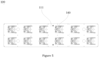
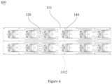
- the dielectric substrate comprises a feed substrate and a radiation substrate disposed on one side of the feed substrate and integrally formed with the feed substrate, wherein, the feed network line layer is formed on a surface of the feed substrate, the radiation substrate is coated with a metal layer on a surface to form the radiation unit.
- the feed network line layer is disposed on a surface of the feed substrate facing away from the radiation unit.
- the array antenna further comprises a circuit board, wherein, the plurality of dielectric filter modules are integrated in the circuit board, and the outputs of the plurality of dielectric filter modules are electrically connected to the feed network line layer through the circuit board.
- the dielectric substrate is formed with raised ribs on a surface toward the reflective plate, and the ribs are abutted against the reflective plate.
- the shield is coated with a conductive adhesive on an end surface of the opening.
- the feed network line layer can be formed on the surface of the dielectric substrate by means of coating, etc. Therefore, it is equivalent to integrating the feed network and radiation unit of the conventional antenna on the dielectric substrate.
- the shielding cavity provides shielding to the dielectric filter module inside, so multiple dielectric filter modules with the shielding cavity can be functionally equivalent to the traditional multiple dielectric filters.
- each shielding cavity houses at least two dielectric filter modules, so the number of shielding cavities can be much less than the number of dielectric filter module. Compared with the traditional way of directly mounting dielectric filters, more metal shielding cavities can be omitted. Therefore, the above array antenna can achieve light weight.
- an array antenna 10 in the preferred embodiment of the present application includes an antenna oscillator module 100, a shielding cavity 200, and a dielectric filter module 300.
- the antenna oscillator module 100 includes a dielectric substrate 110, a feed network line layer 120, and a radiation unit 130.
- the antenna oscillator module 100 generally has multiple signal channels. For example, there are common 32 channels, 64 channels. Each signal channel contains at least one radiation unit 130. As shown in FIGS. 2 and 3 , in the embodiment, the number of radiation unit 130 is 96, and each signal channel contains three radiation units 130. Therefore, the array antenna 10 is a 32-channel antenna.
- the dielectric substrate 110 is a one-piece structure, and its material can be plastic, resin, etc. Usually, the dielectric substrate 110 is molded in one piece by injection molding.
- the feed network line layer 120 is formed on the surface of the dielectric substrate 110.
- the feed network line layer 120 can integrate functional circuit such as divider circuit, filter circuit, etc., which can be used to feed the radiation unit 120, and is therefore equivalent to a conventional feed network.
- the feed network line layer 120 can be formed on the surface of the dielectric substrate 110 by means of selective plating, LDS (laser direct forming technology) and other surface metal forming, and can be made of copper, silver and other good conductors.
- the radiation unit 130 is used for receiving and radiating electromagnetic wave signals outward, generally using a dual-polarized radiation unit.
- the radiation unit 130 is provided on one side of the dielectric substrate 110, and is fed by the feed network line layer 120.
- the feed network line layer 120 can be directly fed to the radiation unit 130, can also be coupled to the radiation unit 130 for feed.
- a feed structure line layer 140 may also be formed on the dielectric substrate 110 at the same time, and the feed structure line layer 140 is supported by the dielectric substrate 110, which is equivalent to the traditional feed balun and feed column.
- the reflective plate 500 is generally a metal reflective plate, which can reflect the electromagnetic wave signal several times, thus enhancing the efficiency of signal transmitting and receiving of the radiation unit 130.
- the surface profile of the reflective plate 500 is generally substantially the same as the surface profile of the dielectric substrate 110, and the surfaces of both are disposed opposite each other.
- the reflective plate 500 can be screwed, welded and other ways to achieve installation with the dielectric substrate 110.
Landscapes
- Physics & Mathematics (AREA)
- Electromagnetism (AREA)
- Engineering & Computer Science (AREA)
- Computer Networks & Wireless Communication (AREA)
- Variable-Direction Aerials And Aerial Arrays (AREA)
- Waveguide Aerials (AREA)
Claims (7)
- Gruppenantenne (10), umfassend:ein Antennenoszillatormodul (100), das ein dielektrisches Substrat (110), eine auf einer Fläche des dielektrischen Substrats (110) ausgebildete Speisenetzleitungsschicht (120) und eine Vielzahl von Strahlungseinheiten (130) umfasst, die auf einer Seite des dielektrischen Substrats (110) angeordnet sind und von der Speisenetzleitungsschicht (120) gespeist werden;einen abschirmenden Hohlraum (200), der auf einer Seite des dielektrischen Substrats (110) ausgebildet ist und der Strahlungseinheit (130) abgewandt ist; undeine Vielzahl von dielektrischen Filtermodulen (300), die in dem abschirmenden Hohlraum (200) angeordnet sind, wobei jeder abschirmende Hohlraum (200) mindestens zwei der dielektrischen Filtermodule (300) aufnimmt, wobei ein Ausgang jedes der dielektrischen Filtermodule (300) elektrisch mit der Speisenetzleitungsschicht (120) verbunden ist;eine reflektierende Platte (500), die auf einer der Strahlungseinheit (130) abgewandten Seite des dielektrischen Substrats (110) befestigt ist;eine Abschirmung (600) mit einer Öffnung auf einer Seite, wobei die Abschirmung (600) auf einer Fläche der reflektierenden Platte (500) vorgesehen ist, die dem Antennenoszillatormodul (100) abgewandt ist und mit der reflektierenden Platte (500) zusammenwirkt, um den abschirmenden Hohlraum (200) zu bilden;wobei eine Innenwand der Abschirmung (600) mit einem leitfähigen Schaum (620) versehen ist, der an dem dielektrischen Filtermodul (300) anliegt.
- Gruppenantenne (10) nach Anspruch 1, wobei das dielektrische Substrat (110) ein Einspeisesubstrat (111) und ein Strahlungssubstrat (113) umfasst, das auf einer Seite des Einspeisesubstrats (111) angeordnet und einstückig mit dem Einspeisesubstrat (111) ausgebildet ist, wobei die Speisenetzleitungsschicht (120) auf einer Fläche des Einspeisesubstrats (111) ausgebildet ist, das Strahlungssubstrat (113) auf einer Fläche mit einer Metallschicht beschichtet ist, um die Strahlungseinheit (130) zu bilden.
- Gruppenantenne (10) nach Anspruch 2, wobei die Speisenetzleitungsschicht (120) auf einer Fläche des Einspeisesubstrats (111) angeordnet ist, die der Strahlungseinheit (130) abgewandt ist,
oder die Speisenetzleitungsschicht (120) ist auf einer der Strahlungseinheit (130) zugewandten Fläche des Einspeisesubstrats (111) angeordnet. - Gruppenantenne (10) nach Anspruch 1, ferner umfassend: eine Leiterplatte (400), wobei die Vielzahl der dielektrischen Filtermodule (300) in die Leiterplatte (400) integriert ist und die Ausgänge der Vielzahl der dielektrischen Filtermodule (300) über die Leiterplatte (400) elektrisch mit der Speisenetzleitungsschicht (120) verbunden ist.
- Gruppenantenne (10) nach Anspruch 4, wobei die Leiterplatte (400) mit HF-Anschlüssen (410) und Einspeisungsstiften (420) versehen ist, die der Vielzahl von dielektrischen Filtermodulen (300) einzeln auf gegenüberliegenden Seiten entsprechen, wobei die Speisenetzleitungsschicht (120) mit Einspeisungslöchern ausgebildet ist und die Einspeisungsstifte (420) in die Einspeisungslöcher eingesetzt sind, um die Vielzahl von dielektrischen Filtermodulen (300) mit der Speisenetzleitungsschicht (120) elektrisch zu verbinden.
- Gruppenantenne (10) nach Anspruch 1, wobei das dielektrische Substrat (110) mit erhöhten Rippen (1112) auf einer Fläche zur reflektierenden Platte (500) hin ausgebildet ist und die Rippen an der reflektierenden Platte (500) anliegen.
- Gruppenantenne (10) nach Anspruch 1, wobei die Abschirmung (600) mit einem leitfähigen Klebstoff (610) auf einer Endfläche der Öffnung beschichtet ist.
Applications Claiming Priority (2)
| Application Number | Priority Date | Filing Date | Title |
|---|---|---|---|
| CN201911417972.XA CN111063997B (zh) | 2019-12-31 | 2019-12-31 | 阵列天线 |
| PCT/CN2020/110270 WO2021135266A1 (zh) | 2019-12-31 | 2020-08-20 | 阵列天线 |
Publications (4)
| Publication Number | Publication Date |
|---|---|
| EP4087057A1 EP4087057A1 (de) | 2022-11-09 |
| EP4087057A4 EP4087057A4 (de) | 2023-01-18 |
| EP4087057C0 EP4087057C0 (de) | 2025-07-02 |
| EP4087057B1 true EP4087057B1 (de) | 2025-07-02 |
Family
ID=70305874
Family Applications (1)
| Application Number | Title | Priority Date | Filing Date |
|---|---|---|---|
| EP20909313.7A Active EP4087057B1 (de) | 2019-12-31 | 2020-08-20 | Gruppenantenne |
Country Status (3)
| Country | Link |
|---|---|
| EP (1) | EP4087057B1 (de) |
| CN (1) | CN111063997B (de) |
| WO (1) | WO2021135266A1 (de) |
Families Citing this family (8)
| Publication number | Priority date | Publication date | Assignee | Title |
|---|---|---|---|---|
| CN112490646B (zh) | 2019-09-12 | 2023-12-15 | 华为技术有限公司 | 一种天线和天线的加工方法 |
| CN111063997B (zh) * | 2019-12-31 | 2024-12-20 | 京信通信技术(广州)有限公司 | 阵列天线 |
| CN111585007B (zh) * | 2020-05-08 | 2022-04-15 | 武汉虹信科技发展有限责任公司 | 高集成mimo天线 |
| WO2021241993A1 (ko) * | 2020-05-26 | 2021-12-02 | 주식회사 케이엠더블유 | 안테나 장치 |
| CN111668605B (zh) * | 2020-07-02 | 2021-07-09 | 中信科移动通信技术股份有限公司 | 用于高铁沿线的电调天线 |
| WO2023123298A1 (zh) * | 2021-12-31 | 2023-07-06 | 京东方科技集团股份有限公司 | 透明振子单元、透明天线及天线系统 |
| CN116454605B (zh) * | 2023-04-03 | 2025-12-30 | 中天通信技术有限公司 | 壁挂天线 |
| CN119234353B (zh) | 2023-04-28 | 2026-01-16 | 京东方科技集团股份有限公司 | 天线及电子设备 |
Family Cites Families (9)
| Publication number | Priority date | Publication date | Assignee | Title |
|---|---|---|---|---|
| CN1893179A (zh) * | 2005-07-08 | 2007-01-10 | 福讯通讯股份有限公司 | 手持装置天线 |
| CN107706544B (zh) * | 2017-09-07 | 2021-01-26 | 广东通宇通讯股份有限公司 | 基站天线及其天线阵列模块 |
| CN109616759B (zh) * | 2018-12-06 | 2020-08-25 | 西南电子技术研究所(中国电子科技集团公司第十研究所) | 全双工有源相控阵滤波天线阵面 |
| CN109713432A (zh) * | 2019-01-14 | 2019-05-03 | 深圳市信维通信股份有限公司 | 5g mimo天线系统及手持设备 |
| CN110011072B (zh) * | 2019-02-22 | 2024-02-20 | 广东通宇通讯股份有限公司 | 一种集成化Massive MIMO天线 |
| CN110323565A (zh) * | 2019-04-30 | 2019-10-11 | 深圳市大富科技股份有限公司 | 一种基站天线以及用于基站的有源天线单元 |
| CN110323556A (zh) * | 2019-05-08 | 2019-10-11 | 深圳市大富科技股份有限公司 | 一种用于基站的有源天线单元及天线单元 |
| CN111063997B (zh) * | 2019-12-31 | 2024-12-20 | 京信通信技术(广州)有限公司 | 阵列天线 |
| CN211126065U (zh) * | 2019-12-31 | 2020-07-28 | 京信通信技术(广州)有限公司 | 阵列天线 |
-
2019
- 2019-12-31 CN CN201911417972.XA patent/CN111063997B/zh active Active
-
2020
- 2020-08-20 WO PCT/CN2020/110270 patent/WO2021135266A1/zh not_active Ceased
- 2020-08-20 EP EP20909313.7A patent/EP4087057B1/de active Active
Also Published As
| Publication number | Publication date |
|---|---|
| CN111063997B (zh) | 2024-12-20 |
| WO2021135266A1 (zh) | 2021-07-08 |
| EP4087057C0 (de) | 2025-07-02 |
| EP4087057A1 (de) | 2022-11-09 |
| EP4087057A4 (de) | 2023-01-18 |
| CN111063997A (zh) | 2020-04-24 |
Similar Documents
| Publication | Publication Date | Title |
|---|---|---|
| EP4087057B1 (de) | Gruppenantenne | |
| CN111129737B (zh) | 天线单元及阵列天线 | |
| JP7246490B2 (ja) | アンテナ構造及び高周波多周波数帯無線通信端末 | |
| US7483728B2 (en) | Portable communication unit and internal antenna used for same | |
| KR102168317B1 (ko) | 이동 단말 및 이동 단말의 안테나 방사 방법 | |
| US20230163441A1 (en) | Antenna device | |
| KR20170083949A (ko) | 누설파 위상 어레이 안테나를 포함하는 무선 통신 장치 | |
| CN109494489B (zh) | 滤波集成式基站天线 | |
| WO2022042239A1 (zh) | 按键、卡托、摄像头装饰件及移动终端 | |
| CN210692758U (zh) | 集成滤波器的天线 | |
| CN111987410A (zh) | 一种模块化afu结构 | |
| CN110911837B (zh) | 集成滤波器的天线 | |
| US6943738B1 (en) | Compact multiband inverted-F antenna | |
| CN117353051A (zh) | 电子设备 | |
| CN211126054U (zh) | 天线单元及阵列天线 | |
| US5276457A (en) | Integrated antenna-converter system in a unitary package | |
| CN212412206U (zh) | 馈电网络、天线系统及基站 | |
| CN114171912A (zh) | Uwb贴片天线、天线结构、壳体组件以及电子设备 | |
| CN210957014U (zh) | 移相馈电装置、天线单元及阵列天线 | |
| US12603431B2 (en) | Antenna element and antenna array | |
| KR102528198B1 (ko) | 안테나 장치 | |
| CN211126065U (zh) | 阵列天线 | |
| KR102266811B1 (ko) | 통신 디바이스 및 통신 디바이스를 조립하기 위한 방법 | |
| CN216052569U (zh) | 拍摄装置 | |
| CN112201942B (zh) | 一种有源天线单元 |
Legal Events
| Date | Code | Title | Description |
|---|---|---|---|
| STAA | Information on the status of an ep patent application or granted ep patent |
Free format text: STATUS: THE INTERNATIONAL PUBLICATION HAS BEEN MADE |
|
| PUAI | Public reference made under article 153(3) epc to a published international application that has entered the european phase |
Free format text: ORIGINAL CODE: 0009012 |
|
| STAA | Information on the status of an ep patent application or granted ep patent |
Free format text: STATUS: REQUEST FOR EXAMINATION WAS MADE |
|
| 17P | Request for examination filed |
Effective date: 20220711 |
|
| AK | Designated contracting states |
Kind code of ref document: A1 Designated state(s): AL AT BE BG CH CY CZ DE DK EE ES FI FR GB GR HR HU IE IS IT LI LT LU LV MC MK MT NL NO PL PT RO RS SE SI SK SM TR |
|
| REG | Reference to a national code |
Ref country code: DE Ref legal event code: R079 Free format text: PREVIOUS MAIN CLASS: H01Q0001380000 Ipc: H01Q0021000000 Ref document number: 602020054014 Country of ref document: DE |
|
| A4 | Supplementary search report drawn up and despatched |
Effective date: 20221216 |
|
| RIC1 | Information provided on ipc code assigned before grant |
Ipc: H01Q 21/06 20060101ALI20221212BHEP Ipc: H01Q 1/24 20060101ALI20221212BHEP Ipc: H01Q 1/52 20060101ALI20221212BHEP Ipc: H01Q 21/00 20060101AFI20221212BHEP |
|
| DAV | Request for validation of the european patent (deleted) | ||
| DAX | Request for extension of the european patent (deleted) | ||
| P01 | Opt-out of the competence of the unified patent court (upc) registered |
Effective date: 20230517 |
|
| REG | Reference to a national code |
Ref country code: DE Ref legal event code: R079 Free format text: PREVIOUS MAIN CLASS: H01Q0021000000 Ipc: H01Q0001240000 Ref document number: 602020054014 Country of ref document: DE |
|
| RIC1 | Information provided on ipc code assigned before grant |
Ipc: H01Q 21/00 20060101ALN20250114BHEP Ipc: H01Q 21/06 20060101ALI20250114BHEP Ipc: H01Q 1/52 20060101ALI20250114BHEP Ipc: H01Q 1/24 20060101AFI20250114BHEP |
|
| RIC1 | Information provided on ipc code assigned before grant |
Ipc: H01Q 21/00 20060101ALN20250127BHEP Ipc: H01Q 21/06 20060101ALI20250127BHEP Ipc: H01Q 1/52 20060101ALI20250127BHEP Ipc: H01Q 1/24 20060101AFI20250127BHEP |
|
| GRAP | Despatch of communication of intention to grant a patent |
Free format text: ORIGINAL CODE: EPIDOSNIGR1 |
|
| STAA | Information on the status of an ep patent application or granted ep patent |
Free format text: STATUS: GRANT OF PATENT IS INTENDED |
|
| INTG | Intention to grant announced |
Effective date: 20250310 |
|
| GRAS | Grant fee paid |
Free format text: ORIGINAL CODE: EPIDOSNIGR3 |
|
| GRAA | (expected) grant |
Free format text: ORIGINAL CODE: 0009210 |
|
| STAA | Information on the status of an ep patent application or granted ep patent |
Free format text: STATUS: THE PATENT HAS BEEN GRANTED |
|
| AK | Designated contracting states |
Kind code of ref document: B1 Designated state(s): AL AT BE BG CH CY CZ DE DK EE ES FI FR GB GR HR HU IE IS IT LI LT LU LV MC MK MT NL NO PL PT RO RS SE SI SK SM TR |
|
| REG | Reference to a national code |
Ref country code: GB Ref legal event code: FG4D |
|
| REG | Reference to a national code |
Ref country code: CH Ref legal event code: EP |
|
| REG | Reference to a national code |
Ref country code: DE Ref legal event code: R096 Ref document number: 602020054014 Country of ref document: DE |
|
| REG | Reference to a national code |
Ref country code: IE Ref legal event code: FG4D |
|
| U01 | Request for unitary effect filed |
Effective date: 20250711 |
|
| U07 | Unitary effect registered |
Designated state(s): AT BE BG DE DK EE FI FR IT LT LU LV MT NL PT RO SE SI Effective date: 20250717 |
|
| U20 | Renewal fee for the european patent with unitary effect paid |
Year of fee payment: 6 Effective date: 20250924 |
|
| PG25 | Lapsed in a contracting state [announced via postgrant information from national office to epo] |
Ref country code: IS Free format text: LAPSE BECAUSE OF FAILURE TO SUBMIT A TRANSLATION OF THE DESCRIPTION OR TO PAY THE FEE WITHIN THE PRESCRIBED TIME-LIMIT Effective date: 20251102 |
|
| PG25 | Lapsed in a contracting state [announced via postgrant information from national office to epo] |
Ref country code: NO Free format text: LAPSE BECAUSE OF FAILURE TO SUBMIT A TRANSLATION OF THE DESCRIPTION OR TO PAY THE FEE WITHIN THE PRESCRIBED TIME-LIMIT Effective date: 20251002 |
|
| PG25 | Lapsed in a contracting state [announced via postgrant information from national office to epo] |
Ref country code: HR Free format text: LAPSE BECAUSE OF FAILURE TO SUBMIT A TRANSLATION OF THE DESCRIPTION OR TO PAY THE FEE WITHIN THE PRESCRIBED TIME-LIMIT Effective date: 20250702 |
|
| PG25 | Lapsed in a contracting state [announced via postgrant information from national office to epo] |
Ref country code: GR Free format text: LAPSE BECAUSE OF FAILURE TO SUBMIT A TRANSLATION OF THE DESCRIPTION OR TO PAY THE FEE WITHIN THE PRESCRIBED TIME-LIMIT Effective date: 20251003 |
|
| PG25 | Lapsed in a contracting state [announced via postgrant information from national office to epo] |
Ref country code: CZ Free format text: LAPSE BECAUSE OF FAILURE TO SUBMIT A TRANSLATION OF THE DESCRIPTION OR TO PAY THE FEE WITHIN THE PRESCRIBED TIME-LIMIT Effective date: 20250702 |
|
| PG25 | Lapsed in a contracting state [announced via postgrant information from national office to epo] |
Ref country code: PL Free format text: LAPSE BECAUSE OF FAILURE TO SUBMIT A TRANSLATION OF THE DESCRIPTION OR TO PAY THE FEE WITHIN THE PRESCRIBED TIME-LIMIT Effective date: 20250702 |
|
| PG25 | Lapsed in a contracting state [announced via postgrant information from national office to epo] |
Ref country code: RS Free format text: LAPSE BECAUSE OF FAILURE TO SUBMIT A TRANSLATION OF THE DESCRIPTION OR TO PAY THE FEE WITHIN THE PRESCRIBED TIME-LIMIT Effective date: 20251002 |
|
| PG25 | Lapsed in a contracting state [announced via postgrant information from national office to epo] |
Ref country code: ES Free format text: LAPSE BECAUSE OF FAILURE TO SUBMIT A TRANSLATION OF THE DESCRIPTION OR TO PAY THE FEE WITHIN THE PRESCRIBED TIME-LIMIT Effective date: 20250702 |
|
| REG | Reference to a national code |
Ref country code: CH Ref legal event code: H13 Free format text: ST27 STATUS EVENT CODE: U-0-0-H10-H13 (AS PROVIDED BY THE NATIONAL OFFICE) Effective date: 20260324 |
|
| PG25 | Lapsed in a contracting state [announced via postgrant information from national office to epo] |
Ref country code: SM Free format text: LAPSE BECAUSE OF FAILURE TO SUBMIT A TRANSLATION OF THE DESCRIPTION OR TO PAY THE FEE WITHIN THE PRESCRIBED TIME-LIMIT Effective date: 20250702 |
|
| PG25 | Lapsed in a contracting state [announced via postgrant information from national office to epo] |
Ref country code: CH Free format text: LAPSE BECAUSE OF NON-PAYMENT OF DUE FEES Effective date: 20250831 |
|
| PG25 | Lapsed in a contracting state [announced via postgrant information from national office to epo] |
Ref country code: SK Free format text: LAPSE BECAUSE OF FAILURE TO SUBMIT A TRANSLATION OF THE DESCRIPTION OR TO PAY THE FEE WITHIN THE PRESCRIBED TIME-LIMIT Effective date: 20250702 |