EP4087069A2 - Einteiliger metallischer rohling zur crimpverbindung eines verbinders mit einem isolierten kabel, vormontierte verbinderuntereinheit, die den rohling oder einen zentralen kontakt und zwei crimpteile aus unterschiedlichem material und/oder unterschiedlicher dicke umfasst, entsprechende verfahren zur montage eines verbinders an ein kabel - Google Patents
Einteiliger metallischer rohling zur crimpverbindung eines verbinders mit einem isolierten kabel, vormontierte verbinderuntereinheit, die den rohling oder einen zentralen kontakt und zwei crimpteile aus unterschiedlichem material und/oder unterschiedlicher dicke umfasst, entsprechende verfahren zur montage eines verbinders an ein kabel Download PDFInfo
- Publication number
- EP4087069A2 EP4087069A2 EP22156115.2A EP22156115A EP4087069A2 EP 4087069 A2 EP4087069 A2 EP 4087069A2 EP 22156115 A EP22156115 A EP 22156115A EP 4087069 A2 EP4087069 A2 EP 4087069A2
- Authority
- EP
- European Patent Office
- Prior art keywords
- crimping
- cable
- connector
- assembly
- around
- Prior art date
- Legal status (The legal status is an assumption and is not a legal conclusion. Google has not performed a legal analysis and makes no representation as to the accuracy of the status listed.)
- Pending
Links
- 238000002788 crimping Methods 0.000 title claims abstract description 193
- 238000000034 method Methods 0.000 title claims abstract description 34
- 239000000463 material Substances 0.000 title claims abstract description 15
- 239000002184 metal Substances 0.000 title abstract description 19
- 238000005520 cutting process Methods 0.000 claims description 20
- 238000000429 assembly Methods 0.000 claims description 13
- 238000009413 insulation Methods 0.000 claims description 6
- 230000014759 maintenance of location Effects 0.000 claims description 5
- 239000000470 constituent Substances 0.000 claims description 4
- 238000004026 adhesive bonding Methods 0.000 claims description 3
- 238000005219 brazing Methods 0.000 claims description 3
- 238000003698 laser cutting Methods 0.000 claims description 3
- 238000012423 maintenance Methods 0.000 claims description 3
- 230000002093 peripheral effect Effects 0.000 claims description 3
- 238000003466 welding Methods 0.000 claims description 2
- 239000004020 conductor Substances 0.000 description 13
- 239000000615 nonconductor Substances 0.000 description 5
- 238000002360 preparation method Methods 0.000 description 4
- 238000007789 sealing Methods 0.000 description 4
- 239000012530 fluid Substances 0.000 description 3
- 230000000712 assembly Effects 0.000 description 2
- 239000012777 electrically insulating material Substances 0.000 description 2
- 239000012212 insulator Substances 0.000 description 2
- 238000004519 manufacturing process Methods 0.000 description 2
- 238000005096 rolling process Methods 0.000 description 2
- 238000003860 storage Methods 0.000 description 2
- 241001080024 Telles Species 0.000 description 1
- 230000000295 complement effect Effects 0.000 description 1
- 239000002131 composite material Substances 0.000 description 1
- 230000003247 decreasing effect Effects 0.000 description 1
- 238000010292 electrical insulation Methods 0.000 description 1
- 230000010354 integration Effects 0.000 description 1
- 239000007769 metal material Substances 0.000 description 1
- 238000000465 moulding Methods 0.000 description 1
- 230000000284 resting effect Effects 0.000 description 1
- 238000010008 shearing Methods 0.000 description 1
Images











Classifications
-
- H—ELECTRICITY
- H01—ELECTRIC ELEMENTS
- H01R—ELECTRICALLY-CONDUCTIVE CONNECTIONS; STRUCTURAL ASSOCIATIONS OF A PLURALITY OF MUTUALLY-INSULATED ELECTRICAL CONNECTING ELEMENTS; COUPLING DEVICES; CURRENT COLLECTORS
- H01R4/00—Electrically-conductive connections between two or more conductive members in direct contact, i.e. touching one another; Means for effecting or maintaining such contact; Electrically-conductive connections having two or more spaced connecting locations for conductors and using contact members penetrating insulation
- H01R4/10—Electrically-conductive connections between two or more conductive members in direct contact, i.e. touching one another; Means for effecting or maintaining such contact; Electrically-conductive connections having two or more spaced connecting locations for conductors and using contact members penetrating insulation effected solely by twisting, wrapping, bending, crimping, or other permanent deformation
- H01R4/18—Electrically-conductive connections between two or more conductive members in direct contact, i.e. touching one another; Means for effecting or maintaining such contact; Electrically-conductive connections having two or more spaced connecting locations for conductors and using contact members penetrating insulation effected solely by twisting, wrapping, bending, crimping, or other permanent deformation by crimping
- H01R4/183—Electrically-conductive connections between two or more conductive members in direct contact, i.e. touching one another; Means for effecting or maintaining such contact; Electrically-conductive connections having two or more spaced connecting locations for conductors and using contact members penetrating insulation effected solely by twisting, wrapping, bending, crimping, or other permanent deformation by crimping for cylindrical elongated bodies, e.g. cables having circular cross-section
-
- H—ELECTRICITY
- H01—ELECTRIC ELEMENTS
- H01R—ELECTRICALLY-CONDUCTIVE CONNECTIONS; STRUCTURAL ASSOCIATIONS OF A PLURALITY OF MUTUALLY-INSULATED ELECTRICAL CONNECTING ELEMENTS; COUPLING DEVICES; CURRENT COLLECTORS
- H01R43/00—Apparatus or processes specially adapted for manufacturing, assembling, maintaining, or repairing of line connectors or current collectors or for joining electric conductors
- H01R43/04—Apparatus or processes specially adapted for manufacturing, assembling, maintaining, or repairing of line connectors or current collectors or for joining electric conductors for forming connections by deformation, e.g. crimping tool
- H01R43/048—Crimping apparatus or processes
- H01R43/0482—Crimping apparatus or processes combined with contact member manufacturing mechanism
-
- H—ELECTRICITY
- H01—ELECTRIC ELEMENTS
- H01R—ELECTRICALLY-CONDUCTIVE CONNECTIONS; STRUCTURAL ASSOCIATIONS OF A PLURALITY OF MUTUALLY-INSULATED ELECTRICAL CONNECTING ELEMENTS; COUPLING DEVICES; CURRENT COLLECTORS
- H01R13/00—Details of coupling devices of the kinds covered by groups H01R12/70 or H01R24/00 - H01R33/00
- H01R13/02—Contact members
- H01R13/22—Contacts for co-operating by abutting
-
- H—ELECTRICITY
- H01—ELECTRIC ELEMENTS
- H01R—ELECTRICALLY-CONDUCTIVE CONNECTIONS; STRUCTURAL ASSOCIATIONS OF A PLURALITY OF MUTUALLY-INSULATED ELECTRICAL CONNECTING ELEMENTS; COUPLING DEVICES; CURRENT COLLECTORS
- H01R13/00—Details of coupling devices of the kinds covered by groups H01R12/70 or H01R24/00 - H01R33/00
- H01R13/40—Securing contact members in or to a base or case; Insulating of contact members
-
- H—ELECTRICITY
- H01—ELECTRIC ELEMENTS
- H01R—ELECTRICALLY-CONDUCTIVE CONNECTIONS; STRUCTURAL ASSOCIATIONS OF A PLURALITY OF MUTUALLY-INSULATED ELECTRICAL CONNECTING ELEMENTS; COUPLING DEVICES; CURRENT COLLECTORS
- H01R13/00—Details of coupling devices of the kinds covered by groups H01R12/70 or H01R24/00 - H01R33/00
- H01R13/62—Means for facilitating engagement or disengagement of coupling parts or for holding them in engagement
-
- H—ELECTRICITY
- H01—ELECTRIC ELEMENTS
- H01R—ELECTRICALLY-CONDUCTIVE CONNECTIONS; STRUCTURAL ASSOCIATIONS OF A PLURALITY OF MUTUALLY-INSULATED ELECTRICAL CONNECTING ELEMENTS; COUPLING DEVICES; CURRENT COLLECTORS
- H01R4/00—Electrically-conductive connections between two or more conductive members in direct contact, i.e. touching one another; Means for effecting or maintaining such contact; Electrically-conductive connections having two or more spaced connecting locations for conductors and using contact members penetrating insulation
- H01R4/10—Electrically-conductive connections between two or more conductive members in direct contact, i.e. touching one another; Means for effecting or maintaining such contact; Electrically-conductive connections having two or more spaced connecting locations for conductors and using contact members penetrating insulation effected solely by twisting, wrapping, bending, crimping, or other permanent deformation
- H01R4/18—Electrically-conductive connections between two or more conductive members in direct contact, i.e. touching one another; Means for effecting or maintaining such contact; Electrically-conductive connections having two or more spaced connecting locations for conductors and using contact members penetrating insulation effected solely by twisting, wrapping, bending, crimping, or other permanent deformation by crimping
- H01R4/183—Electrically-conductive connections between two or more conductive members in direct contact, i.e. touching one another; Means for effecting or maintaining such contact; Electrically-conductive connections having two or more spaced connecting locations for conductors and using contact members penetrating insulation effected solely by twisting, wrapping, bending, crimping, or other permanent deformation by crimping for cylindrical elongated bodies, e.g. cables having circular cross-section
- H01R4/184—Electrically-conductive connections between two or more conductive members in direct contact, i.e. touching one another; Means for effecting or maintaining such contact; Electrically-conductive connections having two or more spaced connecting locations for conductors and using contact members penetrating insulation effected solely by twisting, wrapping, bending, crimping, or other permanent deformation by crimping for cylindrical elongated bodies, e.g. cables having circular cross-section comprising a U-shaped wire-receiving portion
- H01R4/185—Electrically-conductive connections between two or more conductive members in direct contact, i.e. touching one another; Means for effecting or maintaining such contact; Electrically-conductive connections having two or more spaced connecting locations for conductors and using contact members penetrating insulation effected solely by twisting, wrapping, bending, crimping, or other permanent deformation by crimping for cylindrical elongated bodies, e.g. cables having circular cross-section comprising a U-shaped wire-receiving portion combined with a U-shaped insulation-receiving portion
-
- H—ELECTRICITY
- H01—ELECTRIC ELEMENTS
- H01R—ELECTRICALLY-CONDUCTIVE CONNECTIONS; STRUCTURAL ASSOCIATIONS OF A PLURALITY OF MUTUALLY-INSULATED ELECTRICAL CONNECTING ELEMENTS; COUPLING DEVICES; CURRENT COLLECTORS
- H01R43/00—Apparatus or processes specially adapted for manufacturing, assembling, maintaining, or repairing of line connectors or current collectors or for joining electric conductors
- H01R43/04—Apparatus or processes specially adapted for manufacturing, assembling, maintaining, or repairing of line connectors or current collectors or for joining electric conductors for forming connections by deformation, e.g. crimping tool
- H01R43/048—Crimping apparatus or processes
- H01R43/055—Crimping apparatus or processes with contact member feeding mechanism
-
- H—ELECTRICITY
- H01—ELECTRIC ELEMENTS
- H01R—ELECTRICALLY-CONDUCTIVE CONNECTIONS; STRUCTURAL ASSOCIATIONS OF A PLURALITY OF MUTUALLY-INSULATED ELECTRICAL CONNECTING ELEMENTS; COUPLING DEVICES; CURRENT COLLECTORS
- H01R43/00—Apparatus or processes specially adapted for manufacturing, assembling, maintaining, or repairing of line connectors or current collectors or for joining electric conductors
- H01R43/04—Apparatus or processes specially adapted for manufacturing, assembling, maintaining, or repairing of line connectors or current collectors or for joining electric conductors for forming connections by deformation, e.g. crimping tool
- H01R43/058—Crimping mandrels
- H01R43/0585—Crimping mandrels for crimping apparatus with more than two radially actuated mandrels
-
- H—ELECTRICITY
- H01—ELECTRIC ELEMENTS
- H01R—ELECTRICALLY-CONDUCTIVE CONNECTIONS; STRUCTURAL ASSOCIATIONS OF A PLURALITY OF MUTUALLY-INSULATED ELECTRICAL CONNECTING ELEMENTS; COUPLING DEVICES; CURRENT COLLECTORS
- H01R43/00—Apparatus or processes specially adapted for manufacturing, assembling, maintaining, or repairing of line connectors or current collectors or for joining electric conductors
- H01R43/16—Apparatus or processes specially adapted for manufacturing, assembling, maintaining, or repairing of line connectors or current collectors or for joining electric conductors for manufacturing contact members, e.g. by punching and by bending
-
- H—ELECTRICITY
- H01—ELECTRIC ELEMENTS
- H01R—ELECTRICALLY-CONDUCTIVE CONNECTIONS; STRUCTURAL ASSOCIATIONS OF A PLURALITY OF MUTUALLY-INSULATED ELECTRICAL CONNECTING ELEMENTS; COUPLING DEVICES; CURRENT COLLECTORS
- H01R43/00—Apparatus or processes specially adapted for manufacturing, assembling, maintaining, or repairing of line connectors or current collectors or for joining electric conductors
- H01R43/20—Apparatus or processes specially adapted for manufacturing, assembling, maintaining, or repairing of line connectors or current collectors or for joining electric conductors for assembling or disassembling contact members with insulating base, case or sleeve
-
- H—ELECTRICITY
- H01—ELECTRIC ELEMENTS
- H01R—ELECTRICALLY-CONDUCTIVE CONNECTIONS; STRUCTURAL ASSOCIATIONS OF A PLURALITY OF MUTUALLY-INSULATED ELECTRICAL CONNECTING ELEMENTS; COUPLING DEVICES; CURRENT COLLECTORS
- H01R9/00—Structural associations of a plurality of mutually-insulated electrical connecting elements, e.g. terminal strips or terminal blocks; Terminals or binding posts mounted upon a base or in a case; Bases therefor
- H01R9/03—Connectors arranged to contact a plurality of the conductors of a multiconductor cable, e.g. tapping connections
- H01R9/05—Connectors arranged to contact a plurality of the conductors of a multiconductor cable, e.g. tapping connections for coaxial cables
- H01R9/0518—Connection to outer conductor by crimping or by crimping ferrule
-
- H—ELECTRICITY
- H01—ELECTRIC ELEMENTS
- H01R—ELECTRICALLY-CONDUCTIVE CONNECTIONS; STRUCTURAL ASSOCIATIONS OF A PLURALITY OF MUTUALLY-INSULATED ELECTRICAL CONNECTING ELEMENTS; COUPLING DEVICES; CURRENT COLLECTORS
- H01R13/00—Details of coupling devices of the kinds covered by groups H01R12/70 or H01R24/00 - H01R33/00
- H01R13/46—Bases; Cases
- H01R13/52—Dustproof, splashproof, drip-proof, waterproof, or flameproof cases
- H01R13/5205—Sealing means between cable and housing, e.g. grommet
-
- H—ELECTRICITY
- H01—ELECTRIC ELEMENTS
- H01R—ELECTRICALLY-CONDUCTIVE CONNECTIONS; STRUCTURAL ASSOCIATIONS OF A PLURALITY OF MUTUALLY-INSULATED ELECTRICAL CONNECTING ELEMENTS; COUPLING DEVICES; CURRENT COLLECTORS
- H01R13/00—Details of coupling devices of the kinds covered by groups H01R12/70 or H01R24/00 - H01R33/00
- H01R13/648—Protective earth or shield arrangements on coupling devices, e.g. anti-static shielding
- H01R13/658—High frequency shielding arrangements, e.g. against EMI [Electro-Magnetic Interference] or EMP [Electro-Magnetic Pulse]
- H01R13/6581—Shield structure
-
- H—ELECTRICITY
- H01—ELECTRIC ELEMENTS
- H01R—ELECTRICALLY-CONDUCTIVE CONNECTIONS; STRUCTURAL ASSOCIATIONS OF A PLURALITY OF MUTUALLY-INSULATED ELECTRICAL CONNECTING ELEMENTS; COUPLING DEVICES; CURRENT COLLECTORS
- H01R2201/00—Connectors or connections adapted for particular applications
- H01R2201/26—Connectors or connections adapted for particular applications for vehicles
-
- H—ELECTRICITY
- H01—ELECTRIC ELEMENTS
- H01R—ELECTRICALLY-CONDUCTIVE CONNECTIONS; STRUCTURAL ASSOCIATIONS OF A PLURALITY OF MUTUALLY-INSULATED ELECTRICAL CONNECTING ELEMENTS; COUPLING DEVICES; CURRENT COLLECTORS
- H01R24/00—Two-part coupling devices, or either of their cooperating parts, characterised by their overall structure
- H01R24/38—Two-part coupling devices, or either of their cooperating parts, characterised by their overall structure having concentrically or coaxially arranged contacts
- H01R24/40—Two-part coupling devices, or either of their cooperating parts, characterised by their overall structure having concentrically or coaxially arranged contacts specially adapted for high frequency
Definitions
- the present invention relates to the field of electrical connectors.
- the invention aims in particular to improve the assembly of a connector to an insulated cable, in particular of a power connector to a cable with a large section for the passage of high currents.
- They may be power connectors connecting, for example, the battery of a vehicle to the electric motor or to the power electronics.
- These may be connectors conveying other types of signals, such as RF signals, or data.
- connectors for motor vehicles and more particularly, for hybrid and electric vehicles, the invention can be implemented in any other application.
- HVP-800 range a two-way connector marketed by the companies Tyco Electronics Connectivity under the trade name “HVP-800 range”, Aptiv under the name “RCS800 range” or even Rosenberger under the name “HVR200 range”.
- the risk of forgetting a part and/or making an error in the direction or assembly order is high and generates scrapping of poorly assembled connectors with a cable.
- the assembly must be carried out by successively threading the various components (retaining part, gasket, internal and external ferrules, electrical insulator, protection of the central contact, electromagnetic shielding ring) of the connector on a cable, with crimping at each assembly stage of an electrically conductive component (contact).
- the invention aims to meet all or part of this need.
- the front part is a crimping part.
- each of the two crimping parts advantageously comprises a receiving barrel and at least one crimping fin connected to the barrel, one of the barrels being intended to receive the electrical component of the connector.
- the one-piece blank comprises at least one support blade, connected to the support and which extends inside the latter between the two crimping parts so as to form a support zone of an electrical component of the connector received in one of the two crimping parts.
- the front crimping part comprises at least one crimping fin adapted to be crimped around the electrical component, preferably around an electrical insulating part housing a preassembled central contact.
- the rear crimping part preferably comprises at least one crimping fin adapted to be crimped around the shield braid of the insulated cable.
- the rear crimping part may comprise at least one crimping fin adapted to be crimped around the outer and/or inner insulation sheath of the insulated cable or around a seal fitted around the outer sheath of the insulated cable .
- the rear crimping part is continuous.
- Each of the two parts is preferably held to the support by at least one fastener which extends along the longitudinal axis (X) and/or laterally thereto.
- the electrical component is crimped onto the one-piece blank via the front part.
- the invention also relates to a reel for the automatic or semi-automatic assembly by crimping of a connector to a cable, comprising a plurality of sub-assemblies as above, joined by one edge of the supports of the blanks and wound around a mandrel.
- step i1/ further comprises supplying a seal fitted around the outer or inner sheath of the cable, step iv/ further comprising crimping the rear part of the sub- together, preferably simultaneously with its crimping on the shielding braid, on the seal.
- step v1/ is a mechanical cut using a blade or a mechanical shear cut or a laser cut.
- the method comprises after step v/ cutting, the following step: vi1/fitting of the central contact crimped around the conductive wire(s) in the electrical insulating part (3) to obtain their final assembly.
- Another subject of the invention is a wired unitary contact, if necessary shielded, obtained by the process described above.
- the subject of the invention is a connector, in particular a multiway connector, obtained by the process described above.
- the invention according to this first alternative consists in the first place in defining a one-piece metal blank which will make it possible to produce a connector subassembly ready to be directly crimped to a shielded and insulated cable, prepared beforehand, which makes it possible to minimize the assembly steps and the associated risks such as those linked to the process of threading multitudes of components according to the state of the art.
- the invention also relates, according to a second alternative of the invention, to a preassembled electrically conductive subassembly which extends along a longitudinal axis (X), to be assembled by crimping on a cable comprising an electrically conductive core and at the at least one electrically insulating sheath and, where applicable, a shielding braid around the core, the subassembly comprising a central contact and comprising at least two crimping parts, electrically conductive, in the axial extension of the cylindrical body, the part of which the part closest to the body, called the front part, is adapted to be crimped around the core of the cable, while the part farthest from the body, called the rear part, is adapted to be crimped around the insulating sheath and/or the where appropriate around the shielding braid, the front and rear crimping parts being of different constituent material and/or thickness.
- X longitudinal axis
- the front and rear crimping parts being of different constituent material and joined by an electrically conductive or insulating junction. It is thus possible to differentiate the nature of the materials according to the part of a cable to be crimped: the core being directly subjected to the passage of current, in particular of power, the front part of crimping can be in a material of high conductivity, while that the metal braid only serving as electromagnetic shielding, the rear crimping part can be made of a material of lower conductivity. It is also possible to provide an electrically insulating rear part.
- the junction is formed by riveting, clinching, brazing or welding or gluing.
- the rear crimping part is continuous.
- each of the two crimping parts comprises at least one receiving barrel and at least one crimping fin connected to the barrel, the barrel of the front crimping part being intended to receive the core of the cable while the barrel of the rear crimping part is intended to receive the insulating sheath and/or the braid of the cable.
- the rear crimping part comprises at least one crimping fin adapted to be crimped around the outer and/or inner insulation sheath of the insulated cable or around a seal fitted around the outer sheath of the insulated cable.
- the rear crimping part advantageously comprises at least one crimping fin adapted to be crimped around the shielding braid of the cable.
- the preassembled central contact comprises an electrically insulating part in which the electrically conductive body is housed.
- the invention also relates to a coil for the automatic or semi-automatic assembly by crimping of a connector to a cable, comprising a plurality of sub-assemblies according to the second alternative of the invention as above, mechanically connected together by at least one carrying strip and wound around a mandrel.
- the carrier strip is mechanically connected or integrated into the front or rear crimping part or, where appropriate, connected to the junction between the front and rear parts.
- the carrier strip is pierced with a plurality of guide holes to guide the carrier strip during the scrolling of the reel.
- the method comprises, when step ii2/ is carried out from the reel, a step iii′2/ of cutting out the carrier strip, if necessary simultaneously with step iii2/ of positioning the cable.
- Step iii′2/ is preferably mechanical cutting of the carrier strip by means of a blade or mechanical shear cutting or laser cutting.
- step iv2/ is carried out with at least part of the pre-assembled sub-assembly placed on a crimping support.
- step i2/ further comprises the supply of a seal fitted around the outer or inner sheath of the cable, step iv2/ further comprising the crimping of the rear part of the sub- together, preferably simultaneously with its crimping on the shielding braid, on the seal.
- Another subject of the invention is a wired unitary contact, if necessary shielded, obtained by the process described above.
- the invention according to the second alternative consists in the first place in defining a preassembled connector sub-assembly which integrates front and rear crimping parts with different electrical and/or mechanical characteristics, and which is ready to be crimped directly to a shielded and insulated cable, prepared beforehand, which makes it possible to minimize the assembly stages and the associated risks such as those linked to the process of threading multitudes of components according to the state of the art.
- the advantages of the solution according to the second alternative of the invention are the space saving and the possibility of using less metallic material during continuous assembly, due to the implementation of a simple carrier strip, and due to a pitch between two successive preassembled subassemblies reduced, and therefore a lower cost.
- the invention can be declined for different applications and cable diameters (from 6kW to about 300kW).
- front and rear are to be understood with respect to the connection face of an electrical connector according to the invention.
- the front crimping part of a one-piece blank is the one intended to be crimped to the front of a connector while the rear part is the one intended to be crimped to the rear of the connector by which the shielded cable is positioned.
- FIG. 1 We represented on the figure 1 an example of shielded and insulated power cable, generally designated by the reference numeral 1, intended to be assembled with a connector subassembly according to the invention.
- the cable 1 comprises one or more electrical conductors 10, of large section and insulated from the outside by an outer sheath 11 of electrically insulating material.
- the cable 1 also comprises a metal braid 12 for electromagnetic shielding surrounding the conductor(s) 10 and insulated therefrom by an inner sheath 13 of electrically insulating material.
- the cable 1 can comprise a metal tape or a metal/plastic composite material 14 which has the advantage of having excellent electromagnetic coverage, typically of the order of 100%.
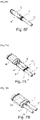
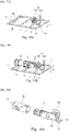
- Step 1/ A central contact 2 is preassembled. To do this, a part forming a socket 21 with petals, made of electrically conductive material, is fitted and crimped in a cylindrical body 20, electrically conductive ( Figures 2A, 2B ). The crimping operation can be replaced by a snapping operation.
- the sleeve 21 is extended at the rear by a generally U-shaped crimping part comprising a receiving barrel 22 and two crimping fins 23 connected to the barrel 22, preferably being symmetrical on either side of the barrel.
- Step 2/ The pre-assembled central contact 2 is then fitted and fixed in an electrical insulating part 3. More precisely, this assembly is made so as to have the cylindrical body 20 completely housed and fixed inside a cylindrical body 30 electrical insulator and the crimping part 22, 23 which protrudes at the rear of the insulating body 30, delimited by a cylindrical support portion 31, as detailed below ( figures 2C, 2D ).
- Step 3/ A one-piece metal blank 5 is provided for assembly by crimping ( figure 2E ).
- the assembly can also be carried out by a force fitting or clipping or overmolding technique, as detailed below.
- This metal blank is produced by a cut-out technique, preferably rolled from a continuous strip.
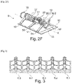
- This one-piece blank 5 firstly comprises a peripheral strip 50 forming a perforated support which extends along a longitudinal axis X and which has in the example illustrated overall the shape of a rectangular frame.
- Two respectively front and rear crimping parts 51, 52 each extend along the longitudinal axis X while being separated from each other, and are held to the support 50 by at least one blade 53, 54 forming a attached. These fasteners can also be found along the longitudinal axis X.
- two lateral fasteners 53, 54 are provided which extend on either side of each of the crimping parts 51, 52. These side fasteners 53, 54 have the function of holding the crimping parts 51, 52 once the connector sub-assembly has been produced.
- the front crimping part 51 comprising a receiving barrel 56 and at least one crimping fin 57 connected to the barrel 56 and intended to receive and to be crimped around the electrical insulating part 3 housing the preassembled central contact 2.
- the rear crimping part 52 comprising a receiving barrel 58 and at least one crimping fin 59 connected to the barrel 58 adapted to be crimped around the shielding braid 12 of the insulated cable 1.
- the rear crimping part also comprises at least one crimping fin 59.2 adapted to be crimped around a seal 7. In the case where sealing is not required, the seal is not necessary and the crimping fin is directly crimped around the outer sheath of the cable.
- the rear crimping part 52 is continuous to guarantee electrical ground continuity.
- the one-piece blank 5 further comprises a support blade 55, connected to the support 50 and which extends inside the latter between the two crimping parts 51, 52 so as to form a support zone for the electrical insulating part 3.
- the support strip 55 is continuous from one longitudinal edge to the other of the support 50.
- the central portion of the support strip 55 is shaped as a cylinder portion complementary to the support portion 31. It can be in the form of a blade, one end of which is connected to a longitudinal edge of the support 50 and the free end serves as a support for the portion 31 of the electrical insulator 3.
- the arrangement of the front and rear crimping parts 51, 52, of the various fasteners 53, 54 and of the support blade 55 relative to the preferably flat support 50 defines empty spaces (V) or openings between and around the parts of crimping. These empty spaces (V) make it possible to pass crimping jaws dimensioned to be robust, and therefore to crimp cables 1 of large section, in particular power cables.
- Step 4/ Position the electrical insulator 3 in the front crimping part 51 of the blank 5 ( figure 2E ). More precisely, the positioning is carried out so that the body 30 of the insulator 3 comes to marry the crimping barrel 56 and the cylindrical portion 31 comes to bear against the support blade 55.
- the crimping fins 57 are then folded around the cylindrical body 30.
- the electrical insulator 3 is then crimped in the one-piece blank 5, which forms a connector sub-assembly 6 intended for assembly by crimping with a cable 1 ( figure 2F ).
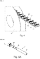
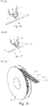
- the continuous strip can take the form of a continuous reel 60 wound around a chuck ( figure 4 ).
- This coil 60 can be made entirely in an assembly unit independent of an assembly unit with a cable 1.
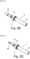
- Step 1/ The outer sheath 11 and the inner sheath 13 are respectively pre-stripped to reveal the conductor(s) 10 and the metal braid 12 over a predetermined length ( figure 5A ).
- Step 2/ A seal 7 is fitted around the outer sheath 11 of the cable 1 ( figure 5B ). According to a variant, this step 2/ can take place before step 1/ to avoid any potential damage to the metal braid.
- Step 3/ Remove the bare part of the inner sheath 13 of the cable 1 ( Fig. 5C ).
- Step 11/ A cable 1 prepared according to the figures 5A to 5C .
- Step ii/ A sub-assembly 6 is supplied from a blank from the reel 60.
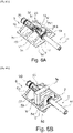
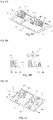
- Step iii1/ The cable 1 is positioned in the sub-assembly 6 so that the stripped part 10 of the conductive wire(s) 1 is housed in the crimping part 22, 23 of the preassembled central contact 2 and that the stripped part of the shielding braid 12 and the seal 7 comes to be housed in the barrel 58 of the rear crimping part 52 of the sub-assembly 6 ( Figure 6A ).
- Step ivl/ The crimping is carried out simultaneously, by means of a tool of the jaw-anvil type (M), inserted into the openings or empty spaces (V) between the support 50 and the fastener(s) 53 , 54 and the support blade(s) 55, on the one hand of the crimping part 22, 23 of the central contact preassembled on the conductive wire(s) 10 and, on the other hand, on the other hand, of the rear crimping part 52 of the sub-assembly on the shielding braid 12 and on the seal 7 ( figure 6B ).
- the robust jaws M simultaneously fold the pair of crimping fins 23 around the conductor(s) 10 and each of the two pairs of crimping fins 59.1 and 59.2 respectively around the metallic shielding braid 12 and gasket seal 7.
- Step v1/ The cutting is then carried out either mechanically by means of a blade or by laser of the fasteners 53, 54 ( Fig. 6C ).
- Step vii/ The central contact 2 is then fitted around the conductive wire(s) 10 in the insulating part 3 to obtain their final assembly by snap-fastening ( figure 6D ).
- Step viil/ A shielding casing 8 is fitted and snapped around both the electrical insulation and the crimped front part 51, so as to obtain a unitary shielded contact 9 ( figures 6E and 6F ).
- the latching is such that the shielding casing 8 is in rear abutment against the front of the seal 7.
- the casing 8 is finally crimped at the level of the crimping of the fins 59.2 and the barrel of the seal 7, which provides electrical continuity between the shielding braid of the cable, the shaft 58 of the support and the shielding casing 8. The shielding efficiency is then guaranteed.
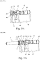
- Step VIII/ the two individual connectors 9.1, 9.2 are mounted in a one-piece connector housing 90 up to their front abutment in the housing ( Figures 7A, 7B ). The contacts are snapped into housing 90.
- Step ix1/ The forces of the cable are taken up and the two unit contacts 9.1, 9.2 are protected by fixing two retention flanges 91, 92 to the rear of the housing 90 of the connector ( Figures 7C, 7D ).
- the front of the 100 two-way connector as it is finally assembled is shown in figure 8 .
- the connector 100 obtained therefore has individualized electromagnetic shielding by unitary contact 9.1, 9.2 and an overall fluid seal at the level of the housing 90.
- the crimping parts 51, 52 are raised relative to the plane of the support frame 50. This allows the cable to be inserted without being hindered by this support frame 50.
- the figures 12A to 12G show the different steps of an alternative method of assembling a two-way connector 100 integrating two wired individual contacts obtained from a subassembly according to the first alternative of the invention.
- Step vii'1/ The mounting of at least one shielding envelope 80 surrounding the rear part 52 is then carried out with the fins 59.1, 59.2, 59.3 crimped ( Figures 12C, 12D ) then that of a shielding envelope 81 surrounding both the electrical insulating part 3 and the crimped front part 51 ( figures 12E , 12F ), so as to obtain a unitary shielded contact 9.
- Stage viii'1/ Two half-shells 93, 94 of the interface box are then mounted around two individual shielded contacts 9.1, 9.2 according to stage vii'1/( figure 12G ).
- the connector 100 obtained according to this alternative mode and represented on the picture 12H therefore has individualized electromagnetic shielding per unitary contact 9.1, 9.2 and also individualized fluid sealing per unitary contact 9.1, 9.2. shielding electromagnetic of this connector can be more efficient than that obtained with individual contacts 9 represented in figure 6F .
- the figure 13 represents an alternative mode of connector 100 from unitary unshielded contacts 9'1, 9'2 like that 9' illustrated in figure 12B , obtained from a subset according to the first alternative of the invention.
- Steps i1/ to v1/ are not described here, which remain identical to those previously described except that the seal 7 is fitted around the inner sheath 13, a pair of crimping fins 59.2 then being folded over beforehand around joint 7 ( figures 12A and 12B ).
- Step vi"1 / The central contact crimped around the conductive wire(s) is fitted into the electrical insulating part (3) to obtain their final assembly and the fins 59.3 are crimped on the insulator 3 to maintain the whole.
- Step vii" 1/ Two shielding half-shells 82, 83 are mounted covering both the electrical insulating part 3 and the crimped front part 51 as well as the crimped fins 59.3, 59.2 and 59.1 ( figure 13 ).
- Stage viii"1/ Two half-shells 93, 94 of the interface box are assembled around the unshielded contacts 9'1, 9'2 according to stage vii"1/.
- two support half-shells 95, 96 can be inserted, each inserted between the two unitary contacts 9'1, 9'2 and a shielding half-shell 82, 83 ( figure 13 ) to withstand and take up the forces which may be exerted on the sub-assemblies 9 .
- the connector 100 obtained according to this other alternative mode therefore has overall electromagnetic shielding for the two unitary contacts 9'1, 9'2 and individualized fluid sealing per unitary contact 9'1, 9'2.
- the figure 14 shows an alternative embodiment of a two-way connector housing.
- Projecting reliefs 930 can be integrated inside the case to support the front of the sub-assembly 9′ typically resting against the crimped fins 57 or shaft 56. These positioning reliefs replace the support half-shells 95, 96.
- One or more metallic reliefs 831 can also be integrated into shields 82 and 83 to ensure electrical continuity with the shield(s) of contact(s) 9'1, 9'2.
- the one-piece metal blank 5 according to the first alternative of the invention is produced by a technique of cutting, preferably rolled from a continuous strip and then assembled by crimping to the subassembly consisting of a central contact 2 preassembled in an electrically insulating part 3, it is also possible to consider other techniques for producing a connector subassembly.
- the fasteners 53 of the front part 51 are each provided at their free end with a flexible hook 531 which snaps into an eyelet 32 projecting from the periphery of the electrical insulating body 30.
- the fasteners 53 of the front part 51 are each provided at their free end with a harpoon 532 which is harpooned in an eyelet 32 projecting from the periphery of the electrical insulating body 30.
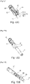
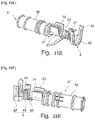
- Step 1/ A central contact 2 is preassembled. To do this, a part forming a socket 21 with petals, made of electrically conductive material, is fitted and crimped in a cylindrical body 20, electrically conductive ( figure 18A , 18B ). The crimping operation can be replaced by a snapping operation.
- the sleeve 21 is extended at the rear by a generally U-shaped front crimping part comprising a receiving barrel 22 and two crimping fins 23 connected to the barrel 22, preferably being symmetrical on either side of the barrel . These crimping fins 23 are intended to receive and to be crimped around the conductor(s) 10 of the cable 1.
- a protrusion of material 24 is provided in the rear extension of the receiving barrel 22. This protrusion of material 24 forms an assembly junction part, as detailed below.
- Step 2/ A metal crimp rear part 4 is provided for assembly with the central contact sub-assembly 2 ( Fig. 18C ).
- This crimping part 4 is made by a cut-out technique, preferably rolled from a continuous strip.
- the material and/or the thickness of this rear crimping part 4 is different from that of the sleeve 21.
- This rear crimping part 4 comprising a receiving barrel 40 and at least one crimping fin 41 connected to the barrel 40 adapted to be crimped around the shield braid 12 of the insulated cable 1.
- the rear crimping part 4 also comprises at least one crimping fin 42 adapted to be crimped around a seal 7. In the case where the seal is not required, the seal is not necessary and the crimping fin 42 is crimped directly around the outer sheath of the cable.
- the rear crimping part 4 is continuous to guarantee electrical ground continuity.
- This rear crimping part 4 further comprises a protrusion of material 43 provided in the front extension of the receiving barrel 40.
- Step 3/ Position the rear crimping part 4 opposite the front crimping part 22, 23 formed in the sleeve 21 ( Fig. 18C ). More precisely, the positioning is carried out so that the two protrusions of material 24, 43 are in contact with each other.
- the assembly can also be carried out by a technique of riveting, clinching, brazing or gluing between the two protrusions 24, 43 to be adapted according to the technique chosen.
- a 2′ subset is obtained here.
- Step 4/ We then fit and fix the central contact 2 of the sub-assembly 2′ preassembled in an electrical insulating part 3 ( figure 18D ) . More specifically, this assembly is made so as to have the cylindrical body 20 completely housed and fixed inside a cylindrical body 30 electrically insulating and the crimping part 22, 23 which projects at the rear of the insulating body 30 , delimited by a cylindrical bearing portion 31, as detailed below ( Figure 18E ).
- This step 4/ of adding an electrical insulating part is optional. It can also occur after stage 1/ or stage 2/.
- a pre-assembled connector sub-assembly 6' is then ready.
- a continuous carrier strip 44 can be produced from a plurality of unitary sub-assemblies 2'1 to 2'5 or 6'1 to 6'5 which are adjacent and therefore mechanically connected to each other by this carrier strip 44 ( figures 19, 20 ).
- the width L which defines the pitch between two adjacent sub-assemblies 6' or 2', can be adjusted as needed. By decreasing it, the density of the sub-assemblies in the coil is increased, that is to say the number of sub-assemblies that the same coil 61 can carry.
- the carrier strip 44 can be arranged outside each unitary sub-assembly 6' and secured to the rear crimping part 4.
- a pilot hole 45 is drilled directly opposite the barrel 40.
- Additional holes 45 may be drilled at other locations in carrier strip 44 ( figure 22 ).
- the continuous strip can take the form of a continuous reel 61 wound around a mandrel ( figure 23 ).
- This coil 61 can be made entirely in an assembly unit independent of an assembly unit with a cable 1.
- Step 1/ A seal 7 is fitted around the outer sheath 11 of the cable 1 ( figure 24A ) to avoid any potential damage to the metal braid 12, the conductor(s) 10 or the seal 7 itself.
- Step 2/ The outer sheath 11, the inner sheath 13 are respectively pre-stripped to reveal the conductor(s) 10 and the metal braid 12 over a predetermined length ( figure 24B ).
- step 2/ can be performed before step 1/.
- Step 3/ Remove the bare part of the inner sheath 13 of the cable 1 ( figure 24C ).
- Step i2/ A cable 1 prepared according to the figures 24A to 24C .
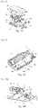
- Step ii2/ A pre-assembled sub-assembly 2' or 6' secured to the coil 61 is provided by the carrier strip 44 which is placed on a crimping support S.
- the crimping support S supports at least the barrel 22 and 40 of the front and rear crimping parts and preferably also the cylindrical body 30 electrically insulating ( figure 25A ).
- This crimping support S advantageously has cylindrical portions which hug the barrels 22, 40 of the front and rear crimping parts respectively of the preassembled sub-assembly 2' or 5.
- a mechanical cutting tool D for the carrier strip 44 is positioned around the latter ( figure 25A ).
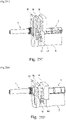
- Step iii2/ The cable 1 provided with the seal 7 is positioned in the sub-assembly 2′ or 6′ so that the stripped part 10 of the conductive wire(s) 1 comes to be housed in the front part crimping 22, 23 of the pre-assembled central contact 2' or 6' and that the stripped part of the shielding braid 12 and the seal 7 come to be housed in the barrel 40 of the rear crimping part 4 of the sub-assembly 2' or 6' ( figure 25B ).
- Step iii′2/ The jaws M are brought as close as possible, preferably in contact with the crimping fins 23, 41, 42, in order to avoid their rotation when cutting the carrier strip. Then the carrying strip 44 is cut, which is obtained by shearing by lowering the cutting tool D (arrow of the figure 25C ), once the cable has been positioned.
- Step iv2/ The crimping is then carried out, by means of a tool of the crimping jaw-support type (M/S), on the one hand of the front crimping part 22, 23 of the central contact preassembled on the ) wire(s) conductor(s) 10 and, on the other hand, of the rear part of crimping 4 of the sub-assembly on the shielding braid 12 and on the seal 7 ( figure 25D ).
- M/S crimping jaw-support type
- the jaws M simultaneously fold the pair of crimping fins 23 around the conductor(s) 10 and each of the two pairs of crimping fins 41 and 42 respectively around the metallic shielding braid 12 and the seal 7.
- the crimping jaws M are advantageously sized to be robust, and therefore crimp cables 1 of large section, in particular power cables.
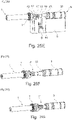
- Step v2/ To finalize the wired unitary contact 9', the electrical insulating part 3 is pushed into its final position of use ( Figure 25G ).
- Step vi2/ The mounting of at least one shielding envelope 8 surrounding both the electrical insulating part 3 and the crimped parts is then carried out, so as to obtain a unitary shielded contact 9 ( figures 25H ).
- the central contact 2 is of the female type and is made from two separate parts 20 and 21. It is possible to envisage making a central contact of the male type and a central contact in a single piece.
Landscapes
- Engineering & Computer Science (AREA)
- Manufacturing & Machinery (AREA)
- Details Of Connecting Devices For Male And Female Coupling (AREA)
- Multi-Conductor Connections (AREA)
- Manufacturing Of Electrical Connectors (AREA)
Applications Claiming Priority (2)
| Application Number | Priority Date | Filing Date | Title |
|---|---|---|---|
| FR2101584A FR3119945A1 (fr) | 2021-02-18 | 2021-02-18 | Ebauche monobloc métallique d’assemblage par sertissage d’un connecteur à un câble isolé, sous-ensemble de connecteur préassemblé intégrant l’ébauche, procédé d’assemblage d’un connecteur à un câble associés. |
| FR2111228A FR3128571A1 (fr) | 2021-10-22 | 2021-10-22 | Sous-ensemble préassemblé de connecteur comprenant un contact central et deux parties de sertissage de matière et/ou épaisseur différente(s), bobine de sous-ensembles et procédé d’assemblage d’un connecteur à un câble associés. |
Publications (2)
| Publication Number | Publication Date |
|---|---|
| EP4087069A2 true EP4087069A2 (de) | 2022-11-09 |
| EP4087069A3 EP4087069A3 (de) | 2022-12-28 |
Family
ID=80168322
Family Applications (1)
| Application Number | Title | Priority Date | Filing Date |
|---|---|---|---|
| EP22156115.2A Pending EP4087069A3 (de) | 2021-02-18 | 2022-02-10 | Einteiliger metallischer rohling zur crimpverbindung eines verbinders mit einem isolierten kabel, vormontierte verbinderuntereinheit, die den rohling oder einen zentralen kontakt und zwei crimpteile aus unterschiedlichem material und/oder unterschiedlicher dicke umfasst, entsprechende verfahren zur montage eines verbinders an ein kabel |
Country Status (3)
| Country | Link |
|---|---|
| US (1) | US12184020B2 (de) |
| EP (1) | EP4087069A3 (de) |
| CN (1) | CN115020996A (de) |
Families Citing this family (1)
| Publication number | Priority date | Publication date | Assignee | Title |
|---|---|---|---|---|
| EP4664685A1 (de) * | 2024-06-11 | 2025-12-17 | Aptiv Technologies AG | Kreuzbarer brückenkontakt für ein hochgeschwindigkeits-doppelaxialreparaturkit |
Family Cites Families (30)
| Publication number | Priority date | Publication date | Assignee | Title |
|---|---|---|---|---|
| US3163485A (en) * | 1960-12-08 | 1964-12-29 | Amp Inc | Connector pins |
| DE3023232A1 (de) * | 1980-06-21 | 1982-01-14 | Harting Elektronik Gmbh, 4992 Espelkamp | Elektrisches kontaktelement und verfahren zur herstellung eines derartigen kontaktelementes |
| JP2899933B2 (ja) * | 1993-03-24 | 1999-06-02 | 日本航空電子工業株式会社 | ケーブル接続コンタクト及びその製造方法、ケーブル接続コンタクトを用いたコネクタ装置 |
| JP3207093B2 (ja) * | 1995-11-02 | 2001-09-10 | 矢崎総業株式会社 | コネクタ用接触端子部材 |
| JP3631913B2 (ja) * | 1999-02-05 | 2005-03-23 | 矢崎総業株式会社 | シールド端子及び該シールド端子の製造方法 |
| US6848941B2 (en) * | 2003-02-13 | 2005-02-01 | Andrew Corporation | Low cost, high performance cable-connector system and assembly method |
| JP4096190B2 (ja) * | 2003-09-16 | 2008-06-04 | 矢崎総業株式会社 | 同軸ケーブル用シールド端子 |
| JP2005317298A (ja) * | 2004-04-28 | 2005-11-10 | Hirose Electric Co Ltd | 同軸ケーブル用端子と、この同軸ケーブル用端子の取付構造及び取付方法 |
| JP2006004820A (ja) * | 2004-06-18 | 2006-01-05 | Yazaki Corp | 同軸ケーブル用シールド端子 |
| CN100466401C (zh) * | 2006-07-20 | 2009-03-04 | 宣德科技股份有限公司 | 射频连接器的制造方法 |
| US7252559B1 (en) * | 2006-10-13 | 2007-08-07 | Delphi Technologies, Inc. | Two piece electrical terminal |
| US8011954B2 (en) * | 2007-05-29 | 2011-09-06 | Autonetworks Technologies, Ltd. | Shielded connector |
| JP2009004147A (ja) * | 2007-06-20 | 2009-01-08 | Yazaki Corp | コンデンサ内蔵同軸コネクタ |
| JP4926890B2 (ja) * | 2007-08-28 | 2012-05-09 | 矢崎総業株式会社 | 同軸ケーブルの端末処理構造 |
| JP5244427B2 (ja) * | 2008-03-13 | 2013-07-24 | 矢崎総業株式会社 | 電子部品実装・絶縁体一体型内導体端子、及び同軸コネクタ |
| JP2009224079A (ja) * | 2008-03-14 | 2009-10-01 | Yazaki Corp | 内導体端子、連鎖端子、及び、同軸ケーブルと内導体端子との圧着接続方法 |
| US7909645B2 (en) * | 2008-06-24 | 2011-03-22 | Tyco Electronics Corporation | Coaxial cable connector housing |
| JP5195230B2 (ja) * | 2008-09-26 | 2013-05-08 | 住友電装株式会社 | 端子金具付き電線 |
| JP5336963B2 (ja) * | 2009-07-22 | 2013-11-06 | 日本航空電子工業株式会社 | コネクタ |
| JP5586354B2 (ja) * | 2010-07-15 | 2014-09-10 | 矢崎総業株式会社 | 金型及び圧着方法 |
| FR2970604B1 (fr) * | 2011-01-18 | 2017-10-20 | Peugeot Citroen Automobiles Sa | Connecteur pour cable electrique blinde de vehicule |
| JP5922442B2 (ja) * | 2012-02-29 | 2016-05-24 | 矢崎総業株式会社 | 同軸コネクタ |
| US9153878B2 (en) * | 2013-10-29 | 2015-10-06 | Delphi Technologies, Inc. | Termination assembly for a shielded cable and method of assembling |
| TWI571014B (zh) * | 2014-12-19 | 2017-02-11 | 宣德科技股份有限公司 | 射頻連接器的製造方法 |
| CN105790030A (zh) * | 2014-12-22 | 2016-07-20 | 宣德科技股份有限公司 | 射频连接器的制造方法 |
| US9941607B2 (en) * | 2015-10-29 | 2018-04-10 | Hirose Electric Co., Ltd. | Coaxial cable connector, carrier-equipped coaxial cable connector, and method for manufacturing coaxial cable connector |
| WO2017144070A1 (de) * | 2016-02-26 | 2017-08-31 | Rosenberger Hochfrequenztechnik Gmbh & Co. Kg | Aussenleiteranordnung für einen koaxial-steckverbinder |
| TWI608678B (zh) * | 2016-07-01 | 2017-12-11 | 春源科技(深圳)有限公司 | Rf線端連接器與同軸線纜的連接方法及其使用的內部端子 |
| CN109921200A (zh) * | 2017-12-12 | 2019-06-21 | 泰科电子(上海)有限公司 | 端子及其制造方法和通过该端子电连接导线和多个电缆的方法 |
| JP2019216043A (ja) * | 2018-06-13 | 2019-12-19 | 矢崎総業株式会社 | 内導体端子、及び、内導体端子を用いた同軸線用の端子ユニット |
-
2022
- 2022-02-10 EP EP22156115.2A patent/EP4087069A3/de active Pending
- 2022-02-17 US US17/651,463 patent/US12184020B2/en active Active
- 2022-02-18 CN CN202210152761.3A patent/CN115020996A/zh active Pending
Also Published As
| Publication number | Publication date |
|---|---|
| EP4087069A3 (de) | 2022-12-28 |
| US12184020B2 (en) | 2024-12-31 |
| CN115020996A (zh) | 2022-09-06 |
| US20220263254A1 (en) | 2022-08-18 |
Similar Documents
| Publication | Publication Date | Title |
|---|---|---|
| EP3496213B1 (de) | Impedanzanpassungsteil für steckverbinder, der auf einem kabel mit isolierten elektrischen drähten montiert ist | |
| EP3164910B1 (de) | Montagesockel für verdrahtetes elektrisches bauelement, entsprechendes beleuchtungsmodul, verfahren zur herstellung eines zugehörigen moduls und entsprechendes kleidungsstück | |
| FR3071112A1 (fr) | Systeme de connexion pour machine electrique. | |
| FR3074614A1 (fr) | Connecteur pour cable a fils electriques isoles, comprenant un corps logeant des contacts centraux en saillie et deux demi-coques assemblees entre elles autour du corps et des contacts sertis sur les fils | |
| FR2719166A1 (fr) | Adaptateur pour un connecteur multibroche & connecteur multibroche correspondant. | |
| EP4087069A2 (de) | Einteiliger metallischer rohling zur crimpverbindung eines verbinders mit einem isolierten kabel, vormontierte verbinderuntereinheit, die den rohling oder einen zentralen kontakt und zwei crimpteile aus unterschiedlichem material und/oder unterschiedlicher dicke umfasst, entsprechende verfahren zur montage eines verbinders an ein kabel | |
| EP3477789B1 (de) | Adapter für abgeschirmten steckverbinder, abgeschirmter steckverbinder und montageverfahren eines solchen abgeschirmten steckverbinders | |
| FR3119945A1 (fr) | Ebauche monobloc métallique d’assemblage par sertissage d’un connecteur à un câble isolé, sous-ensemble de connecteur préassemblé intégrant l’ébauche, procédé d’assemblage d’un connecteur à un câble associés. | |
| FR3028677A1 (fr) | Assemblage d'un ensemble de raccordement electrique | |
| FR2582872A1 (fr) | Plaque porte-balais perfectionnee pour moteur electrique et son procede de fabrication | |
| EP3560043B1 (de) | Elektrische anordnung für ein kraftfahrzeug mit einem koaxialkabel und elektrische anschlussklemme | |
| FR2956780A1 (fr) | Ensemble de contacts electriques a sertir, procede de conditionnement, procede de sertissage et pince de sertissage correspondants | |
| FR3062000B1 (fr) | Isolant rigide pour bobinage de rotor de moteur electrique | |
| EP2135326A1 (de) | Leitfähige vorrichtung für den elektrischen kontakt einer leiterabschirmungsummantelung | |
| FR3128571A1 (fr) | Sous-ensemble préassemblé de connecteur comprenant un contact central et deux parties de sertissage de matière et/ou épaisseur différente(s), bobine de sous-ensembles et procédé d’assemblage d’un connecteur à un câble associés. | |
| EP3349305B1 (de) | Verbessertes elektrisches anschlusskit | |
| WO2020174166A1 (fr) | Dispositif de connexion pour stator | |
| EP2850697B1 (de) | Verbinder für abgeschirmtes stromkabel und entsprechendes montageverfahren | |
| EP1085553A1 (de) | Serien Herstellungsverfahren von Sicherungshaltermodule und Sicherungshaltermodule hergestellt mit diesem Verfahren | |
| EP3109948B1 (de) | Herstellungsverfahren eines elektrischen kontakts, und elektrischer kontakt | |
| EP3758166B1 (de) | Elektrische verbindungsvorrichtung | |
| FR3000619A1 (fr) | Organe de raccordement de conducteurs sur une borne unique | |
| EP0268502B1 (de) | Klammerförmiges Kabelendstück für Zündverteilerdeckel | |
| EP3312948B1 (de) | Elektrische steckdose, die ein monoblockteil zur halterung und aufnahme von höckereinsätzen umfasst, und verfahren zum zusammenbau einer solchen elektrischen steckdose | |
| FR2981215A1 (fr) | Raccordement de deux conducteurs electriques comportant notamment deux ames en metaux differents |
Legal Events
| Date | Code | Title | Description |
|---|---|---|---|
| PUAI | Public reference made under article 153(3) epc to a published international application that has entered the european phase |
Free format text: ORIGINAL CODE: 0009012 |
|
| STAA | Information on the status of an ep patent application or granted ep patent |
Free format text: STATUS: REQUEST FOR EXAMINATION WAS MADE |
|
| 17P | Request for examination filed |
Effective date: 20220210 |
|
| AK | Designated contracting states |
Kind code of ref document: A2 Designated state(s): AL AT BE BG CH CY CZ DE DK EE ES FI FR GB GR HR HU IE IS IT LI LT LU LV MC MK MT NL NO PL PT RO RS SE SI SK SM TR |
|
| PUAL | Search report despatched |
Free format text: ORIGINAL CODE: 0009013 |
|
| AK | Designated contracting states |
Kind code of ref document: A3 Designated state(s): AL AT BE BG CH CY CZ DE DK EE ES FI FR GB GR HR HU IE IS IT LI LT LU LV MC MK MT NL NO PL PT RO RS SE SI SK SM TR |
|
| RIC1 | Information provided on ipc code assigned before grant |
Ipc: H01R 24/40 20110101ALN20221122BHEP Ipc: H01R 13/52 20060101ALN20221122BHEP Ipc: H01R 9/05 20060101ALI20221122BHEP Ipc: H01R 4/18 20060101ALI20221122BHEP Ipc: H01R 43/16 20060101ALI20221122BHEP Ipc: H01R 43/055 20060101ALI20221122BHEP Ipc: H01R 43/048 20060101AFI20221122BHEP |
|
| STAA | Information on the status of an ep patent application or granted ep patent |
Free format text: STATUS: EXAMINATION IS IN PROGRESS |
|
| 17Q | First examination report despatched |
Effective date: 20250401 |