EP4087076A1 - Procédé autonome pour empêcher la baisse de tension de modules électroniques sous-marins - Google Patents
Procédé autonome pour empêcher la baisse de tension de modules électroniques sous-marins Download PDFInfo
- Publication number
- EP4087076A1 EP4087076A1 EP21172005.7A EP21172005A EP4087076A1 EP 4087076 A1 EP4087076 A1 EP 4087076A1 EP 21172005 A EP21172005 A EP 21172005A EP 4087076 A1 EP4087076 A1 EP 4087076A1
- Authority
- EP
- European Patent Office
- Prior art keywords
- subsea
- electronic module
- slave
- voltage
- threshold value
- Prior art date
- Legal status (The legal status is an assumption and is not a legal conclusion. Google has not performed a legal analysis and makes no representation as to the accuracy of the status listed.)
- Pending
Links
Images


Classifications
-
- H—ELECTRICITY
- H02—GENERATION; CONVERSION OR DISTRIBUTION OF ELECTRIC POWER
- H02H—EMERGENCY PROTECTIVE CIRCUIT ARRANGEMENTS
- H02H3/00—Emergency protective circuit arrangements for automatic disconnection directly responsive to an undesired change from normal electric working condition with or without subsequent reconnection ; integrated protection
- H02H3/02—Details
- H02H3/04—Details with warning or supervision in addition to disconnection, e.g. for indicating that protective apparatus has functioned
-
- H—ELECTRICITY
- H02—GENERATION; CONVERSION OR DISTRIBUTION OF ELECTRIC POWER
- H02H—EMERGENCY PROTECTIVE CIRCUIT ARRANGEMENTS
- H02H3/00—Emergency protective circuit arrangements for automatic disconnection directly responsive to an undesired change from normal electric working condition with or without subsequent reconnection ; integrated protection
- H02H3/02—Details
- H02H3/06—Details with automatic reconnection
-
- E—FIXED CONSTRUCTIONS
- E21—EARTH OR ROCK DRILLING; MINING
- E21B—EARTH OR ROCK DRILLING; OBTAINING OIL, GAS, WATER, SOLUBLE OR MELTABLE MATERIALS OR A SLURRY OF MINERALS FROM WELLS
- E21B33/00—Sealing or packing boreholes or wells
- E21B33/02—Surface sealing or packing
- E21B33/03—Well heads; Setting-up thereof
- E21B33/035—Well heads; Setting-up thereof specially adapted for underwater installations
- E21B33/0355—Control systems, e.g. hydraulic, pneumatic, electric, acoustic, for submerged well heads
-
- E—FIXED CONSTRUCTIONS
- E21—EARTH OR ROCK DRILLING; MINING
- E21B—EARTH OR ROCK DRILLING; OBTAINING OIL, GAS, WATER, SOLUBLE OR MELTABLE MATERIALS OR A SLURRY OF MINERALS FROM WELLS
- E21B41/00—Equipment or details not covered by groups E21B15/00 - E21B40/00
- E21B41/0007—Equipment or details not covered by groups E21B15/00 - E21B40/00 for underwater installations
-
- H—ELECTRICITY
- H02—GENERATION; CONVERSION OR DISTRIBUTION OF ELECTRIC POWER
- H02J—ELECTRIC POWER NETWORKS; CIRCUIT ARRANGEMENTS OR SYSTEMS FOR SUPPLYING OR DISTRIBUTING ELECTRIC POWER; SYSTEMS FOR STORING ELECTRIC ENERGY
- H02J3/00—Circuit arrangements for AC mains or AC distribution networks
- H02J3/12—Arrangements for adjusting voltage in AC networks by changing a characteristic of the network load
- H02J3/14—Arrangements for adjusting voltage in AC networks by changing a characteristic of the network load by switching loads on to, or off from, the networks, e.g. progressively balanced loading
-
- H—ELECTRICITY
- H02—GENERATION; CONVERSION OR DISTRIBUTION OF ELECTRIC POWER
- H02H—EMERGENCY PROTECTIVE CIRCUIT ARRANGEMENTS
- H02H3/00—Emergency protective circuit arrangements for automatic disconnection directly responsive to an undesired change from normal electric working condition with or without subsequent reconnection ; integrated protection
- H02H3/46—Emergency protective circuit arrangements for automatic disconnection directly responsive to an undesired change from normal electric working condition with or without subsequent reconnection ; integrated protection responsive to frequency deviations
-
- H—ELECTRICITY
- H02—GENERATION; CONVERSION OR DISTRIBUTION OF ELECTRIC POWER
- H02J—ELECTRIC POWER NETWORKS; CIRCUIT ARRANGEMENTS OR SYSTEMS FOR SUPPLYING OR DISTRIBUTING ELECTRIC POWER; SYSTEMS FOR STORING ELECTRIC ENERGY
- H02J2105/00—Networks for supplying or distributing electric power characterised by their spatial reach or by the load
- H02J2105/30—Networks for supplying or distributing electric power characterised by their spatial reach or by the load the load networks being external to vehicles, i.e. exchanging power with vehicles
- H02J2105/31—Networks for supplying or distributing electric power characterised by their spatial reach or by the load the load networks being external to vehicles, i.e. exchanging power with vehicles for ships or vessels
Definitions
- the present invention relates to a method for preventing a brownout of a subsea system comprising one or more subsea devices each comprising a subsea electronic module.
- the state-of-the-art of subsea production systems include, for instance, subsea valve actuators (SVA) with an all-electric interface.
- SVA subsea valve actuators
- SEM master subsea electronic module
- the operator sends high-level commands, which are relayed through the master SEM to a slave SEM embedded in the actuator itself.
- the slave SEM proceeds to translate these high-level commands into a sequence of low-level operations.
- these low-level operations may include for example: controlling electric motor drivers; switching directional control valves; switching electromechanical latches; measuring process variables (position, torque, etc%) via sensors; recharging internal battery packs; switching internal power supply of electric peripheral devices, etc.
- these operations may also be executed autonomously, without a prompt from the operator.
- the actuators may be powered with an instrumentation electric supply, as defined by the SIIS standard.
- an instrumentation electric supply as defined by the SIIS standard.
- multiple actuators are normally connected in a star topology in a similar fashion as shown in Figure 1 . This array reduces the amount of subsea cables and connectors required to interface the actuators with the SEM.
- the operator may command - accidentally or unknowingly - the actuators to activate simultaneously, drawing more electric power from the power supply than it is available. This may then cause a brownout, dropping the supplied electric voltage to all actuators in the network. If this happens, the actuators may unexpectedly shutdown, causing an unwanted disruption in the production.
- One way to prevent this is to use the SEM as a centralized observer, to monitor actively all actuators in the network and to relay the commands selectively according to the current power available in the network. This requires a highly customizable application on the SEM, which must be configured ad hoc, according to the topology and the types of the actuators in the network.
- a less complex alternative can be partially shift the responsibility to the operator to act on-the-fly, while ensuring the actuators never overload the available power supply without any feedback from the actuator.
- scope of the present invention is to provide a method to prevent brownout, which overcomes the mentioned drawbacks.
- the present invention is based on the idea of an embedded system that constantly monitors the voltage supply of the slave electronic modules.
- a method for controlling a subsea system so as to prevent brownout of the subsea system comprises at least one slave subsea electronic module installed in a subsea device, wherein said subsea system (100) further comprises a master subsea electronic module, which is configured to provide power to the at least one slave subsea electronic module, wherein said subsea device is configured to execute a plurality of operations.
- the method comprising the following steps:
- a method for controlling a slave subsea electronic module is provided.
- the slave subsea electronic module is installed in a subsea actuator.
- this is just an example and that the invention can be applied to many different types of subsea devices containing a slave subsea electronic module.
- the actuators are connected in a star topology or in a bus topology.
- this invention can also work with a single actuator and it is not necessary to provide more actuators.
- the subsea system 100 comprises a master subsea electronic module 10 to which a plurality of subsea valve actuators 20 are connected.
- the master subsea electronic module 10 is configured to provide power and communication relayed from an operator on the topside to the subsea valve actuators 20 at an electrical interface of each actuators 20.
- Each of the actuators is provided with a slave subsea electronic module 22, which is embedded in the actuator itself.
- the slave subsea electronic module is configured to translate high-level commands into a sequence of low-level operations.
- these low-level operations may include: controlling electric motor drivers; frequency inverters; switching directional control valves; switching electromechanical latches and relays; measuring process variables (position, torque, etc%) via electronic sensors; recharging internal battery packs and switching internal power supply of electric peripheral devices.
- these operations may also be executed autonomously, without a prompt from the operator.
- the invention comprises an embedded system installed in each of the actuators (or any subsea device with a slave subsea electronic module) that constantly monitors the voltage supply (or alternative the current) of each of the device.
- the voltage supply measurement can be adequately conditioned, for example filtered in order to eliminate fluctuations or ripples, which are not caused by a brownout.
- the filter can be represented by a standard filter known from the state of the art or can be represented by a filter integrated in a software used in the actuator.
- a certain threshold value the method considers that brownout is started. Therefore, the system then interrupts its present actions and initiates a sequence to power off or to reduce the power consumption of the electric components in the device.
- the aim is to prevent the brownout from shutting down the slave subsea electronic module and potentially the valve actuator or the subsea device as well.
- the threshold value is a value for the voltage that is lower than the nominal but still sufficient to provide power to the device and its peripherals.
- the same method can be applied by measuring the current drawn from the device and to judge if a threshold value (maximum current threshold) for the current has been reached: in that case, the system interrupts its present actions and initiates a sequence to power off or to reduce the power consumption of the electric components in the device.
- a threshold value maximum current threshold
- the order of electric components that are de-energized is prioritized in a manner to have the minimum impact possible on the actual operational state of the device.
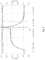
- An example of the voltage/current profile and the signal that trips this system is shown in Figure 2 .
- a trip signal is provided by the actuator or device, and particularly by the slave subsea electronic module inside the device, which causes some of the operations provided by the device to stop.
- a ripple threshold which in this case is a value between 20 and 25 V
- a ripple threshold which in ths case is a value comprised between 4 and 5 A
- Figure 3 shows in detail an example of how such a process is executed in each of the actuators 20 of figure 1 .
- step 1 the voltage received at the interface of the actuator 20 is monitored by the slave subsea electronic module 22 and in step 2 it is controlled if the measured voltage (which has been preferably adequately conditioned before) is lower or higher with respect to the ripple threshold. If the voltage is higher 2a than the ripple threshold, the voltage is measured again.
- At least one present action of the actuator has to be interrupted 3 in order to prevent brownout from occurring.
- a list of low level operations is provided to each actuator with a predetermined priority.
- the first operation that is controlled is if the electric drive is active
- the third operation that is controlled is if the condition monitoring is active
- the fourth operation that is controlled is if the safety valves are active.
- the first operation that is controlled is the one with lower priority and the last one is the one with the highest priority, since, as will be clearly explained in the prosecution of the description, it is the last action that it will be shut down.
- step 41 the electric drive is powered off and the logic returns to step 1 and the voltage is monitored again.
- step 4 If the voltage is still lower than the ripple threshold or if in step 4 it has been judged that the electric drive was inactive, the logic prosecute to step 5 where it is evaluated if the line relief valves are active.
- the steps are analogous to the ones described for the step 4: if the line relief valves are active, the line relief valves are powered off 51 and the logic returns to step 1.
- step 6 If the voltage is still lower than the ripple threshold or if in step 5 it has been judged that the line relief valves were inactive, the logic prosecute to step 6 where it is evaluated if the condition monitoring is active.
- the steps are analogous to the ones described for the steps 4 and 5: if the condition monitoring is active, the condition monitoring is powered off 61 and the logic returns to step 1.
- step 7 If the voltage is still lower than the ripple threshold or if in step 6 it has been judged that the condition monitoring was inactive, the logic prosecute to step 7 where it is evaluated if the safety valves are active.
- the steps are analogous to the ones described for the steps 4, 5 and 6: if the safety valves are active, the safety valves are powered off 71 and the logic goes to step 1, where it is checked again if the voltage is still lower than the ripple threshold.
- step 8 If the voltage is still lower than the ripple threshold or if in step 7 it has been judged that the line safety valves were inactive, the logic prosecute to step 8, where it is detected by the actuator that all the systems of the actuator are off.
- a notification of brownout detection is delivered to an operator.
- the operator can be informed that a brownout has been effectively prevented if after any of the steps 41, 51, 61 or 71 it has been detected that the pressure is higher that the ripple threshold.
- This system must execute these actions faster than the dynamic response of the power supply requires reaching the low voltage supply limit. This period will depend of the power supply characteristics and the electrical current being drawn. However, it depends also on the voltage monitoring system and the processing speed of the logic unit.
- the invention is comprised of a programmable logic unit that controls the electric peripherals in the actuator and a power supply monitoring system able to monitor the instantaneous supply voltage and the instantaneous electrical current consumption.
- the invention includes a logic sequence that dictates the order of deactivation of the electric components in the actuator.
Landscapes
- Engineering & Computer Science (AREA)
- Geology (AREA)
- Life Sciences & Earth Sciences (AREA)
- Mining & Mineral Resources (AREA)
- Power Engineering (AREA)
- Fluid Mechanics (AREA)
- Environmental & Geological Engineering (AREA)
- General Life Sciences & Earth Sciences (AREA)
- Geochemistry & Mineralogy (AREA)
- Physics & Mathematics (AREA)
- Control Of Electric Motors In General (AREA)
- Safety Devices In Control Systems (AREA)
- Direct Current Feeding And Distribution (AREA)
Priority Applications (5)
| Application Number | Priority Date | Filing Date | Title |
|---|---|---|---|
| EP21172005.7A EP4087076A1 (fr) | 2021-05-04 | 2021-05-04 | Procédé autonome pour empêcher la baisse de tension de modules électroniques sous-marins |
| US18/556,907 US12512657B2 (en) | 2021-05-04 | 2022-04-25 | Autonomous method to prevent brownout of subsea electronic modules |
| PCT/EP2022/060798 WO2022233613A1 (fr) | 2021-05-04 | 2022-04-25 | Procédé autonome permettant d'empêcher la baisse de tension de modules électroniques sous-marins |
| BR112023022627A BR112023022627A2 (pt) | 2021-05-04 | 2022-04-25 | Método autônomo para evitar apagão de módulos eletrônicos submarinos |
| CN202280032960.9A CN117242661A (zh) | 2021-05-04 | 2022-04-25 | 防止海底电子模块掉电的自主方法 |
Applications Claiming Priority (1)
| Application Number | Priority Date | Filing Date | Title |
|---|---|---|---|
| EP21172005.7A EP4087076A1 (fr) | 2021-05-04 | 2021-05-04 | Procédé autonome pour empêcher la baisse de tension de modules électroniques sous-marins |
Publications (1)
| Publication Number | Publication Date |
|---|---|
| EP4087076A1 true EP4087076A1 (fr) | 2022-11-09 |
Family
ID=75825423
Family Applications (1)
| Application Number | Title | Priority Date | Filing Date |
|---|---|---|---|
| EP21172005.7A Pending EP4087076A1 (fr) | 2021-05-04 | 2021-05-04 | Procédé autonome pour empêcher la baisse de tension de modules électroniques sous-marins |
Country Status (5)
| Country | Link |
|---|---|
| US (1) | US12512657B2 (fr) |
| EP (1) | EP4087076A1 (fr) |
| CN (1) | CN117242661A (fr) |
| BR (1) | BR112023022627A2 (fr) |
| WO (1) | WO2022233613A1 (fr) |
Cited By (1)
| Publication number | Priority date | Publication date | Assignee | Title |
|---|---|---|---|---|
| WO2024147786A1 (fr) * | 2023-01-04 | 2024-07-11 | Siemens Energy AS | Dispositif de commutation sous-marin |
Families Citing this family (1)
| Publication number | Priority date | Publication date | Assignee | Title |
|---|---|---|---|---|
| GB2632270B (en) * | 2023-07-28 | 2025-07-23 | Baker Hughes Energy Technology UK Ltd | A network and network processing |
Citations (4)
| Publication number | Priority date | Publication date | Assignee | Title |
|---|---|---|---|---|
| US20100244563A1 (en) * | 2009-03-27 | 2010-09-30 | Aclara Power-Line Systems Inc. | Under frequency/under voltage detection in a demand response unit |
| US20110247825A1 (en) * | 2010-04-08 | 2011-10-13 | Framo Engineering As | System and method for subsea power distribution network |
| US20150123464A1 (en) * | 2013-02-28 | 2015-05-07 | Bae Systems Information And Electronic Systems Integration Inc. | Seat power systems and methods |
| US20190319457A1 (en) * | 2016-06-27 | 2019-10-17 | Abb Schweiz Ag | A subsea electric power distribution installation |
Family Cites Families (2)
| Publication number | Priority date | Publication date | Assignee | Title |
|---|---|---|---|---|
| US20150036256A1 (en) * | 2010-07-30 | 2015-02-05 | Exxon Mobil Upstream Research Company | Method for Design of Subsea Electrical Substation and Power Distribution System |
| BR112013030665B1 (pt) * | 2011-06-01 | 2021-01-19 | Total Sa | instalação submarina para distribuição de energia para equipamento submarino e arquitetura elétrica |
-
2021
- 2021-05-04 EP EP21172005.7A patent/EP4087076A1/fr active Pending
-
2022
- 2022-04-25 BR BR112023022627A patent/BR112023022627A2/pt unknown
- 2022-04-25 CN CN202280032960.9A patent/CN117242661A/zh active Pending
- 2022-04-25 US US18/556,907 patent/US12512657B2/en active Active
- 2022-04-25 WO PCT/EP2022/060798 patent/WO2022233613A1/fr not_active Ceased
Patent Citations (4)
| Publication number | Priority date | Publication date | Assignee | Title |
|---|---|---|---|---|
| US20100244563A1 (en) * | 2009-03-27 | 2010-09-30 | Aclara Power-Line Systems Inc. | Under frequency/under voltage detection in a demand response unit |
| US20110247825A1 (en) * | 2010-04-08 | 2011-10-13 | Framo Engineering As | System and method for subsea power distribution network |
| US20150123464A1 (en) * | 2013-02-28 | 2015-05-07 | Bae Systems Information And Electronic Systems Integration Inc. | Seat power systems and methods |
| US20190319457A1 (en) * | 2016-06-27 | 2019-10-17 | Abb Schweiz Ag | A subsea electric power distribution installation |
Cited By (1)
| Publication number | Priority date | Publication date | Assignee | Title |
|---|---|---|---|---|
| WO2024147786A1 (fr) * | 2023-01-04 | 2024-07-11 | Siemens Energy AS | Dispositif de commutation sous-marin |
Also Published As
| Publication number | Publication date |
|---|---|
| US12512657B2 (en) | 2025-12-30 |
| BR112023022627A2 (pt) | 2024-01-16 |
| WO2022233613A1 (fr) | 2022-11-10 |
| US20240213759A1 (en) | 2024-06-27 |
| CN117242661A (zh) | 2023-12-15 |
Similar Documents
| Publication | Publication Date | Title |
|---|---|---|
| US12512657B2 (en) | Autonomous method to prevent brownout of subsea electronic modules | |
| US10619878B2 (en) | Inverter driver of air conditioner | |
| JP6444867B2 (ja) | 制御信号保護装置 | |
| EP3388906A1 (fr) | Système de commande de moteur, organe de commande de moteur et procédé de réglage de fonction de sécurité | |
| EP4152013A1 (fr) | Alimentation de module d'entrée/sortie (io) avec capacité de test de charge en ligne | |
| JP2015515070A5 (fr) | ||
| CN104421193A (zh) | 冷却风扇系统以及通信设备 | |
| ES2849448T3 (es) | Sistema de arranque de motor y método para operar el mismo | |
| US7952314B2 (en) | Electronic control device of an electrical drive system with redundant disconnection device | |
| CN102819245A (zh) | 用于监控设备的方法 | |
| JPWO2007010716A1 (ja) | 異常検出装置付きエンコーダおよびその制御システム | |
| CN114467245B (zh) | 可编程电子功率调节器 | |
| US12241925B2 (en) | Arc fault detection modules for vehicle electrical systems | |
| JP5737029B2 (ja) | プログラマブルコントローラ | |
| KR102266188B1 (ko) | 오프라인 무정전 전원 장치 | |
| KR20190128297A (ko) | 입력 전압 감시를 통한 계전 오동작 방지가 가능한 모터 보호 계전기 및 이의 구동 방법 | |
| WO2025049081A1 (fr) | Procédé de mise à jour d'un micrologiciel de disjoncteur électronique pour éviter une désexcitation de charge | |
| CA3300906A1 (fr) | Procédé de mise à jour d'un micrologiciel de disjoncteur électronique pour éviter une désexcitation de charge | |
| KR20070036760A (ko) | 신경망을 이용한 지능형 피엘씨 제어기 | |
| WO2016164335A1 (fr) | Systèmes et procédés de commande de purge | |
| WO2017010490A1 (fr) | Dispositif de détermination d'anomalie basse tension et procédé de détermination d'anomalie basse tension | |
| JP2010119272A (ja) | 電源系統制御装置 |
Legal Events
| Date | Code | Title | Description |
|---|---|---|---|
| PUAI | Public reference made under article 153(3) epc to a published international application that has entered the european phase |
Free format text: ORIGINAL CODE: 0009012 |
|
| STAA | Information on the status of an ep patent application or granted ep patent |
Free format text: STATUS: THE APPLICATION HAS BEEN PUBLISHED |
|
| AK | Designated contracting states |
Kind code of ref document: A1 Designated state(s): AL AT BE BG CH CY CZ DE DK EE ES FI FR GB GR HR HU IE IS IT LI LT LU LV MC MK MT NL NO PL PT RO RS SE SI SK SM TR |
|
| STAA | Information on the status of an ep patent application or granted ep patent |
Free format text: STATUS: REQUEST FOR EXAMINATION WAS MADE |
|
| 17P | Request for examination filed |
Effective date: 20230509 |
|
| RBV | Designated contracting states (corrected) |
Designated state(s): AL AT BE BG CH CY CZ DE DK EE ES FI FR GB GR HR HU IE IS IT LI LT LU LV MC MK MT NL NO PL PT RO RS SE SI SK SM TR |