EP4087687B1 - Snap-on ausgabekopf - Google Patents
Snap-on ausgabekopf Download PDFInfo
- Publication number
- EP4087687B1 EP4087687B1 EP20715205.9A EP20715205A EP4087687B1 EP 4087687 B1 EP4087687 B1 EP 4087687B1 EP 20715205 A EP20715205 A EP 20715205A EP 4087687 B1 EP4087687 B1 EP 4087687B1
- Authority
- EP
- European Patent Office
- Prior art keywords
- neck
- dispensing device
- coupling
- skirt
- bottle
- Prior art date
- Legal status (The legal status is an assumption and is not a legal conclusion. Google has not performed a legal analysis and makes no representation as to the accuracy of the status listed.)
- Active
Links
Images



Classifications
-
- B—PERFORMING OPERATIONS; TRANSPORTING
- B05—SPRAYING OR ATOMISING IN GENERAL; APPLYING FLUENT MATERIALS TO SURFACES, IN GENERAL
- B05B—SPRAYING APPARATUS; ATOMISING APPARATUS; NOZZLES
- B05B11/00—Single-unit hand-held apparatus in which flow of contents is produced by the muscular force of the operator at the moment of use
- B05B11/0005—Components or details
- B05B11/0008—Sealing or attachment arrangements between sprayer and container
- B05B11/001—Snap-on-twist-off type connections
-
- B—PERFORMING OPERATIONS; TRANSPORTING
- B05—SPRAYING OR ATOMISING IN GENERAL; APPLYING FLUENT MATERIALS TO SURFACES, IN GENERAL
- B05B—SPRAYING APPARATUS; ATOMISING APPARATUS; NOZZLES
- B05B11/00—Single-unit hand-held apparatus in which flow of contents is produced by the muscular force of the operator at the moment of use
- B05B11/01—Single-unit hand-held apparatus in which flow of contents is produced by the muscular force of the operator at the moment of use characterised by the means producing the flow
- B05B11/10—Pump arrangements for transferring the contents from the container to a pump chamber by a sucking effect and forcing the contents out through the dispensing nozzle
- B05B11/1042—Components or details
- B05B11/1043—Sealing or attachment arrangements between pump and container
- B05B11/1046—Sealing or attachment arrangements between pump and container the pump chamber being arranged substantially coaxially to the neck of the container
- B05B11/1047—Sealing or attachment arrangements between pump and container the pump chamber being arranged substantially coaxially to the neck of the container the pump being preassembled as an independent unit before being mounted on the container
-
- B—PERFORMING OPERATIONS; TRANSPORTING
- B05—SPRAYING OR ATOMISING IN GENERAL; APPLYING FLUENT MATERIALS TO SURFACES, IN GENERAL
- B05B—SPRAYING APPARATUS; ATOMISING APPARATUS; NOZZLES
- B05B11/00—Single-unit hand-held apparatus in which flow of contents is produced by the muscular force of the operator at the moment of use
- B05B11/01—Single-unit hand-held apparatus in which flow of contents is produced by the muscular force of the operator at the moment of use characterised by the means producing the flow
- B05B11/10—Pump arrangements for transferring the contents from the container to a pump chamber by a sucking effect and forcing the contents out through the dispensing nozzle
- B05B11/1001—Piston pumps
- B05B11/1009—Piston pumps actuated by a lever
- B05B11/1011—Piston pumps actuated by a lever without substantial movement of the nozzle in the direction of the pressure stroke
Definitions
- the present invention is in the field of trigger dispensing devices; in particular, the subject-matter of the present invention is a connection system between a dispensing head and a bottle of a trigger dispensing device.
- the bottles are filled with the desired liquid, for example a detergent, and highly automated machines are used to fit the dispensing head to the respective bottle.
- a liquid for example a detergent
- highly automated machines are used to fit the dispensing head to the respective bottle.
- connection system between the dispensing head and the bottle permits a rapid, effective and reliable application.
- bayonet connection systems are particularly effective.
- An example of embodiment is illustrated in the documents EP-A2-0867230 and EP-A2-1982770 in the name of the Applicant.
- the dispensing devices are reusable so as to be refilled by the user with the desired product, purchased in refill packs.
- connection system between the dispensing head and the bottle must therefore be reversible, in the sense that the user must be able to easily separate the head from the bottle, fill the bottle and reapply the head.
- connection system that allows the dispensing head to be applied to the neck of the bottle in a predefined angular position is illustrated in the International Application WO-A1-2019/092517 in the name of the Applicant. Further examples of connection systems are known in documents US6138873A and WO2014/189994A1 .
- the object of the present invention is to create a connection system between a trigger dispensing head and the neck of a bottle, in particular of the bayonet type, which permits the head to be fitted to the neck only when the head and bottle are in a relative predefined and unequivocal angular position.
- the object of the present invention is to create a particularly reliable connection system, i.e. one that eliminates the possibility of incorrect assembly of the dispensing head to the neck of the bottle.
- connection system according to the present invention.
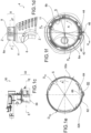
- a trigger dispensing device comprising a trigger dispensing head 2 and a bottle 4, to which the head 2 may be firmly applied, is collectively indicated at 1.
- the bottle 4 consists of a bottle body 6, closed at the bottom, and a neck 8 having a free edge 9 which delimits a circular bottle mouth 10, having a central axis Z.
- the neck 8 consists of a thin annular wall, with an outer neck surface 8a, having an outer neck diameter D8e, and an inner neck surface 8b, coaxial to the outer neck surface 8a, having an inner neck diameter D8i.
- said thin annular wall extends from said free edge 9, arranged on the top, to an annular flange 11, arranged on the bottom, protruding outwards radially.
- the bottle 4 is equipped with a suction tube 12 made in a single piece with the bottle body 6, for example, arranged externally thereto, at the front.
- the suction tube 12 is open at the bottom of the body of the bottle 6 in order to suck up the product to be dispensed and is open at the top by means of an engagement opening 14, on the part of the neck 8, inside the bottle 4.
- the engagement opening is arranged in the bottle body 6, i.e. below the neck 8, for example, offset with respect to the central axis Z.
- the head 4 comprises a main tube 20, for example equipped with an end section 22 made of a material that is more flexible than the remaining part of the main tube 20, intended to engage with the suction tube 12 for sealed insertion into the engagement opening 14.
- the head 2 After the head 2 has been separated from the bottle 4, for example to fill said bottle, the head must be reapplied to the neck so that the main tube 20 enters into the engagement opening 14.
- the engagement opening 14 is offset from the central axis Z, it is essential for the head 2 to be able to be applied to the neck 8 of the bottle 4 when said head and said neck are in a relative predefined unequivocal angular position, to which corresponds the insertion of the main tube 20 in the engagement opening 14.
- the head 2 comprises a frame 30, typically made as a single piece, which supports the functional components of said head, such as a trigger, a piston, valve means, a nozzle and the like; preferably, moreover, said frame comprises portions that define additional functional parts of the head, such as a dispensing duct, a pressure chamber for the piston, and the like.
- the frame 30 comprises a skirt 32 consisting of a thin annular wall that, when the head is applied to the neck, is coaxial with the main axis Z.
- a connection system comprises the neck 8 of the bottle 4 and the skirt 32 of the frame 30, suitable to engage mutually, with axial overlap, by snap-engagement and according to a bayonet connection.
- the neck 8 of the bottle 4 comprises a rib 40, generally made in one piece with the neck 8, protruding from the outer surface 8a of the neck 8 for a maximum height Hmax with respect to the outer surface 8a of the neck 8.
- Said maximum height Hmax is such as to create a structural interference with the skirt 32 and in particular with the inner surface 32b of said skirt, so as to prevent the insertion of the skirt 32 on the neck 8 if not in a predefined angular position between the skirt 32 and the neck 8, which will be discussed hereinafter.
- said maximum height Hmax of the rib 8 is such that said rib 8 protrudes from the outer surface 8a of the neck 8 by an amount greater than half of the difference between the inner diameter D32i of the skirt 32 and the outer diameter D8e of the neck 8, so as to have a condition of interference with the inner surface 32b of the skirt 32 even if the skirt 32 is fitted on the neck 8 in a manner offset from the main axis Z of said neck 8.
- the maximum height Hmax of the rib 8 is such that: Hmax > 1 2 D 8 e ⁇ D 32 i
- the rib 40 preferably extends axially from the free edge 9 to the annular flange 11 of the neck 8. According to further embodiments, the rib 40 extends axially only for a section between the free edge 9 and the annular flange 11.
- the rib 40 has an upper face 40' that does not guide the insertion of the skirt of the frame; for example, preferably, the upper face 40' lies on an imaginary plane perpendicular to the main axis Z.
- the rib 40 has a first side 42 and a second side 44, joined together by a limit surface 46 which preferably corresponds to the maximum height Hmax of the rib 40.
- the first side 42 is inclined with respect to a circumferential direction, and in particular forms a ramp outwards according to the counterclockwise direction of rotation A.
- the second side 44 is flat and has a radial arrangement.
- the limit surface 46 is flat.
- an imaginary plane orthogonal to the main axis Z defines an imaginary line 8* which on the outer surface 8a of the neck 8 separates an upper band 8', which extends from the free edge 9 to said imaginary line 8*, and a lower band 8", which extends from said imaginary line 8* to the annular flange 11.
- the outer surface 8a of the neck 8 Adjacent to the rib 40, in the direction of travel A corresponding to the counterclockwise direction of rotation A, the outer surface 8a of the neck 8 has a first coupling region 120, comprising a circumferential section of said outer surface 8a.
- the first coupling region 120 comprises a first coupling shoulder 121 having axial extension and comprising a first section 121' in the upper band 8' and a second section 121" in the lower band 8".
- the first coupling region 120 has a first coupling guide 122, adjacent, in particular joined, to the first coupling shoulder 121; said first coupling guide 122 consists of two sloping walls 122', 122", of increasing thickness from the free edge 9 towards the annular flange 11, circumferentially separated by a first coupling entry passage 122′′′ shaped like a funnel.
- first coupling guide 122 preferably entirely contained in the upper band 8', a surface without projections is found that defines a first circumferential coupling pocket 124, into which flows the first coupling entry passage 122′′′.
- the first coupling region 120 provides for a first coupling slide 126, having extension in the upper band 8', adjacent, in particular joined, to the first coupling guide 122.
- the first coupling slide 126 has a decreasing thickness from the free edge 9 towards the annular flange 11, and consists of a slide part 126'.
- first coupling corridor 130 that extends circumferentially, in continuity with the first coupling pocket 124.
- the first coupling region 120 provides for a first coupling stop 128, with a section 128' extending in the upper band 8', adjacent, in particular joined, to the first coupling slide 126, and a section 128′′′ in the lower band 8", for example recessed with respect to the section 128'.
- the first coupling region 120 comprises a first coupling shelf 129, near the free edge 9, having mainly circumferential extension, adjacent, in particular joined, to the first coupling stop 128.
- the outer surface 8a of the neck 8 Adjacent to the first coupling region 120, in said direction of travel A, the outer surface 8a of the neck 8 has a second coupling region 140 with structural and functional characteristics similar to those of the first coupling region 120.
- said second coupling region 140 comprises:
- the outer surface 8a of the neck 8 has a reference region 160, for example adjacent to the second coupling region 140.
- said reference region 160 is arranged said rib 40.
- said reference region 160 comprises a reference shoulder 50, spaced circumferentially from the rib 40 or, in one embodiment, joined thereto, on the side opposite to the counterclockwise direction of rotation A ( Figure 5 ).
- the reference region 160 comprises a reference guide 162, having extension in the upper band 8', adjacent, in particular joined, to the second coupling shelf 149; the reference guide 162 has an increasing thickness from the free edge 9 towards the annular flange 11 and consists of a guide part 162'.
- the reference region 160 provides for a reference pocket 164 without projections, extending to the rib 40, in the upper band 8' band and in the lower band 8".
- the skirt 32 comprises a seat 60 that opens like an inlet on the inner surface 32b; the seat 60, which develops axially from the free edge 38, is configured to accommodate at least partially the rib 40 and to allow the insertion of the frame 30 on the neck 8.
- the seat 60 is arranged circumferentially in a predefined angular position, so that the insertion of the frame 30 on the neck only takes place when the frame and the neck are in the correct relative angular position.
- the seat 60 has a first side 62 and a second side 64, joined by a limit surface 66.
- the first side 62 is inclined with respect to the tangential direction, so as to create a ramp outwards in the counterclockwise direction of rotation A; preferably, moreover, the second side 64 is inclined with respect to the tangential direction, so as to create a ramp inwards in the counterclockwise direction of rotation A.
- the skirt 32 comprises a coupling window 202, 212 through the thickness of the annular wall, suitable to accommodate the respective coupling guide 122, 142 of the coupling region 120, 140.
- the skirt 32 comprises a flexible coupling tab 204, 214, suitable to deform by sliding over the respective coupling guide 122, 142 and snapping into the respective coupling pocket 124, 144, thus snapping the frame 30 to the neck 8 when arranged in the relative assembled position.
- said coupling tab 204, 214 is arranged at the lower edge of the respective coupling window 202, 212.
- the skirt 32 comprises a coupling tooth 206, 216 suitable to penetrate the respective coupling passage 122′′′, 142′′′ to guide the application of the frame 30 to the neck 8.
- said coupling tooth 206, 216 is protruding from the inner surface 32b of the skirt 32, arranged axially below the respective coupling tab 204, 214.
- skirt 32 has a reference window 220, suitable to accommodate the reference slide 162 of the reference region 160 of the neck 8.
- a flexible reference tab 222 suitable to deform by sliding over the reference guide 162 and to snap into the reference pocket 164, thus snapping the frame 30 to the neck 8, when placed in the relative assembled position.
- two reference teeth 224, 226, protruding from the inner surface 32b of the skirt 32 and arranged below the reference tab 222, spaced circumferentially so as to be adjacent to the reference guide 162 to guide the insertion of the skirt 32 on the neck 8.
- the rib 40 is aligned with the seat 60, so as to be inserted therein; correspondingly, the coupling tabs 204, 214 are aligned with the coupling guides 122, 142 and the reference tab 222 is aligned with the reference guide 162.
- the rib 40 is accommodated in the seat 60, the coupling tabs 204, 214 are accommodated in the coupling pockets 124, 144 and the reference tab 222 is accommodated in the reference pocket 164.
- the coupling tab 204, 214 is aligned with the respective coupling slide 126, as well as the respective coupling teeth 206, 216, thus allowing the skirt 32 to be removed from the neck 8 smoothly.
- the rib creates an obstacle to the insertion of the skirt on the neck of the bottle, even if the skirt and the neck are offset in an attempt to apply them forcibly, due to the dimensional configuration of the rib.
- the seat is obtained on the outer surface of the neck of the bottle and the rib on the inner surface of the skirt of the frame.
- the neck has only one coupling region and, correspondingly, the skirt has only one coupling window with relative coupling tab and coupling tooth.
- the neck has three or more coupling regions and, correspondingly, the skirt has three or more coupling windows with relative coupling tab and coupling tooth.
- connection system according to the present invention meets the needs of the sector and overcomes the drawbacks mentioned in reference to the prior art, since the rib constitutes an insurmountable obstacle for the insertion of the skirt of the frame on the neck of the bottle, except by a considerable deformation of the skirt itself, unusual in normal operation.
- the rib constitutes an insurmountable obstacle for the insertion of the skirt of the frame on the neck of the bottle, unless it is aligned with the seat of the skirt, as occurs only in the correct relative assembled position.
Landscapes
- Closures For Containers (AREA)
Claims (17)
- Abgabevorrichtung (1), umfassend eine Flasche (4), einen Trigger-Abgabekopf (2) und ein Verbindungssystem zwischen dem Trigger-Abgabekopf (2) und der Flasche (4), wobei das Verbindungssystem umfasst:- eine Schürze bzw. Einfassung (32) des Rahmens (30), die aus einer zylindrischen Ringwand mit einem freien Rand (38) und einer Innenfläche bzw. -oberfläche (32b) mit einem Innendurchmesser (D32i) besteht, wobei die Einfassung mit einem Sitz (60) versehen ist, der als ein Einlass an der Innenfläche (32) konfiguriert ist, und zwar zugänglich durch den freien Rand (38);- einen Hals (8) der Flasche (4), die aus einer zylindrischen Ringwand mit einem freien Rand (9) und einer Außenfläche bzw. -oberfläche (8a) mit einem Außendurchmesser (D8e) besteht, wobei der Hals mit einer Rippe (40) versehen ist, die von der Außenfläche (8a) vorsteht;wobei die Rippe (40) in einer relativen montierten Position winkelmäßig mit dem Sitz (60) ausgerichtet ist und die Rippe (40) außerhalb dieser relativen montierten Position ein Hindernis für das axiale Einsetzen der Einfassung (32) an dem Hals (8) darstellt;wobei die Abgabevorrichtung dadurch gekennzeichnet ist, dass die Rippe (40) bei definierter Drehrichtung (A) eine erste Seite (42) aufweist, die in Bezug auf eine Tangentialrichtung geneigt ist, um gemäß dieser Drehrichtung (A) eine Rampe nach außen zu bilden.
- Abgabevorrichtung nach Anspruch 1, wobei die Rippe (40) in der relativen montierten Position axial in den Sitz (60) einsetzbar ist.
- Abgabevorrichtung nach Anspruch 1 oder 2, wobei die Rippe (40) eine maximale Höhe (Hmax) relativ zu der Außenfläche (8a) des Halses (8) aufweist, die größer ist als die Hälfte der Differenz zwischen dem Innendurchmesser (D32i) der Einfassung (32) und dem Außendurchmesser (D8e) des Halses (8):

- Abgabevorrichtung nach einem der vorhergehenden Ansprüche, wobei die Rippe (40) eine zweite Seite (44) aufweist, und zwar flach und radial.
- Abgabevorrichtung nach Anspruch 4, wobei die Rippe (40) eine Grenzfläche bzw. -oberfläche (46) aufweist, die die erste Seite (42) und die zweite Seite (44) verbindet.
- Abgabevorrichtung nach Anspruch 4 oder Anspruch 5, wobei der Sitz (60) eine erste Seite (62) aufweist, die in Bezug auf die Tangentialrichtung geneigt ist, um eine Rampe nach außen in der Drehrichtung (A) zu bilden.
- Abgabevorrichtung nach einem der vorhergehenden Ansprüche, und zwar vom Bajonetttyp.
- Abgabevorrichtung nach einem der vorhergehenden Ansprüche, wobei die Einfassung (32) auf den Hals (8) aufgeschnappt ist.
- Abgabevorrichtung nach Anspruch 8, wobei die Außenfläche (8a) des Halses (8) zumindest einen Kopplungsbereich (120,140) aufweist, der eine Kopplungsschulter (121,141), eine Kopplungsführung (122,142) winkelig ausgerichtet mit einer Kopplungstasche (124,144), einen Kupplungsschieber (126,146) winkelig ausgerichtet mit einem Kopplungskorridor (130,150) ausgerichtet, einen Kupplungsstopp (128,148) umfasst.
- Abgabevorrichtung nach Anspruch 9, wobei die Einfassung (32) für jeden Kopplungsbereich (120,140) des Halses (8) ein Kopplungsfenster (202,212) und einen flexiblen Kopplungsfortsatz (204,214) zum Einschnappen der Einfassung (32) in den bzw. an dem Hals (8) umfasst.
- Abgabevorrichtung nach Anspruch 9 oder Anspruch 10, wobei die Außenfläche (8a) des Halses (8) einen Referenzbereich (160) aufweist, der eine Referenzschulter (50) umfasst.
- Abgabevorrichtung nach einem der Ansprüche 9 bis 11, wobei die Außenfläche (8a) des Halses (8) einen Referenzbereich (160) aufweist, der eine Referenzführung (162) und eine Referenztasche (164) umfasst, die winkelig mit der Referenzführung (162) ausgerichtet ist.
- Abgabevorrichtung nach Anspruch 12, wobei die Einfassung (32) ein Referenzfenster (220) und einen flexiblen Referenzfortsatz (222) für den Schnappeingriff der Einfassung (32) mit dem Hals (8) aufweist.
- Abgabevorrichtung nach einem der vorhergehenden Ansprüche, wobei:- die Flasche (4) aus einem unten geschlossenen Flaschenkörper (6) und dem Hals (8) besteht, wobei der freie Rand (9) eine kreisförmige Flaschenmündung (10) mit einer Mittelachse (Z) begrenzt, und- wobei die Flasche (4) mit einem Saugrohr (12) ausgestattet ist, das einstückig mit dem Flaschenkörper (6) ausgebildet ist, unten am Flaschenkörper (6) offen ist und oben durch eine Eingriffsöffnung (14) offen ist, die im Inneren der Flasche (4) angeordnet ist, und- wobei die Eingriffsöffnung von der Mittelachse (Z) versetzt ist.
- Abgabevorrichtung nach Anspruch 14, wobei die Eingriffsöffnung in dem Flaschenkörper (6), d.h. unterhalb des Halses (8), platziert ist.
- Abgabevorrichtung nach Anspruch 14 oder Anspruch 15, wobei der Abgabekopf (4) ein Hauptrohr (20) umfasst, das dazu bestimmt ist, mit dem Saugrohr (12) zum abgedichteten Einsetzen in die Eingriffsöffnung (14) in Eingriff zu kommen.
- Abgabevorrichtung nach Anspruch 16, wobei das Hauptrohr (20) mit einem Endabschnitt (22) versehen ist, der aus einem flexibleren Material als der restliche Teil des Hauptrohrs (20) besteht.
Applications Claiming Priority (1)
| Application Number | Priority Date | Filing Date | Title |
|---|---|---|---|
| PCT/IT2020/000002 WO2021140530A1 (en) | 2020-01-09 | 2020-01-09 | Snap-on dispensing head |
Publications (2)
| Publication Number | Publication Date |
|---|---|
| EP4087687A1 EP4087687A1 (de) | 2022-11-16 |
| EP4087687B1 true EP4087687B1 (de) | 2024-07-31 |
Family
ID=70050167
Family Applications (1)
| Application Number | Title | Priority Date | Filing Date |
|---|---|---|---|
| EP20715205.9A Active EP4087687B1 (de) | 2020-01-09 | 2020-01-09 | Snap-on ausgabekopf |
Country Status (4)
| Country | Link |
|---|---|
| US (1) | US11806735B2 (de) |
| EP (1) | EP4087687B1 (de) |
| ES (1) | ES2989652T3 (de) |
| WO (1) | WO2021140530A1 (de) |
Citations (2)
| Publication number | Priority date | Publication date | Assignee | Title |
|---|---|---|---|---|
| US6138873A (en) * | 1997-03-28 | 2000-10-31 | Guala Dispensing S.P.A. | Bayonet coupling between a spray pump and a bottle of a substance to be sprayed |
| WO2014189994A2 (en) * | 2013-05-21 | 2014-11-27 | S.C. Johnson & Son, Inc. | Trigger sprayer with bottle filling conduit |
Family Cites Families (5)
| Publication number | Priority date | Publication date | Assignee | Title |
|---|---|---|---|---|
| US5725132A (en) * | 1996-09-25 | 1998-03-10 | Contico International, Inc. | Dispenser with snap-fit container connection |
| US7478739B2 (en) * | 2006-03-14 | 2009-01-20 | Meadwestvaco Calmar, Inc. | Snap down bayonet connector |
| ITBS20070060A1 (it) * | 2007-04-18 | 2008-10-19 | Guala Dispensing Spa | Sistema di chiusura per un contenitore, ad esempio per erogatore a grilletto |
| ITBS20130159A1 (it) * | 2013-11-05 | 2015-05-06 | Guala Dispensing Spa | Dispositivo di erogazione a grilletto |
| US11014107B2 (en) * | 2017-11-07 | 2021-05-25 | Guala Dispensing S.P.A. | Connection system |
-
2020
- 2020-01-09 WO PCT/IT2020/000002 patent/WO2021140530A1/en not_active Ceased
- 2020-01-09 EP EP20715205.9A patent/EP4087687B1/de active Active
- 2020-01-09 US US17/756,281 patent/US11806735B2/en active Active
- 2020-01-09 ES ES20715205T patent/ES2989652T3/es active Active
Patent Citations (2)
| Publication number | Priority date | Publication date | Assignee | Title |
|---|---|---|---|---|
| US6138873A (en) * | 1997-03-28 | 2000-10-31 | Guala Dispensing S.P.A. | Bayonet coupling between a spray pump and a bottle of a substance to be sprayed |
| WO2014189994A2 (en) * | 2013-05-21 | 2014-11-27 | S.C. Johnson & Son, Inc. | Trigger sprayer with bottle filling conduit |
Also Published As
| Publication number | Publication date |
|---|---|
| EP4087687A1 (de) | 2022-11-16 |
| ES2989652T3 (es) | 2024-11-27 |
| US20220410194A1 (en) | 2022-12-29 |
| WO2021140530A1 (en) | 2021-07-15 |
| US11806735B2 (en) | 2023-11-07 |
Similar Documents
| Publication | Publication Date | Title |
|---|---|---|
| EP3706917B1 (de) | Verbindungssystem | |
| AU2008229561B2 (en) | Dispensing assembly having removably attachable accessories | |
| EP2143662B1 (de) | Kolben mit einer Lichtendichtung und Kartuschensysteme, die solche Kolben verwenden | |
| US6971552B2 (en) | Aerosol dispenser | |
| US6932244B2 (en) | Aerosol dispensing device | |
| US7497354B2 (en) | Fluid dispenser | |
| US11471903B2 (en) | Device for packaging a fluid product and dispensing the product in doses, including a reusable bottle | |
| EP1754542B1 (de) | Airless-Abgabepumpe mit Originalitätssicherung | |
| US5353836A (en) | Dispensing valve | |
| EP2870076B1 (de) | Verschlussanordnung und behälter mit einer verschlussanordnung | |
| MX2013008953A (es) | Mecanismo de union para un envase. | |
| PL204847B1 (pl) | Zamknięcie przeznaczone dla pojemnika | |
| NZ204280A (en) | Dispensing valve and spout for bag-in-box container | |
| CN103596698B (zh) | 固定环以及使用这种环的流体制品分配器 | |
| EP4087687B1 (de) | Snap-on ausgabekopf | |
| EP3145856B2 (de) | Flüssigkeitsspender mit ventil | |
| EP0417891A1 (de) | Flaschenverschluss | |
| US10384222B2 (en) | Pump actuator head | |
| WO2009074972A1 (en) | Orientation system for a closure | |
| US11247222B2 (en) | Connection system between a bottle and a dispensing head | |
| CA3097603A1 (en) | Bottle cap assembly | |
| US20240278270A1 (en) | Trigger-type dispensing head for a dispensing device for pasty products such as toothpastes | |
| US11679402B2 (en) | Dispenser for compounds in paste form | |
| WO2022084459A1 (en) | Aerosol dispensing device and method for manufacturing an aerosol dispensing device |
Legal Events
| Date | Code | Title | Description |
|---|---|---|---|
| STAA | Information on the status of an ep patent application or granted ep patent |
Free format text: STATUS: UNKNOWN |
|
| STAA | Information on the status of an ep patent application or granted ep patent |
Free format text: STATUS: THE INTERNATIONAL PUBLICATION HAS BEEN MADE |
|
| PUAI | Public reference made under article 153(3) epc to a published international application that has entered the european phase |
Free format text: ORIGINAL CODE: 0009012 |
|
| STAA | Information on the status of an ep patent application or granted ep patent |
Free format text: STATUS: REQUEST FOR EXAMINATION WAS MADE |
|
| 17P | Request for examination filed |
Effective date: 20220519 |
|
| AK | Designated contracting states |
Kind code of ref document: A1 Designated state(s): AL AT BE BG CH CY CZ DE DK EE ES FI FR GB GR HR HU IE IS IT LI LT LU LV MC MK MT NL NO PL PT RO RS SE SI SK SM TR |
|
| DAV | Request for validation of the european patent (deleted) | ||
| DAX | Request for extension of the european patent (deleted) | ||
| P01 | Opt-out of the competence of the unified patent court (upc) registered |
Effective date: 20230523 |
|
| STAA | Information on the status of an ep patent application or granted ep patent |
Free format text: STATUS: EXAMINATION IS IN PROGRESS |
|
| 17Q | First examination report despatched |
Effective date: 20230712 |
|
| GRAP | Despatch of communication of intention to grant a patent |
Free format text: ORIGINAL CODE: EPIDOSNIGR1 |
|
| STAA | Information on the status of an ep patent application or granted ep patent |
Free format text: STATUS: GRANT OF PATENT IS INTENDED |
|
| INTG | Intention to grant announced |
Effective date: 20240506 |
|
| GRAS | Grant fee paid |
Free format text: ORIGINAL CODE: EPIDOSNIGR3 |
|
| GRAA | (expected) grant |
Free format text: ORIGINAL CODE: 0009210 |
|
| STAA | Information on the status of an ep patent application or granted ep patent |
Free format text: STATUS: THE PATENT HAS BEEN GRANTED |
|
| AK | Designated contracting states |
Kind code of ref document: B1 Designated state(s): AL AT BE BG CH CY CZ DE DK EE ES FI FR GB GR HR HU IE IS IT LI LT LU LV MC MK MT NL NO PL PT RO RS SE SI SK SM TR |
|
| REG | Reference to a national code |
Ref country code: CH Ref legal event code: EP Ref country code: GB Ref legal event code: FG4D |
|
| REG | Reference to a national code |
Ref country code: DE Ref legal event code: R096 Ref document number: 602020034839 Country of ref document: DE |
|
| REG | Reference to a national code |
Ref country code: IE Ref legal event code: FG4D |
|
| REG | Reference to a national code |
Ref country code: LT Ref legal event code: MG9D |
|
| REG | Reference to a national code |
Ref country code: ES Ref legal event code: FG2A Ref document number: 2989652 Country of ref document: ES Kind code of ref document: T3 Effective date: 20241127 |
|
| REG | Reference to a national code |
Ref country code: NL Ref legal event code: MP Effective date: 20240731 |
|
| PG25 | Lapsed in a contracting state [announced via postgrant information from national office to epo] |
Ref country code: PT Free format text: LAPSE BECAUSE OF FAILURE TO SUBMIT A TRANSLATION OF THE DESCRIPTION OR TO PAY THE FEE WITHIN THE PRESCRIBED TIME-LIMIT Effective date: 20241202 |
|
| REG | Reference to a national code |
Ref country code: AT Ref legal event code: MK05 Ref document number: 1707983 Country of ref document: AT Kind code of ref document: T Effective date: 20240731 |
|
| PG25 | Lapsed in a contracting state [announced via postgrant information from national office to epo] |
Ref country code: PT Free format text: LAPSE BECAUSE OF FAILURE TO SUBMIT A TRANSLATION OF THE DESCRIPTION OR TO PAY THE FEE WITHIN THE PRESCRIBED TIME-LIMIT Effective date: 20241202 |
|
| PG25 | Lapsed in a contracting state [announced via postgrant information from national office to epo] |
Ref country code: NO Free format text: LAPSE BECAUSE OF FAILURE TO SUBMIT A TRANSLATION OF THE DESCRIPTION OR TO PAY THE FEE WITHIN THE PRESCRIBED TIME-LIMIT Effective date: 20241031 |
|
| PG25 | Lapsed in a contracting state [announced via postgrant information from national office to epo] |
Ref country code: GR Free format text: LAPSE BECAUSE OF FAILURE TO SUBMIT A TRANSLATION OF THE DESCRIPTION OR TO PAY THE FEE WITHIN THE PRESCRIBED TIME-LIMIT Effective date: 20241101 Ref country code: NL Free format text: LAPSE BECAUSE OF FAILURE TO SUBMIT A TRANSLATION OF THE DESCRIPTION OR TO PAY THE FEE WITHIN THE PRESCRIBED TIME-LIMIT Effective date: 20240731 Ref country code: PL Free format text: LAPSE BECAUSE OF FAILURE TO SUBMIT A TRANSLATION OF THE DESCRIPTION OR TO PAY THE FEE WITHIN THE PRESCRIBED TIME-LIMIT Effective date: 20240731 Ref country code: FI Free format text: LAPSE BECAUSE OF FAILURE TO SUBMIT A TRANSLATION OF THE DESCRIPTION OR TO PAY THE FEE WITHIN THE PRESCRIBED TIME-LIMIT Effective date: 20240731 |
|
| PG25 | Lapsed in a contracting state [announced via postgrant information from national office to epo] |
Ref country code: BG Free format text: LAPSE BECAUSE OF FAILURE TO SUBMIT A TRANSLATION OF THE DESCRIPTION OR TO PAY THE FEE WITHIN THE PRESCRIBED TIME-LIMIT Effective date: 20240731 |
|
| PG25 | Lapsed in a contracting state [announced via postgrant information from national office to epo] |
Ref country code: LV Free format text: LAPSE BECAUSE OF FAILURE TO SUBMIT A TRANSLATION OF THE DESCRIPTION OR TO PAY THE FEE WITHIN THE PRESCRIBED TIME-LIMIT Effective date: 20240731 |
|
| PG25 | Lapsed in a contracting state [announced via postgrant information from national office to epo] |
Ref country code: IS Free format text: LAPSE BECAUSE OF FAILURE TO SUBMIT A TRANSLATION OF THE DESCRIPTION OR TO PAY THE FEE WITHIN THE PRESCRIBED TIME-LIMIT Effective date: 20241130 Ref country code: AT Free format text: LAPSE BECAUSE OF FAILURE TO SUBMIT A TRANSLATION OF THE DESCRIPTION OR TO PAY THE FEE WITHIN THE PRESCRIBED TIME-LIMIT Effective date: 20240731 |
|
| PG25 | Lapsed in a contracting state [announced via postgrant information from national office to epo] |
Ref country code: HR Free format text: LAPSE BECAUSE OF FAILURE TO SUBMIT A TRANSLATION OF THE DESCRIPTION OR TO PAY THE FEE WITHIN THE PRESCRIBED TIME-LIMIT Effective date: 20240731 |
|
| PG25 | Lapsed in a contracting state [announced via postgrant information from national office to epo] |
Ref country code: RS Free format text: LAPSE BECAUSE OF FAILURE TO SUBMIT A TRANSLATION OF THE DESCRIPTION OR TO PAY THE FEE WITHIN THE PRESCRIBED TIME-LIMIT Effective date: 20241031 |
|
| PG25 | Lapsed in a contracting state [announced via postgrant information from national office to epo] |
Ref country code: RS Free format text: LAPSE BECAUSE OF FAILURE TO SUBMIT A TRANSLATION OF THE DESCRIPTION OR TO PAY THE FEE WITHIN THE PRESCRIBED TIME-LIMIT Effective date: 20241031 Ref country code: PL Free format text: LAPSE BECAUSE OF FAILURE TO SUBMIT A TRANSLATION OF THE DESCRIPTION OR TO PAY THE FEE WITHIN THE PRESCRIBED TIME-LIMIT Effective date: 20240731 Ref country code: NO Free format text: LAPSE BECAUSE OF FAILURE TO SUBMIT A TRANSLATION OF THE DESCRIPTION OR TO PAY THE FEE WITHIN THE PRESCRIBED TIME-LIMIT Effective date: 20241031 Ref country code: NL Free format text: LAPSE BECAUSE OF FAILURE TO SUBMIT A TRANSLATION OF THE DESCRIPTION OR TO PAY THE FEE WITHIN THE PRESCRIBED TIME-LIMIT Effective date: 20240731 Ref country code: LV Free format text: LAPSE BECAUSE OF FAILURE TO SUBMIT A TRANSLATION OF THE DESCRIPTION OR TO PAY THE FEE WITHIN THE PRESCRIBED TIME-LIMIT Effective date: 20240731 Ref country code: IS Free format text: LAPSE BECAUSE OF FAILURE TO SUBMIT A TRANSLATION OF THE DESCRIPTION OR TO PAY THE FEE WITHIN THE PRESCRIBED TIME-LIMIT Effective date: 20241130 Ref country code: HR Free format text: LAPSE BECAUSE OF FAILURE TO SUBMIT A TRANSLATION OF THE DESCRIPTION OR TO PAY THE FEE WITHIN THE PRESCRIBED TIME-LIMIT Effective date: 20240731 Ref country code: GR Free format text: LAPSE BECAUSE OF FAILURE TO SUBMIT A TRANSLATION OF THE DESCRIPTION OR TO PAY THE FEE WITHIN THE PRESCRIBED TIME-LIMIT Effective date: 20241101 Ref country code: FI Free format text: LAPSE BECAUSE OF FAILURE TO SUBMIT A TRANSLATION OF THE DESCRIPTION OR TO PAY THE FEE WITHIN THE PRESCRIBED TIME-LIMIT Effective date: 20240731 Ref country code: BG Free format text: LAPSE BECAUSE OF FAILURE TO SUBMIT A TRANSLATION OF THE DESCRIPTION OR TO PAY THE FEE WITHIN THE PRESCRIBED TIME-LIMIT Effective date: 20240731 Ref country code: AT Free format text: LAPSE BECAUSE OF FAILURE TO SUBMIT A TRANSLATION OF THE DESCRIPTION OR TO PAY THE FEE WITHIN THE PRESCRIBED TIME-LIMIT Effective date: 20240731 |
|
| PG25 | Lapsed in a contracting state [announced via postgrant information from national office to epo] |
Ref country code: SM Free format text: LAPSE BECAUSE OF FAILURE TO SUBMIT A TRANSLATION OF THE DESCRIPTION OR TO PAY THE FEE WITHIN THE PRESCRIBED TIME-LIMIT Effective date: 20240731 Ref country code: RO Free format text: LAPSE BECAUSE OF FAILURE TO SUBMIT A TRANSLATION OF THE DESCRIPTION OR TO PAY THE FEE WITHIN THE PRESCRIBED TIME-LIMIT Effective date: 20240731 Ref country code: DK Free format text: LAPSE BECAUSE OF FAILURE TO SUBMIT A TRANSLATION OF THE DESCRIPTION OR TO PAY THE FEE WITHIN THE PRESCRIBED TIME-LIMIT Effective date: 20240731 |
|
| PG25 | Lapsed in a contracting state [announced via postgrant information from national office to epo] |
Ref country code: EE Free format text: LAPSE BECAUSE OF FAILURE TO SUBMIT A TRANSLATION OF THE DESCRIPTION OR TO PAY THE FEE WITHIN THE PRESCRIBED TIME-LIMIT Effective date: 20240731 |
|
| PG25 | Lapsed in a contracting state [announced via postgrant information from national office to epo] |
Ref country code: CZ Free format text: LAPSE BECAUSE OF FAILURE TO SUBMIT A TRANSLATION OF THE DESCRIPTION OR TO PAY THE FEE WITHIN THE PRESCRIBED TIME-LIMIT Effective date: 20240731 |
|
| PG25 | Lapsed in a contracting state [announced via postgrant information from national office to epo] |
Ref country code: SK Free format text: LAPSE BECAUSE OF FAILURE TO SUBMIT A TRANSLATION OF THE DESCRIPTION OR TO PAY THE FEE WITHIN THE PRESCRIBED TIME-LIMIT Effective date: 20240731 |
|
| REG | Reference to a national code |
Ref country code: DE Ref legal event code: R097 Ref document number: 602020034839 Country of ref document: DE |
|
| PLBE | No opposition filed within time limit |
Free format text: ORIGINAL CODE: 0009261 |
|
| STAA | Information on the status of an ep patent application or granted ep patent |
Free format text: STATUS: NO OPPOSITION FILED WITHIN TIME LIMIT |
|
| 26N | No opposition filed |
Effective date: 20250501 |
|
| REG | Reference to a national code |
Ref country code: CH Ref legal event code: PL |
|
| PG25 | Lapsed in a contracting state [announced via postgrant information from national office to epo] |
Ref country code: SE Free format text: LAPSE BECAUSE OF FAILURE TO SUBMIT A TRANSLATION OF THE DESCRIPTION OR TO PAY THE FEE WITHIN THE PRESCRIBED TIME-LIMIT Effective date: 20240731 |
|
| PG25 | Lapsed in a contracting state [announced via postgrant information from national office to epo] |
Ref country code: LU Free format text: LAPSE BECAUSE OF NON-PAYMENT OF DUE FEES Effective date: 20250109 Ref country code: MC Free format text: LAPSE BECAUSE OF FAILURE TO SUBMIT A TRANSLATION OF THE DESCRIPTION OR TO PAY THE FEE WITHIN THE PRESCRIBED TIME-LIMIT Effective date: 20240731 |
|
| PG25 | Lapsed in a contracting state [announced via postgrant information from national office to epo] |
Ref country code: BE Free format text: LAPSE BECAUSE OF NON-PAYMENT OF DUE FEES Effective date: 20250131 |
|
| PG25 | Lapsed in a contracting state [announced via postgrant information from national office to epo] |
Ref country code: CH Free format text: LAPSE BECAUSE OF NON-PAYMENT OF DUE FEES Effective date: 20250131 |
|
| REG | Reference to a national code |
Ref country code: BE Ref legal event code: MM Effective date: 20250131 |
|
| PGFP | Annual fee paid to national office [announced via postgrant information from national office to epo] |
Ref country code: FR Payment date: 20251231 Year of fee payment: 7 |
|
| PG25 | Lapsed in a contracting state [announced via postgrant information from national office to epo] |
Ref country code: IE Free format text: LAPSE BECAUSE OF NON-PAYMENT OF DUE FEES Effective date: 20250109 |
|
| PGFP | Annual fee paid to national office [announced via postgrant information from national office to epo] |
Ref country code: GB Payment date: 20260123 Year of fee payment: 7 |
|
| PGFP | Annual fee paid to national office [announced via postgrant information from national office to epo] |
Ref country code: ES Payment date: 20260202 Year of fee payment: 7 |
|
| PGFP | Annual fee paid to national office [announced via postgrant information from national office to epo] |
Ref country code: DE Payment date: 20260123 Year of fee payment: 7 |
|
| PGFP | Annual fee paid to national office [announced via postgrant information from national office to epo] |
Ref country code: IT Payment date: 20251218 Year of fee payment: 7 |